JP2010048244A - Power transmission device of natural energy collection system - Google Patents
Power transmission device of natural energy collection system Download PDFInfo
- Publication number
- JP2010048244A JP2010048244A JP2008215975A JP2008215975A JP2010048244A JP 2010048244 A JP2010048244 A JP 2010048244A JP 2008215975 A JP2008215975 A JP 2008215975A JP 2008215975 A JP2008215975 A JP 2008215975A JP 2010048244 A JP2010048244 A JP 2010048244A
- Authority
- JP
- Japan
- Prior art keywords
- power transmission
- transmission device
- natural energy
- brake mechanism
- electric motor
- Prior art date
- Legal status (The legal status is an assumption and is not a legal conclusion. Google has not performed a legal analysis and makes no representation as to the accuracy of the status listed.)
- Granted
Links
- 230000005540 biological transmission Effects 0.000 title claims abstract description 38
- 230000007246 mechanism Effects 0.000 claims abstract description 83
- 239000012530 fluid Substances 0.000 claims abstract description 76
- 230000009467 reduction Effects 0.000 claims abstract description 74
- 239000007788 liquid Substances 0.000 claims abstract description 17
- 239000010687 lubricating oil Substances 0.000 claims description 25
- 239000003638 chemical reducing agent Substances 0.000 claims description 24
- 238000005192 partition Methods 0.000 claims description 22
- 238000011084 recovery Methods 0.000 claims description 22
- 230000008878 coupling Effects 0.000 claims description 16
- 238000010168 coupling process Methods 0.000 claims description 16
- 238000005859 coupling reaction Methods 0.000 claims description 16
- 238000010248 power generation Methods 0.000 description 34
- 230000006378 damage Effects 0.000 description 6
- 230000000694 effects Effects 0.000 description 5
- XEEYBQQBJWHFJM-UHFFFAOYSA-N Iron Chemical compound [Fe] XEEYBQQBJWHFJM-UHFFFAOYSA-N 0.000 description 4
- 230000009471 action Effects 0.000 description 4
- 238000001514 detection method Methods 0.000 description 4
- 239000004519 grease Substances 0.000 description 4
- 238000000034 method Methods 0.000 description 4
- 238000007789 sealing Methods 0.000 description 4
- 230000006835 compression Effects 0.000 description 3
- 238000007906 compression Methods 0.000 description 3
- 230000033001 locomotion Effects 0.000 description 3
- XAGFODPZIPBFFR-UHFFFAOYSA-N aluminium Chemical compound [Al] XAGFODPZIPBFFR-UHFFFAOYSA-N 0.000 description 2
- 229910052782 aluminium Inorganic materials 0.000 description 2
- 230000008901 benefit Effects 0.000 description 2
- 230000008859 change Effects 0.000 description 2
- 238000009792 diffusion process Methods 0.000 description 2
- 229910052742 iron Inorganic materials 0.000 description 2
- 239000000463 material Substances 0.000 description 2
- 239000007787 solid Substances 0.000 description 2
- 238000003756 stirring Methods 0.000 description 2
- 230000002159 abnormal effect Effects 0.000 description 1
- 239000000470 constituent Substances 0.000 description 1
- 238000001816 cooling Methods 0.000 description 1
- 238000009826 distribution Methods 0.000 description 1
- 230000005484 gravity Effects 0.000 description 1
- 239000000314 lubricant Substances 0.000 description 1
- 238000005461 lubrication Methods 0.000 description 1
- 239000003921 oil Substances 0.000 description 1
- 230000002093 peripheral effect Effects 0.000 description 1
- 238000003825 pressing Methods 0.000 description 1
- 230000004044 response Effects 0.000 description 1
- 238000009987 spinning Methods 0.000 description 1
- 230000002195 synergetic effect Effects 0.000 description 1
Images


Classifications
-
- F—MECHANICAL ENGINEERING; LIGHTING; HEATING; WEAPONS; BLASTING
- F16—ENGINEERING ELEMENTS AND UNITS; GENERAL MEASURES FOR PRODUCING AND MAINTAINING EFFECTIVE FUNCTIONING OF MACHINES OR INSTALLATIONS; THERMAL INSULATION IN GENERAL
- F16H—GEARING
- F16H1/00—Toothed gearings for conveying rotary motion
- F16H1/28—Toothed gearings for conveying rotary motion with gears having orbital motion
- F16H1/32—Toothed gearings for conveying rotary motion with gears having orbital motion in which the central axis of the gearing lies inside the periphery of an orbital gear
-
- F—MECHANICAL ENGINEERING; LIGHTING; HEATING; WEAPONS; BLASTING
- F03—MACHINES OR ENGINES FOR LIQUIDS; WIND, SPRING, OR WEIGHT MOTORS; PRODUCING MECHANICAL POWER OR A REACTIVE PROPULSIVE THRUST, NOT OTHERWISE PROVIDED FOR
- F03D—WIND MOTORS
- F03D15/00—Transmission of mechanical power
- F03D15/10—Transmission of mechanical power using gearing not limited to rotary motion, e.g. with oscillating or reciprocating members
-
- F—MECHANICAL ENGINEERING; LIGHTING; HEATING; WEAPONS; BLASTING
- F03—MACHINES OR ENGINES FOR LIQUIDS; WIND, SPRING, OR WEIGHT MOTORS; PRODUCING MECHANICAL POWER OR A REACTIVE PROPULSIVE THRUST, NOT OTHERWISE PROVIDED FOR
- F03D—WIND MOTORS
- F03D7/00—Controlling wind motors
- F03D7/02—Controlling wind motors the wind motors having rotation axis substantially parallel to the air flow entering the rotor
- F03D7/0204—Controlling wind motors the wind motors having rotation axis substantially parallel to the air flow entering the rotor for orientation in relation to wind direction
-
- F—MECHANICAL ENGINEERING; LIGHTING; HEATING; WEAPONS; BLASTING
- F03—MACHINES OR ENGINES FOR LIQUIDS; WIND, SPRING, OR WEIGHT MOTORS; PRODUCING MECHANICAL POWER OR A REACTIVE PROPULSIVE THRUST, NOT OTHERWISE PROVIDED FOR
- F03D—WIND MOTORS
- F03D7/00—Controlling wind motors
- F03D7/02—Controlling wind motors the wind motors having rotation axis substantially parallel to the air flow entering the rotor
- F03D7/022—Adjusting aerodynamic properties of the blades
- F03D7/0224—Adjusting blade pitch
-
- F—MECHANICAL ENGINEERING; LIGHTING; HEATING; WEAPONS; BLASTING
- F03—MACHINES OR ENGINES FOR LIQUIDS; WIND, SPRING, OR WEIGHT MOTORS; PRODUCING MECHANICAL POWER OR A REACTIVE PROPULSIVE THRUST, NOT OTHERWISE PROVIDED FOR
- F03D—WIND MOTORS
- F03D80/00—Details, components or accessories not provided for in groups F03D1/00 - F03D17/00
- F03D80/70—Bearing or lubricating arrangements
-
- F—MECHANICAL ENGINEERING; LIGHTING; HEATING; WEAPONS; BLASTING
- F05—INDEXING SCHEMES RELATING TO ENGINES OR PUMPS IN VARIOUS SUBCLASSES OF CLASSES F01-F04
- F05B—INDEXING SCHEME RELATING TO WIND, SPRING, WEIGHT, INERTIA OR LIKE MOTORS, TO MACHINES OR ENGINES FOR LIQUIDS COVERED BY SUBCLASSES F03B, F03D AND F03G
- F05B2260/00—Function
- F05B2260/70—Adjusting of angle of incidence or attack of rotating blades
- F05B2260/79—Bearing, support or actuation arrangements therefor
-
- F—MECHANICAL ENGINEERING; LIGHTING; HEATING; WEAPONS; BLASTING
- F05—INDEXING SCHEMES RELATING TO ENGINES OR PUMPS IN VARIOUS SUBCLASSES OF CLASSES F01-F04
- F05B—INDEXING SCHEME RELATING TO WIND, SPRING, WEIGHT, INERTIA OR LIKE MOTORS, TO MACHINES OR ENGINES FOR LIQUIDS COVERED BY SUBCLASSES F03B, F03D AND F03G
- F05B2260/00—Function
- F05B2260/90—Braking
- F05B2260/902—Braking using frictional mechanical forces
-
- F—MECHANICAL ENGINEERING; LIGHTING; HEATING; WEAPONS; BLASTING
- F05—INDEXING SCHEMES RELATING TO ENGINES OR PUMPS IN VARIOUS SUBCLASSES OF CLASSES F01-F04
- F05B—INDEXING SCHEME RELATING TO WIND, SPRING, WEIGHT, INERTIA OR LIKE MOTORS, TO MACHINES OR ENGINES FOR LIQUIDS COVERED BY SUBCLASSES F03B, F03D AND F03G
- F05B2260/00—Function
- F05B2260/90—Braking
- F05B2260/904—Braking using hydrodynamic forces
-
- Y—GENERAL TAGGING OF NEW TECHNOLOGICAL DEVELOPMENTS; GENERAL TAGGING OF CROSS-SECTIONAL TECHNOLOGIES SPANNING OVER SEVERAL SECTIONS OF THE IPC; TECHNICAL SUBJECTS COVERED BY FORMER USPC CROSS-REFERENCE ART COLLECTIONS [XRACs] AND DIGESTS
- Y02—TECHNOLOGIES OR APPLICATIONS FOR MITIGATION OR ADAPTATION AGAINST CLIMATE CHANGE
- Y02E—REDUCTION OF GREENHOUSE GAS [GHG] EMISSIONS, RELATED TO ENERGY GENERATION, TRANSMISSION OR DISTRIBUTION
- Y02E10/00—Energy generation through renewable energy sources
- Y02E10/70—Wind energy
- Y02E10/72—Wind turbines with rotation axis in wind direction
Abstract
Description
本発明は、自然エネルギ回収システムの動力伝達装置、特にその電動モータの過回転を防止する機能を備えた自然エネルギ回収システムの動力伝達装置に関する。 The present invention relates to a power transmission device for a natural energy recovery system, and more particularly to a power transmission device for a natural energy recovery system having a function of preventing over-rotation of the electric motor.
特許文献1における風力発電装置においては、風力発電ユニットを電動モータによって旋回駆動し(ヨー駆動し)、風車ブレードを常時風の方向に向けて風力を効率よく翼に作用させるように構成したヨー制御(方位制御)手段を備えた風力発電装置が開示されている。この特許文献1では、台風等の強風を風速センサが検知すると、モータに設けられた摩擦ブレーキを作動させ、前記風力発電ユニットの旋回を固定・制動してモータの過回転を防止する技術が開示されている。 In the wind power generator in Patent Document 1, the wind power generator unit is driven to rotate (yaw drive) by an electric motor, and the wind turbine blades are always directed in the direction of the wind so that the wind force efficiently acts on the blades. A wind turbine generator having a (direction control) means is disclosed. In this patent document 1, when a wind speed sensor detects a strong wind such as a typhoon, a technique is disclosed in which a friction brake provided in the motor is operated to fix and brake the turning of the wind power generation unit to prevent over-rotation of the motor. Has been.
しかしながら、自然相手の風力発電システムでは、極めて強い突風などの過大な負荷が風力発電ユニットに作用すると、該風力発電ユニットが摩擦ブレーキによる制動を振り切って旋回してしまうことある。この場合、摩擦ブレーキは、摩擦板同士が摩擦接触した状態のまま回転させられることになるため、摩擦熱が発生して該制動手段が損傷する恐れがある。 However, in a wind power generation system of a natural counterpart, when an excessive load such as a very strong gust wind acts on the wind power generation unit, the wind power generation unit may turn by swinging the braking by the friction brake. In this case, the friction brake is rotated while the friction plates are in frictional contact with each other, so that frictional heat is generated and the braking means may be damaged.
特許文献2では、こうした不具合に対し、摩擦ブレーキに温度検出センサを取り付けて該摩擦ブレーキの温度を常時検出し、摩擦ブレーキが許容温度以上にまで上昇すると、制御部が該摩擦ブレーキの電動モータに対する制動を終了させるように構成した技術を開示している。 In Patent Document 2, a temperature detection sensor is attached to the friction brake to constantly detect the temperature of the friction brake, and when the friction brake rises to an allowable temperature or higher, the control unit controls the friction brake with respect to the electric motor of the friction brake. A technique configured to end braking is disclosed.
特許文献2に開示されているような構成で、強力な負荷側からの強制駆動が発生したときに摩擦ブレーキによる制動を中止するようにすると、確かに、摩擦ブレーキの損傷は回避できるようにはなる。しかしながら、これでは摩擦ブレーキでの制動中止に伴って風力発電ユニットは当該突風の過大な負荷をそのまま受けて旋回してしまうことになる。そのため、電動モータが極めて高い回転速度で強制回転させられて損傷してしまうという問題が新たに発生する恐れがある。 With the configuration disclosed in Patent Document 2, if the braking by the friction brake is stopped when the forced driving from the strong load side is generated, the damage to the friction brake can surely be avoided. Become. However, in this case, the wind power generation unit turns as it receives the excessive load of the gust as the brake is stopped by the friction brake. Therefore, there is a possibility that a problem that the electric motor is forcibly rotated at an extremely high rotational speed and damaged may be newly generated.
即ち、電動モータを用いて、例えばヨー駆動装置を構築しようとした場合、2000kWの発電機の場合、ヨー駆動減速機自体において1000〜2000程度の高い「減速比」にて設計されている(ヨー旋回輪とピニオンによる減速比を掛け合わせると更に高い減速比となる)。このため、台風、竜巻、突風等の予期せぬ巨大な負荷をエネルギ回収メンバ側から受けると、減速機の出力軸側が強制回転させられ、同じ値の高い「増速比」にてモータが強制回転させられることになる。この結果、電動モータは定格回転速度(一般には4極モータで1500rpm(50Hz)または1800rpm(60Hz))の数倍から10数倍の回転速度で回転させられる状態となり、損傷は免れにくい。この事情は太陽光発電での受光パネルを駆動するシステム等でも同じである。 That is, when an attempt is made to construct a yaw drive device using an electric motor, for example, in the case of a 2000 kW generator, the yaw drive reducer itself is designed with a high “reduction ratio” of about 1000 to 2000 (yaw drive). Multiplying the reduction ratio of the swivel wheel and pinion gives a higher reduction ratio). For this reason, when an unexpectedly large load such as a typhoon, a tornado or a gust is received from the energy recovery member side, the output shaft side of the reduction gear is forcibly rotated, and the motor is forced at the same "speed increase ratio". It will be rotated. As a result, the electric motor can be rotated at a rotational speed that is several times to 10 times the rated rotational speed (generally 1500 rpm (50 Hz) or 1800 rpm (60 Hz) for a four-pole motor), and damage is difficult to avoid. This situation is the same in a system for driving a light receiving panel in solar power generation.
また、特許文献2において開示されている技術では、前記摩擦ブレーキが作動するように設計されているのは、旋回停止後、即ち、一度停止した状態のときのみであり、例えば電動モータによって旋回中に、同じ旋回方向に強い突風による旋回力が加わったときには、摩擦ブレーキはそもそも作動するように設計されていないため、電動モータはそのまま超高速回転状態に入ってしまい、全く対応できないという問題もあった。 Further, in the technique disclosed in Patent Document 2, the friction brake is designed to operate only after the turning is stopped, that is, when it is once stopped, for example, while turning by an electric motor. In addition, when a turning force due to a strong gust of wind is applied in the same turning direction, the friction brake is not designed to operate in the first place. It was.
更に、上記特許文献1、2においてなされている摩擦ブレーキ制御は、センサ等の検知に基づいて「制御部」が電気的、或いは油圧的制御指令を発して摩擦ブレーキを作動させるものであったため、信頼性が低いという問題を有していた。それは、もともとこのような大きな変動荷重が発生するのは、通常と大きく異なる天候あるいは気象状況であることを考慮すると、暴風雨や落雷等によってセンサが故障したり、制御部の制御基板が浸水したり、配線等が物理的に断線したりした場合に、制動実行の制御指令自体が出せなくなってしまうことが考えられるためである。 Furthermore, the friction brake control performed in Patent Documents 1 and 2 above is that the "control unit" generates an electrical or hydraulic control command based on detection by a sensor or the like to operate the friction brake. It had the problem of low reliability. In consideration of the fact that such a large fluctuating load is generated by the weather or weather conditions that are significantly different from normal ones, the sensor may break down due to storms, lightning strikes, etc., or the control board of the control unit may be submerged. This is because when the wiring or the like is physically disconnected, it is considered that the control command itself for executing the braking cannot be issued.
本発明は、このような従来未解決の問題を解決するためになされたものであって、回転系に摩擦負荷を付与するという従来の制動体系を抜本的に見直し、電動モータが過回転状態となることを、より簡易且つ確実な構成で回避することのできる自然エネルギ回収システムの動力伝達装置を提供することその課題としている。 The present invention has been made in order to solve such a conventional unsolved problem, and has fundamentally reviewed the conventional braking system of applying a friction load to the rotating system, and the electric motor is in an over-rotation state. It is an object of the present invention to provide a power transmission device of a natural energy recovery system that can avoid this with a simpler and more reliable configuration.
本発明は、風力、太陽光等の自然エネルギを回収するシステムに使用される自然エネルギ回収システムの動力伝達装置であって、電動モータと、該電動モータと連結され、被駆動機械を駆動する出力軸を備えた減速機と、前記電動モータと減速機の出力軸との間の動力伝達経路に対して付設され、前記出力軸の回転速度が上昇したときに、該動力伝達経路の回転抵抗を増大させる液体を媒体とした流体ブレーキ機構と、を備えたことにより上記課題を解決したものである。 The present invention relates to a power transmission device for a natural energy recovery system used in a system for recovering natural energy such as wind power and sunlight, and is an electric motor and an output connected to the electric motor to drive a driven machine. A reduction gear provided with a shaft and a power transmission path between the electric motor and the output shaft of the reduction gear. When the rotational speed of the output shaft increases, the rotational resistance of the power transmission path is reduced. The above-described problem is solved by including a fluid brake mechanism using a liquid to be increased as a medium.
本発明においては、減速機の出力軸の回転速度が上昇したときに、「液体を媒体とした流体ブレーキ機構」によって該動力伝達経路の回転抵抗を「敢えて」増大させるようにしている。 In the present invention, when the rotational speed of the output shaft of the speed reducer increases, the rotational resistance of the power transmission path is “intentionally” increased by the “fluid brake mechanism using liquid as a medium”.
この点で、効率を考慮した一般的な動力伝達装置の設計とは逆行する設計となる。本発明において、「液体を媒体とした流体ブレーキ機構」とは、いわゆるブレーキシュー(摩擦板)を用いた固体同士の摺動摩擦を利用した制動付与機構ではなく、「液体が流体として機能するときに本来的に有する性質を利用した制動機構」のことを指している。具体的には、例えば、液体が外から力を受けたときの圧縮抵抗、形状を変えられるときの変形抵抗、自身の中を物体が動くときの撹拌抵抗、粘性抵抗、或いは剪断抵抗、狭い流路を移動するときの通過抵抗等の性質を利用した制動のことである。 In this respect, the design is opposite to the design of a general power transmission device in consideration of efficiency. In the present invention, the “fluid brake mechanism using a liquid as a medium” is not a brake applying mechanism using sliding friction between solids using a so-called brake shoe (friction plate), but “when the liquid functions as a fluid” It refers to a “braking mechanism that uses the inherent properties”. Specifically, for example, the compression resistance when the liquid receives a force from the outside, the deformation resistance when the shape is changed, the stirring resistance when the object moves in itself, the viscous resistance, or the shear resistance, the narrow flow This refers to braking using properties such as passage resistance when moving on a road.
流体ブレーキ機構は、例えば後述するヴィスカスカップリングのように、動力伝達経路の構成メンバに対して直接組み込んで機能させるものでもよく、また、動力伝達経路の構成メンバには直接的には組み込まれていないが、例えば減速機内の潤滑油の通過抵抗をうまく利用することにより、より速い回転運動をしようとする部材の動きに抵抗を与えるような構成とされていてもよい。なお、2以上の流体ブレーキ機構を併用しても良い。 The fluid brake mechanism may be directly incorporated into and functioned with a component member of the power transmission path, for example, as will be described later, such as a Viscous coupling, and is directly incorporated into a component member of the power transmission path. However, it may be configured to give resistance to the movement of a member that tries to perform faster rotational motion by, for example, making good use of the passage resistance of the lubricating oil in the speed reducer. Two or more fluid brake mechanisms may be used in combination.
流体ブレーキ機構は、電気的な制御指令を受けて機能するものではなく、出力軸の回転速度が上昇すると、流体の性質を使用して「自動的に」機能する機械的な構造なので、電源や制御系を必要とせず、また、摺動面での摩擦を利用するものでもないので、暴風雨や落雷発生等の気象状況の厳しいときでも安定した作動が期待できる。更には、基本的に簡素な構成を維持できるため、装置全体が複雑化することもなく、十分な制動機能を確保しながら小型化、軽量化、低コスト化にも寄与する。 The fluid brake mechanism does not function in response to an electrical control command, and it is a mechanical structure that functions “automatically” using the properties of the fluid when the rotational speed of the output shaft increases. Since a control system is not required and friction on the sliding surface is not used, stable operation can be expected even in severe weather conditions such as storms and lightning strikes. Furthermore, since a simple configuration can be basically maintained, the entire device is not complicated, and contributes to reduction in size, weight, and cost while ensuring a sufficient braking function.
摩擦付与手段に頼ることなく、電動モータが過回転状態となることを、簡易且つ確実な構成で回避することができる。 It is possible to avoid the electric motor from being over-rotated with a simple and reliable configuration without relying on the friction applying means.
以下、本発明の実施形態の一例に係る自然エネルギ回収システムの動力伝達装置を風力発電システムの駆動装置に適用した場合の例について説明する。 Hereinafter, an example in which a power transmission device of a natural energy recovery system according to an example of an embodiment of the present invention is applied to a driving device of a wind power generation system will be described.
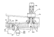
図17は、風力発電システム10の概略正面図、図18は、同側面図である。
FIG. 17 is a schematic front view of the wind
この風力発電システム(自然エネルギ回収システム)10は、円筒支柱11の最上部に発電ユニット12を備える。図19は、発電ユニット12の概略を示す斜視図である。発電ユニット12には、ヨー(Yaw)駆動用の駆動装置(動力伝達装置)14とピッチ(Pitch)駆動用の駆動装置16が組み込まれている。ヨー駆動用の駆動装置14は、発電ユニット12全体の旋回角を制御するためのもので、図示の例では4個描写されている。ピッチ駆動用の駆動装置16は、ノーズコーン18に取り付けられる3枚の風車ブレード20のピッチ角を制御するためのものである。
This wind power generation system (natural energy recovery system) 10 includes a
本実施形態では、ヨー駆動用の駆動装置14に本発明が適用されているため、ここではヨー駆動用の駆動装置14について詳細に説明する。
In the present embodiment, since the present invention is applied to the
図20は、ヨー駆動用の駆動装置14付近の構成を示す一部破断の正面図である。
FIG. 20 is a partially broken front view showing a configuration in the vicinity of the
ヨー駆動用の駆動装置14は、電動モータMoと減速機Goを備える。減速機Goの構成及び作用は後に詳述する。
The
ヨー駆動用の駆動装置14の出力軸64Aにはヨー駆動用ピニオン24が取り付けられている。ヨー駆動用ピニオン24は、ヨーベアリング26の内輪を構成するリングギヤ部28に内接噛合している。このリングギヤ部28は、円筒支柱11側に固定されており、ヨーベアリング26の外輪を構成する外枠部32は発電ユニット12のケーシング本体34側に固定されている。この構成により、電動モータMoによってヨー駆動用の駆動装置14の出力軸64Aを回転させることにより、ヨー駆動用ピニオン24及びヨーベアリング26のリングギヤ部28の噛合を介して発電ニット12全体を円筒支柱11の軸心36(図19)周りで旋回させることができる。この結果、ノーズコーン18を所望の方向(例えば風上の方向)に向けることができ、効率的に風圧を受けることができる。
A
なお、風速が大きいときには、風車ブレード20の受ける風圧が最も小さくなるように、ヨー駆動用の駆動装置14及びピッチ駆動用の駆動装置16によってそれぞれ発電ユニット12の旋回角及び風車ブレード20のピッチ角が制御されると共に、発電ユニット12の旋回がブレーキユニット39によって止められるようになっている。ブレーキユニット39は、ブレーキスラスタ39A、ヨーブレーキキャリパ39B、ブレーキディスク39C等から構成される。このブレーキユニット39は、いわゆる通常運転時での発電ユニット12の旋回を抑制するもので後述する本発明に係る流体ブレーキ機構とは異なる。
When the wind speed is high, the turning angle of the
ここで、風車ブレード20側から受ける極めて大きな風圧によって駆動装置14の出力軸を介してモータMoが過回転してしまうのを、駆動装置14の流体ブレーキ機構の機能によって阻止する構成について、詳細に説明する。
Here, the configuration for preventing the motor Mo from over-rotating via the output shaft of the
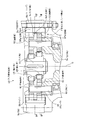
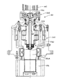
このヨー駆動用の駆動装置14は、図2に示されるように、電動モータMoと、内接噛合遊星歯車機構の入力側減速段40及び出力側減速段42を直列に連結した減速機Goを備える。これは、この減速機Goが、機能上、1/1000〜1/2000という極めて高い減速比を必要とするためである。先ず、入力側減速段40について説明する。
As shown in FIG. 2, the
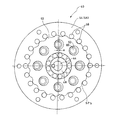
図1に、入力側減速段40の詳細を示す。図1は、便宜上左右対称には描写されていない。図1の左側は、後述する外ピン58が存在する位置の断面、図1の右側は外ピン58が存在しない位置の断面をそれぞれ描写している。図3、図4は、それぞれ図1の矢視III−III線及びIV−IV線に沿う断面図である。
FIG. 1 shows details of the input-
入力側減速段40は、モータ軸と一体(兼用)の入力軸44、該入力軸44に設けられた2つの偏心体46、48、該偏心体46、48を介して偏心量eの偏心揺動をする2枚(複数)の外歯歯車50、52、該外歯歯車50、52が内接噛合する内歯歯車54を備えている。外歯歯車50、52は、その偏心位相が丁度180度ずれている。即ち、2つの外歯歯車50、52は、互いに離反する方向に偏心した状態を維持しながら揺動回転する。内歯歯車54は入力側減速段40の部分のケーシング56を兼ねている。内歯歯車54の内歯は、それぞれ円筒状の外ピン58によって構成されている。内歯歯車54の内歯の数(外ピン58の数)は、この例では「22」であり、外歯歯車50、52の外歯の数「21」より1だけ多い。外歯歯車50、52には、内ピン60が内ローラ62を介して遊嵌されている。内ピン60は(入力側減速段40の)出力軸64と一体化されている。該内ピン60を介して固定状態にある内歯歯車54に対する外歯歯車50、52の相対回転(自転)が取り出され、更に該内ピン60と一体化されている(入力側減速段40の)出力軸64から出力側減速段42へと出力されるようになっている。
The input-
出力側減速段42の構成は、減速比が入力側減速段の減速比より大きく設定されているほかは、機構学的には入力側減速段40と同様の構成・作用の動力伝達経路を有する。この例では出力側減速段42には本発明は適用されていないため、入力側減速段40の構成メンバと機能的に類似する部材に対して末尾にAを付加した符号を付すにとどめ、重複説明を省略する。なお、出力側減速段42は、入力側減速段40よりも減速比が大きいことから、入力側減速段40側よりも外歯歯車の外径に対する偏心量の比率が小さくなっている。
The output side reduction stage 42 has a power transmission path that is mechanically similar to the input
本発明に係る電動モータMoの過回転を防止するための流体ブレーキ機構FBoは、入力側減速段40、出力側減速段42のうち、入力側減速段40の方に付設されている。これは、入力側減速段40の側(通常時により高速回転する側)に付設する方が、1)出力軸64A側から見たときに「より大きく増速回転」する回転メンバに対して流体ブレーキ機構FBoを組み込むことになるため、流体ブレーキ機構FBoで発生し得るトルクをより有効に効かせることができること、及び、2)減速比の大小の関係で、外歯歯車の外径に対する偏心量の比率の大きな入力側減速段40の方が後述する流体ポンプとしての機能を実現し易い、という理由による。
The fluid brake mechanism FBo for preventing over-rotation of the electric motor Mo according to the present invention is attached to the input
以下、流体ブレーキ機構FBoについて詳細に説明する。 Hereinafter, the fluid brake mechanism FBo will be described in detail.
図1、図4及び図5を主に参照して、この実施形態における流体ブレーキ機構FBoは、外歯歯車50、52と、2枚の遮蔽板70、72と、仕切り板74と、を備える。
Referring mainly to FIGS. 1, 4, and 5, the fluid brake mechanism FBo in this embodiment includes
外歯歯車50、52は、出力軸64A側が強制駆動回転されると、その回転が伝達されてくる部材である。また、潤滑油(液体)の中に配設され、2枚の遮蔽板70、72及び仕切り板74の機能により、これから詳細に説明するように、その回転速度が上昇するに連れて潤滑油から受ける回転抵抗が飛躍的に増大する部材である。そのため、流体ブレーキ機構FBoにおいて「出力軸側からの強制駆動回転が伝達され、液体中に配設され、回転速度の上昇に応じて液体から受ける回転抵抗が増大する回転部」として機能し得る。
The external gears 50 and 52 are members to which the rotation is transmitted when the
遮蔽板70、72は、それぞれ2枚の外歯歯車50、52の軸方向外側に配置され、該複数の外歯歯車50、52と前記内歯歯車54との間の空間SPa、SPbを閉塞可能である。
The shielding plates 70 and 72 are disposed on the axially outer sides of the two
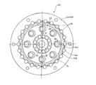
仕切り板74の単体形状を図5に示す。仕切り板74は、外ピン58の半径方向内側に沿った形状の凹部74Aと、内歯歯車54の外ピン58の存在しない本体部分54A(図1参照)の内周に沿った形状の外周部74Bと、を備える。仕切り板74は、このような形状を有しているため、それぞれの外歯歯車50、52の外周の空間SPa、SPb内に存在する潤滑油が軸方向に相互に行き来するのを制限可能である。仕切り板74には、潤滑油が軸方向に相互に行き来するのを制限する程度を規定するための貫通孔74Pが形成されている。貫通孔74Pの内径D1は、これを大きく取ると、潤滑油の相互の行き来がよりし易くなってポンプ作用(流体ブレーキ機構FBoの制動機能)が弱められ、小さく取ると、ポンプ作用は高められる。なお、仕切り板74は、外歯歯車50、52及び内歯歯車54等の鉄系の素材の熱膨張率より大きな熱膨張率を有する素材、例えばアルミニウム等で形成されている。
A single shape of the
次に、この駆動装置14の作用を、特に流体ブレーキ機構FBoの制動機能に着目して説明する。
Next, the operation of the
電動モータMoのモータ軸と一体(兼用)の入力軸44が回転すると、2つの偏心体46、48を介して2枚の外歯歯車50、52が180度の位相差で偏心揺動する。しかしながら、それぞれの外歯歯車50、52は、内ピン60によってその自転が拘束されているため、各外歯歯車50、52は、ほとんど揺動のみを行う。この実施形態では内歯歯車54がケーシング56と一体化されているため、外歯歯車50、52は、1回揺動するごとに内歯歯車54との噛合位置が1歯だけずれ、該内歯歯車54に対して歯数差に相当する角度だけ相対回転する(入力軸44の回転と逆方向に自転する)。この相対回転成分が内ピン60を介して(入力側減速段40の)出力軸64から出力側減速段42に出力される。
When the
ここで、減速機Goの内部には、潤滑油が充填されている。この実施形態では、外歯歯車50、52の軸方向両側に遮蔽板70、72が配置されており、且つ、それぞれの外歯歯車50、52の軸方向中央には仕切り板74が配置されている。そのため、外歯歯車50の半径方向外側に位置する潤滑油は、遮蔽板70、外歯歯車50、仕切り板74、及び内歯歯車54によって閉塞された空間SPaから脱出することができず、仕切り板74の貫通孔74Pを介して隣の空間SPbとの行き来ができるだけとなる。全く同様に、外歯歯車52の半径方向外側に位置する潤滑油は、遮蔽板72、外歯歯車52、仕切り板74、及び内歯歯車54によって閉塞された空間SPbから脱出することができず、仕切り板74の貫通孔74Pを介して隣の空間SPaとの行き来ができるだけとなる。
Here, the reduction gear Go is filled with lubricating oil. In this embodiment, shielding plates 70 and 72 are arranged on both sides of the
一方、外歯歯車50、52は、その偏心位相が180度ずれている。そのため、空間SPaと空間SPbは、互いに逆方向にそれぞれの容積が常時変化する。即ち、空間SPaの容積がより大きくなるときは空間SPbの容積がより小さくなるように、空間SPaの容積がより小さくなるときは空間SPbの容積がより大きくなるように変化する。この結果、空間SPa及び空間SPbでは、潤滑油の圧縮・膨張が繰り返されると共に、各貫通孔74Pでは一方の空間SPa(またはSPb)から他方の空間SPb(またはSPa)へと潤滑油が移動する現象が起こる。
On the other hand, the eccentric gears 50 and 52 are 180 degrees out of phase. Therefore, the volume of the space SPa and the space SPb always changes in opposite directions. That is, when the volume of the space SPa becomes larger, the volume of the space SPb becomes smaller, and when the volume of the space SPa becomes smaller, the volume of the space SPb becomes larger. As a result, the compression and expansion of the lubricating oil is repeated in the space SPa and the space SPb, and the lubricating oil moves from one space SPa (or SPb) to the other space SPb (or SPa) in each through
通常運転のときは、この移動による抵抗はわずかである(僅かなように貫通孔74Pの内径D1が設定されている)。しかしながら、極めて大きな風圧によって(出力側減速段42の)出力軸64Aが強制的に回転させられると、その回転は、極めて大きな「増速比」にて増速され、外歯歯車50、52を通常運転時より非常に速く回転・揺動させる。周知のように、圧力損失は流速の2乗に比例するため、予想を超える速度で外歯歯車50、52が揺動しようとすると、貫通孔74Pを行き来しようとする潤滑油が加速度的に大きな抵抗となり、外歯歯車50、52の揺動速度の上昇を抑える。すなわち、出力軸64Aの回転速度の上昇に伴って、該回転速度の上昇よりも遥かに大きな比率で回転抵抗が増大し、この結果、入力軸(モータ軸)44の過回転が防止される。
During normal operation, the resistance due to this movement is small (the inner diameter D1 of the through
この実施形態においては、仕切り板74がアルミニウムで形成されている。このため、地域、季節等によって発電ユニット12が高温下で使用されるときには、仕切り板74自体が鉄系の外歯歯車50、52や内歯歯車54と比較してより膨張する。このため、空間SPaと空間SPbの容積がより減少すると共に、空間SPaと空間SPbの密閉度もより高まることになる。したがって、高温下で潤滑油の粘度が下がって圧力損失が低下気味になるのを、良好に相殺することができる。発電ユニット12が低温下で使用されるときには、これと全く逆の相殺が行われる。
In this embodiment, the
貫通孔74Pの内径D1の適正値は、空間SPaと空間SPbの密閉度及び外歯歯車50、52の偏心量e、潤滑油の粘度等に依存する。空間SPaと空間SPbの密閉度が高く、外歯歯車50、52の偏心量eが大きく、潤滑油の粘度が高いようなときやグリースにより潤滑するようなときには、貫通孔74Pでの通過抵抗が大きくなり易いため、内径D1を大きめにとって通常運転時での圧力損失を小さく抑えるようにする。
The appropriate value of the inner diameter D1 of the through
また、寒い地域で使用するとき(潤滑油の粘度が高いとき)や、年間を通じて台風等が殆ど発生しない地域で使用するとき(過回転となる恐れが少ないとき)、或いは、外歯歯車50、52の偏心量eが大きく、空間SPaと空間SPbの容積変化が大きいときなどでは、通常時の圧力損失を極力抑えるべく、例えば、図6及び図7に示されるように、仕切り板74−2の凹部74A(図5)を、一個置きに連結した大きな貫通空間74Dとし、潤滑油がこの大きな貫通空間74Dを行き来できるようにしてもよい。これは、貫通孔74Pを1個置きに大きな内径とした構成と実質的に同等である。
Also, when used in cold areas (when the viscosity of the lubricating oil is high), when used in areas where typhoons or the like hardly occur throughout the year (when there is little risk of over-rotation), or the
逆に、暑い地域で使用するときや、台風や竜巻等の発生しやすい地域で使用するとき、或いは偏心量eが小さく空間SPaと空間SPbの容積変化が小さいときなどでは、貫通孔74Pの内径D1は、小さく設定すると良い。
On the other hand, when used in a hot area, in an area where typhoons or tornadoes are likely to occur, or when the eccentricity e is small and the volume change between the space SPa and the space SPb is small, the inner diameter of the through
仕切り板74の貫通孔74Pは、複数あるため、その一部のみを、使用する地域あるいは季節等に応じて、一時的、または恒久的に閉塞することによって、現場での貫通孔74Pの通過抵抗の調整に活用しても良い。なお、仕切り板74に貫通孔がなくても、遮蔽板での密閉度を最適化することにより、ポンプ作用の活用によって相応の制動効果を得ることも可能である。
Since there are a plurality of through
例えば、前述した特許文献1、2のように、強風による発電ユニット12の強制旋回を回転部材に摩擦負荷を与えるタイプの制動(いわゆる摩擦ブレーキ)によって押さえ込もうとした場合、不可避的に大量の摩擦熱が発生し、当該摩擦ブレーキ自体の損傷に直結する。しかし、摩擦ブレーキを守るために制動自体を中止したのでは、今度は電動モータが損傷してしまう。摩擦負荷を与えるタイプの制動手段を用いてこれらの不具合を両方とも回避するには、巨大な容量の摩擦ブレーキを用意して(制動を中止することなく)制動を掛け続ける必要があり、大幅な重量増大及びコスト増大を招く。しかも、特許文献2での技術のように、停止時に制動を掛ける設計では旋回中での電動モータの保護はできないため、仮に旋回中でも制動を行うように設計変更するとすれば、更に大きな制動容量が必要となる。なによりも根本的な問題は、もともとこのような大きな強制駆動負荷が発生するのは、暴風雨や落雷発生下等の通常とは大きく異なる気象状況下であることが多いということである。このような非日常的な劣悪環境下で行われる緊急避難的制動を、「センサ検知に基づいて制御部から制御指令が出されることによって作動する摩擦ブレーキ」による制動に頼るのは危険である。それは、(1)当該センサ自体が故障したり、制御部の制御基板が浸水したりや配線等が物理的に断線したりすると、制動実行のための制御指令自体が出せなくなってしまうためであり、加えて、(2)仮に巨大な容量の摩擦ブレーキを組み込み、且つ制御指令が正常に発生されたとしても、摩擦ブレーキの摺動面(摩擦付与面)の状態が暴風雨に晒されて正常でなくなっていると、同じ押圧力を与えても同じ摩擦力(制動力)が得られない、ことが考えられるためである。
For example, as described in Patent Documents 1 and 2 described above, when the forced turning of the
本実施形態に係る流体ブレーキ機構FBoは、センサ系の検知に基づいて電気的制御により作動するものでもなく、また特定の摺動面に対して摩擦を付与するタイプのものではないため、劣悪な環境下でも、停止時、旋回時の区別なく、しかも過回転が厳しくなればなる程より強い制動力が確実に発生する。そのため、制動手段及び電動モータの双方を損傷からより安全に守ることができる。 The fluid brake mechanism FBo according to the present embodiment is not operated by electrical control based on detection of a sensor system, and is not a type that imparts friction to a specific sliding surface, so that it is inferior. Even in an environment, a stronger braking force is surely generated as the over-rotation becomes severe without distinction between stopping and turning. Therefore, both the braking means and the electric motor can be protected more safely from damage.
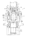
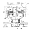
次に、図8及び図9を用いて本発明の他の実施形態の一例について説明する。 Next, an example of another embodiment of the present invention will be described with reference to FIGS.
この実施形態に係る減速機G1は、流体ブレーキ機構の構成以外は先の実施形態に係る減速機Goと基本構造は同一であるため、便宜上同一または機能的に同一の部位に下2桁が同一の符号を付すこととする。電動モータM1は、先の実施形態の電動モータMoと同一のもので良い。図8に示されるように、この実施形態では、減速機G1の入力側減速段140の入力軸144と該入力側減速段140の出力軸164との間に、いわゆるヴィスカスカップリング構造の流体ブレーキ機構FB1が介在されている。この流体ブレーキ機構FB1は、入力側減速段140の入力軸144に植設された複数の入力側プレート(出力軸側からの強制駆動回転が伝達される回転部としての第1プレート)167と、入力側減速段140の出力軸164に植設され、入力側プレート167より遅く回転する複数の出力側プレート(第2プレート)168とが、軸方向に交互に配置されている。各プレート167、168の間には粘性流体(液体)が封入されている。なお、この例では、先の実施形態での流体ブレーキ機構FBoが併用されているが、流体ブレーキ機構FB1単体で用いても良い。
The speed reducer G1 according to this embodiment is the same in basic structure as the speed reducer Go according to the previous embodiment except for the configuration of the fluid brake mechanism. The reference numeral is attached. The electric motor M1 may be the same as the electric motor Mo of the previous embodiment. As shown in FIG. 8, in this embodiment, a fluid having a so-called Viscous coupling structure is provided between the
入力側プレート167の回転速度は入力軸(モータ軸)144の回転速度と同一である。また、出力側プレート168は、入力側減速段140の減速比は1/21であるため、入力軸144の1/21の回転速度で該入力軸144と反対の方向に回転する。今、電動モータM1の定格回転速度を2000rpmとすると、(入力側プレート167と出力側プレート168は回転方向が逆であるため)両プレート167、168の定格運転時の相対回転速度は、2000+2000/21=2095rpmとなる。この相対回転速度が発生している状況では、両プレート167、168による粘性流体の剪断抵抗が無視できる程度に小さくなるように、流体ブレーキ機構FB1の各種諸元が設定される。
The rotational speed of the
ここで、巨大な風圧により減速機G1の(出力側減速段142の)出力軸164Aが強制的に回され、例えば定格回転速度の5倍で電動モータM1が回転させられるような状況が発生したとする。この場合、電動モータM1の回転速度は10000rpmであり、相対回転速度は10000+10000/21=10476となる。ヴィスカスカップリング機構での剪断抵抗は、相対回転速度の2乗に比例する。すなわち、電動モータM1が10000rpmで回転させられようとするときには、10476/2095≒5.0の2乗、すなわち定格回転時での剪断抵抗に比べて25倍ものを剪断抵抗がかかることになる。同様の計算で、定格回転速度の10倍で電動モータM1が回転させられるような状況が発生した場合には、定格回転時での剪断抵抗に比べて100倍もの剪断抵抗が掛かることになる。
Here, a situation has occurred in which the
実際には先の流体ブレーキ機構FBoが併用されていることと相まって、電動モータM1の回転速度が定格回転速度の1.5倍〜2.0倍を超えた付近から回転速度が上昇するほど流体ブレーキ機構FB1における剪断抵抗が急増するため、電動モータM1は、このような回転速度に至ることはなく、過回転が効果的に防止されることになる。ヴィスカスカップリング構造の高速側は、モータ軸144であるため、小さな流体ブレーキ機構FB1でも、該流体ブレーキ機構FB1の制動容量を最も有効に活用することができる。
In fact, coupled with the combined use of the fluid brake mechanism FBo, the fluid increases as the rotational speed increases from the vicinity where the rotational speed of the electric motor M1 exceeds 1.5 to 2.0 times the rated rotational speed. Since the shear resistance in the brake mechanism FB1 increases rapidly, the electric motor M1 does not reach such a rotational speed, and over-rotation is effectively prevented. Since the high-speed side of the Viscous coupling structure is the
この流体ブレーキ機構FB1も、旋回時、停止時の区別なく、また、何らのセンサも電気的制御も必要とせず、問題となるような過回転状態となりそうなときに自動的に(機械的に)制動効果が顕著に現れることになる。しかも、過回転状態が厳しくなればなるほど(強制旋回力が強ければ強いほど)、該回転速度の上昇よりも遥かに大きな比率で回転抵抗が増大するため、極めて合理的に過回転を抑制することができる。 The fluid brake mechanism FB1 is also automatically (mechanically) when there is no distinction between turning and stopping, and no sensor or electrical control is required, and an over-rotation state is likely to occur. ) The braking effect will be noticeable. Moreover, as the over-rotation state becomes more severe (the stronger the forceful turning force is), the rotational resistance increases at a rate much larger than the increase in the rotational speed, so that the over-rotation can be suppressed extremely reasonably. Can do.
本発明における流体ブレーキ機構をヴィスカスカップリング構造にて構成する場合、要するに、同軸で相対回転する2つの部材の間であれば、介在・配置される場所は特に限定されない。そのため、ヴィスカスカップリング構造の流体ブレーキ機構は、基本的に減速機の減速機構の構成を選ばない、という点で有利である。例えば、減速機に内接噛合遊星歯車機構の減速機構を採用するにしても、外歯歯車の数は1枚でも3枚でもよく、これから説明するように、さまざまな構成の減速機構に適応可能である。 In the case where the fluid brake mechanism in the present invention is configured with a Viscus coupling structure, the place where the fluid brake mechanism is interposed and arranged is not particularly limited as long as it is between two members that rotate coaxially and relatively. Therefore, the fluid brake mechanism having the Viscus coupling structure is advantageous in that the configuration of the speed reduction mechanism of the speed reducer is basically not selected. For example, even if a reduction mechanism of an internally meshing planetary gear mechanism is adopted for the reduction gear, the number of external gears may be one or three, and can be applied to reduction mechanisms of various configurations as will be described. It is.
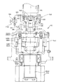
図10、図11に他の構成例を示す。 10 and 11 show other configuration examples.
この図10、図11の実施形態では、電動モータM2のモータ軸244に継軸245を介してセンタシャフト247が連結され、このセンタシャフト247が出力側減速段242を貫通して該出力側減速段242の出力軸264Aの内側にまで延在されている。流体ブレーキ機構FB2は、このセンタシャフト247と出力側減速段242の出力軸264Aとの間に介在されている。即ち、センタシャフト247の側に複数のセンタシャフト側プレート(出力軸側からの強制駆動回転が伝達される回転部としての第1プレート)267が植設されると共に、出力軸264Aの側にも、センタシャフト側プレート267より遅く回転する複数の出力側プレート(第2プレート)268が植設され、粘性流体(液体)を介してそれぞれプレート267、268が軸方向に交互に配置されている。減速機G2の減速機構の基本構成は先の実施形態と同様である。
10 and 11, the
この実施形態に係る構成によれば、先の図8、図9の実施形態に比べて流体ブレーキ機構FB2の低速側が出力側減速段242の出力軸264Aとされている。そのため、出力側減速段242の十分多い潤滑油と十分大きな熱容量を有する出力軸264A自体が流体ブレーキ機構FB2で発生する熱を良好に吸収するというメリットが得られる。したがって、流体ブレーキ機構FB2の温度上昇をより抑えることができ、長時間に亘って強風が吹き荒れるような状況においても安定したブレーキ作用を得ることができる。
According to the configuration of this embodiment, the low-speed side of the fluid brake mechanism FB2 is the
更に、流体ブレーキ機構FB2が減速装置214の比較的下側に配置されていることから、該流体ブレーキ機構FB2の発熱によって温度が上昇した出力側減速段242の潤滑油は比重が軽くなって上部に昇るため、自然対流による温度の拡散・発散も良好に行なわれる。そのため、総合的に極めて高いロバスト性を確保することができ、天候等の不確定な変動に対して、電動モータM2、ひいては風力発電システム自体の破壊や損傷からより免れることができる。
Further, since the fluid brake mechanism FB2 is disposed on the relatively lower side of the speed reducer 214, the lubricating oil in the output side
図12、図13に更に他の実施形態を示す。 12 and 13 show still another embodiment.
この実施形態における減速機G3は、単純遊星歯車減速機構のプリステージ(入力側減速段)370と内接噛合遊星歯車減速機構のメイン減速機構(出力側減速段)371とが平行軸歯車セット(中間減速段)372によって連結された構成とされている。 In the speed reducer G3 in this embodiment, a pre-stage (input-side reduction stage) 370 of a simple planetary gear reduction mechanism and a main reduction mechanism (output-side reduction stage) 371 of an intermeshing planetary gear reduction mechanism are parallel shaft gear sets ( The intermediate speed reduction stage) 372 is connected.
プリステージ370は、太陽歯車375と、該太陽歯車375に外接噛合する遊星歯車376と、該遊星歯車376が内接噛合する内歯歯車377と、を備える。太陽歯車375は、電動モータM3のモータ軸344にキー373を介して被せられた中央筒体374の端部内周に形成された内歯374Aと噛合しており、該モータ軸344と一体的に回転する。このプリステージ370は、太陽歯車入力、内歯歯車固定、キャリア出力の態様で組み込まれており、モータ軸344及び太陽歯車375が回転することによって遊星歯車376が回転すると、該遊星歯車376の公転成分がキャリアと一体化された出力軸364から出力される構成とされている。
The
平行軸歯車セット372は、プリステージ370の出力軸364に組み込まれた1個のスパーピニオン(又はヘリカルピニオン)378と、該スパーピニオン378と同時に噛合する3個のスパーギヤ(又はヘリカルギヤ)379とで構成されている。
The parallel shaft gear set 372 is composed of one spar pinion (or helical pinion) 378 incorporated in the
メイン減速機構371は、いわゆる振分タイプの内接噛合遊星歯車減速機構であり、3個のスパーギヤ379によってそれぞれ回転される3本の(1個のみ表示)偏心体軸383と、それぞれの偏心体軸383に組み込まれ各偏心体軸383に対して同位相で偏心している偏心体346A、348Aと、各偏心体346A、348Aに係合している外歯歯車350A、352Aと、該外歯歯車350A、352Aが内接噛合している内歯歯車354Aとで主に構成されている。
The main
このメイン減速機構371では、外歯歯車350A、352Aが、(前記実施形態のように中央に配置された偏心体246A、248Aによって揺動回転するのではなく)3本の偏心体軸383に同位相で組み込まれた偏心体346A、348Aが同時に同一の回転速度で回転することによって揺動回転する。内歯歯車354はケーシング388と一体化されて固定されており、外歯歯車350A、352Aと内歯歯車354との相対回転は、3本の偏心体軸383の軸心O周りの公転成分としてキャリア体385から取り出される。キャリア体385は、スプライン386を介して出力軸364Aと一体化されている。出力軸364Aには出力軸ピニオン324が一体的に形成されている。
In the main
この実施形態では、減速機G3がこのような減速機構を有し、ヴィスカスカップリング構造の流体ブレーキ機構FB3がプリステージ370の内歯歯車377とモータ軸344との間に配置されている。即ち、モータ軸344にはキー373を介して該モータ軸343と一体的に回転する中央筒体374が組み込まれている。中央筒体374には、モータ軸側プレート(出力軸側からの強制駆動回転が伝達される回転部としての第1プレート)367が複数植設されている。一方内歯歯車377は、ボルト389によってプリステージ370のケーシング390に固定されている。内歯歯車377は、軸方向モータ側に延在されており、この延在された部分に内歯歯車側プレート(固定状態の第2プレート)368が複数植設され、モータ軸側プレート367と互いに軸方向に交互に重なり合っている。両プレート367、368の間には、粘性流体(液体)が封入されており、ヴィスカスカップリング構造を形成している。
In this embodiment, the speed reducer G3 has such a speed reduction mechanism, and the fluid brake mechanism FB3 having a Viscous coupling structure is disposed between the
流体ブレーキ機構FB3の周辺には、冷却機能を兼ねたプリステージ370の潤滑油が充填されている。このため、結局、この流体ブレーキ機構FB3のモータ軸側プレート367と内歯歯車側プレート368は、モータ軸344の回転速度(プリステージ370の入力軸回転速度)に相当する相対回転速度にて互いに対向されていることになる。
The periphery of the fluid brake mechanism FB3 is filled with lubricating oil for the
この構成によっても、前述した実施形態とほぼ同様の作用効果を得ることができる。加えて、この実施形態では、流体ブレーキ機構FB3は固定メンバであるプリステージ370のケーシング390と電動モータM3のモータ軸344との間に介在されているため、流体ブレーキ機構FB3に大きなトルクが掛かったとしても、結果としてこれを「発電ユニット12」という極めて大きな質量を有するメンバで安定的に受け止めることができる。これは、熱の拡散という面でも有利である。この結果、極めて高いロバスト性を確保することができる。
Also with this configuration, it is possible to obtain substantially the same operational effects as in the above-described embodiment. In addition, in this embodiment, since the fluid brake mechanism FB3 is interposed between the
ヴィスカスカップリング構造の流体ブレーキ機構としては、更に、例えば図14、図15に示されるような構成とすることもできる。 As a fluid brake mechanism having a viscus coupling structure, for example, a configuration as shown in FIGS. 14 and 15 may be employed.
この実施形態においては、電動モータM4のモータ軸444と継カバー490との間にヴィスカスカップリング構造の流体ブレーキ機構FB4を配置すると共に、減速機G4を4段構成の単純遊星歯車減速機構470、491、492、493で構成している。
In this embodiment, a fluid brake mechanism FB4 having a Viscus coupling structure is disposed between the motor shaft 444 of the electric motor M4 and the joint cover 490, and the reduction gear G4 is a simple planetary
モータ軸444の外周には、キー473を介してモータ軸444と一体的に回転する中央筒体474が被せられ、該中央筒体474に流体ブレーキ機構FB4のモータ軸側プレート(出力軸側からの強制駆動回転が伝達される回転部としての第1プレート)467が植設されている。又、継カバー490には、リングメンバ494がボルト495を介して固定され、該リングメンバ494にケーシング側プレート(固定状態の第2プレート)468が複数植設されている。モータ軸側プレート467とケーシング側プレート468とが閉じられた空間内に封入された粘性流体(液体)を介して互いに交互に重なり合うことでヴィスカスカップリング構造を構成している。
The outer periphery of the motor shaft 444 is covered with a
なお、この実施形態では、継ケーシング490内に給油管490aを介してグリースを封入するようにしており、このグリースがヴィスカスカップリング構造に使用する粘性流体としても機能している。これにより、継ケーシング490内のグリース全体を該ヴィスカスカップリング構造に使用する粘性流体として利用できるので、熱容量的に有利である。しかし、勿論、両グリースの特性をそれぞれに適正に選択したもので構成しても良い。この場合は、両者が混合しないように流体ブレーキ機構FB4を密封度をより高めるように構成すると良い。
In this embodiment, grease is sealed in the joint casing 490 via an
流体ブレーキ機構FB4の作用効果としては、モータ軸444と固定メンバである継カバー490との間にモータ軸側プレート467及びケーシング側プレート468が植設されているため、定性的に前記実施形態と同様の作用効果が得られる。
The operational effect of the fluid brake mechanism FB4 is that the motor
この実施形態では、減速機G4として公知の単純遊星歯車減速機構の減速機G4がそのまま流用でき、電動モータM4と減速機G4との間に継ケーシング490を介在させ、この継ケーシング490内に上述した構成の流体ブレーキ機構FB4を配置するだけで良いため、設計変更が容易である。 In this embodiment, a speed reducer G4 of a simple planetary gear speed reduction mechanism known as the speed reducer G4 can be used as it is, and a joint casing 490 is interposed between the electric motor M4 and the speed reducer G4, and the above-described joint casing 490 has the above-mentioned. Since it is only necessary to arrange the fluid brake mechanism FB4 having the above-described configuration, the design can be easily changed.
図16に、本発明の更に他の実施形態の一例を示す。 FIG. 16 shows an example of still another embodiment of the present invention.
この実施形態でも、先の実施形態と実質的に同一の部位については、下2桁が同一の符号が付されている。この実施形態では、流体ブレーキ機構FB5として、この種の減速機G3において通常備えられているプランジャポンプ596の吐出圧を利用するようにしている。
In this embodiment as well, the same reference numerals in the last two digits are assigned to parts that are substantially the same as in the previous embodiment. In this embodiment, as the fluid brake mechanism FB5, the discharge pressure of the
具体的には、プランジャポンプ596の吐出配管597に適正な絞り量のオリフィス(絞り弁)596を追加するだけである。プランジャポンプ596自体は公知のもので、図示せぬピストンにストロークを与えるカム598を備えている。カム598は、入力側減速段540の出力軸564の回転と共に回転し、該出力軸564の回転速度に応じた吐出圧を吐出配管597側に吐出する。
Specifically, an orifice (throttle valve) 596 having an appropriate throttle amount is simply added to the
この実施形態では、この吐出配管597の途中に適正な絞り量のオリフィス599が追加されているため、入力側減速段540の出力軸564の回転速度が大きくなると、オリフィス599には吐出配管597を流れる潤滑油の通過速度の2乗に比例した抵抗が発生することになる。そのため、この構造によっても、出力軸564A(あるいは出力軸564)の回転速度の2乗に比例した制動負荷を得ることができるようになり、該出力軸564Aの回転速度の上昇に伴って、該回転速度の上昇よりも大きな比率で回転抵抗が増大し、有効に機能する流体ブレーキ機構FB5を構成することができる。
In this embodiment, an
なお、ポンプは、必ずしもプランジャポンプである必要はなく、いわゆる内接歯車型のポンプであっても良い。 The pump is not necessarily a plunger pump, and may be a so-called internal gear type pump.
以上例示された、「液体を媒体とした」流体ブレーキ機構FB1〜FB5は、いずれも液体が流体として機能するときに本来的に有する性質(圧縮抵抗、変形抵抗、撹拌抵抗、粘性抵抗、剪断抵抗、通過抵抗等)を利用したものであり、固体と固体の摩擦抵抗を利用したものではないため、劣悪環境の下でも確実な制動トルクを得ることができる。また、制動トルク発生のために特別な電源を必要とせず、電気的な制御指令の発生も必要としない。従って、極めて信頼性の高い制動トルクを簡易な構成で発生させることができる。 The fluid brake mechanisms FB1 to FB5, which are exemplified above, have inherent properties when the liquid functions as a fluid (compression resistance, deformation resistance, stirring resistance, viscosity resistance, shear resistance). , Passage resistance, etc.), and not solid-solid frictional resistance, so that a reliable braking torque can be obtained even in a poor environment. Further, no special power source is required for generating braking torque, and no generation of electrical control commands is required. Therefore, extremely reliable braking torque can be generated with a simple configuration.
なお、上記実施形態においては、風力発電システムのヨー駆動用の動力伝達装置に本発明を適用した例が示されていた。しかしながら、本発明の適用は、風力発電システムのヨー駆動用の動力伝達装置に限定されるものではなく、例えば風力発電システムのピッチ駆動用の動力伝達装置に適用することもでき、更には、太陽光発電システムの受光パネルを太陽の方向に向くように駆動する動力伝達装置等に適用することもできる。即ち、風力、太陽光等の自然エネルギを回収するシステムにおける風車ブレードや受光パネル等のエネルギ回収メンバを、例えばそのときの最適回収方向に向けさせるために使用される動力伝達装置に同様に適用でき、自然の巨大なエネルギから電動モータを保護すると共に、ひいては風力発電システムや太陽光発電システム全体を有効に保護することができる。 In the above embodiment, an example in which the present invention is applied to a power transmission device for yaw drive of a wind power generation system is shown. However, the application of the present invention is not limited to the power transmission device for the yaw drive of the wind power generation system, and can be applied to, for example, the power transmission device for the pitch drive of the wind power generation system. The present invention can also be applied to a power transmission device that drives the light receiving panel of the photovoltaic system so as to face the sun. That is, it can be similarly applied to a power transmission device used for directing energy recovery members such as windmill blades and light receiving panels in a system for recovering natural energy such as wind power and sunlight, for example, in an optimal recovery direction at that time. In addition to protecting the electric motor from natural enormous energy, the wind power generation system and the entire solar power generation system can be effectively protected.
また、本発明に係る流体ブレーキ機構自体も、上記例のみに限定されるものではなく、2以上の流体ブレーキ機構の併用についても、上記例に限定されるものではない。例えば、ヴィスカスカップリング構造を利用した制動とプランジャポンプを利用した制動とを併用するようにしても良い。2以上の流体ブレーキ機構を併用する場合、それぞれの流体ブレーキ機構での特性の相乗的効果を得ることができるようになるため、意図する制動特性を設計し易くなるというメリットが得られる。 Further, the fluid brake mechanism itself according to the present invention is not limited to the above example, and the combined use of two or more fluid brake mechanisms is not limited to the above example. For example, braking using a viscus coupling structure and braking using a plunger pump may be used in combination. When two or more fluid brake mechanisms are used in combination, a synergistic effect of the characteristics of each fluid brake mechanism can be obtained, so that an advantage that it is easy to design an intended braking characteristic can be obtained.
減速機との組み合わせも、上記例に限定されず、例えば、図14の減速機に対して、図10及び図11のヴィスカスカップリングを適用しても良い。更には、これ以外の構成の減速機に適用しても良い。 The combination with the speed reducer is not limited to the above example. For example, the Viscous coupling shown in FIGS. 10 and 11 may be applied to the speed reducer shown in FIG. Furthermore, the present invention may be applied to a speed reducer having a configuration other than this.
本発明は、風力、太陽光等の自然エネルギを回収するシステムにおける風車ブレードや受光パネル等のエネルギ回収メンバを、例えばそのときの最適回収方向に向けさせるために使用される動力伝達装置に適用できる。 INDUSTRIAL APPLICABILITY The present invention can be applied to a power transmission device used to direct energy recovery members such as windmill blades and light receiving panels in a system for recovering natural energy such as wind power and sunlight, for example, in an optimal recovery direction at that time. .
Mo〜M5…電動モータ
Go〜G5…減速機
FBo〜FB5…流体ブレーキ機構
10…風力発電システム
12…発電ユニット
14…ヨー駆動用の駆動装置(動力伝達装置)
16…ピッチ駆動用の駆動装置
18…ノーズコーン
20…風車ブレード
24…ヨー駆動用ピニオン
26…ヨーベアリング
28…リングギヤ部
36…軸心
40…入力側減速段
42…出力側減速段
44…入力軸
46、48…偏心体
50、52…外歯歯車
54…内歯歯車
56…ケーシング
58…外ピン
60…内ピン
62…内ローラ
64…(入力側減速段の)出力軸
64A…(出力側減速段の)出力軸
70、72…遮蔽板
74…仕切り板
167…入力側プレート
168…出力側プレート
596…プランジャポンプ
597…吐出配管
599…オリフィス
Mo to M5 Electric motor Go to G5 Reducer FBo to FB5
DESCRIPTION OF
Claims (10)
電動モータと、
該電動モータと連結され、出力軸を備えた減速機と、
前記電動モータと減速機の出力軸との間の動力伝達経路に対して付設され、前記出力軸の回転速度が上昇したときに、該動力伝達経路の回転抵抗を増大させる液体を媒体とした流体ブレーキ機構と、
を備えたことを特徴とする自然エネルギ回収システムの動力伝達装置。 A power transmission device for a natural energy recovery system used in a system for recovering natural energy such as wind power and sunlight,
An electric motor;
A speed reducer connected to the electric motor and provided with an output shaft;
Fluid that is attached to a power transmission path between the electric motor and the output shaft of the speed reducer, and that increases the rotational resistance of the power transmission path when the rotational speed of the output shaft increases, is a fluid. A brake mechanism;
A power transmission device for a natural energy recovery system.
前記減速機が、2段以上の減速段で構成され、且つ、入力側の減速段に前記流体ブレーキ機構が付設されている
ことを特徴とする自然エネルギ回収システムの動力伝達装置。 In claim 1,
The power transmission device for a natural energy recovery system, wherein the speed reducer includes two or more speed reduction stages, and the fluid brake mechanism is attached to the input speed reduction stage.
前記流体ブレーキ機構が、前記出力軸側からの強制駆動回転が伝達される回転部が前記液体中に配設され、該回転部の回転速度の上昇に応じて該回転部が前記液体から受ける回転抵抗が増大する構成とされている
ことを特徴とする自然エネルギ回収システムの動力伝達装置。 3. The fluid brake mechanism according to claim 1, wherein the fluid brake mechanism includes a rotating portion in the liquid to which forced driving rotation from the output shaft side is transmitted, and the rotating portion according to an increase in rotational speed of the rotating portion. A power transmission device for a natural energy recovery system, wherein the rotational resistance received from the liquid increases.
前記流体ブレーキ機構が、前記回転部としての第1プレートと、該第1プレートと同軸に配置された第2プレートが、前記液体中に軸方向に交互に配置されたヴィスカスカップリングである
ことを特徴とする自然エネルギ回収システムの動力伝達装置。 In claim 3,
The fluid brake mechanism is a viscous coupling in which a first plate as the rotating portion and a second plate arranged coaxially with the first plate are alternately arranged in the liquid in the axial direction. A power transmission device for a natural energy recovery system.
前記第1プレートが電動モータのモータ軸またはこれと一体的に回転する部材に設けられ、前記第2プレートが前記減速機のケーシングまたはこれと一体化された固定部材に設けられている
ことを特徴とする自然エネルギ回収システムの動力伝達装置。 In claim 4,
The first plate is provided on a motor shaft of an electric motor or a member that rotates integrally therewith, and the second plate is provided on a casing of the speed reducer or a fixed member integrated with the same. A power transmission device for a natural energy recovery system.
前記第1プレートが電動モータのモータ軸またはこれと一体的に回転する部材に設けられ、前記第2プレートが該第1プレートより遅く回転する回転部材に設けられている
ことを特徴とする自然エネルギ回収システムの動力伝達装置。 In claim 4,
The first plate is provided on a motor shaft of an electric motor or a member that rotates integrally therewith, and the second plate is provided on a rotating member that rotates later than the first plate. Power transmission device for recovery system.
前記減速機が、偏心揺動する複数の外歯歯車と、該外歯歯車が内接噛合する内歯歯車と、を有する内接噛合遊星歯車減速機構を備え、
前記流体ブレーキ機構が、前記回転部としての前記複数の外歯歯車と、該外歯歯車の軸方向外側に配置され該複数の外歯歯車と前記内歯歯車との間の空間を閉塞する2枚の遮蔽板と、前記複数のそれぞれの外歯歯車の間に配置され該閉塞された空間内の潤滑油が軸方向に相互に行き来するのを制限する仕切板と、を備えた構成とされた
ことを特徴とする自然エネルギ回収システムの動力伝達装置。 In claim 3,
The speed reducer includes an internally meshing planetary gear speed reduction mechanism having a plurality of externally geared eccentric gears and an internally geared gear that is internally meshed with the external gear,
The fluid brake mechanism is disposed outside the plurality of external gears as the rotating portion and in the axial direction of the external gear, and closes a space between the plurality of external gears and the internal gear. A plurality of shielding plates, and a partition plate disposed between the plurality of external gears for restricting the lubricating oil in the closed space from going back and forth in the axial direction. A power transmission device for a natural energy recovery system.
前記仕切板に、前記潤滑油が軸方向に相互に行き来するのを制限する程度を規定するための貫通孔が形成されている
ことを特徴とする自然エネルギ回収システムの動力伝達装置。 In claim 7,
A through hole is provided in the partition plate for defining the degree of restriction of the lubricating oil from going back and forth in the axial direction. A power transmission device for a natural energy recovery system.
前記仕切板の熱膨張率が、前記外歯歯車及び内歯歯車の熱膨張率より大きい
ことを特徴とする自然エネルギ回収システムの動力伝達装置。 In claim 7 or 8,
The power transmission device for a natural energy recovery system, wherein a thermal expansion coefficient of the partition plate is larger than thermal expansion coefficients of the external gear and the internal gear.
前記流体ブレーキ機構が、前記減速機の潤滑油を巡回させるためのポンプの吐出配管に絞り弁を介在させた構成とされた
ことを特徴とする自然エネルギ回収システムの動力伝達装置。 In any one of Claims 1-9,
The power transmission device of a natural energy recovery system, wherein the fluid brake mechanism is configured such that a throttle valve is interposed in a discharge pipe of a pump for circulating lubricating oil of the speed reducer.
Priority Applications (3)
| Application Number | Priority Date | Filing Date | Title |
|---|---|---|---|
| JP2008215975A JP5221246B2 (en) | 2008-08-25 | 2008-08-25 | Power transmission device for natural energy recovery system |
| CN200980132787.4A CN102132040B (en) | 2008-08-25 | 2009-08-20 | Power transmission device of natural energy recovery system |
| PCT/JP2009/064591 WO2010024181A1 (en) | 2008-08-25 | 2009-08-20 | Power transmission device of natural energy recovery system |
Applications Claiming Priority (1)
| Application Number | Priority Date | Filing Date | Title |
|---|---|---|---|
| JP2008215975A JP5221246B2 (en) | 2008-08-25 | 2008-08-25 | Power transmission device for natural energy recovery system |
Publications (2)
| Publication Number | Publication Date |
|---|---|
| JP2010048244A true JP2010048244A (en) | 2010-03-04 |
| JP5221246B2 JP5221246B2 (en) | 2013-06-26 |
Family
ID=41721349
Family Applications (1)
| Application Number | Title | Priority Date | Filing Date |
|---|---|---|---|
| JP2008215975A Expired - Fee Related JP5221246B2 (en) | 2008-08-25 | 2008-08-25 | Power transmission device for natural energy recovery system |
Country Status (3)
| Country | Link |
|---|---|
| JP (1) | JP5221246B2 (en) |
| CN (1) | CN102132040B (en) |
| WO (1) | WO2010024181A1 (en) |
Cited By (7)
| Publication number | Priority date | Publication date | Assignee | Title |
|---|---|---|---|---|
| JP2010216355A (en) * | 2009-03-16 | 2010-09-30 | Sumitomo Heavy Ind Ltd | Reduction gear for yaw driving device for wind power generator |
| JP2012031827A (en) * | 2010-08-02 | 2012-02-16 | Sumitomo Heavy Ind Ltd | Reduction gear apparatus of wind power generation equipment |
| JP2012092755A (en) * | 2010-10-27 | 2012-05-17 | Sumitomo Heavy Ind Ltd | Reduction gear device used in wind turbine generator system and yaw drive device of wind turbine generator system |
| JP2012140885A (en) * | 2010-12-28 | 2012-07-26 | Sumitomo Heavy Ind Ltd | Reduction gear to be used in wind power generating facility |
| JP2012180809A (en) * | 2011-03-02 | 2012-09-20 | Sumitomo Heavy Ind Ltd | Reduction gear of wind power generation equipment and reduction gear having output pinion |
| EP3412907A1 (en) * | 2017-06-07 | 2018-12-12 | S.B. Patent Holding ApS | Multi-surface yaw braking system for a wind turbine |
| US11092134B2 (en) * | 2017-03-03 | 2021-08-17 | Wobben Properties Gmbh | Adjustment unit for azimuth adjustment and/or pitch adjustment of a wind turbine, and method |
Families Citing this family (3)
| Publication number | Priority date | Publication date | Assignee | Title |
|---|---|---|---|---|
| ITBO20110490A1 (en) * | 2011-08-05 | 2013-02-06 | Bonfiglioli Riduttori Spa | WIND GENERATOR |
| JP2014163506A (en) * | 2013-02-27 | 2014-09-08 | Sumitomo Heavy Ind Ltd | Planetary gear speed reduction device and method for manufacturing the same |
| TWI642841B (en) * | 2017-05-23 | 2018-12-01 | 劉文欽 | Power converter with rotational force feedback control speed |
Citations (2)
| Publication number | Priority date | Publication date | Assignee | Title |
|---|---|---|---|---|
| JPS649062A (en) * | 1987-06-29 | 1989-01-12 | Mitsubishi Electric Corp | Motor driven power steering device |
| JP2005113899A (en) * | 2003-09-19 | 2005-04-28 | Nabtesco Corp | Yaw drive method and device for wind power generator |
Family Cites Families (1)
| Publication number | Priority date | Publication date | Assignee | Title |
|---|---|---|---|---|
| JP2005061519A (en) * | 2003-08-12 | 2005-03-10 | Nabtesco Corp | Reduction gear used in yaw driving device of wind power generator |
-
2008
- 2008-08-25 JP JP2008215975A patent/JP5221246B2/en not_active Expired - Fee Related
-
2009
- 2009-08-20 CN CN200980132787.4A patent/CN102132040B/en not_active Expired - Fee Related
- 2009-08-20 WO PCT/JP2009/064591 patent/WO2010024181A1/en active Application Filing
Patent Citations (2)
| Publication number | Priority date | Publication date | Assignee | Title |
|---|---|---|---|---|
| JPS649062A (en) * | 1987-06-29 | 1989-01-12 | Mitsubishi Electric Corp | Motor driven power steering device |
| JP2005113899A (en) * | 2003-09-19 | 2005-04-28 | Nabtesco Corp | Yaw drive method and device for wind power generator |
Cited By (7)
| Publication number | Priority date | Publication date | Assignee | Title |
|---|---|---|---|---|
| JP2010216355A (en) * | 2009-03-16 | 2010-09-30 | Sumitomo Heavy Ind Ltd | Reduction gear for yaw driving device for wind power generator |
| JP2012031827A (en) * | 2010-08-02 | 2012-02-16 | Sumitomo Heavy Ind Ltd | Reduction gear apparatus of wind power generation equipment |
| JP2012092755A (en) * | 2010-10-27 | 2012-05-17 | Sumitomo Heavy Ind Ltd | Reduction gear device used in wind turbine generator system and yaw drive device of wind turbine generator system |
| JP2012140885A (en) * | 2010-12-28 | 2012-07-26 | Sumitomo Heavy Ind Ltd | Reduction gear to be used in wind power generating facility |
| JP2012180809A (en) * | 2011-03-02 | 2012-09-20 | Sumitomo Heavy Ind Ltd | Reduction gear of wind power generation equipment and reduction gear having output pinion |
| US11092134B2 (en) * | 2017-03-03 | 2021-08-17 | Wobben Properties Gmbh | Adjustment unit for azimuth adjustment and/or pitch adjustment of a wind turbine, and method |
| EP3412907A1 (en) * | 2017-06-07 | 2018-12-12 | S.B. Patent Holding ApS | Multi-surface yaw braking system for a wind turbine |
Also Published As
| Publication number | Publication date |
|---|---|
| WO2010024181A1 (en) | 2010-03-04 |
| CN102132040A (en) | 2011-07-20 |
| CN102132040B (en) | 2014-07-02 |
| JP5221246B2 (en) | 2013-06-26 |
Similar Documents
| Publication | Publication Date | Title |
|---|---|---|
| JP5221246B2 (en) | Power transmission device for natural energy recovery system | |
| TWI391583B (en) | Power transmission device and manufacturing method thereof | |
| US20120074712A1 (en) | Multi-rotor fluid turbine drive with speed converter | |
| US5140170A (en) | Power generating system | |
| EP3173667B1 (en) | Transmission | |
| CN101680430B (en) | Variable ratio gear | |
| EP2276924B1 (en) | Method for operating a wind energy converter, control device for a wind energy converter, and wind energy converter | |
| CA2689235A1 (en) | Variable ratio transmission | |
| JP5654949B2 (en) | Power transmission device for wind power generation equipment | |
| JP4722410B2 (en) | Wind power generator | |
| CN102454545B (en) | Speed reducer for wind power generation equipment, and yaw drive device of wind power generation equipment | |
| US9989122B2 (en) | Planetary gear device and jet engine with a planetary gear device | |
| JP5877222B2 (en) | Power transmission device for wind power generation equipment | |
| WO2005012763A1 (en) | Drive train for a renewable-energy generating machine | |
| CN102562458B (en) | Reduction gear used in wind power generating equipment | |
| WO2013035865A1 (en) | Step-up gear for wind-powered electricity generation | |
| JP5352510B2 (en) | Wind speed booster | |
| GB2468863A (en) | Vertical Axis Wind Turbine with non-newtonian fluid damped auto pitching and air brake | |
| JP5917070B2 (en) | Wind speed booster with locked train mechanism | |
| JP5836036B2 (en) | Wind speed booster | |
| JP2013057346A (en) | Speed increasing gearbox for wind power generation | |
| CA2741101C (en) | Dynamic ratio speed increaser for windmills and similar applications | |
| JP5836035B2 (en) | Wind speed booster | |
| WO2013038495A1 (en) | Step-up gear for wind-powered electricity generation | |
| CN102275803A (en) | Integral type disc brake stepless speed regulation elevator for mine |
Legal Events
| Date | Code | Title | Description |
|---|---|---|---|
| A621 | Written request for application examination |
Free format text: JAPANESE INTERMEDIATE CODE: A621 Effective date: 20110801 |
|
| TRDD | Decision of grant or rejection written | ||
| A01 | Written decision to grant a patent or to grant a registration (utility model) |
Free format text: JAPANESE INTERMEDIATE CODE: A01 Effective date: 20130305 |
|
| A61 | First payment of annual fees (during grant procedure) |
Free format text: JAPANESE INTERMEDIATE CODE: A61 Effective date: 20130307 |
|
| FPAY | Renewal fee payment (event date is renewal date of database) |
Free format text: PAYMENT UNTIL: 20160315 Year of fee payment: 3 |
|
| R150 | Certificate of patent or registration of utility model |
Free format text: JAPANESE INTERMEDIATE CODE: R150 |
|
| LAPS | Cancellation because of no payment of annual fees |