JP2010047891A - Device for spinning pre-treating machine having drawing mechanism for drawing fiber material of twisted fiber form or in the pre-treating machine - Google Patents
Device for spinning pre-treating machine having drawing mechanism for drawing fiber material of twisted fiber form or in the pre-treating machine Download PDFInfo
- Publication number
- JP2010047891A JP2010047891A JP2009171290A JP2009171290A JP2010047891A JP 2010047891 A JP2010047891 A JP 2010047891A JP 2009171290 A JP2009171290 A JP 2009171290A JP 2009171290 A JP2009171290 A JP 2009171290A JP 2010047891 A JP2010047891 A JP 2010047891A
- Authority
- JP
- Japan
- Prior art keywords
- sensor
- spinning
- sliver
- distance sensor
- distance
- Prior art date
- Legal status (The legal status is an assumption and is not a legal conclusion. Google has not performed a legal analysis and makes no representation as to the accuracy of the status listed.)
- Granted
Links
Images


Classifications
-
- G—PHYSICS
- G01—MEASURING; TESTING
- G01B—MEASURING LENGTH, THICKNESS OR SIMILAR LINEAR DIMENSIONS; MEASURING ANGLES; MEASURING AREAS; MEASURING IRREGULARITIES OF SURFACES OR CONTOURS
- G01B11/00—Measuring arrangements characterised by the use of optical techniques
- G01B11/02—Measuring arrangements characterised by the use of optical techniques for measuring length, width or thickness
- G01B11/026—Measuring arrangements characterised by the use of optical techniques for measuring length, width or thickness by measuring distance between sensor and object
-
- D—TEXTILES; PAPER
- D01—NATURAL OR MAN-MADE THREADS OR FIBRES; SPINNING
- D01G—PRELIMINARY TREATMENT OF FIBRES, e.g. FOR SPINNING
- D01G23/00—Feeding fibres to machines; Conveying fibres between machines
- D01G23/06—Arrangements in which a machine or apparatus is regulated in response to changes in the volume or weight of fibres fed, e.g. piano motions
-
- D—TEXTILES; PAPER
- D01—NATURAL OR MAN-MADE THREADS OR FIBRES; SPINNING
- D01H—SPINNING OR TWISTING
- D01H5/00—Drafting machines or arrangements ; Threading of roving into drafting machine
- D01H5/18—Drafting machines or arrangements without fallers or like pinned bars
- D01H5/32—Regulating or varying draft
- D01H5/38—Regulating or varying draft in response to irregularities in material ; Measuring irregularities
-
- G—PHYSICS
- G01—MEASURING; TESTING
- G01B—MEASURING LENGTH, THICKNESS OR SIMILAR LINEAR DIMENSIONS; MEASURING ANGLES; MEASURING AREAS; MEASURING IRREGULARITIES OF SURFACES OR CONTOURS
- G01B11/00—Measuring arrangements characterised by the use of optical techniques
- G01B11/02—Measuring arrangements characterised by the use of optical techniques for measuring length, width or thickness
- G01B11/06—Measuring arrangements characterised by the use of optical techniques for measuring length, width or thickness for measuring thickness ; e.g. of sheet material
-
- G—PHYSICS
- G01—MEASURING; TESTING
- G01B—MEASURING LENGTH, THICKNESS OR SIMILAR LINEAR DIMENSIONS; MEASURING ANGLES; MEASURING AREAS; MEASURING IRREGULARITIES OF SURFACES OR CONTOURS
- G01B5/00—Measuring arrangements characterised by the use of mechanical techniques
- G01B5/02—Measuring arrangements characterised by the use of mechanical techniques for measuring length, width or thickness
- G01B5/06—Measuring arrangements characterised by the use of mechanical techniques for measuring length, width or thickness for measuring thickness
- G01B5/068—Measuring arrangements characterised by the use of mechanical techniques for measuring length, width or thickness for measuring thickness of objects while moving
Abstract
Description
本発明は、撚線形態の繊維材料を引き伸ばす練篠機構を有する特にカード機、練篠フレーム、コーミング機械もしくはフライヤである紡績用前処理機のためにまたは該前処理機において少なくとも一本の繊維スライバの断面積および/または質量を連続的に計測するための装置であって、該装置は、一方のローラは移動不能に配置され且つ他方のローラは該一方のローラから離間移動可能に配置されると共に相互に当接して押圧されるべく配置された一対の測定ローラを有し、且つ、該装置は、上記各ローラの内の一方のローラのための保持要素に対して結合された相対表面(検知対象表面)からの間隔を測定する非接触式間隔センサを有するという装置に関する。 The present invention relates to a spinning pretreatment machine, in particular a carding machine, a knitting frame, a combing machine or a flyer, having at least one fiber with a drawing mechanism for drawing fiber material in the form of stranded wire. A device for continuously measuring the cross-sectional area and / or mass of a sliver, wherein one device is arranged such that one roller is immovable and the other roller is arranged so as to be movable away from the one roller. And a pair of measuring rollers arranged to abut against each other and to be pressed against each other, and the device is a relative surface coupled to a holding element for one of the rollers The present invention relates to an apparatus having a non-contact type distance sensor for measuring a distance from (a surface to be detected).
実際問題として、特に紡績用前処理機へと導入される一本以上の繊維スライバの"むら"を均一化する目的で、繊維スライバの太さを測定することは通常的である。斯かる種類の測定はまた、引き伸ばされた材料の品質制御のために上記機械からの出口においても好適である。上記品質制御に加え、繊維スライバの密度もしくは太さに関する測定値は、所定の質量変動制限値を超過して高品質製品がもはや獲得されない場合に、上記機械を作動停止させるためにも用いられる。 As a practical matter, it is common to measure the thickness of the fiber sliver, particularly for the purpose of homogenizing the “unevenness” of one or more fiber slivers introduced into the spinning pre-processing machine. This type of measurement is also suitable at the exit from the machine for quality control of the stretched material. In addition to the quality control, measurements related to the density or thickness of the fiber sliver are also used to shut down the machine when a predetermined mass variation limit is exceeded and high quality products are no longer obtained.
練篠機構を有する公知の装置(特許文献1)において、繊維スライバは、移動不能ローラと、該ローラに対して押圧され得る可動ローラとの間に案内される(引出しローラおよび検知対象ローラ)。上記引出しローラおよび検知対象ローラは、夫々のシャフト上に固定される。上記引出しローラは、そのシャフトにより、第1軸受ハウジング内に回転可能に取付けられる。該軸受ハウジングは、練篠フレームにおいて移動不能に配置される。上記検知対象ローラは、そのシャフト上で、第2軸受ハウジング内に回転可能に取付けられる。上記第2軸受ハウジングは、該軸受ハウジングが方向Aにおける偏位を受け得る様に練篠フレームに配置される。上記偏位は、圧縮スプリングの力に抗して生ずる。上記圧縮スプリングは、上記検知対象ローラを上記引出しローラに対して押圧すると共に、上記練篠フレームの不動構成要素に当接して着座している。上記第2ハウジング上には、測定プレートが配置される。この測定プレートによって、変位センサに対する厳密な基準表面の存在が確保される。上記変位センサは、該変位センサと上記測定プレートとの間における間隔Bを計測する。間隔Bの変化は上記変位センサにより、電圧の変化を以てスライバ・モニタに伝達される。故に上記変位センサは、信号変換器の役割を果たす。測定済み距離として使用される上記間隔Bは、通常は非常に小さく、すなわち、十分の数ミリメートルである。上記変位センサによれば、上記引出しローラと上記検知対象ローラとの間における間隔の最小の変化でさえも計測される。上記変位センサは、上記圧縮スプリングが着座する練篠フレームの上記不動構成要素に固定される。この構成要素、および結果として上記変位センサもまた、ローラ・ニップから離間した側の空き空間であって、上記第2軸受ハウジングから所定間隔における空き空間内に配置される。しかし空間が限られる場合には、相当の空間が必要とされることは、ひとつの欠点である。これに加え、配置構成に関する負担、すなわち上記変位センサを取付けるための設置に関する負担は、欠点である。最後に、上記不動構成要素上への配置は、上記変位センサに対する特有の調節もしくは設定手順を必要とする。 In a known device having a kneading mechanism (Patent Document 1), the fiber sliver is guided between a non-movable roller and a movable roller that can be pressed against the roller (drawer roller and detection target roller). The drawing roller and the detection target roller are fixed on respective shafts. The drawing roller is rotatably mounted in the first bearing housing by its shaft. The bearing housing is disposed immovably in the training frame. The detection target roller is rotatably mounted on the shaft in the second bearing housing. The second bearing housing is disposed on the training frame so that the bearing housing can be displaced in the direction A. The displacement occurs against the force of the compression spring. The compression spring presses the roller to be detected against the pull-out roller and sits in contact with a stationary component of the training frame. A measurement plate is disposed on the second housing. This measuring plate ensures the presence of a strict reference surface for the displacement sensor. The displacement sensor measures an interval B between the displacement sensor and the measurement plate. The change in the interval B is transmitted to the sliver monitor by the displacement sensor as a voltage change. Therefore, the displacement sensor serves as a signal converter. The spacing B used as a measured distance is usually very small, i.e. a few millimeters. According to the displacement sensor, even a minimum change in the distance between the drawing roller and the detection target roller is measured. The displacement sensor is fixed to the stationary component of the training frame on which the compression spring is seated. This component, and consequently the displacement sensor, is also disposed in an empty space on the side away from the roller nip and in an empty space at a predetermined interval from the second bearing housing. However, when space is limited, the need for considerable space is a drawback. In addition to this, a burden related to the arrangement configuration, that is, a burden related to installation for mounting the displacement sensor is a drawback. Finally, placement on the stationary component requires a specific adjustment or setting procedure for the displacement sensor.
故に本発明の基礎となる課題は、冒頭に記述された種類の装置であって、言及された欠点を回避すると共に、特に空間が限られる場合に簡素な手段により間隔センサの配置を可能とし、且つ、検知対象表面に対する間隔センサの優れた結合または協働を可能にするという装置を提供するに在る。 The problem underlying the present invention is therefore a device of the kind described at the outset, which avoids the mentioned disadvantages and allows the arrangement of the distance sensor by simple means, especially when space is limited, It is also an object of the present invention to provide an apparatus that enables excellent coupling or cooperation of the distance sensor to the surface to be detected.
上記課題は、請求項1の特徴部分の特徴により解決される。
すなわち、1番目の発明によれば、撚線形態の繊維材料を引き伸ばす練篠機構を有する特にカード機、練篠フレーム、コーミング機械もしくはフライヤである紡績用前処理機のためにまたは該前処理機において少なくとも一本の繊維スライバの断面積および/または質量を連続的に計測するための装置であって、該装置は、一方のローラは移動不能に配置され且つ他方のローラは該一方のローラから離間移動可能に配置されると共に相互に当接して押圧されるべく配置された一対の測定ローラを有し、且つ、該装置は、上記各ローラの内の一方のローラのための保持要素に対して結合された対応表面(検知対象表面)からの間隔を測定する非接触式間隔センサを有するという装置において、上記間隔センサ(9、25;47;57、571、572;60)は、他方のローラ(7、8;15、16;42、43)のための保持要素(52、52b、53a、53b)に結合され、且つ、上記間隔センサ(9、25;47;57、571、572;60)および上記対応表面(53';59)は、上記各保持要素(52、52b、53a、53b)の側面であって相互に臨むという側面上に夫々配置されることを特徴とする、装置が提供される。
The above problem is solved by the features of the characterizing portion of claim 1.
That is, according to the first invention, or for a pretreatment machine for spinning which is a card machine, a knitting frame, a combing machine or a flyer, particularly having a knitting mechanism that stretches a fiber material in the form of a stranded wire. For continuously measuring the cross-sectional area and / or mass of at least one fiber sliver, wherein one of the rollers is arranged immovably and the other roller is disengaged from the one roller And a pair of measuring rollers arranged to be spaced apart and arranged to be pressed against each other, and the device comprises a holding element for one of the rollers In the apparatus having a non-contact type distance sensor for measuring a distance from a corresponding surface (surface to be detected) combined, the distance sensor (9, 25; 47; 57, 57 1 , 57 2 ; 60) The other Rollers (7, 8; 15, 16; 42, 43) holding elements for (52, 52b, 53a, 53b) are coupled to, and, the distance sensor (9, 25; 47; 57 1, 57 2 ; 60) and the corresponding surface (53 '; 59) are arranged on the side surfaces of the holding elements (52, 52b, 53a, 53b) and facing each other, respectively. A device is provided.
他方のローラのための保持要素に対して上記間隔センサを結合すると共に、その様に位置決めされた上記間隔センサと対向して上記検知対象表面を配置することにより、空間節約的な配置構成が実現される。他方のローラのための既存の保持要素に対して上記間隔センサを結合すると、構成および設置に関する簡素化が同時に好適に許容される。繊維スライバ太さを測定するために、各保持要素間で変化する間隔が好適に採用される。上記間隔センサを上記保持要素に対して機械的に一体化すると、該間隔センサの調節手順が特に洗練された様式で簡素化される。上記間隔センサおよび上記検知対象表面の配置であって、構成に関して簡素であるというこの配置は、空間節約的である。故に上記間隔センサおよび上記検知対象表面は夫々の場合、当該組み合わせが同時に幾つかの機能に資する様に、紡績用前処理機の保持要素に対して組み合わされる。 A space-saving arrangement structure is realized by coupling the distance sensor to the holding element for the other roller and arranging the detection target surface facing the distance sensor so positioned. Is done. When the distance sensor is coupled to an existing holding element for the other roller, simplification with respect to construction and installation is preferably allowed at the same time. In order to measure the fiber sliver thickness, an interval that varies between the holding elements is preferably employed. The mechanical integration of the distance sensor with respect to the holding element simplifies the adjustment procedure of the distance sensor in a particularly sophisticated manner. This arrangement of the distance sensor and the surface to be detected, which is simple in terms of construction, is space saving. Therefore, in each case, the distance sensor and the surface to be detected are combined with the holding element of the spinning pre-treatment machine so that the combination simultaneously serves several functions.
請求項2乃至75は、本発明の好適な発展例を包含する。
2番目の発明によれば、1番目の発明において、前記間隔センサは前記他方のローラのための前記保持要素に一体化されることを特徴とする。
3番目の発明によれば、1番目または2番目の発明において、前記間隔センサは前記保持要素の別体的部分として構成される。
4番目の発明によれば、1番目から3番目のいずれかの発明において、前記保持要素は前記間隔センサの少なくとも一部分と協働する一体部材として構成される。
5番目の発明によれば、1番目から4番目のいずれかの発明において、前記間隔センサの空間は、前記保持要素における陥没部(凹所)により少なくとも部分的に形成される。
6番目の発明によれば、1番目から5番目のいずれかの発明において、前記保持要素は前記ローラのための軸受要素である。
7番目の発明によれば、1番目から6番目のいずれかの発明において、前記軸受要素は移動不能な回転軸受である。
8番目の発明によれば、1番目から7番目のいずれかの発明において、前記軸受要素は移動可能な回転軸受である。
9番目の発明によれば、1番目から8番目のいずれかの発明において、前記移動可能な軸受要素はスプリング負荷される。
10番目の発明によれば、1番目から9番目のいずれかの発明において、前記軸受要素はアルミニウムで作成される。
11番目の発明によれば、1番目から10番目のいずれかの発明において、前記間隔センサは移動不能であり、且つ、前記対応表面は上記間隔センサに対して移動すべく配置される。
12番目の発明によれば、1番目から11番目のいずれかの発明において、前記間隔センサは移動すべく配置され、且つ、前記対応表面は上記間隔センサに対して移動不能である。
13番目の発明によれば、1番目から12番目のいずれかの発明において、前記対応表面は、前記各ローラの内の一方のローラのための前記保持要素の外側表面である。
14番目の発明によれば、1番目から13番目のいずれかの発明において、前記対応表面は、前記各ローラの内の一方のローラに結合された対応要素の表面である。
15番目の発明によれば、1番目から14番目のいずれかの発明において、前記対応要素は、前記各ローラの内の一方のローラのための前記保持要素に対して一体化される。
16番目の発明によれば、1番目から15番目のいずれかの発明において、前記検知対象表面は平坦である。
17番目の発明によれば、1番目から16番目のいずれかの発明において、前記検知対象表面は円滑である。
18番目の発明によれば、1番目から17番目のいずれかの発明において、前記間隔センサは電波もしくは光線を使用する距離測定センサである。
19番目の発明によれば、1番目から18番目のいずれかの発明において、前記間隔センサは誘導における変化を計測し得る。
20番目の発明によれば、1番目から19番目のいずれかの発明において、前記間隔測定デバイスは誘導式近接始動器である。
21番目の発明によれば、1番目から20番目のいずれかの発明において、前記間隔センサは誘導式変位センサである。
22番目の発明によれば、1番目から21番目のいずれかの発明において、前記誘導式変位センサはプランジャ・コイルおよびプランジャ・コアを備えて成る。
23番目の発明によれば、1番目から22番目のいずれかの発明において、光学式間隔センサ(距離測定センサ)が採用される。
24番目の発明によれば、1番目から23番目のいずれかの発明において、前記間隔センサは光センサである。
25番目の発明によれば、1番目から24番目のいずれかの発明において、前記間隔センサはレーザ・センサである。
26番目の発明によれば、1番目から25番目のいずれかの発明において、前記間隔センサは可視光線を使用する。
27番目の発明によれば、1番目から26番目のいずれかの発明において、前記間隔センサは赤外光を使用する。
28番目の発明によれば、1番目から27番目のいずれかの発明において、音響式間隔センサ(距離測定センサ)が採用される。
29番目の発明によれば、1番目から28番目のいずれかの発明において、超音波式間隔センサ(距離測定センサ)が採用される。
30番目の発明によれば、1番目から29番目のいずれかの発明において、前記間隔センサおよび前記対応要素は囲繞ハウジング内に配置される。
31番目の発明によれば、1番目から30番目のいずれかの発明において、前記評価デバイスは電子的制御/調整デバイスと通信する。
32番目の発明によれば、1番目から31番目のいずれかの発明において、前記間隔センサはアナログ様式で動作するセンサである。
33番目の発明によれば、1番目から32番目のいずれかの発明において、当該装置はスライバ破断を検知および/または表示するために採用される。
34番目の発明によれば、1番目から33番目のいずれかの発明において、前記間隔センサは前記検知対象ローラの偏位を間接的に検知する。
35番目の発明によれば、1番目から34番目のいずれかの発明において、前記間隔センサは、長寸で概ね撚り合わせられていない繊維スライバ組合せ物のスライバ質量を計測するために採用される。
36番目の発明によれば、1番目から35番目のいずれかの発明において、前記繊維スライバ組合せ物は概ね、天然繊維、特に綿、および/または、合成繊維材料から成る。
37番目の発明によれば、1番目から36番目のいずれかの発明において、前記間隔センサは、連続的に移動する繊維スライバ組合せ物の場合にスライバ質量を測定するために使用される。
38番目の発明によれば、1番目から37番目のいずれかの発明において、前記スライバ質量に対する計測値は、前記繊維スライバ組合せ物が引き伸ばされつつある紡績用前処理機の少なくともひとつの牽伸要素を制御することにより、上記繊維スライバ組合せ物におけるスライバ質量変動を均一化するために使用される。
39番目の発明によれば、1番目から38番目のいずれかの発明において、前記紡績用前処理機は、自動均整化カード機、または、自動均整化練篠機構を有するカード機、または、自動均整化練篠機構を有するコーミング機械、または、練篠フレームである。
40番目の発明によれば、1番目から39番目のいずれかの発明において、移動する繊維スライバ組合せ物のスライバ質量の計測は、繊維スライバを引き伸ばす複数の順次的な牽伸要素を有する紡績用前処理機にて行われる。
41番目の発明によれば、1番目から40番目のいずれかの発明において、前記間隔センサは、前記紡績用前処理機の練篠機構の取入口に、および/または、該練篠機構からの出口に配置される。
42番目の発明によれば、1番目から41番目のいずれかの発明において、前記スライバ質量変動は前記取入口および/または出口にて監視されると共に、必要な場合、スライバ質量および/またはスライバ質量変動に対する値がスレッショルド値より大きくもしくは小さければ、前記紡績用前処理機は作動停止され且つ/又は警告信号が発せられる。
43番目の発明によれば、1番目から42番目のいずれかの発明において、前記間隔センサは、前記繊維スライバ組合せ物のスライバ破断、または、上記繊維スライバ組合せ物の内の1本の繊維スライバのスライバ破断を計測すべく配置される。
44番目の発明によれば、1番目から43番目のいずれかの発明において、スライバ質量に対する計算値に基づき、前記紡績用前処理機の均整化ユニットは、スライバ質量変動を均一化するために前記複数の牽伸要素の内の少なくともひとつの牽伸要素を制御する(取入口での均整化)。
45番目の発明によれば、1番目から44番目のいずれかの発明において、スライバ質量に対する計算値に基づき、前記紡績用前処理機の均整化ユニットは、スライバ質量変動を均一化するために前記複数の牽伸要素の内の少なくともひとつの牽伸要素を制御する(出口での均整化)。
46番目の発明によれば、1番目から45番目のいずれかの発明において、前記取入口での均整化および出口での均整化は、連動された制御を構成する(同時的な開ループおよび閉ループ制御)。
47番目の発明によれば、1番目から46番目のいずれかの発明において、共振周波数調節が実施される測定周波数は、前記紡績用前処理機に進入する繊維スライバ組合せ物の取入口速度に対し、または、上記紡績用前処理機を離脱する繊維スライバ組合せ物の吐出速度に対して整合される。
48番目の発明によれば、1番目から47番目のいずれかの発明において、前記測定周波数は、好適には一定である所定の検知長さに対して整合される(長さに基づく検知)。
49番目の発明によれば、1番目から48番目のいずれかの発明において、前記測定周波数は、前記繊維スライバ組合せ物の速度に応じて定まる所定の時間間隔に対して整合される(時間に基づく検知)。
50番目の発明によれば、1番目から49番目のいずれかの発明において、測定毎に前記繊維スライバ組合せ物の特定部分を計測する前記検知は、相互に関して変位され且つ相互に重なり合っていて上記繊維スライバ組合せ物に沿った複数の測定部分において実施される。
51番目の発明によれば、1番目から50番目のいずれかの発明において、少なくともひとつの前記間隔センサにより獲得された複数の測定値を用いて、前記繊維スライバ組合せ物のスペクトルが、または、スペクトルの一部が生成もしくは追加される。
52番目の発明によれば、1番目から51番目のいずれかの発明において、前記紡績用前処理機の取入口および/または上記紡績用前処理機からの出口にては、前記繊維スライバ組合せ物のスペクトルが記録される。
53番目の発明によれば、1番目から52番目のいずれかの発明において、相互に並んで進行すると共に平面視においては実質的に平行な複数本の繊維スライバが、前記紡績用前処理機を通して前記取入口から前記出口まで案内される。
54番目の発明によれば、1番目から53番目のいずれかの発明において、前記繊維スライバ組合せ物は、または、該繊維スライバ組合せ物を構成する個別群の繊維スライバは、少なくともひとつのファネルを通って、または、たとえば案内プレートもしくは案内バーなどの案内要素を通って案内される。
55番目の発明によれば、1番目から54番目のいずれかの発明において、前記案内要素はスライバ案内部材である。
56番目の発明によれば、1番目から55番目のいずれかの発明において、前記案内要素はウェブ案内部材である。
57番目の発明によれば、1番目から56番目のいずれかの発明において、前記間隔センサのために移動可能に取付けられた前記保持要素の付勢が達成されると共に、該付勢は、たとえばスプリング、重り、固有弾性、負荷シリンダ、磁石などの機械的、電気的、油圧的もしくは空気圧的な手段により調節され得る。
58番目の発明によれば、1番目から57番目のいずれかの発明において、前記出口における前記引出しローラの軸心は水平に配置される。
59番目の発明によれば、1番目から58番目のいずれかの発明において、前記出口における前記引出しローラの軸心は垂直に配置される。
60番目の発明によれば、1番目から59番目のいずれかの発明において、制御パルスがコントローラに送信される。
61番目の発明によれば、1番目から60番目のいずれかの発明において、前記コントローラは、前記牽伸を行う練篠フレームの少なくともひとつの駆動モータの回転速度を調節する。
62番目の発明によれば、1番目から61番目のいずれかの装置を使用する特にカード機、練篠フレームもしくはコーミング機械である紡績用前処理機であって、連続的に移動する繊維スライバ組合せ物のスライバ質量を測定する少なくともひとつの間隔センサを有する、紡績用前処理機が提供される。
63番目の発明によれば、1番目から62番目のいずれかの装置を使用する紡績用前処理機は、前記少なくともひとつの間隔センサは当該紡績用前処理機の取入口に配置される。
64番目の発明によれば、1番目から63番目のいずれかの装置を使用する紡績用前処理機は、前記少なくともひとつの間隔センサは当該紡績用前処理機からの出口に配置される。
65番目の発明によれば、1番目から64番目のいずれかの装置を使用する紡績用前処理機は、前記少なくともひとつの間隔センサは、前記繊維スライバ組合せ物のスライバ質量の測定値に基づいて当該紡績用前処理機の少なくともひとつの牽伸要素を開ループおよび/または閉ループ制御に対して委ねる均整化ユニットに接続される。
66番目の発明によれば、1番目から65番目のいずれかの装置を使用する紡績用前処理機は、前記少なくともひとつの間隔センサを通り相互に並んで平行に進行する複数本の繊維スライバが検知され得る。
67番目の発明によれば、1番目から66番目のいずれかの装置を使用する紡績用前処理機は、相互に並んで進行すると共に平面視においては実質的に平行であるという複数本の繊維スライバが、当該紡績用前処理機を通して前記取入口から前記出口まで案内されるように配置される。
68番目の発明によれば、1番目から67番目のいずれかの発明において、前記間隔センサに対して結合されたローラ対の間隔であって該間隔センサからの間隔は小寸である。
69番目の発明によれば、1番目から68番目のいずれかの発明において、前記間隔センサは誘導式アナログ・センサである。
70番目の発明によれば、1番目から69番目のいずれかの発明において、ファネル形状のスライバ案内部材、ウェブ案内部材などの直下流には、同時に引出しローラの形態である2個のローラが配置される。
71番目の発明によれば、1番目から70番目のいずれかの発明において、前記保持要素はローラの回転軸受のためのハウジングである。
72番目の発明によれば、1番目から71番目のいずれかの発明において、少なくともひとつのローラが駆動される。
73番目の発明によれば、1番目から72番目のいずれかの発明において、前記間隔測定デバイスは距離測定センサである。
74番目の発明によれば、1番目から73番目のいずれかの発明において、前記間隔測定デバイスは電気的評価デバイスと通信する。
75番目の発明によれば、1番目から74番目のいずれかの発明において、前記間隔測定デバイスは、センサ表面と対向して配置された対応要素からの間隔を計測する。
According to a second aspect, in the first aspect, the distance sensor is integrated with the holding element for the other roller.
According to a third aspect, in the first or second aspect, the distance sensor is configured as a separate part of the holding element.
According to a fourth invention, in any one of the first to third inventions, the holding element is configured as an integral member that cooperates with at least a part of the distance sensor.
According to a fifth aspect, in any one of the first to fourth aspects, the space of the distance sensor is at least partially formed by a depression (recess) in the holding element.
According to a sixth invention, in any one of the first to fifth inventions, the holding element is a bearing element for the roller.
According to a seventh aspect, in any one of the first to sixth aspects, the bearing element is a non-movable rotary bearing.
According to an eighth invention, in any one of the first to seventh inventions, the bearing element is a movable rotary bearing.
According to a ninth invention, in any one of the first to eighth inventions, the movable bearing element is spring loaded.
According to a tenth invention, in any one of the first to ninth inventions, the bearing element is made of aluminum.
According to an eleventh invention, in any one of the first to tenth inventions, the distance sensor is immovable, and the corresponding surface is arranged to move relative to the distance sensor.
According to a twelfth aspect, in any one of the first to eleventh aspects, the distance sensor is arranged to move, and the corresponding surface is immovable with respect to the distance sensor.
According to a thirteenth aspect, in any one of the first to twelfth aspects, the corresponding surface is an outer surface of the holding element for one of the rollers.
According to a fourteenth invention, in any one of the first to thirteenth inventions, the corresponding surface is a surface of a corresponding element coupled to one of the rollers.
According to a fifteenth aspect, in any one of the first to fourteenth aspects, the corresponding element is integrated with the holding element for one of the rollers.
According to the sixteenth invention, in any one of the first to fifteenth inventions, the detection target surface is flat.
According to the seventeenth invention, in any one of the first to sixteenth inventions, the detection target surface is smooth.
According to an eighteenth aspect of the invention, in any one of the first to seventeenth aspects, the distance sensor is a distance measuring sensor that uses radio waves or light rays.
According to a nineteenth invention, in any one of the first to eighteenth inventions, the distance sensor can measure a change in guidance.
According to a twentieth invention, in any one of the first to nineteenth inventions, the distance measuring device is an inductive proximity starter.
According to a twenty-first aspect, in any one of the first to twentieth aspects, the distance sensor is an inductive displacement sensor.
According to a twenty-second invention, in any one of the first to twenty-first inventions, the inductive displacement sensor comprises a plunger coil and a plunger core.
According to the twenty-third aspect, in any one of the first to twenty-second aspects, an optical distance sensor (distance measuring sensor) is employed.
According to a twenty-fourth aspect, in any one of the first to twenty-third aspects, the distance sensor is an optical sensor.
According to a twenty-fifth aspect, in any one of the first to twenty-fourth aspects, the distance sensor is a laser sensor.
According to a twenty-sixth aspect, in any one of the first to twenty-fifth aspects, the distance sensor uses visible light.
According to a twenty-seventh aspect, in any one of the first to twenty-sixth aspects, the distance sensor uses infrared light.
According to the twenty-eighth invention, in any one of the first to twenty-seventh inventions, an acoustic distance sensor (distance measuring sensor) is employed.
According to the twenty-ninth invention, in any one of the first to twenty-eighth inventions, an ultrasonic interval sensor (distance measuring sensor) is employed.
According to a thirtieth aspect, in any one of the first to twenty-ninth aspects, the distance sensor and the corresponding element are disposed in the surrounding housing.
According to a thirty-first aspect, in any one of the first to thirtieth aspects, the evaluation device communicates with an electronic control / regulation device.
According to a thirty-second invention, in any one of the first to thirty-first inventions, the distance sensor is a sensor that operates in an analog manner.
According to the thirty-third aspect, in any one of the first to thirty-second aspects, the device is employed for detecting and / or displaying a sliver break.
According to a thirty-fourth aspect, in any one of the first to thirty-third aspects, the distance sensor indirectly detects the displacement of the detection target roller.
According to a thirty-fifth aspect, in any one of the first to thirty-fourth aspects, the distance sensor is employed to measure the sliver mass of a long and generally untwisted fiber sliver combination.
According to a thirty-sixth aspect, in any one of the first to thirty-fifth aspects, the fiber sliver combination is generally composed of natural fibers, particularly cotton, and / or synthetic fiber materials.
According to the thirty-seventh aspect, in any of the first to thirty-sixth aspects, the spacing sensor is used to measure the sliver mass in the case of a continuously moving fiber sliver combination.
According to the thirty-eighth aspect, in any one of the first to thirty-seventh aspects, the measured value for the sliver mass is at least one drafting element of the spinning pretreatment machine in which the fiber sliver combination is being stretched. Is used to equalize sliver mass fluctuations in the fiber sliver combination.
According to the thirty-ninth invention, in any of the first to thirty-eighth inventions, the spinning pre-processing machine is an automatic leveling card machine, a card machine having an automatic leveling mechanism, or an automatic A combing machine having a leveling mechanism or a training frame.
According to the 40th invention, in any of the 1st to 39th inventions, the measurement of the sliver mass of the moving fiber sliver combination is performed before spinning with a plurality of sequential drafting elements that stretch the fiber sliver. This is done with a processor.
According to the 41st invention, in any one of the 1st to 40th inventions, the distance sensor is provided at and / or from the inlet of the training mechanism of the spinning pre-processing machine. Located at the exit.
According to the forty-second invention, in any of the first to forty-first inventions, the sliver mass fluctuation is monitored at the inlet and / or outlet, and if necessary, the sliver mass and / or sliver mass. If the value for variation is greater or less than the threshold value, the spinning pre-processor is deactivated and / or a warning signal is issued.
According to the 43rd invention, in any of the 1st to 42nd inventions, the distance sensor is a sliver break of the fiber sliver combination or one fiber sliver of the fiber sliver combination. Arranged to measure sliver breakage.
According to a 44th aspect of the invention, in any of the first to 43rd aspects of the invention, based on the calculated value for the sliver mass, the leveling unit of the spinning pre-processing machine is configured to equalize the sliver mass variation. Control at least one drafting element among the drafting elements (leveling at the intake).
According to the forty-fifth aspect, in any one of the first to forty-fourth aspects, based on the calculated value for the sliver mass, the leveling unit of the spinning pre-processing machine is configured to equalize the sliver mass variation. Control at least one drafting element among the drafting elements (leveling at the exit).
According to the 46th invention, in any of the first to 45th inventions, the leveling at the inlet and the leveling at the outlet constitute linked control (simultaneous open loop and closed loop). control).
According to the 47th invention, in any one of the 1st to 46th inventions, the measurement frequency at which the resonance frequency adjustment is performed is relative to the inlet speed of the fiber sliver combination entering the spinning pretreatment machine. Or, it is matched to the discharge speed of the fiber sliver combination that leaves the spinning pre-processing machine.
According to the 48th invention, in any of the 1st to 47th inventions, the measurement frequency is matched to a predetermined detection length which is preferably constant (detection based on length).
According to the 49th invention, in any of the first to 48th inventions, the measurement frequency is matched to a predetermined time interval determined according to the speed of the fiber sliver combination (based on time). Detection).
According to a 50th invention, in any one of the first to 49th inventions, the detection of measuring a specific part of the fiber sliver combination for each measurement is displaced with respect to each other and overlaps with each other. It is carried out in a plurality of measuring parts along the sliver combination.
According to the 51st invention, in any one of the 1st to 50th inventions, the spectrum of the fiber sliver combination is obtained by using a plurality of measured values obtained by at least one of the distance sensors, or the spectrum A part of is generated or added.
According to a 52nd aspect, in any one of the first to 51st aspects, the fiber sliver combination is provided at the intake of the spinning pre-processing machine and / or at the outlet from the spinning pre-processing machine. Is recorded.
According to the 53rd invention, in any one of the 1st to 52nd inventions, a plurality of fiber slivers that run side by side and are substantially parallel in a plan view are passed through the spinning pretreatment machine. Guided from the inlet to the outlet.
According to a 54th aspect, in any one of the first to 53rd aspects, the fiber sliver combination or the individual group of fiber sliver constituting the fiber sliver combination passes through at least one funnel. Or through a guide element such as a guide plate or a guide bar.
According to a 55th aspect, in any one of the first to 54th aspects, the guide element is a sliver guide member.
According to a 56th aspect, in any one of the first to 55th aspects, the guide element is a web guide member.
According to the 57th invention, in any of the 1st to 56th inventions, the urging of the holding element movably attached for the distance sensor is achieved, and the urging is, for example, It can be adjusted by mechanical, electrical, hydraulic or pneumatic means such as springs, weights, intrinsic elasticity, load cylinders, magnets.
According to the 58th invention, in any one of the 1st to 57th inventions, the shaft center of the drawing roller at the outlet is horizontally arranged.
According to the 59th invention, in any one of the 1st to 58th inventions, the axis of the drawing roller at the outlet is arranged vertically.
According to the 60th invention, in any of the 1st to 59th inventions, the control pulse is transmitted to the controller.
According to the 61st invention, in any of the 1st to 60th inventions, the controller adjusts the rotational speed of at least one drive motor of the training frame for performing the drafting.
According to the 62nd aspect of the present invention, there is provided a spinning pretreatment machine which is a card machine, a knitting frame or a combing machine using any one of the first to 61st apparatuses, and is a continuously moving fiber sliver combination A spinning pre-processor is provided having at least one spacing sensor for measuring the sliver mass of the article.
According to the 63rd aspect, in the spinning pretreatment machine using any one of the first to 62nd apparatuses, the at least one interval sensor is arranged at the inlet of the spinning pretreatment machine.
According to the 64th aspect, in the spinning pretreatment machine using any one of the first to 63rd apparatuses, the at least one interval sensor is arranged at an outlet from the spinning pretreatment machine.
According to a 65th aspect of the present invention, in the spinning pretreatment machine using any one of the first to 64th apparatuses, the at least one interval sensor is based on a measured value of the sliver mass of the fiber sliver combination. It is connected to a leveling unit that entrusts at least one drafting element of the spinning pre-processor to open loop and / or closed loop control.
According to the 66th aspect of the invention, the spinning pretreatment machine using any one of the first to 65th apparatuses includes a plurality of fiber slivers that run parallel to each other through the at least one distance sensor. Can be detected.
According to the 67th aspect, the spinning pretreatment machine using any one of the first to 66th apparatuses is a plurality of fibers that proceed side by side and are substantially parallel in plan view. A sliver is arranged to be guided from the intake to the outlet through the spinning pre-processor.
According to the 68th aspect, in any one of the first to 67th aspects, the distance between the pair of rollers coupled to the distance sensor is small.
According to a 69th aspect, in any one of the first to 68th aspects, the distance sensor is an inductive analog sensor.
According to the 70th invention, in any of the 1st to 69th inventions, two rollers in the form of a drawing roller are disposed immediately downstream of the funnel-shaped sliver guide member, the web guide member and the like. Is done.
According to a 71st aspect, in any of the first to 70th aspects, the holding element is a housing for a rotary bearing of a roller.
According to the 72nd invention, in any of the 1st to 71st inventions, at least one roller is driven.
According to the 73rd invention, in any of the 1st to 72nd inventions, the distance measuring device is a distance measuring sensor.
According to a 74th aspect, in any one of the first to 73rd aspects, the distance measuring device communicates with an electrical evaluation device.
According to a 75th aspect, in any one of the first to 74th aspects, the distance measuring device measures a distance from a corresponding element disposed opposite to the sensor surface.
以下において本発明は、図面中に示された実施例を参照して相当に詳細に記述される。 図1に依ると、たとえばTruetzschler TD 03練篠フレームなどの練篠フレーム1は練篠機構2を有し、その上流は該練篠機構の取入口3であると共に、その下流は該練篠機構からの出口4である。(不図示の)ケンスから到来する複数本の繊維スライバ5は、スライバ案内部材6に進入すると共に、引出しローラ7、8により引出され、測定要素(間隔センサ9)を通過して搬送される。練篠機構2はフォー・オーバー・スリー練篠機構として設計され、すなわちそれは、3個の下側ローラ(Iは吐出用下側ローラ、IIは中央下側ローラ、IIIは取入れ下側ローラ)および4個の上側ローラ11、12、13、14から成る。複数本の繊維スライバ5からの繊維スライバ組合せ物5IVの牽伸は、練篠機構2において実施される。牽伸は、予備牽伸および主要牽伸から構成される。ローラ対14/IIIおよび13/IIは予備牽伸領域を形成し、且つ、ローラ対13/IIおよび11、12/Iは主要牽伸領域を形成する。上記予備牽伸領域においては繊維スライバ組合せ物5'が引き伸ばされ、且つ、上記主要牽伸領域においては繊維スライバ組合せ物5"が引き伸ばされる。引き伸ばされた繊維スライバ5"'は、上記練篠機構から出口4におけるウェブ案内部材10に到達すると共に、引出しローラ15、16によりスライバ・ファネル17を通して引き出され、其処で各スライバは組み合わされて1本の繊維スライバ18を形成し、該スライバは次にケンス内に投入される。参照符号Aは動作方向を表している。
In the following, the invention will be described in considerable detail with reference to the embodiments shown in the drawings. According to FIG. 1, a training frame 1 such as a Truetzschler TD 03 training frame has a
たとえば歯付きベルトにより相互に機械的に接続された引出しローラ7、8、取入れ下側ローラIIIおよび中央下側ローラIIは制御モータ19により駆動され、処理においては所望値が指定され得る。(組み合わされた上側ローラ14および13は夫々、各下側ローラの動作により回転される。)吐出用下側ローラIおよび引出しローラ15、16は、主要モータ20により駆動される。制御モータ19および主要モータ20は夫々、それらのためのコントローラ21および22を有している。制御(回転速度の制御)は夫々の場合において閉制御ループにより実施され、コントローラ19に対してはタコジェネレータ23が組み合わされると共に、主要モータ20に対してはタコジェネレータ24が組み合わされる。上記練篠機構の取入口3においては、送給される繊維スライバ5の質量に比例する変数、例えば繊維スライバの断面積が取入口測定要素により測定される。上記練篠機構からの出口4においては、吐出される繊維スライバ18の断面積(太さ)が、引出しローラ15、16に組み合わされた出口測定要素(間隔センサ25)により確認される。たとえばマイクロプロセッサを備えたマイクロコンピュータである中央コンピュータ・ユニット26(制御/調整デバイス)は、制御モータ19に対する所望値のための設定内容をコントローラ21に送信する。2つの測定要素9および25の測定値は、練篠プロセスの間において中央コンピュータ・ユニット26に送信される。制御モータ19に対する所望値は、取入口測定要素9の測定値と、吐出される繊維スライバ18の断面積に対する所望値とから、中央コンピュータ・ユニット26において決定される。出口測定要素25の測定値は、吐出される繊維スライバ18の監視(吐出スライバ監視)のために、且つ、最適な予備牽伸のオンライン決定のために用いられる。この制御システムによれば、上記牽伸プロセスを適切に調整することにより、繊維スライバ5の断面積の変動が補償され得ると共に、上記繊維スライバは更に均一とされ得る。参照番号27はディスプレイ・モニタを表し、28はインタフェース、29は入力デバイス、および、30は圧力バーを表す。たとえば繊維スライバ18の太さの変動であるという測定要素25からの測定値は、コンピュータ26におけるメモリ31に送信される。
For example, the
夫々の場合、上記練篠フレームの取入口における引出しローラ7、8および出口における引出しローラ15、16は二重の機能を有している。つまり、それらは、夫々の繊維スライバ組合せ物5IVおよび18を引出すと共に、夫々の繊維スライバ組合せ物5IVおよび18を検知する役割を果たす。
In each case, the
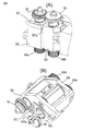
引出しローラ15、16間のローラ・ニップを通過する繊維スライバ18の断面積および/または質量は、図3(A)、図3(B)に示された装置を用いて計測される。
The cross-sectional area and / or mass of the
図3(A)、図3(B)に示された上記装置はまた、引出しローラ7、8間のローラ・ニップを通過する(複数本の繊維スライバから成る)繊維スライバ組合せ物5IVの断面積および/または質量を計測するためにも採用され得る。
The above apparatus shown in FIGS. 3 (A) and 3 (B) also shows a cross-sectional area of a fiber sliver combination 5IV (consisting of a plurality of fiber slivers) that passes through the roller nip between the drawing
図2は、たとえばTruetzschler TC 07などのカード機と巻取りプレート35との間において、該巻取りプレート35の上方にカード機用練篠機構36が配置されるという配置構成を示している。カード機用練篠機構36はスリー・オーバー・スリー練篠機構として設計され、すなわちそれは、3個の下側ローラI、II、IIIおよび3個の上側ローラ37、38、39から成る。練篠機構36の取入口にては取入口ファネル40が配置されると共に、上記練篠機構からの出口には出口ファネル41が配置される。出口ファネル41の下流には2個の引出しローラ42、43が在り、これらローラは、湾曲矢印の方向に回転すると共に、出口ファネル41からの引き伸ばし済み繊維スライバ44を引出す。吐出用下側ローラI、引出しローラ42、43および巻取りプレート35は主要モータ45により駆動されると共に、取入れおよび中央下側ローラIIIおよびIIは制御モータ46により駆動される。モータ45および46は、(不図示の)電子的制御/調整デバイスに接続される。引出しローラ42、43間のローラ・ニップを通過する繊維スライバ44の断面積および/または質量は、図3(A)、図3(B)に示された装置に従い、間隔センサ47を用いて決定される。間隔センサ47は、中央コンピュータ・ユニット26(図1参照)に対応し得る(不図示の)電子的制御/調整デバイスに接続される。参照符号Bは動作方向を表している。
FIG. 2 shows an arrangement configuration in which a card
図3(A)、図3(B)は、少なくとも一本の繊維スライバから成る(図1および図2に示された)繊維スライバ組合せ物の断面積および/または質量を、(図1および図2に示された)一対の測定ローラ7、8および/または15、16および/または42、43により、連続的に計測するデバイスを示している。シャフト端部15aおよび16aにそれぞれ属する(不図示の)シャフト15および16は転動要素軸受50および51内に夫々回転可能に取付けられており、これら軸受は夫々軸受ハウジング52および53内に取付けられている。軸受ハウジング52は移動不能であるが、軸受ハウジング53は、移動不能な回転軸受54回りで矢印C、Dの方向に回動移動可能(枢動可能)に配置される。回転軸受54は、移動不能支持部49に固定される。回動移動可能である軸受ハウジング53は、一端が当接部56に着座するというスプリング55により負荷かつ付勢される。この様にして、軸受ハウジング53、および、それと一体的にローラ7および/または16および/または43は、実質的に直線状の経路上で離間移動され得る。誘導式(非接触式)のアナログ間隔センサ57が移動不能な軸受ハウジング52に一体化され、そのセンサ表面57aは軸受ハウジング53の表面53'と対向して配置されている。軸受ハウジング53の表面53'はセンサ表面57aに対面している。動作状態において、間隔センサ57により測定されるたとえば約1mmである可変間隔aがセンサ表面57aと表面53'との間に存在する。この様にして、各ローラの一方例えばローラ15は移動不能であり、且つ、他方のローラ例えばローラ16は、実質的に直線状の経路上で上記ローラから離間移動可能とされるべく配置される。軸受ハウジング52および支持部49は、(不図示の)機械フレーム上に移動不能に取付けられる。図3(B)に従う開き状態(非動作時)において、間隔bはたとえば約11mmである。参照番号63は開くための押圧クランクを表し、参照番号58は間隔センサ57のリード線を表し、且つ、参照番号48a、48bは(不図示の歯付きベルトにより)上記引出しローラを駆動する2個の歯付きベルト・ホィールを表している。
3 (A) and 3 (B) show the cross-sectional area and / or mass of a fiber sliver combination (shown in FIGS. 1 and 2) consisting of at least one fiber sliver (see FIGS. 1 and 2). A device for continuous measurement is shown by a pair of measuring
図4に依れば誘導式間隔センサ571は、移動不能な軸受ハウジング52の(引出しローラ15に臨む)上側の端部領域における凹所内に一体的に配置される。図5に依れば誘導式間隔センサ572は、移動不能な軸受ハウジング52の(引出しローラ15に臨む)上側の端部領域から所定距離にて、一側に向けて開放された溝内に一体的に配置される。図4および図5に依る配置構成において間隔センサ571および572は移動不能な軸受ハウジング52の一体的構成要素であり、それにより、軸受ハウジング52および該間隔センサ571および572が一体部材として構成されるようになる。
図6に依ると、センサ表面57aに対向して配置された対応表面(検知対象表面)は、回動移動可能である軸受ハウジング53に対して一体化された対応要素59の形態をなしている。
According to FIG. 6, the corresponding surface (detection target surface) arranged opposite to the
図7に依ると、移動不能な軸受ハウジング52の一側に向けて開放された凹所内には、光学式間隔センサ60が移動不能に配置される。間隔センサ60(光センサ)は、光送信器60aおよび光受信器60bから成る。光送信器60aにより発せられた光線61'は、回動移動可能な軸受ハウジング53の円滑表面53'により反射され、反射光線61"は光受信器60bにより受信される。参照番号62は電気リード線を表し、この電気リード線によって間隔センサ60は、評価デバイス(電子的制御/調整デバイス26)と通信する。
According to FIG. 7, the
図1に係る練篠フレーム1はファネル17の下方に引出しローラ15、16を有し、これらローラは、構成に関しては下位アセンブリに取入れられると共に、上記ファネルを通して繊維スライバ18を搬送しもしくは引き出す。上記下位アセンブリは、鋳鉄製基部上に固定して取付けられていて、固定部分および可動部分から成る。引出しローラ15、16の両方が駆動される。開いた引出しローラ、閉じた引出しローラ、および、大径箇所の監視は、非接触誘導式近接スィッチ57を用いて実施される。スライバ検知から帰着する必要な測定値は移動可能な引出しローラの偏位により決定され、上記誘導式アナログ・センサは引出しローラ15、16の間隔aを計測する。上記測定値は、制御システムを用いて評価される。非接触誘導式アナログ・センサに加え、たとえば誘導式または光学式の変位変換器も使用され得る。本発明に依れば、第1に、(たとえばアナログ・センサなどの)測定センサは"全体"の一部として既存の構造要素に対して一体化され、第2に、(ハウジングに対して特有である)基本的に最も変化に富むセンサの一体化は、既存の構造部分もしくは下位アセンブリにおいて達成される。上記センサは、既存の構造的下位アセンブリの外郭形状に合致するハウジング内に収容される。上記センサを上記引出しローラ下位アセンブリに設置もしくは一体化する結果、上記引出しローラ要素の全体的な構造的寸法は不変のままであることから、コンパクトな下位アセンブリ配置構成を形成する結果となる。センサ57は上記引出しローラの固定部分52と併合されることから、上記引出しローラの可動要素53は好適に、一体化された上記センサを減衰する測定タブを提供する。この一体化の結果として、固定要素52は測定主体となり且つ可動要素53は測定の対象物となることから、各引出しローラから成る下位アセンブリ全体がコンパクトな測定システムとなる。
1 has
この一体化は、以下における相当の利点に帰着する:
−簡素で経済的なセンサ設置
−取付け箇所は上記ハウジングの外郭形状により固定されるので、調節もしくは設定が不要であること
−問題のない交換
−空間の節約
−開いた引出しローラ、閉じた引出しローラ、および、大径箇所の監視。
This integration results in considerable advantages in the following:
-Simple and economical sensor installation-The mounting location is fixed by the outer shape of the housing, so there is no need for adjustment or setting-No problem replacement-Space saving-Open drawer roller, closed drawer roller And monitoring of large diameter points.
上記一体化、および、これに関連して測定箇所を引出しローラの支持要素に関連付け付けたことの結果として、簡素な構成が好適に達成される。上記引出しローラの偏位が電気的測定値へと変換されるという事実に依って、制御システム内には測定手段が構成され得る。認識された上記センサの測定値と、上記移動可能な引出しローラの偏位とを使用すれば、幾つかの動作条件を検知することが可能である。繊維スライバの検出に加え、ソフトウェアを使用すれば更に、開いた引出しローラ、閉じた引出しローラの機能、大径箇所、および、スライバ不在を評価することが可能である。測定値が上記ソフトウェアにおいて予め定義されたパラメータ(スライバOK)より小さくまたは大きければ、動作不良が検知されて上記機械は作動停止される。 As a result of the integration and the associated measurement location with the support element of the drawing roller in this connection, a simple configuration is preferably achieved. Due to the fact that the deflection of the drawing roller is converted into an electrical measurement value, a measuring means can be configured in the control system. Several operating conditions can be detected using the recognized measured values of the sensor and the displacement of the movable draw roller. In addition to fiber sliver detection, software can be used to further evaluate open drawer roller, closed drawer roller function, large diameter location, and sliver absence. If the measured value is smaller or larger than a parameter (sliver OK) predefined in the software, a malfunction is detected and the machine is deactivated.
上記一体化形式の測定値計測は、上記取入口ファネルの後における引出しローラにおいても使用され得ることが更に好適である。同一の引出しローラ下位アセンブリ(トング・ローラおよび溝ローラ)もしくは類似物は、同一のソフトウェア評価により測定システムとして使用され得る。 More preferably, the integrated measurement of the measurement value can also be used in the drawing roller after the intake funnel. The same drawer roller subassembly (tongue roller and groove roller) or the like can be used as a measurement system with the same software evaluation.
a 可変間隔
b 間隔
A 動作方向
B 動作方向
C、D 矢印
I 吐出用下側ローラ
II 中央下側ローラ
III 取入れ下側ローラ
1 練篠フレーム
2 練篠機構
3 取入口
4 出口
5 繊維スライバ
5' 繊維スライバ組合せ物
5" 繊維スライバ組合せ物
5"' 引き伸ばされた繊維スライバ
5IV 繊維スライバ組合せ物
6 スライバ案内部材
7、8 引出しローラ
9 間隔センサ/取入口測定要素
10 ウェブ案内部材
11、12、13、14 上側ローラ
15 引出しローラ
15a シャフト端部
16 引出しローラ
16a シャフト端部
17 スライバ・ファネル
18 繊維スライバ/繊維スライバ組合せ物
19 制御モータ
20 主要モータ
21、22 コントローラ
23、24 タコジェネレータ
25 間隔センサ/出口測定要素
26 電子的制御/調整デバイス
27 ディスプレイ・モニタ
28 インタフェース
29 入力デバイス
30 圧力バー
31 メモリ
35 巻取りプレート
36 カード機用練篠機構
37、38、39 上側ローラ
40 取入口ファネル
41 出口ファネル
42、43 引出しローラ
44 引き伸ばし済み繊維スライバ
45 主要モータ
46 制御モータ
47 間隔センサ
48a、48b 歯付きベルト・ホィール
49 移動不能支持部
50、51 転動要素軸受
52 移動不能な軸受ハウジング/固定要素
53 軸受ハウジング/可動要素
53' 円滑表面
54 移動不能な回転軸受
55 スプリング
56 当接部
57 アナログ間隔センサ/非接触誘導式近接スィッチ
571、572 誘導式間隔センサ
57a センサ表面
58 リード線
59 対応要素
60 光学式間隔センサ
60a 光送信器
60b 光受信器
61' 光線
61" 反射光線
62 電気リード線
63 押圧クランク
a Variable interval
b interval
A Movement direction
B Direction of movement
C, D arrows
I Lower roller for discharge
II Center lower roller
III Lower intake roller
1 Nershino frame
2 Nershino Organization
3 Intake
4 Exit
5 Fiber sliver
5 'fiber sliver combination
5 "fiber sliver combination
5 "'stretched fiber sliver
5IV Fiber sliver combination
6 Sliver guide member
7, 8 Drawer roller
9 Spacing sensor / inlet measuring element
10 Web guide members
11, 12, 13, 14 Upper roller
15 Drawer roller
15a Shaft end
16 Drawer roller
16a Shaft end
17 Sliver Funnel
18 Fiber sliver / fiber sliver combination
19 Control motor
20 Major motors
21, 22 Controller
23, 24 Tacho generator
25 Distance sensor / exit measuring element
26 Electronic control / regulation devices
27 Display / Monitor
28 Interface
29 Input devices
30 Pressure bar
31 memory
35 Winding plate
36 Nershino mechanism for card machines
37, 38, 39 Upper roller
40 Inlet funnel
41 Exit funnel
42, 43 Drawer roller
44 Stretched fiber sliver
45 Major motors
46 Control motor
47 Distance sensor
48a, 48b Toothed belt wheel
49 Non-movable support
50, 51 Rolling element bearing
52 Immovable bearing housing / fixing element
53 Bearing housing / moving elements
53 'smooth surface
54 Immovable rotary bearing
55 Spring
56 Abutment
57 Analog distance sensor / Non-contact inductive proximity switch
57 1 and 57 2 inductive distance sensors
57a Sensor surface
58 Lead wire
59 Supported elements
60 Optical distance sensor
60a optical transmitter
60b optical receiver
61 'rays
61 "reflected light
62 Electrical leads
63 Press crank
Claims (75)
上記間隔センサ(9、25;47;57、571、572;60)は、他方のローラ(7、8;15、16;42、43)のための保持要素(52、52b、53a、53b)に結合され、且つ、
上記間隔センサ(9、25;47;57、571、572;60)および上記対応表面(53';59)は、上記各保持要素(52、52b、53a、53b)の側面であって相互に臨むという側面上に夫々配置されることを特徴とする、装置。 Cross-sectional area of at least one fiber sliver for spinning pretreatment machines, in particular card machines, shinoshino frames, combing machines or flyers, which have a drawing mechanism for drawing fiber material in the form of stranded wire And / or a device for continuously measuring the mass, wherein one device is arranged such that one roller is immovable and the other roller is arranged so as to be able to move away from the one roller and to each other. A pair of measuring rollers arranged to be pressed against each other, and the device comprises a corresponding surface coupled to a holding element for one of the rollers (surface to be detected) In a device having a non-contact type distance sensor for measuring a distance from
The distance sensors (9, 25; 47; 57, 57 1 , 57 2 ; 60) are connected to holding elements (52, 52b, 53a, 60) for the other roller (7, 8; 15, 16; 42, 43). 53b) and
The distance sensor (9, 25; 47; 57, 57 1 , 57 2 ; 60) and the corresponding surface (53 ′; 59) are side surfaces of the holding elements (52, 52b, 53a, 53b) A device characterized in that it is arranged on each side facing each other.
連続的に移動する繊維スライバ組合せ物のスライバ質量を測定する少なくともひとつの間隔センサを有する、紡績用前処理機。 A pre-processing machine for spinning, in particular a card machine, a knitting frame or a combing machine, using the device according to any one of claims 1 to 61,
A spinning pre-processing machine having at least one spacing sensor for measuring a sliver mass of a continuously moving fiber sliver combination.
Applications Claiming Priority (2)
| Application Number | Priority Date | Filing Date | Title |
|---|---|---|---|
| DE102008049363.5A DE102008049363B4 (en) | 2008-08-19 | 2008-08-19 | Device for or on a spinning preparation machine, which has a drafting system for drafting strand-like fiber material |
| DE102008049363.5 | 2008-08-19 |
Publications (3)
| Publication Number | Publication Date |
|---|---|
| JP2010047891A true JP2010047891A (en) | 2010-03-04 |
| JP2010047891A5 JP2010047891A5 (en) | 2012-08-16 |
| JP5543145B2 JP5543145B2 (en) | 2014-07-09 |
Family
ID=41171401
Family Applications (1)
| Application Number | Title | Priority Date | Filing Date |
|---|---|---|---|
| JP2009171290A Expired - Fee Related JP5543145B2 (en) | 2008-08-19 | 2009-07-22 | Apparatus for or in a spinning pretreatment machine having a drilling mechanism for drawing fiber material in the form of stranded wire |
Country Status (7)
| Country | Link |
|---|---|
| JP (1) | JP5543145B2 (en) |
| CN (1) | CN101654819B (en) |
| BR (1) | BRPI0902714B8 (en) |
| CH (1) | CH699383B1 (en) |
| DE (1) | DE102008049363B4 (en) |
| GB (1) | GB2462717B (en) |
| IT (1) | IT1397165B1 (en) |
Cited By (1)
| Publication number | Priority date | Publication date | Assignee | Title |
|---|---|---|---|---|
| JP2010047892A (en) * | 2008-08-19 | 2010-03-04 | Truetzschler Gmbh & Co Kg | Device for spinning pre-treating machine having drawing mechanism for drawing fiber material of twisted fiber form or in the pre-treating machine |
Families Citing this family (8)
| Publication number | Priority date | Publication date | Assignee | Title |
|---|---|---|---|---|
| JP5924860B2 (en) * | 2010-12-03 | 2016-05-25 | 株式会社豊田自動織機 | Control method and control device for drafting device in pre-spinning process |
| JP2013253345A (en) * | 2012-06-07 | 2013-12-19 | Toyota Industries Corp | Comber |
| JP5967119B2 (en) * | 2014-03-11 | 2016-08-10 | 株式会社豊田自動織機 | Automatic lap joint |
| DE102015110980A1 (en) | 2015-07-07 | 2017-01-12 | Rieter Ingolstadt Gmbh | Drafting system with several sliver guides |
| DE102017102623A1 (en) * | 2017-02-09 | 2018-08-09 | TRüTZSCHLER GMBH & CO. KG | Process and plant for processing fibers |
| DE102018202665A1 (en) * | 2018-02-22 | 2019-08-22 | Continental Teves Ag & Co. Ohg | Cylinder unit for an electronic braking system of a vehicle |
| DE102018112081A1 (en) * | 2018-05-18 | 2019-11-21 | Rieter Ingolstadt Gmbh | Method for adjusting an axial position of a rotor drive, rotor spinning device, spinning machine and setting gauge and sensor |
| DE112019005076A5 (en) * | 2018-10-12 | 2021-07-01 | TRüTZSCHLER GMBH & CO. KG | Roller mounting |
Citations (5)
| Publication number | Priority date | Publication date | Assignee | Title |
|---|---|---|---|---|
| JPS55112317A (en) * | 1979-02-15 | 1980-08-29 | Toyoda Autom Loom Works Ltd | Uneveness modifier in sliver weight |
| JPH05500572A (en) * | 1990-04-19 | 1993-02-04 | シューベルト、ウント、ザルツェル、マシーネン ファブリーク、アクチェンゲゼルシャフト | measuring device |
| JPH08209467A (en) * | 1994-10-31 | 1996-08-13 | Truetzschler Gmbh & Co Kg | Method for measuring thickness of fiber bundle in controlleddrawing frame |
| JPH1181058A (en) * | 1997-07-01 | 1999-03-26 | Truetzschler Gmbh & Co Kg | Regulation type drafting apparatus for fiber sliver having at least one drafting zone |
| JP2006328626A (en) * | 2005-05-20 | 2006-12-07 | Truetzschler Gmbh & Co Kg | Apparatus for confirming mass and/or mass variation of fiber material such as at least one fiber sliver or fiber web of cotton or synthetic fiber in preprocessing machine for spinning such as flat card, roller card, drawing frame and fine carding machine |
Family Cites Families (8)
| Publication number | Priority date | Publication date | Assignee | Title |
|---|---|---|---|---|
| US4767987A (en) * | 1983-12-12 | 1988-08-30 | Harris Graphics Corporation | Method and apparatus for monitoring film thicknesses by sensing magnetic interaction between members movable to a film thickness distance |
| DE3569760D1 (en) * | 1985-02-15 | 1989-06-01 | Rieter Ag Maschf | Apparatus for the continuous mass control of a fibre ribbon |
| FI852127A0 (en) * | 1985-05-28 | 1985-05-28 | Puumalaisen Tutkimuslaitos Oy | FOERFARANDE FOER MAETNING AV TJOCKLEK AV EN KONTINUERLIG MATERIALBANA OCH ANORDNING FOER TILLAEMPNING AV FOERFARANDET. |
| DD263548A1 (en) * | 1987-08-28 | 1989-01-04 | Textima Veb K | DEVICE FOR CONTINUOUSLY DETERMINING THE MASS OF A FIBRO RIBBON WITH TWO PRESENCE ROLLING ROLLERS |
| DE19710530B4 (en) * | 1997-03-14 | 2007-04-12 | Rieter Ingolstadt Spinnereimaschinenbau Ag | Apparatus for producing or further processing sliver |
| DE29714990U1 (en) * | 1997-08-21 | 1997-10-09 | Louda Guenther Gmbh | Device for measuring the thickness of parts |
| US6278270B1 (en) * | 1999-10-29 | 2001-08-21 | Xerox Corporation | Apparatus and method for detecting small distance changes between opposed surfaces using giant magneto resistance effect sensor |
| DE102005020506A1 (en) * | 2005-04-29 | 2006-11-09 | TRüTZSCHLER GMBH & CO. KG | Device on a drafting system of a spinning machine, in particular track, card, combing machine o. The like., To load the drafting rollers, with at least one pressure cylinder |
-
2008
- 2008-08-19 DE DE102008049363.5A patent/DE102008049363B4/en active Active
-
2009
- 2009-06-24 IT ITMI2009A001116A patent/IT1397165B1/en active
- 2009-07-08 CN CN200910140163.9A patent/CN101654819B/en active Active
- 2009-07-22 JP JP2009171290A patent/JP5543145B2/en not_active Expired - Fee Related
- 2009-08-12 CH CH01262/09A patent/CH699383B1/en unknown
- 2009-08-14 GB GB0914236.5A patent/GB2462717B/en not_active Expired - Fee Related
- 2009-08-18 BR BRPI0902714A patent/BRPI0902714B8/en active IP Right Grant
Patent Citations (5)
| Publication number | Priority date | Publication date | Assignee | Title |
|---|---|---|---|---|
| JPS55112317A (en) * | 1979-02-15 | 1980-08-29 | Toyoda Autom Loom Works Ltd | Uneveness modifier in sliver weight |
| JPH05500572A (en) * | 1990-04-19 | 1993-02-04 | シューベルト、ウント、ザルツェル、マシーネン ファブリーク、アクチェンゲゼルシャフト | measuring device |
| JPH08209467A (en) * | 1994-10-31 | 1996-08-13 | Truetzschler Gmbh & Co Kg | Method for measuring thickness of fiber bundle in controlleddrawing frame |
| JPH1181058A (en) * | 1997-07-01 | 1999-03-26 | Truetzschler Gmbh & Co Kg | Regulation type drafting apparatus for fiber sliver having at least one drafting zone |
| JP2006328626A (en) * | 2005-05-20 | 2006-12-07 | Truetzschler Gmbh & Co Kg | Apparatus for confirming mass and/or mass variation of fiber material such as at least one fiber sliver or fiber web of cotton or synthetic fiber in preprocessing machine for spinning such as flat card, roller card, drawing frame and fine carding machine |
Cited By (1)
| Publication number | Priority date | Publication date | Assignee | Title |
|---|---|---|---|---|
| JP2010047892A (en) * | 2008-08-19 | 2010-03-04 | Truetzschler Gmbh & Co Kg | Device for spinning pre-treating machine having drawing mechanism for drawing fiber material of twisted fiber form or in the pre-treating machine |
Also Published As
| Publication number | Publication date |
|---|---|
| CN101654819B (en) | 2014-10-22 |
| BRPI0902714B8 (en) | 2022-11-08 |
| BRPI0902714A2 (en) | 2010-05-25 |
| BRPI0902714B1 (en) | 2019-08-27 |
| DE102008049363A1 (en) | 2010-02-25 |
| JP5543145B2 (en) | 2014-07-09 |
| GB2462717B (en) | 2012-10-10 |
| ITMI20091116A1 (en) | 2010-02-20 |
| DE102008049363B4 (en) | 2022-10-13 |
| CN101654819A (en) | 2010-02-24 |
| GB0914236D0 (en) | 2009-09-30 |
| IT1397165B1 (en) | 2013-01-04 |
| CH699383B1 (en) | 2013-08-30 |
| GB2462717A (en) | 2010-02-24 |
| CH699383A2 (en) | 2010-02-26 |
Similar Documents
| Publication | Publication Date | Title |
|---|---|---|
| JP2010047891A (en) | Device for spinning pre-treating machine having drawing mechanism for drawing fiber material of twisted fiber form or in the pre-treating machine | |
| JP5221782B2 (en) | For example, in a pre-spinning machine such as a flat card, a roller card, a knitting frame, or a fine cotton machine, the mass of fiber material such as at least one fiber sliver, such as cotton or synthetic fiber, and a fiber web, and / or Or a device to check mass fluctuation | |
| US7765648B2 (en) | Apparatus for detecting a parameter at a plurality of slivers fed to a drafting system of a spinning machine | |
| JP2010047892A (en) | Device for spinning pre-treating machine having drawing mechanism for drawing fiber material of twisted fiber form or in the pre-treating machine | |
| JP2006328626A5 (en) | ||
| EP0354653A2 (en) | Drafting apparatus with autolevelling | |
| US7103440B2 (en) | Use of microwaves for sensors in the spinning industry | |
| GB2326888A (en) | Regulated drawing system for fibre material | |
| JP3545441B2 (en) | Equipment for supplying fiber materials such as lump cotton and synthetic fibers to spinning preparation machines such as cards and dust removing means | |
| JP2000234222A (en) | Controlled draft mechanism | |
| JP3535242B2 (en) | Self-adjusting drafting device for sliver in a drawing machine with inlet measuring member | |
| CN101671873B (en) | Apparatus for on spinning room preparation machine for correcting measurement signal | |
| JPH11172533A (en) | Device for measuring doubling sliver comprising plural slivers in drawframe | |
| JP2011089246A (en) | Apparatus on spinning preparation machine, for example carding machine, draw frame, combing machine or flyer, having a pair of sensing rolls | |
| US20030114951A1 (en) | Device for determining adjustment values for the pre-draft of a sliver | |
| US6223609B1 (en) | Apparatus for measuring the thickness and/or irregularities of a running sliver | |
| GB2369126A (en) | Apparatus at a draw frame for measuring tension during processing of fibre slivers | |
| GB2221699A (en) | Drafting apparatus with autolevelling | |
| CZ297922B6 (en) | Method and apparatus for checking and control of sliver weight |
Legal Events
| Date | Code | Title | Description |
|---|---|---|---|
| A521 | Request for written amendment filed |
Free format text: JAPANESE INTERMEDIATE CODE: A523 Effective date: 20120704 |
|
| A621 | Written request for application examination |
Free format text: JAPANESE INTERMEDIATE CODE: A621 Effective date: 20120704 |
|
| A977 | Report on retrieval |
Free format text: JAPANESE INTERMEDIATE CODE: A971007 Effective date: 20130719 |
|
| A131 | Notification of reasons for refusal |
Free format text: JAPANESE INTERMEDIATE CODE: A132 Effective date: 20130723 |
|
| A521 | Request for written amendment filed |
Free format text: JAPANESE INTERMEDIATE CODE: A523 Effective date: 20130812 |
|
| A131 | Notification of reasons for refusal |
Free format text: JAPANESE INTERMEDIATE CODE: A131 Effective date: 20140218 |
|
| A521 | Request for written amendment filed |
Free format text: JAPANESE INTERMEDIATE CODE: A523 Effective date: 20140313 |
|
| TRDD | Decision of grant or rejection written | ||
| A01 | Written decision to grant a patent or to grant a registration (utility model) |
Free format text: JAPANESE INTERMEDIATE CODE: A01 Effective date: 20140408 |
|
| A61 | First payment of annual fees (during grant procedure) |
Free format text: JAPANESE INTERMEDIATE CODE: A61 Effective date: 20140508 |
|
| R150 | Certificate of patent or registration of utility model |
Ref document number: 5543145 Country of ref document: JP Free format text: JAPANESE INTERMEDIATE CODE: R150 |
|
| LAPS | Cancellation because of no payment of annual fees |