JP2010046947A - Liquid storage body, attaching/detaching structure of liquid storage body, and liquid jetting apparatus - Google Patents
Liquid storage body, attaching/detaching structure of liquid storage body, and liquid jetting apparatus Download PDFInfo
- Publication number
- JP2010046947A JP2010046947A JP2008214195A JP2008214195A JP2010046947A JP 2010046947 A JP2010046947 A JP 2010046947A JP 2008214195 A JP2008214195 A JP 2008214195A JP 2008214195 A JP2008214195 A JP 2008214195A JP 2010046947 A JP2010046947 A JP 2010046947A
- Authority
- JP
- Japan
- Prior art keywords
- liquid
- flow path
- liquid container
- pressing
- cartridge
- Prior art date
- Legal status (The legal status is an assumption and is not a legal conclusion. Google has not performed a legal analysis and makes no representation as to the accuracy of the status listed.)
- Withdrawn
Links
Images


Classifications
-
- B—PERFORMING OPERATIONS; TRANSPORTING
- B41—PRINTING; LINING MACHINES; TYPEWRITERS; STAMPS
- B41J—TYPEWRITERS; SELECTIVE PRINTING MECHANISMS, i.e. MECHANISMS PRINTING OTHERWISE THAN FROM A FORME; CORRECTION OF TYPOGRAPHICAL ERRORS
- B41J2/00—Typewriters or selective printing mechanisms characterised by the printing or marking process for which they are designed
- B41J2/005—Typewriters or selective printing mechanisms characterised by the printing or marking process for which they are designed characterised by bringing liquid or particles selectively into contact with a printing material
- B41J2/01—Ink jet
- B41J2/17—Ink jet characterised by ink handling
- B41J2/175—Ink supply systems ; Circuit parts therefor
- B41J2/17503—Ink cartridges
- B41J2/17513—Inner structure
-
- B—PERFORMING OPERATIONS; TRANSPORTING
- B41—PRINTING; LINING MACHINES; TYPEWRITERS; STAMPS
- B41J—TYPEWRITERS; SELECTIVE PRINTING MECHANISMS, i.e. MECHANISMS PRINTING OTHERWISE THAN FROM A FORME; CORRECTION OF TYPOGRAPHICAL ERRORS
- B41J2/00—Typewriters or selective printing mechanisms characterised by the printing or marking process for which they are designed
- B41J2/005—Typewriters or selective printing mechanisms characterised by the printing or marking process for which they are designed characterised by bringing liquid or particles selectively into contact with a printing material
- B41J2/01—Ink jet
- B41J2/17—Ink jet characterised by ink handling
- B41J2/175—Ink supply systems ; Circuit parts therefor
- B41J2/17503—Ink cartridges
- B41J2/1752—Mounting within the printer
- B41J2/17523—Ink connection
-
- B—PERFORMING OPERATIONS; TRANSPORTING
- B41—PRINTING; LINING MACHINES; TYPEWRITERS; STAMPS
- B41J—TYPEWRITERS; SELECTIVE PRINTING MECHANISMS, i.e. MECHANISMS PRINTING OTHERWISE THAN FROM A FORME; CORRECTION OF TYPOGRAPHICAL ERRORS
- B41J2/00—Typewriters or selective printing mechanisms characterised by the printing or marking process for which they are designed
- B41J2/005—Typewriters or selective printing mechanisms characterised by the printing or marking process for which they are designed characterised by bringing liquid or particles selectively into contact with a printing material
- B41J2/01—Ink jet
- B41J2/17—Ink jet characterised by ink handling
- B41J2/175—Ink supply systems ; Circuit parts therefor
- B41J2/17503—Ink cartridges
- B41J2/17553—Outer structure
Abstract
Description
本発明は、例えばインクカートリッジ等の液体収容体、該液体収容体の着脱構造、及び同着脱構造を備えたインクジェット式記録装置等の液体噴射装置に関する。 The present invention relates to a liquid container such as an ink cartridge, a detachable structure of the liquid container, and a liquid ejecting apparatus such as an ink jet recording apparatus provided with the detachable structure.
従来、液体噴射ヘッドからターゲットに対して液体を噴射する液体噴射装置の一種としてインクジェット式記録装置(以下、「プリンタ」という)が広く知られている。こうしたプリンタのうち、インクを収容したインクカートリッジからインク流路を介して液体噴射ヘッドにインクを供給するタイプのプリンタには、インクカートリッジを着脱可能とするカートリッジホルダが設けられている。そして、カートリッジホルダは、インクカートリッジのインク導出口に対してインク供給針を挿入することで、インクカートリッジ内に貯留されたインクを導出させて液体噴射ヘッドに連通したインク流路内に導入するようになっている。 2. Description of the Related Art Conventionally, an ink jet recording apparatus (hereinafter referred to as “printer”) is widely known as a type of liquid ejecting apparatus that ejects liquid from a liquid ejecting head to a target. Among such printers, a type of printer that supplies ink from an ink cartridge containing ink to a liquid ejecting head via an ink flow path is provided with a cartridge holder that allows the ink cartridge to be attached and detached. Then, the cartridge holder inserts an ink supply needle into the ink outlet port of the ink cartridge so that the ink stored in the ink cartridge is led out and introduced into the ink flow path communicating with the liquid ejecting head. It has become.
ところで、カートリッジホルダは、例えば、インクカートリッジが長期間に亘って取り外された状態にある場合、インク供給針内のインクが大気中に蒸発して体積が減少することで、その体積の減少分だけインク供給針の開口部におけるインク面が降下して凹状のインク面を形成することがある。そして、この状態で、インクカートリッジをカートリッジホルダに装着した場合、インク供給針における開口部の凹状のインク面に存在する空気がそのまま閉じ込められて、気泡としてインク流路内に混入する虞があった。 By the way, for example, when the ink cartridge has been removed for a long period of time, the ink in the ink supply needle evaporates into the atmosphere and the volume is reduced. The ink surface at the opening of the ink supply needle may drop to form a concave ink surface. In this state, when the ink cartridge is mounted on the cartridge holder, the air present on the concave ink surface of the opening of the ink supply needle may be trapped as it is and mixed into the ink flow path as bubbles. .
そこで、特許文献1に記載のプリンタでは、インク流路の一部の壁部を弾性部材により形成すると共に、インクカートリッジの筐体に対して片持ち梁状に支持された弾性片に突起を設けている。そして、インクカートリッジを装着する場合、インクカートリッジ側の突起が弾性部材に対して圧接することで、弾性部材をインク流路の内部に向けて変形させ、弾性部材の変形によってインク供給流路内のインク圧力が高められることで、インク供給針における開口部のインク面が凸状となるようにしていた。
ところで、特許文献1に記載のインクジェット記録装置において、インクカートリッジ側の突起を支持する弾性片は、装着時に突起が弾性部材に対する押圧量を増大させることに伴って、弾性部材から押し返されるように反力を受けて弾性部材から離間する方向に撓み変形するように構成されている。そして、その撓み変形状態は、インクカートリッジの装着が完了した時点では、弾性片が元の形状に復元することで解消するように構成されている。 By the way, in the ink jet recording apparatus described in Patent Document 1, the elastic piece supporting the protrusion on the ink cartridge side is pushed back from the elastic member as the protrusion increases the amount of pressing against the elastic member at the time of mounting. It is configured to bend and deform in a direction away from the elastic member in response to the reaction force. Then, the bending deformation state is configured to be eliminated by restoring the elastic piece to the original shape when the mounting of the ink cartridge is completed.
そのため、この構成では、インクカートリッジの装着完了状態において、弾性部材が弾性片から突出した突起によりインク流路内の容積が減少する方向にある程度押圧された状態となる。したがって、インクカートリッジの取り外し時には、弾性部材が突起による押圧された状態を解消されて復元することで、インク流路の容積が増大することに伴ってインク流路内のインク圧力が低下し、インク流路内に気泡が混入する可能性が依然として残っていた。 Therefore, in this configuration, when the ink cartridge is completely installed, the elastic member is pressed to some extent in the direction in which the volume in the ink flow path is reduced by the protrusion protruding from the elastic piece. Therefore, when the ink cartridge is removed, the state where the elastic member is pressed by the protrusion is canceled and restored, so that the ink pressure in the ink flow path decreases as the volume of the ink flow path increases, and the ink There was still a possibility that air bubbles would enter the flow path.
本発明は、このような事情に鑑みてなされたものであり、その目的は、液体収容体の装着時及び取り外し時において、液体収容体が液体を導出可能に接続される液体流路内に気泡が混入することを回避することができる液体収容体、該液体収容体の着脱構造、及び同着脱構造を備えた液体噴射装置を提供することにある。 The present invention has been made in view of such circumstances, and an object of the present invention is to provide a bubble in a liquid channel to which the liquid container is connected so that the liquid can be led out when the liquid container is mounted and removed. An object of the present invention is to provide a liquid container capable of avoiding contamination, a detachable structure of the liquid container, and a liquid ejecting apparatus including the detachable structure.
上記目的を達成するために、本発明の液体収容体の着脱構造は、内部に液体を収容した液体収容体を着脱可能とし、該液体収容体が装着された場合には、該液体収容体に設けられた液体導出口に対して先端部に開口部を有する液体導出部材が前記液体の導出を可能とするように挿通されると共に、該液体導出部材の前記開口部を介して前記液体収容体の内部から導出された前記液体が前記液体導出部材に連通した液体流路内に流入するようにした液体収容体の着脱構造であって、前記液体流路における少なくとも一部の壁面を該液体流路内の容積が増減する方向への変位自在に構成する流路形成部と、該流路形成部を前記液体流路内の容積が増大する方向に付勢する第1の付勢機構と、該第1の付勢機構の付勢力に抗して前記液体収容体の装着時に前記流路形成部を前記液体流路内の容積が減少する方向に押圧する押圧部材と、該押圧部材を押圧方向に付勢する第2の付勢機構とを備え、該第2の付勢機構の付勢力は、前記液体収容体を装着する場合には、前記第1の付勢機構の付勢力よりも大きくなるように設定されていると共に、前記液体収容体を装着状態から取り外す場合には、前記第1の付勢機構の付勢力よりも小さくなるように設定されている。 In order to achieve the above object, the attachment / detachment structure for a liquid container according to the present invention enables the liquid container containing liquid to be attached and detached, and when the liquid container is attached, the liquid container is attached to the liquid container. A liquid lead-out member having an opening at a tip portion with respect to the provided liquid lead-out port is inserted so as to allow the liquid to be led out, and the liquid container through the opening of the liquid lead-out member A liquid container detachable structure in which the liquid led out from the inside flows into a liquid flow path communicating with the liquid lead-out member, wherein at least a part of the wall surface of the liquid flow path A flow path forming portion configured to be freely displaceable in a direction in which the volume in the path increases or decreases, a first biasing mechanism that biases the flow path forming portion in a direction in which the volume in the liquid flow path increases, The liquid container is mounted against the urging force of the first urging mechanism. A pressing member that sometimes presses the flow path forming portion in a direction in which the volume in the liquid flow path decreases, and a second biasing mechanism that biases the pressing member in the pressing direction. The urging force of the urging mechanism is set to be larger than the urging force of the first urging mechanism when the liquid container is mounted, and the liquid container is removed from the mounted state. Is set to be smaller than the urging force of the first urging mechanism.
上記構成によれば、液体収容体の装着時には、押圧部材を付勢する第2の付勢機構の付勢力は、流路形成部を付勢する第1の付勢機構の付勢力よりも大きくなるように設定されている。そのため、押圧部材は、流路形成部に当接して、該流路形成部を第1の付勢機構の付勢力に抗して液体流路内の容積が減少する方向に押圧することが可能となっている。したがって、液体流路内の容積が減少することに伴って液体流路内の液体の圧力が高められることで、液体流路内と連通する液体導出部材の開口部の液面が凸状となり、液体収容体の液面との間に生じる空気がそのまま閉じ込められた場合に気泡として液体収容体内に混入することを回避することができる。 According to the above configuration, when the liquid container is mounted, the urging force of the second urging mechanism that urges the pressing member is larger than the urging force of the first urging mechanism that urges the flow path forming portion. It is set to be. Therefore, the pressing member can abut against the flow path forming portion and press the flow path forming portion against the urging force of the first urging mechanism in a direction in which the volume in the liquid flow channel decreases. It has become. Therefore, as the volume in the liquid flow path decreases, the liquid pressure in the liquid flow path is increased, so that the liquid level of the opening of the liquid outlet member communicating with the liquid flow path becomes convex, When the air generated between the liquid container and the liquid surface is confined as it is, it can be avoided that the air is mixed as bubbles in the liquid container.
一方、液体収容体の取り外し時には、押圧部材を付勢する第2の付勢機構の付勢力は、流路形成部を付勢する第1の付勢機構の付勢力よりも小さくなるように設定されている。そのため、流路形成部は、第2の付勢機構により付勢された押圧部材が当接しても、その第2の付勢機構の付勢力に抗して液体流路内の容積を増加させることが可能となっている。すなわち、液体収容体が装着状態から取り外されて液体導出部材の開口部が大気に開放される時点では、流路形成部は、液体収容体の装着前の状態まで復元している。そのため、液体収容体の取り外し時点では、液体収容体の装着完了時点よりも液体流路内の容積が増大して液体流路内の液圧は低下しているので、液体流路内に空気が進入することはない。したがって、液体収容体の装着時及び取り外し時において、液体収容体が液体を導出可能に接続される液体流路内に気泡が混入することを回避することができる。 On the other hand, when the liquid container is removed, the biasing force of the second biasing mechanism that biases the pressing member is set to be smaller than the biasing force of the first biasing mechanism that biases the flow path forming portion. Has been. Therefore, even if the pressing member urged by the second urging mechanism abuts, the flow path forming unit increases the volume in the liquid flow channel against the urging force of the second urging mechanism. It is possible. That is, when the liquid container is removed from the mounted state and the opening of the liquid outlet member is opened to the atmosphere, the flow path forming unit is restored to the state before the liquid container is mounted. Therefore, when the liquid container is removed, the volume in the liquid channel increases and the liquid pressure in the liquid channel decreases compared to when the liquid container is completely installed. There is no entry. Therefore, when the liquid container is mounted and removed, it is possible to avoid air bubbles from being mixed into the liquid flow path to which the liquid container is connected so that the liquid can be led out.
また、本発明の液体収容体の着脱構造において、前記第2の付勢機構は、前記押圧部材における押圧方向の基端部を挿入させた状態で該押圧部材を押圧方向に沿う方向への摺動自在に支持すると共に、前記押圧部材が押圧方向に沿って移動することにより容積可変となるように構成された空気室と、該空気室内に設けられ、前記押圧部材の押圧方向の基端部に当接して該押圧部材を押圧方向に付勢する押圧側弾性部材と、前記空気室内を前記押圧部材の移動範囲から外れた位置において外部に連通するように設けられ、前記押圧部材の移動に連動して前記空気室の容積が増減することに伴った同空気室内と外部との間での空気の流動を絞った状態にて可能とする空気絞り流路とにより構成され、前記空気絞り流路は、前記液体収容体を装着する場合には、前記押圧側弾性部材による前記押圧部材に対する付勢力と、前記空気室内の空気による前記押圧部材に対する付勢力との合計が、前記第1の付勢機構による前記流路形成部に対する付勢力よりも大きくなるように、前記空気室内からの空気の流出を規制すると共に、前記液体収容体の装着が完了した場合には、前記押圧側弾性部材による前記押圧部材に対する付勢力と、前記空気室内の空気による前記押圧部材に対する付勢力との合計が、前記第1の付勢機構による前記流路形成部に対する付勢力よりも小さくなるように、前記空気室内からの空気の流出を許容する。 Further, in the attachment / detachment structure of the liquid container according to the present invention, the second urging mechanism slides the pressing member in the direction along the pressing direction in a state where the proximal end portion in the pressing direction of the pressing member is inserted. An air chamber that is movably supported and configured to be variable in volume by moving the pressing member along the pressing direction, and a proximal end portion of the pressing member in the pressing direction provided in the air chamber A pressing-side elastic member that abuts the pressing member in the pressing direction, and communicates with the outside at a position outside the movement range of the pressing member. And an air restricting flow path that enables the air flow between the air chamber and the outside in conjunction with an increase or decrease of the volume of the air chamber in conjunction with the air restricting flow. The path is mounted with the liquid container In this case, the sum of the urging force for the pressing member by the pressing side elastic member and the urging force for the pressing member by the air in the air chamber is applied to the flow path forming portion by the first urging mechanism. The flow of air from the air chamber is restricted so as to be greater than the force, and when the mounting of the liquid container is completed, the biasing force on the pressing member by the pressing side elastic member and the air The outflow of air from the air chamber is allowed so that the sum of the urging force to the pressing member by the indoor air is smaller than the urging force to the flow path forming portion by the first urging mechanism.
上記構成によれば、液体収容体の装着時には、流路形成部は、押圧側弾性部材の付勢力に抗して押圧部材を押し返す。このとき、空気室内の空気は、空気絞り流路から速やかには流出することなく圧縮されて圧力が高められることで、押圧側弾性部材と協働して押圧部材を流路形成部側に付勢する。その結果、第2の付勢機構は、第1の付勢機構の付勢力に抗して流路形成部を液体流路内の容積が減少する方向に押圧することが可能となる。 According to the above configuration, when the liquid container is mounted, the flow path forming unit pushes back the pressing member against the urging force of the pressing side elastic member. At this time, the air in the air chamber is compressed without quickly flowing out from the air restricting flow path and the pressure is increased, so that the pressure member is attached to the flow path forming portion side in cooperation with the pressure side elastic member. Rush. As a result, the second urging mechanism can press the flow path forming portion in the direction in which the volume in the liquid flow path decreases against the urging force of the first urging mechanism.
一方、液体収容体の装着が完了した場合には、空気室内の空気は、空気絞り流路を介して少しずつ流出することで圧力が次第に低下する。そして、第2の付勢機構の付勢力が第1の付勢機構の付勢力を下回った時点で、第1の付勢機構に付勢された流路形成部が第2の付勢機構の付勢力に抗して押圧部材を押し返すことで、液体収容体の装着前の状態に復元することができる。すなわち、液体収容体の着脱に応じて、両付勢機構の付勢力の大小関係を切り替える構成を簡便に実現することが可能となっている。 On the other hand, when the mounting of the liquid container is completed, the pressure gradually decreases as the air in the air chamber gradually flows out through the air throttle channel. When the urging force of the second urging mechanism falls below the urging force of the first urging mechanism, the flow path forming portion urged by the first urging mechanism is By pushing back the pressing member against the urging force, it is possible to restore the state before the liquid container is mounted. That is, it is possible to easily realize a configuration in which the magnitude relationship between the urging forces of the two urging mechanisms is switched according to the attachment / detachment of the liquid container.
また、本発明の液体収容体の着脱構造において、前記第1の付勢機構は、前記流路形成部に前記液体流路内から当接して、前記流路形成部を前記第2の付勢機構の付勢力に抗して、前記押圧部材の押圧方向とは反対方向となる前記液体流路内の容積が増加する方向に付勢する反押圧側弾性部材により構成され、前記反押圧側弾性部材の弾性力は、前記押圧側弾性部材の弾性力よりも大きくなるように設計されている。 Further, in the attachment / detachment structure of the liquid container according to the present invention, the first urging mechanism abuts on the flow path forming portion from within the liquid flow path, and causes the flow path forming portion to move to the second urging force. The anti-pressing-side elastic member is configured by an anti-pressing-side elastic member that urges in the direction in which the volume in the liquid channel increases in the direction opposite to the pressing direction of the pressing member against the urging force of the mechanism. The elastic force of the member is designed to be larger than the elastic force of the pressing side elastic member.
上記構成によれば、液体収容体の装着が完了した場合には、押圧部材により圧縮された空気室内の空気の圧力が外部の圧力と同程度まで低下することで、空気室内の空気による押圧部材に対する付勢力は解消される。その結果、流路形成部は、押圧側弾性部材の付勢力に抗して押圧部材を押圧方向とは反対方向に押し返すことが可能となる。すなわち、液体収容体の装着が完了した場合に、第1の付勢機構の付勢力が第2の付勢機構の付勢力を上回る構成を簡便に実現することができる。 According to the above configuration, when the mounting of the liquid container is completed, the pressure of the air in the air chamber compressed by the pressing member is reduced to the same level as the external pressure. The urging force against is eliminated. As a result, the flow path forming unit can push back the pressing member in the direction opposite to the pressing direction against the urging force of the pressing side elastic member. That is, when the mounting of the liquid container is completed, a configuration in which the urging force of the first urging mechanism exceeds the urging force of the second urging mechanism can be easily realized.
また、本発明の液体収容体の着脱構造において、前記液体収容体に当接して変位する変位部材を更に備え、前記押圧部材は、前記変位部材に設けられ、前記液体収容体の着脱時に前記液体貯留部に対する当接位置と離間位置との間を変位可能に構成されている。 The liquid container attaching / detaching structure according to the present invention further includes a displacement member that contacts and displaces the liquid container, wherein the pressing member is provided on the displacement member, and the liquid container is attached and detached when the liquid container is attached / detached. It is comprised so that a displacement between the contact position with respect to the storage part and a separation position is possible.
上記構成によれば、液体収容体に押圧部材を設けることが不要となるため、液体収容体の設計の自由度を高めることが可能となる。
また、本発明の液体噴射装置は、液体を噴射する液体噴射ヘッドと、上記構成の液体収容体の着脱構造とを備えた。上記構成によれば、上記液体収容体の着脱構造と同様の効果が得られる。
According to the above configuration, it is not necessary to provide a pressing member in the liquid container, and thus the degree of freedom in designing the liquid container can be increased.
The liquid ejecting apparatus of the present invention includes a liquid ejecting head that ejects liquid, and a structure for attaching and detaching the liquid container configured as described above. According to the said structure, the effect similar to the attachment or detachment structure of the said liquid container is acquired.
また、本発明の液体収容体は、先端部に開口部を有する液体導出部材と、該液体導出部材に連通した液体流路における少なくとも一部の壁面を該液体流路内の容積が増減する方向への変位自在に構成する流路形成部と、該流路形成部を前記液体流路内の容積が増大する方向に付勢する第1の付勢機構とを備えた液体収容体ホルダに着脱可能とされ、内部に液体を収容すると共に、前記液体収容体ホルダに装着される場合には前記液体導出部材が前記液体の導出を可能とするように挿通される液体導出口を備えた液体収容体であって、前記液体収容体ホルダに対する装着時に前記第1の付勢機構の付勢力に抗して前記流路形成部を前記液体流路内の容積が減少する方向に押圧する押圧部材と、該押圧部材を押圧方向に付勢する第2の付勢機構とを備え、該第2の付勢機構の付勢力は、前記液体収容体ホルダに装着される場合には、前記第1の付勢機構の付勢力よりも大きくなるように設定されていると共に、前記液体収容体ホルダに対する装着状態から取り外される場合には、前記第1の付勢機構の付勢力よりも小さくなるように設定されている。 Further, the liquid container according to the present invention includes a liquid outlet member having an opening at the tip, and a direction in which the volume in the liquid passage increases or decreases in at least a part of a wall surface of the liquid passage communicating with the liquid outlet member. A liquid container holder having a flow path forming portion configured to be freely displaceable and a first biasing mechanism that biases the flow path forming portion in a direction in which the volume in the liquid flow path increases. A liquid container having a liquid outlet port through which the liquid outlet member is inserted so that the liquid outlet member is allowed to be discharged when the liquid outlet member is mounted in the liquid container holder. A pressing member that presses the flow path forming portion in a direction in which the volume in the liquid flow path decreases against the biasing force of the first biasing mechanism when mounted on the liquid container holder; A second biasing mechanism for biasing the pressing member in the pressing direction; The urging force of the second urging mechanism is set to be larger than the urging force of the first urging mechanism when mounted on the liquid container holder, and When removed from the mounting state with respect to the liquid container holder, it is set to be smaller than the urging force of the first urging mechanism.
上記構成によれば、上記液体収容体の着脱構造及び同着脱構造を備えた液体噴射装置に対して好適に着脱可能な液体収容体を得ることができる。 According to the said structure, the liquid container which can be attached or detached suitably with respect to the liquid ejecting apparatus provided with the attachment / detachment structure of the said liquid container and the said attachment / detachment structure can be obtained.
(第1の実施形態)
以下、本発明を具体化した第1の実施形態を図1〜図10に従って説明する。
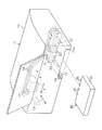
図1に示すように、液体噴射装置としてのインクジェット式記録装置(以下、「プリンタ10」という)は、略箱体状の本体ケース11を備えている。本体ケース11内には、左右一対の側板間に架設されたガイド軸(図示略)に沿ってキャリッジ12が移動可能に設けられている。キャリッジ12は、キャリッジモータ13の駆動力によってガイド軸に沿って主走査方向Xに往復移動するようになっている。
(First embodiment)
Hereinafter, a first embodiment of the present invention will be described with reference to FIGS.
As shown in FIG. 1, an ink jet recording apparatus (hereinafter referred to as “
キャリッジ12の下面側には、液体噴射ヘッドとしての記録ヘッド14が設けられており、記録ヘッド14には液体としてのインクを噴射させる複数の噴射ノズル(図示略)が形成されている。一方、キャリッジ12は、サブタンク(図示略)と、記録ヘッド14に対して圧力調整されたインクを供給するためのバルブユニット(図示略)とを備えており、圧力調整された4色のインク(ブラック、イエロー、マゼンダ、シアン)を記録ヘッド14に供給可能となっている。
A
本体ケース11においてキャリッジ12が移動する空間域よりも下方となる位置には、主走査方向Xと平行をなすように矩形板状のプラテン(図示略)が配置されており、給送された記録用紙はプラテン上を通って主走査方向Xと直交する副走査方向Yに搬送される。そして、記録ヘッド14のノズルからインク滴を吐出しながら主走査方向に移動するキャリッジ12の走査と、副走査方向Yへの記録用紙の所定量の搬送とが交互に行われることにより記録用紙に印刷が施される。
In the
本体ケース11の背面側下部には、カートリッジ収容部(以下、「収容部15」という)が凹設されている。また、本体ケース11内において収容部15の奥側の位置には液体収容体ホルダとしてのカートリッジホルダ(以下、「ホルダ20」という)が配置されている。そして、液体収容体としてのインクカートリッジ(以下、「カートリッジ30」という)は、収容口15aから挿入されてホルダ20に装着される。また、収容部15において収容口15aの一端側には、レバーハンドル28が設けられている。そして、カートリッジ30の装着時には、レバーハンドル28を回動操作してカートリッジ30を収容部15内へ押し込むことで、減速機構(図示略)を介した比較的軽い操作力で、カートリッジ30をホルダ20側の供給針23に差し込むことができる。なお、収容部15に装着されたカートリッジ30は、図示しない係止機構によりその装着位置にロックされるようになっている。
A cartridge housing portion (hereinafter referred to as “
本体ケース11内において、ホルダ20とキャリッジ12との間は4本の可撓性材料からなる供給流路18が集束された帯状の集束流路17によって接続されており、ホルダ20に装着されたカートリッジ30から各供給流路18を通じてキャリッジ12内の各々対応するサブタンク(図示略)に各色のインクが供給されるようになっている。
In the
図1及び図2に示すように、ホルダ20は、カートリッジ30と略同一の横幅(X方向幅)を有する略矩形板状のホルダ本体20aを備えており、該ホルダ本体20aの収容口15aに対向する面がカートリッジ30に連結される連結面20bとなっている。また、ホルダ20の連結面20bには、その長手方向の両端部に配置された一対の位置決め突起21,22と、その間に略等間隔に配置された複数本(本実施形態では4本)の液体導出部材としてのインク供給針(以下、「供給針23」と称す)とが突設されている。また、一方の位置決め突起21の外側近傍には、複数(本実施形態では4つ)の円形状の凹部54(図4参照)が形成されており、各凹部54は流路形成部としてのフィルム部材43により封着されている。
As shown in FIGS. 1 and 2, the
カートリッジ30の収容ケース31の側壁面には、接続端子44aが表面に形成された回路基板44が取着されている。接続端子44aは、回路基板44に実装されたデータの読み書きが可能な半導体記憶装置(図示略)と電気的に接続されている。半導体記憶装置は、収容ケース31に収容される各インクパック38(図3参照)のインクの種類、インク残量、シリアル番号や有効期限等のデータを記憶している。そして、カートリッジ30がホルダ20に装着された状態においては、回路基板の接続端子がホルダ側に設けられた端子部(図示略)に接続されることにより、プリンタ10の制御部(図示略)がカートリッジ30側の半導体記憶装置に対するインク残量等のデータの読み出し及び書き込みが可能となっている。
A
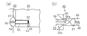
図3に示すように、カートリッジ30の前面(装着面)には、ホルダ20側の一対の位置決め突起21,22と対応する位置に一対の位置決め穴33,34が形成されている。また、カートリッジ30の前面において、ホルダ20側の複数の供給針23とそれぞれ対応する位置には支持口部35がそれぞれ形成されている。そして、カートリッジ30がホルダ20に装着される際は、各位置決め穴33,34に各位置決め突起21,22が嵌入することで、カートリッジ30の装着方向(図1ではY方向)と交差する方向への移動が規制された状態に位置決めされる。続いて、この位置決めされた状態で各支持口部35に各供給針23がそれぞれ差し込まれることで、ホルダ20に連結されるようになっている。
As shown in FIG. 3, a pair of positioning holes 33 and 34 are formed on the front surface (mounting surface) of the
ケース本体31aと蓋部31bよりなる収容ケース31内には、複数のインクパック38が収容されている。インクパック38は、袋部41と、該袋部41の一端部に外側へ突出する状態に固着されたインク導出口形成部材42とを備えている。袋部41は、可撓性の素材から形成されており、ガスバリア性の向上のために、例えば外側をナイロンフィルム、内側をポリエチレンフィルムにより挟み込んだ構成のアルミニウムラミネートフィルムから形成されている。そして、袋部41は、これら2枚の略矩形上のアルミニウムラミネートフィルムを重ね合わせて、それらの周囲を熱溶着等の方法によって接合することにより、インク導出口形成部材42の基部42bに固着された状態に形成され、内部にインクを貯留している。
A plurality of ink packs 38 are housed in the
インク導出口形成部材42は、正面視(支持口部35側からの視方向)で両端側ほど幅が狭くなる船型形状の基部42bと、該基部42bから突出した略円筒形状の供給部42aとが一体形成されており、袋部41のアルミニウムラミネートフィルムは基部42bの側周面に熱圧着されている。インク導出口形成部材42の内部は、液体導出口としてのインク供給口(以下、「供給口42c」という)を形成しており、この供給口42cを介してインクパック38内に収容されたインクが導出される。
The ink
図3及び図4に示すように、インク導出口形成部材42は、ホルダ20側の供給針23が供給口42c内に嵌入することを許容するエラストマにより構成され且つ供給針23の外径と略同一径となる円形状の開口を有する円環状のシール部材45と、該シール部材45と袋部41との間に区画形成された弁室46と、該弁室46内にてシール部材45に着座する供給弁47と、該供給弁47をシール部材45に向けて付勢するコイルバネ48とを備えている。そして、供給口42cは、コイルバネ48に付勢された供給弁47がシール部材45に圧接することにより、常には、シール部材45の開口を介してカートリッジ30外にインクが流出することが規制された閉塞状態となる。一方、ホルダ20側の供給針23が供給口42c内に嵌入したときには、その供給針23に押圧されて供給弁47がコイルバネ48の付勢力に抗して供給口42cの内奥側へ移動してシール部材45から離間することにより、供給口42cは、シール部材45の開口を介してカートリッジ30外にインクが流出することが許容された開放状態となる。
As shown in FIGS. 3 and 4, the ink outlet
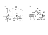
図2〜図4に示すように、カートリッジ30の前面において、ホルダ20側の各フィルム部材43とそれぞれ対応する位置には、略円筒状の凹部49が空気室を形成するように陥入形成されている。そして、各凹部49内には、該凹部49と断面形状が略同一の略円柱状をなす摺動部材50が、ホルダ20側に向けて突出するようにそれぞれ嵌挿されており、各摺動部材50は、凹部49の内周面に沿って摺動することで、凹部49内を封止しつつ容積を増減させるように変位することが可能となっている。そして、カートリッジ30の装着時には、フィルム部材43に対して摺動部材50が押圧力を付与するようになっている。すなわち、摺動部材50は、カートリッジ30の装着時に、フィルム部材43を供給流路18の容積が減少する方向に押圧する押圧部材として機能する。
As shown in FIG. 2 to FIG. 4, a substantially
なお、各凹部49内には、凹部49の内奥面と摺動部材50の基端部との間に介設されるように押圧側弾性部材としてのコイルバネ52が第2の付勢機構を構成するべくそれぞれ収容されている。このコイルバネ52は、摺動部材50の先端部がカートリッジ30の前面よりも常には前方へ突出した状態となるように摺動部材50を押圧方向(フィルム部材43側)に付勢している。
In each
また、カートリッジ30の側壁面には、各凹部49内を外部に連通する複数の空気絞り流路としての連通孔53がそれぞれ貫通形成されている。この連通孔53は、摺動部材50の移動に伴い凹部49内の容積が変動した場合における凹部49内と外部との間での空気の流動を絞った状態で可能とするように、その断面積が微小に形成されている。そのため、摺動部材50が反押圧方向(凹部49内に没入する方向)に移動した場合には、凹部49内から連通孔53を介した外部への空気の流出が絞りをかけられるようにして規制されることになる。そのため、凹部49内では空気が圧縮され、その空気圧がコイルバネ52と協働して摺動部材50を押圧方向(凹部49内から突出する方向)に付勢するようになる。したがって、本実施形態では、こうした連通孔53と、該連通孔53が形成された凹部49、及び該凹部49内に配設されたコイルバネ52により、摺動部材50を押圧方向に付勢する第2の付勢機構が構成されている。
In addition, a plurality of communication holes 53 are formed in the side wall surface of the
一方、ホルダ20の連結面20bにおいて、カートリッジ30の装着方向でカートリッジ30側の各摺動部材50とそれぞれ対向する位置には、各供給針23内に形成された導入流路56(図4参照)と各供給流路18とを個別に接続するようにホルダ20内に形成された複数(本実施形態では4つ)の供給流路57(図4参照)に各々連通する複数(本実施形態では4つ)の凹部54が陥入形成されている。そして、これらの各凹部54の開口を被覆するように、ホルダ20の連結面20bには可撓性材料からなる薄膜状のフィルム部材43がそれぞれ貼着されている。また、各凹部54内には、フィルム部材43に凹部54の内側から当接して凹部54の容積が増大する方向(カートリッジ30側)にフィルム部材43を付勢する反押圧側弾性部材としてのコイルバネ55が第1の付勢機構を構成するべくそれぞれ収容されている。
On the other hand, on the connecting
なお、各供給針23内には、該供給針23の先端部の側面に開口部56aを有する導入流路56がそれぞれ形成されており、各導入流路56は、ホルダ20内に形成された複数の供給流路57にそれぞれ連通している。また、各供給流路57は、供給針23側を基端としてそれぞれ分岐しており、一端側がホルダ20の各凹部54内にそれぞれ接続されると共に、他端側が供給流路18を介して記録ヘッド14内のサブタンクにそれぞれ接続されている。すなわち、本実施形態では、導入流路56、供給流路57、凹部54、及び供給流路18により、カートリッジ30内から導出されたインクを記録ヘッド14に供給する液体流路としてのインク流路58が構成されている。
Each
そこで次に、以上のように構成されたプリンタ10の作用について、特にカートリッジ30の装着時におけるホルダ20の作用に着目して以下説明する。
まず、ホルダ20にカートリッジ30を装着する場合には、本体ケース11における収容部15の収容口15aからカートリッジ30を挿入する。このとき、図5(a)に示すように、カートリッジ30側の摺動部材50とホルダ20側のフィルム部材43との間には、カートリッジ30の装着方向に若干の距離を隔てた構成となっている。また同時に、図5(b)に示すように、カートリッジ30側の供給弁47とホルダ20側の供給針23との間にも同様に距離を隔てた構成となっている。なお、図5(a)(b)は、カートリッジ30が長期間に亘ってホルダ20から取り外された状態を示しており、供給針23は、導入流路56内のインクが開口部56aから大気中に蒸発して体積が減少することで、その体積の減少分だけ供給針23の開口部56aにおけるインク面が降下して凹状のインク面を形成している。
Therefore, the operation of the
First, when the
そして、図6(a)に示すように、摺動部材50とフィルム部材43とが当接する位置を若干過ぎる位置までカートリッジ30を押し込んだ場合には、摺動部材50を押圧方向に付勢するコイルバネ52の弾性力は、フィルム部材43に当接して付勢するコイルバネ55の弾性力よりも小さくなるように設定されているため、摺動部材50は、凹部49の内周面に対して密着して摺動しつつ凹部49の内奥側に押し込まれる。このとき、凹部49内は、摺動部材50により封止された状態で摺動部材50が変位した分だけ容積が減少することで圧力が高まり、摺動部材50をホルダ20側に押圧する付勢力が増大する。その結果、コイルバネ55によるフィルム部材43に対する付勢力は、コイルバネ52による摺動部材50に対する付勢力、及び摺動部材50に封止された凹部49内の空気圧による摺動部材50に対する付勢力の総和と等しくなる。
Then, as shown in FIG. 6A, when the
なお、凹部49の内外を連通する連通孔53は、凹部49内の圧力が上昇した場合に、凹部49内の空気が直ちに外部に漏出することを規制可能な流路抵抗となるように設計されている。一方、フィルム部材43は、コイルバネ55により外方へ付勢されることで、内方へ撓み変形することなくコイルバネ52の付勢力に抗して摺動部材50を押圧する。そのため、フィルム部材43により封止された凹部54内の容積は不変となり、凹部54内に収容されたインク圧は一定となる。したがって、凹部54内と連通する導入流路56内のインク圧も同様に一定となるため、供給針23の開口部56aにおけるインク面は凹状のまま維持される(図6(b)参照)。
The
続いて、図7(a)に示すように、摺動部材50とフィルム部材43とが更に近接する位置までカートリッジ30を押し込んだ場合には、コイルバネ55によるフィルム部材43に対する付勢力と、コイルバネ52及び凹部49内の空気圧による摺動部材50に対する付勢力とが均衡した状態を維持しつつ、摺動部材50がコイルバネ55の付勢力に抗してフィルム部材43を凹部54内の容積が減少する方向に撓み変形させる。すると、凹部54内に収容されたインク圧が上昇すると同時に、凹部54内と連通する導入流路56内のインク圧も同様に上昇する。その結果、図7(b)に示すように、供給針23の開口部56aにおけるインク面は凸状に隆起した形状となる。また同時に、供給針23の先端部は、供給弁47に対して当接する位置に配置される。
Subsequently, as shown in FIG. 7A, when the
そして次に、図8(a)に示すように、カートリッジ30を収容部15内の装着位置に到達するまで更に押し込んだ場合には、コイルバネ55によるフィルム部材43に対する付勢力と、コイルバネ52及び凹部49内の空気圧による摺動部材50に対する付勢力とが均衡した状態を維持しつつ、摺動部材50は、コイルバネ55による付勢力に抗してフィルム部材43を凹部54内の容積が減少する方向に更に撓み変形させる。
Next, as shown in FIG. 8A, when the
また同時に、図8(b)に示すように、供給針23の先端部は、シール部材45の開口を介して弁室46内まで挿入される。そして、袋部41内のインクは、供給針23の先端部に形成された開口部56aを介して導入流路56内に流入し、ホルダ本体20a内の供給流路57、及び該供給流路57に連結された供給流路18内を流動して記録ヘッド14のサブタンクに供給される。なお、弁室46内は、供給針23の外周面にシール部材45の開口の周縁が密着することで密封された状態となる。また、供給弁47は、シール部材45から離間する開弁位置へ移動する場合には、その外周面と弁室46の内周面との間にインク流路となる所定の隙間を有して挿通される。そして、供給弁47が開弁位置に移動した場合には、袋部41内に貯留されているインクは、この隙間を介して弁室46内に流入する。
At the same time, the tip of the
その後、図8(a)に示す状態から、凹部49内の空気が連通孔53を通じて外部に徐々に排出されることで、凹部49内の空気圧が外部の大気圧と等しい値に至るまで降下すると同時に、凹部49内の空気圧による摺動部材50に対する付勢力がほぼ無視できる値に至るまで低下する。このとき、摺動部材50を付勢するコイルバネ52の弾性力は、フィルム部材43を付勢するコイルバネ55の弾性力よりも小さくなるように設定されているため、フィルム部材43は、コイルバネ55に付勢されて凹部54内の容積が増大する方向に(すなわち、外方に)撓み変形することで、コイルバネ52の付勢力に抗して摺動部材50を凹部49の内奥側に更に押し込む。そして、フィルム部材43は、コイルバネ55によるフィルム部材43に対する付勢力とコイルバネ52による摺動部材50に対する付勢力とが均衡した状態になるまでカートリッジ30側に撓み変形した時点で、カートリッジ30をホルダ20に対して装着する前の状態に復元される(図9(a)参照)。
Thereafter, from the state shown in FIG. 8A, when the air in the
また同時に、凹部54内は、容積の増加に伴ってインク圧が降下すると共に、該凹部54内と連通する導入流路56内のインク圧も同様に降下する。このとき、図9(b)に示すように、導入流路56内は、弁室46を介して袋部41内に連通しているため、該導入流路56内のインク圧の降下を相殺するように袋部41からインクが流入する。すなわち、導入流路56、弁室46、及び袋部41は、内部にインクを充填した状態で互いに連通しているため、導入流路56内のインク圧が降下した場合であっても、同導入流路56内には空気が混入することなくインクが供給される。
At the same time, the ink pressure in the
以上、カートリッジ30の装着時におけるホルダ20の作用について説明したが、次に、カートリッジ30の取り外し時におけるホルダ20の作用について以下説明する。
まず、ホルダ20からカートリッジ30を取り外す場合には、図10(a)に示すように、供給針23の先端部が供給口42c内に挿入されることで導入流路56内が開口部56aを介して弁室46内に連通した状態から、カートリッジ30をホルダ20から離間する方向に変位させることで、シール部材45の内縁部をホルダ20側の供給針23の外周面に対して密着させつつ供給針23の先端側に向けて摺動させる。このとき、供給弁47は、コイルバネ48により供給針23側に付勢されているため、供給針23に対する当接状態を維持しつつシール部材45側に変位する。
The operation of the
First, when removing the
そして、シール部材45の内縁部が供給針23の開口部56aを通過する際には、シール部材45の開口の内径と供給針23と外径とが略同一径となるように形成されているため、シール部材45の内縁部が供給針23の外周面に対してインクを払拭するように摺動することで、供給針23の開口部56aには該供給針23の外周面に沿うように平状のインク面が形成される(図10(b)参照)。
When the inner edge of the
さらに、供給針23の先端部がシール部材45の開口から抜脱される際には、供給弁47は、供給針23の先端部に対する当接状態を維持することでシール部材45に近接した位置に配置される。そのため、供給弁47は、供給針23が抜脱された直後に、コイルバネ48に付勢されることでシール部材45に圧接する。したがって、供給針23の抜脱時に、シール部材45の開口を介してカートリッジ30外にインクが流出することを規制することが可能となっている。
Further, when the distal end portion of the
なお、カートリッジ30の取り外し時には、ホルダ20側のフィルム部材43は、カートリッジ30をホルダ20に対して装着する前の状態(すなわち、外方に膨らんだ状態)に復元されている。そのため、カートリッジ30がホルダ20から離間することに伴って、摺動部材50によるフィルム部材43に対する押圧が解消されたとしても、フィルム部材43が変位することはない。したがって、フィルム部材43に封止された凹部54内の容積は不変となり、凹部54内に収容されたインク圧は一定となる。そして、凹部54内と連通する導入流路56内のインク圧も同様に一定となるため、供給針23の開口部56aから導入流路56内に空気が進入することはなく、供給針23の開口部56aにおけるインク面は平状のまま維持される。
When the
本実施形態によれば、以下の効果を得ることができる。
(1)上記実施形態において、カートリッジ30の装着時には、コイルバネ52及び凹部49内の空気圧による摺動部材50に対する付勢力は、コイルバネ55によるフィルム部材43に対する付勢力よりも大きくなるように設定されている。そのため、摺動部材50は、フィルム部材43に当接して、該フィルム部材43をコイルバネ55による付勢力に抗して凹部54内の容積が減少する方向に押圧することが可能となる。したがって、凹部54内の容積が減少することに伴って凹部54内のインク圧が高められることで、凹部54内と連通する供給針23の開口部56aのインク面が凸状となり、カートリッジ30のインク面との間に生じる空気がそのまま閉じ込められることはなく、そうした空気が気泡となってカートリッジ30内に混入することを回避することができる。
According to the present embodiment, the following effects can be obtained.
(1) In the above embodiment, when the
一方、カートリッジ30の取り外し時には、コイルバネ52による摺動部材50に対する付勢力は、コイルバネ55によるフィルム部材43に対する付勢力よりも小さくなるように設定されている。そのため、フィルム部材43は、摺動部材50に当接した状態でコイルバネ52の付勢力に抗して凹部49内の容積を増加させることが可能となる。すなわち、カートリッジ30が取り外されて供給針23の開口部56aが大気に開放される時点では、フィルム部材43は、カートリッジ30の装着前の状態まで復元している。そのため、カートリッジ30の取り外しに伴って摺動部材50によるフィルム部材43の押圧が解消されたとしても、凹部54内の容積が増大して凹部54内のインク圧が低下することにより、供給針23の開口部56aを介して空気が進入することはない。したがって、カートリッジ30を取り外した後に再装着する場合であっても、カートリッジ30内に気泡が混入することを回避することができる。
On the other hand, when the
(2)上記実施形態において、カートリッジ30の装着時には、フィルム部材43は、コイルバネ52の付勢力に抗して摺動部材50を押圧する。このとき、摺動部材50により凹部49内に封入された空気は、連通孔53から流出することなく圧縮されて圧力が高められることで、コイルバネ52と協働して摺動部材50をフィルム部材43側に付勢する。その結果、摺動部材50は、コイルバネ55の付勢力に抗してフィルム部材43を凹部54内の容積が減少する方向に押圧することが可能となる。そして、カートリッジ30の装着が完了した場合には、摺動部材50により凹部49内に封入された空気は、連通孔53を介して外部に少しずつ流出することで圧力が次第に低下する。そして、コイルバネ52及び凹部49内の空気圧による付勢力がコイルバネ55による付勢力を下回った時点で、コイルバネ55に付勢されたフィルム部材43がコイルバネ52及び凹部49内の空気圧の付勢力に抗して摺動部材50を押圧することで、カートリッジ30の装着前の状態に復元することができる。したがって、カートリッジ30の着脱に応じて、フィルム部材43及び摺動部材50に対する付勢力の大小関係を切り替える構成を簡便に実現することができる。
(2) In the above embodiment, when the
(第2の実施形態)
次に、本発明の第2の実施形態を図11及び図12に従って説明する。なお、この第2の実施形態は第1の実施形態との対比において次の点で構成が相違している。すなわち、本実施形態では、フィルム部材43を押圧する摺動部材50が、プリンタ10に着脱されるカートリッジ30に設けられることなく、ホルダ20に対して回動自在に連結された変位部材としてのレバー部材に設けられている点が第1の実施形態と異なっている。したがって、以下の説明においては、第1の実施形態と同一又は相当する部材構成については同一符号を付して重複説明を省略するものとする。
(Second Embodiment)
Next, a second embodiment of the present invention will be described with reference to FIGS. The second embodiment differs from the first embodiment in the following points. That is, in the present embodiment, the sliding
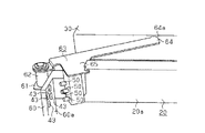
図11に示すように、本実施形態のホルダ20は、略矩形板状のホルダ本体20aを有しており、該ホルダ本体20aの長手方向の一端側には、カートリッジ30の装着方向に沿うように壁部60が立設されている。壁部60は、ホルダ本体20aの長手方向の内側に面した内側壁面60aを有しており、該内側壁面60aには複数(本実施形態では4つ)のフィルム部材43が第1の実施形態の場合と同様に供給流路57に連通する凹部54の開口を塞ぐように配設されている。また、ホルダ本体20aの長手方向の一端側には、該ホルダ本体20aの長手方向の外側に延びる基部61が設けられており、該基部61には、ホルダ本体20aの短手方向に延びる略円柱状の支持ローラ62が回動自在に軸支されている。
As shown in FIG. 11, the
レバー部材63は、その長手方向の一端側が支持ローラ62に回動自在に支持されると共に、その長手方向の他端側には、略扇形状の凸部64が円弧面64aをカートリッジ30側に向けて突設されている。また、レバー部材63には、該レバー部材63の長手方向と直交する方向に延びる延出部65が延設されており、該延出部65において、レバー部材63の回動方向でホルダ本体20aの内側壁面60a上の各フィルム部材43とそれぞれ対向する位置には略円柱状の摺動部材50がそれぞれ突設されている。なお、レバー部材63は、常には、図示しないコイルバネにより、摺動部材50がフィルム部材43から離間する方向に回動するように付勢されている。
The
そこで次に、以上のように構成されたレバー部材63の作用を図12に従って説明する。
まず、本実施形態のホルダ20にカートリッジ30を装着する場合には、図12(a)に示すように、カートリッジ30をレバー部材63の凸部64に対する当接位置までホルダ20側に向けて差し込む。続いて、カートリッジ30を装着方向(図12(a)では左方向)に更に差し込んだ場合には、レバー部材63は、カートリッジ30の前面(装着面)がレバー部材63の凸部64の円弧面64aに当接して該円弧面64a上を摺動すると共に、コイルバネの付勢力に抗して支持ローラ62の軸線を中心とする円弧軌道を描きながら時計回り方向に回動する。そして、摺動部材50は、レバー部材63に連動してフィルム部材43に対する当接位置まで回動した後、フィルム部材43に封止された凹部54内の容積が減少する方向にフィルム部材43を押圧する(図12(b)参照)。また同時に、ホルダ20側の供給針23は、カートリッジ30側のインク導出口形成部材42内に嵌入することで、カートリッジ30内に貯留されたインクを外部に導出することが可能となる。なお、供給針23をインク導出口形成部材42に嵌入する時点で、フィルム部材43は、摺動部材50により所定量だけ押圧されており、該フィルム部材43に封止された凹部54内のインク圧は上昇している。そして、該凹部54内と連通する供給針23の導入流路56内のインク圧も同様に上昇することで、供給針23の開口部56aにおけるインク面は凸状となっている。したがって、カートリッジ30の装着時に、供給針23を介してカートリッジ30内に気泡が混入することを抑制することが可能となっている。
Next, the operation of the
First, when the
そして、図12(b)に示す状態にあるカートリッジ30をホルダ20から取り外した場合には、レバー部材63は、カートリッジ30による押圧が解除されることで、コイルバネの付勢力に従って支持ローラ62の軸線を中心とする円弧軌道を描きながら反時計回り方向に回動する。このとき、フィルム部材43により封止された凹部54内の容積は既にカートリッジ30の装着前の状態(図12(a)参照)に復元されている。そのため、摺動部材50がレバー部材63に連動してフィルム部材43から離間する方向に回動することで、摺動部材50によるフィルム部材43に対する押圧が解消されたとしても、フィルム部材43が凹部54内の容積を増加させる方向に更に変位することはない。
When the
したがって、本実施形態では、上記第1の実施形態の効果(1)(2)に加えて以下に示す効果を得ることができる。
(3)本実施形態では、カートリッジ30に摺動部材50を設けることが不要となるため、カートリッジ30の設計の自由度を高めることが可能となっている。
Therefore, in this embodiment, in addition to the effects (1) and (2) of the first embodiment, the following effects can be obtained.
(3) In this embodiment, since it is not necessary to provide the sliding
なお、上記各実施形態は以下のような別の実施形態に変更してもよい。
・上記各実施形態において、導入流路56内のインク圧を調整可能な圧力調整部を設け、該圧力調整部が、カートリッジ30の着脱に応じて導入流路56内のインク圧を調整する構成としてもよい。
In addition, you may change each said embodiment into another embodiment as follows.
In each of the above embodiments, a pressure adjustment unit that can adjust the ink pressure in the
・上記各実施形態において、フィルム部材43に当接して付勢する付勢部材として、板ばね等の他の形態の付勢部材を用いてもよい。
・上記各実施形態において、摺動部材50に当接して付勢する付勢部材として、板ばね等の他の形態の付勢部材を用いてもよい。
In each of the above embodiments, the urging member of another form such as a leaf spring may be used as the urging member that abuts against the
In each of the above embodiments, the urging member of another form such as a leaf spring may be used as the urging member that abuts against the sliding
・上記各実施形態において、カートリッジ30側の凹部49内の圧力を調整可能な圧力調整部を設け、該圧力調整部が、カートリッジ30の装着時に凹部49内の圧力を減圧するタイミングを制御する構成としてもよい。このとき、圧力調整部が凹部49内を大気圧よりも低い圧力となるように減圧可能な構成である場合には、摺動部材50を押圧するコイルバネ52の弾性力がフィルム部材43を押圧するコイルバネ55の弾性力よりも大きくなるように設定することが可能となる。
In each of the above embodiments, a pressure adjustment unit that can adjust the pressure in the
・上記各実施形態において、カートリッジ30側の凹部49の内外を連通する連通孔53に対して、凹部49内の空気圧が増加した場合に、該凹部49内の空気が急激に外部に排出されることを規制すると共に、該凹部49内の空気が徐々に外部に排出されることを許容する弁機構を設けてもよい。
In each of the above embodiments, when the air pressure in the
・上記各実施形態において、ホルダ20側のフィルム部材43を押圧する押圧部材として、該フィルム部材43に対向するように配置された凹部の開口を封止する可撓性のフィルム部材を採用してもよい。
In each of the above embodiments, as the pressing member that presses the
・上記各実施形態において、インクジェット式のプリンタと、インクカートリッジが採用されているが、インク以外の他の液体を噴射したり吐出したりする液体噴射装置と、その液体を収容した液体収容体を採用しても良い。微小量の液滴を吐出させる液体噴射ヘッド等を備える各種の液体消費装置に流用可能である。なお、液滴とは、上記液体噴射装置から吐出される液体の状態をいい、粒状、涙状、糸状に尾を引くものも含むものとする。また、ここでいう液体とは、液体消費装置が噴射させることができるような材料であれ良い。例えば、物質が液相であるときの状態のものであれば良く、粘性の高い又は低い液状態、ゾル、ゲル水、その他の無機溶剤、有機溶剤、溶液、液状樹脂、液状金属(金属融液)のような流状態、また物質の一状態としての液体のみならず、顔料や金属粒子などの固形物からなる機能材料の粒子が溶媒に溶解、分散または混合されたものなどを含む。また、液体の代表的な例としては上記実施例の形態で説明したようなインク等が挙げられる。ここで、インクとは一般的な水性インクおよび油性インク並びにジェルインク、ホットメルトインク等の各種液体組成物を包含するものとする。液体消費装置の具体例としては、例えば液晶ディスプレイ、EL(エレクトロルミネッセンス)ディスプレイ、面発光ディスプレイ、カラーフィルタの製造などに用いられる電極材や色材などの材料を分散または溶解のかたちで含む液体を噴射する液体噴射装置、バイオチップ製造に用いられる生体有機物を噴射する液体噴射装置、精密ピペットとして用いられ試料となる液体を噴射する液体噴射装置、捺染装置やマイクロディスペンサ等であってもよい。さらに、時計やカメラ等の精密機械にピンポイントで潤滑油を噴射する液体噴射装置、光通信素子等に用いられる微小半球レンズ(光学レンズ)などを形成するために紫外線硬化樹脂等の透明樹脂液を基板上に噴射する液体噴射装置、基板などをエッチングするために酸又はアルカリ等のエッチング液を噴射する液体噴射装置を採用しても良い。そして、これらのうちいずれか一種の噴射装置および液体収容体に本発明を適用することができる。 In each of the above embodiments, an ink jet printer and an ink cartridge are employed. However, a liquid ejecting apparatus that ejects or ejects liquid other than ink, and a liquid container that contains the liquid are provided. It may be adopted. The present invention can be used for various liquid consuming devices including a liquid ejecting head that discharges a minute amount of liquid droplets. In addition, a droplet means the state of the liquid discharged from the said liquid ejecting apparatus, and shall also include what pulls a tail in granular shape, tear shape, and thread shape. Moreover, the liquid here may be a material that can be ejected by the liquid consuming apparatus. For example, it may be in the state when the substance is in a liquid phase, and may be in a liquid state with high or low viscosity, sol, gel water, other inorganic solvents, organic solvents, solutions, liquid resins, liquid metals (metal melts) ) And a liquid as one state of the substance, as well as particles in which functional material particles made of solid materials such as pigments and metal particles are dissolved, dispersed or mixed in a solvent. In addition, as a typical example of the liquid, the ink described in the above embodiment can be used. Here, the ink includes general water-based inks and oil-based inks, and various liquid compositions such as gel inks and hot-melt inks. As a specific example of the liquid consuming device, for example, a liquid containing a material such as an electrode material or a color material used for manufacturing a liquid crystal display, an EL (electroluminescence) display, a surface emitting display, a color filter, or the like in a dispersed or dissolved form. It may be a liquid ejecting apparatus for ejecting, a liquid ejecting apparatus for ejecting a bio-organic material used for biochip manufacturing, a liquid ejecting apparatus for ejecting a liquid as a sample used as a precision pipette, a textile printing apparatus, a microdispenser, or the like. In addition, transparent resin liquids such as UV curable resin to form liquid injection devices that pinpoint lubricant oil onto precision machines such as watches and cameras, and micro hemispherical lenses (optical lenses) used in optical communication elements. A liquid ejecting apparatus that ejects a liquid onto the substrate or a liquid ejecting apparatus that ejects an etching solution such as an acid or an alkali to etch the substrate may be employed. The present invention can be applied to any one of these ejecting apparatuses and liquid containers.
10…液体噴射装置としてのプリンタ、14…液体噴射ヘッドとしての記録ヘッド、20…液体収容体ホルダとしてのホルダ、23…液体導出部材としての供給針、30…液体収容体としてのカートリッジ、42c…液体導出口としての供給口、43…流路形成部としてのフィルム部材、49…空気室としての凹部、50…押圧部材としての摺動部材、52…第2の付勢機構を構成する押圧側弾性部材としてのコイルバネ、53…空気絞り流路としての連通孔、55…第1の付勢機構を構成する反押圧側弾性部材としてのコイルバネ、56a…開口部、58…液体流路としてのインク流路、63…変位部材としてのレバー部材。
DESCRIPTION OF
Claims (6)
前記液体流路における少なくとも一部の壁面を該液体流路内の容積が増減する方向への変位自在に構成する流路形成部と、
該流路形成部を前記液体流路内の容積が増大する方向に付勢する第1の付勢機構と、
該第1の付勢機構の付勢力に抗して前記液体収容体の装着時に前記流路形成部を前記液体流路内の容積が減少する方向に押圧する押圧部材と、
該押圧部材を押圧方向に付勢する第2の付勢機構と
を備え、
該第2の付勢機構の付勢力は、
前記液体収容体を装着する場合には、前記第1の付勢機構の付勢力よりも大きくなるように設定されていると共に、
前記液体収容体を装着状態から取り外す場合には、前記第1の付勢機構の付勢力よりも小さくなるように設定されていることを特徴とする液体収容体の着脱構造。 A liquid lead-out member having an opening at a tip portion with respect to the liquid lead-out port provided in the liquid container when the liquid container containing the liquid is detachable and the liquid container is attached. Is inserted so as to allow the liquid to be led out, and the liquid flow path through which the liquid led out from the inside of the liquid container through the opening of the liquid leading member communicates with the liquid leading member A detachable structure of the liquid container that is allowed to flow into the interior,
A flow path forming portion configured to displace at least a part of the wall surface in the liquid flow path in a direction in which the volume in the liquid flow path increases or decreases;
A first biasing mechanism that biases the flow path forming portion in a direction in which the volume in the liquid flow path increases;
A pressing member that presses the flow path forming portion in a direction in which the volume in the liquid flow path decreases when the liquid container is mounted against the biasing force of the first biasing mechanism;
A second biasing mechanism that biases the pressing member in the pressing direction,
The biasing force of the second biasing mechanism is
When mounting the liquid container, while being set to be greater than the biasing force of the first biasing mechanism,
A structure for attaching and detaching a liquid container, wherein the liquid container is set to be smaller than the urging force of the first urging mechanism when the liquid container is removed from the mounted state.
前記第2の付勢機構は、
前記押圧部材における押圧方向の基端部を挿入させた状態で該押圧部材を押圧方向に沿う方向への摺動自在に支持すると共に、前記押圧部材が押圧方向に沿って移動することにより容積可変となるように構成された空気室と、
該空気室内に設けられ、前記押圧部材の押圧方向の基端部に当接して該押圧部材を押圧方向に付勢する押圧側弾性部材と、
前記空気室内を前記押圧部材の移動範囲から外れた位置において外部に連通するように設けられ、前記押圧部材の移動に連動して前記空気室の容積が増減することに伴った同空気室内と外部との間での空気の流動を絞った状態にて可能とする空気絞り流路と
により構成され、
前記空気絞り流路は、
前記液体収容体を装着する場合には、
前記押圧側弾性部材による前記押圧部材に対する付勢力と、前記空気室内の空気による前記押圧部材に対する付勢力との合計が、前記第1の付勢機構による前記流路形成部に対する付勢力よりも大きくなるように、前記空気室内からの空気の流出を規制すると共に、
前記液体収容体の装着が完了した場合には、
前記押圧側弾性部材による前記押圧部材に対する付勢力と、前記空気室内の空気による前記押圧部材に対する付勢力との合計が、前記第1の付勢機構による前記流路形成部に対する付勢力よりも小さくなるように、前記空気室内からの空気の流出を許容することを特徴とする液体収容体の着脱構造。 In the attachment or detachment structure of the liquid container according to claim 1,
The second urging mechanism is
While the base end portion of the pressing member in the pressing direction is inserted, the pressing member is slidably supported in the direction along the pressing direction, and the volume is variable by moving the pressing member along the pressing direction. An air chamber configured to be,
A pressing-side elastic member that is provided in the air chamber and abuts against a proximal end portion in the pressing direction of the pressing member to urge the pressing member in the pressing direction;
The air chamber is provided so as to communicate with the outside at a position outside the movement range of the pressing member, and the air chamber and the outside according to the increase or decrease of the volume of the air chamber in conjunction with the movement of the pressing member. And an air restricting flow path that enables air flow between the
The air throttle channel is
When mounting the liquid container,
The sum of the urging force for the pressing member by the pressing side elastic member and the urging force for the pressing member by the air in the air chamber is larger than the urging force for the flow path forming portion by the first urging mechanism. So as to regulate the outflow of air from the air chamber,
When the mounting of the liquid container is completed,
The sum of the urging force on the pressing member by the pressing side elastic member and the urging force on the pressing member by the air in the air chamber is smaller than the urging force on the flow path forming portion by the first urging mechanism. As described above, the structure for attaching and detaching a liquid container, which allows the outflow of air from the air chamber.
前記第1の付勢機構は、
前記流路形成部に前記液体流路内から当接して、前記流路形成部を前記第2の付勢機構の付勢力に抗して前記押圧部材の押圧方向とは反対方向となる前記液体流路内の容積が増加する方向に付勢する反押圧側弾性部材により構成され、
前記反押圧側弾性部材の弾性力は、前記押圧側弾性部材の弾性力よりも大きくなるように設計されていることを特徴とする液体収容体の着脱構造。 In the attachment or detachment structure of the liquid container according to claim 2,
The first biasing mechanism includes:
The liquid in contact with the flow path forming portion from the inside of the liquid flow channel and in a direction opposite to the pressing direction of the pressing member against the biasing force of the second biasing mechanism. It is constituted by a counter-pressing side elastic member that urges in a direction in which the volume in the flow path increases,
A structure for attaching and detaching a liquid container, wherein the elastic force of the anti-pressing side elastic member is designed to be larger than the elastic force of the pressing side elastic member.
前記液体収容体に当接して変位する変位部材を更に備え、
前記押圧部材は、前記変位部材に設けられ、前記液体収容体の着脱時に前記流路形成部に対する当接位置と離間位置との間を変位可能に構成されていることを特徴とする液体収容体の着脱構造。 In the attachment or detachment structure of the liquid container according to any one of claims 1 to 3,
A displacement member that contacts and displaces the liquid container;
The pressure member is provided on the displacement member, and is configured to be displaceable between a contact position and a separation position with respect to the flow path forming portion when the liquid container is attached or detached. Detachable structure.
前記液体収容体ホルダに対する装着時に前記第1の付勢機構の付勢力に抗して前記流路形成部を前記液体流路内の容積が減少する方向に押圧する押圧部材と、
該押圧部材を押圧方向に付勢する第2の付勢機構と
を備え、
該第2の付勢機構の付勢力は、
前記液体収容体ホルダに装着される場合には、前記第1の付勢機構の付勢力よりも大きくなるように設定されていると共に、
前記液体収容体ホルダに対する装着状態から取り外される場合には、前記第1の付勢機構の付勢力よりも小さくなるように設定されていることを特徴とする液体収容体。 A liquid lead-out member having an opening at the tip, and a flow path configuration in which at least a part of the wall surface of the liquid flow path communicating with the liquid lead-out member can be displaced in a direction in which the volume in the liquid flow path increases or decreases And a liquid container holder provided with a first urging mechanism for urging the flow path forming portion in a direction in which the volume in the liquid flow path increases, and accommodates the liquid therein And a liquid container having a liquid outlet through which the liquid outlet member is inserted so that the liquid can be led out when the liquid outlet member is attached to the liquid container holder,
A pressing member that presses the flow path forming portion in a direction in which the volume in the liquid flow path decreases against the biasing force of the first biasing mechanism when mounted on the liquid container holder;
A second biasing mechanism that biases the pressing member in the pressing direction,
The biasing force of the second biasing mechanism is
When mounted on the liquid container holder, it is set to be larger than the urging force of the first urging mechanism,
The liquid container, wherein the liquid container is set to be smaller than the urging force of the first urging mechanism when the liquid container holder is detached from the mounting state.
Priority Applications (3)
| Application Number | Priority Date | Filing Date | Title |
|---|---|---|---|
| JP2008214195A JP2010046947A (en) | 2008-08-22 | 2008-08-22 | Liquid storage body, attaching/detaching structure of liquid storage body, and liquid jetting apparatus |
| CN2009101682666A CN101654017B (en) | 2008-08-22 | 2009-08-20 | Liquid container, liquid container mounting and detaching structure, and liquid ejection apparatus |
| US12/545,631 US20100045755A1 (en) | 2008-08-22 | 2009-08-21 | Liquid container, liquid container mounting and detaching structure, and liquid ejection apparatus |
Applications Claiming Priority (1)
| Application Number | Priority Date | Filing Date | Title |
|---|---|---|---|
| JP2008214195A JP2010046947A (en) | 2008-08-22 | 2008-08-22 | Liquid storage body, attaching/detaching structure of liquid storage body, and liquid jetting apparatus |
Publications (2)
| Publication Number | Publication Date |
|---|---|
| JP2010046947A true JP2010046947A (en) | 2010-03-04 |
| JP2010046947A5 JP2010046947A5 (en) | 2011-09-29 |
Family
ID=41695976
Family Applications (1)
| Application Number | Title | Priority Date | Filing Date |
|---|---|---|---|
| JP2008214195A Withdrawn JP2010046947A (en) | 2008-08-22 | 2008-08-22 | Liquid storage body, attaching/detaching structure of liquid storage body, and liquid jetting apparatus |
Country Status (3)
| Country | Link |
|---|---|
| US (1) | US20100045755A1 (en) |
| JP (1) | JP2010046947A (en) |
| CN (1) | CN101654017B (en) |
Cited By (1)
| Publication number | Priority date | Publication date | Assignee | Title |
|---|---|---|---|---|
| JP2015107566A (en) * | 2013-12-03 | 2015-06-11 | 株式会社リコー | Liquid supply device, droplet discharge device, and image formation device |
Families Citing this family (14)
| Publication number | Priority date | Publication date | Assignee | Title |
|---|---|---|---|---|
| US8567932B2 (en) * | 2010-11-17 | 2013-10-29 | Funai Electric Co., Ltd. | Fluid container having fluid interface for micro-fluid applications |
| JP2012210726A (en) * | 2011-03-30 | 2012-11-01 | Brother Industries Ltd | Ink cartridge |
| JP2013049168A (en) | 2011-08-30 | 2013-03-14 | Brother Industries Ltd | Printing fluid cartridge and recording apparatus |
| JP5930164B2 (en) * | 2011-12-26 | 2016-06-08 | セイコーエプソン株式会社 | Piezoelectric element driving method and liquid ejecting apparatus |
| US8646889B2 (en) * | 2012-01-13 | 2014-02-11 | Seiko Epson Corporation | Cartridge and printing device |
| US8931887B2 (en) * | 2012-01-13 | 2015-01-13 | Seiko Epson Corporation | Liquid consumption apparatus, liquid supply member, and liquid supply system |
| US9180673B2 (en) | 2012-04-30 | 2015-11-10 | Hewlett-Packard Development Company, L.P. | Liquid supply |
| US9162468B2 (en) * | 2012-04-30 | 2015-10-20 | Hewlett-Packard Development Company, L.P. | Liquid supply |
| JP2015174263A (en) * | 2014-03-14 | 2015-10-05 | セイコーエプソン株式会社 | Liquid storage body and injection method |
| JP2018161773A (en) * | 2017-03-24 | 2018-10-18 | セイコーエプソン株式会社 | Liquid supply device, liquid discharge device, and container |
| JP6803288B2 (en) * | 2017-03-31 | 2020-12-23 | 理想科学工業株式会社 | Inkjet recording device |
| FR3071767A1 (en) | 2017-10-04 | 2019-04-05 | Dover Europe Sarl | DEVICE AND METHOD FOR INTRODUCING CARTRIDGE |
| JP2020015513A (en) * | 2018-07-24 | 2020-01-30 | セイコーエプソン株式会社 | Liquid storage body holding unit, liquid supply device and liquid jetting device |
| JP7067375B2 (en) * | 2018-08-31 | 2022-05-16 | ブラザー工業株式会社 | system |
Citations (3)
| Publication number | Priority date | Publication date | Assignee | Title |
|---|---|---|---|---|
| JPH0781076A (en) * | 1993-06-29 | 1995-03-28 | Canon Inc | Ink jet recording apparatus |
| JP2002154217A (en) * | 2000-11-20 | 2002-05-28 | Ricoh Co Ltd | Ink cartridge and ink jet recorder |
| JP2007050666A (en) * | 2005-08-19 | 2007-03-01 | Fujifilm Corp | Inkjet recording system, ink cartridge, and inkjet recorder |
Family Cites Families (4)
| Publication number | Priority date | Publication date | Assignee | Title |
|---|---|---|---|---|
| JP3133906B2 (en) * | 1993-08-19 | 2001-02-13 | キヤノン株式会社 | Ink tank cartridge |
| JP2003334935A (en) * | 2002-03-15 | 2003-11-25 | Sharp Corp | Recorder |
| JP3826062B2 (en) * | 2002-04-10 | 2006-09-27 | キヤノン株式会社 | ink cartridge |
| CN2683375Y (en) * | 2003-10-30 | 2005-03-09 | 嘉兴天马打印机耗材有限公司 | Split cartridge |
-
2008
- 2008-08-22 JP JP2008214195A patent/JP2010046947A/en not_active Withdrawn
-
2009
- 2009-08-20 CN CN2009101682666A patent/CN101654017B/en not_active Expired - Fee Related
- 2009-08-21 US US12/545,631 patent/US20100045755A1/en not_active Abandoned
Patent Citations (3)
| Publication number | Priority date | Publication date | Assignee | Title |
|---|---|---|---|---|
| JPH0781076A (en) * | 1993-06-29 | 1995-03-28 | Canon Inc | Ink jet recording apparatus |
| JP2002154217A (en) * | 2000-11-20 | 2002-05-28 | Ricoh Co Ltd | Ink cartridge and ink jet recorder |
| JP2007050666A (en) * | 2005-08-19 | 2007-03-01 | Fujifilm Corp | Inkjet recording system, ink cartridge, and inkjet recorder |
Cited By (1)
| Publication number | Priority date | Publication date | Assignee | Title |
|---|---|---|---|---|
| JP2015107566A (en) * | 2013-12-03 | 2015-06-11 | 株式会社リコー | Liquid supply device, droplet discharge device, and image formation device |
Also Published As
| Publication number | Publication date |
|---|---|
| US20100045755A1 (en) | 2010-02-25 |
| CN101654017B (en) | 2011-05-11 |
| CN101654017A (en) | 2010-02-24 |
Similar Documents
| Publication | Publication Date | Title |
|---|---|---|
| JP2010046947A (en) | Liquid storage body, attaching/detaching structure of liquid storage body, and liquid jetting apparatus | |
| US10144223B2 (en) | Liquid ejecting apparatus and pressure-regulating device | |
| JP6679900B2 (en) | Liquid ejector, pressure regulator | |
| WO2009116299A1 (en) | Container for fluids, and differential pressure valve | |
| US8167415B2 (en) | Liquid container | |
| US20110228016A1 (en) | Image forming apparatus and atmospheric air opening method | |
| JP2010221491A (en) | Liquid supply apparatus and liquid ejecting apparatus | |
| US20200238719A1 (en) | Cartridge and liquid ejecting system | |
| JP6175739B2 (en) | Liquid ejector | |
| JP2010228148A (en) | Liquid supply device and liquid ejector | |
| US10857802B2 (en) | Liquid container | |
| JP2010228238A (en) | Valve unit, fluid supply device, fluid injection device, and method and device for manufacturing valve unit | |
| JP2010120296A (en) | Liquid jet apparatus | |
| US20190084311A1 (en) | Liquid Supply Unit | |
| JP2010223259A (en) | Differential pressure valve unit | |
| JP5007586B2 (en) | Valve unit and fluid ejection device | |
| CN110774769B (en) | Liquid container holding unit, liquid supply device, and liquid ejecting apparatus | |
| JP2005343123A (en) | Pressure reducing valve, carriage, and liquid injection apparatus | |
| US9346280B2 (en) | Liquid storing container | |
| JP2018008435A (en) | Liquid supply device and liquid injection device | |
| JP2009166472A (en) | Liquid feeding device and liquid jetting apparatus | |
| JP6536267B2 (en) | Liquid supply unit | |
| JP5790804B2 (en) | Fluid ejection device | |
| JP2009012425A (en) | Liquid receiving container | |
| JP2022054675A (en) | Liquid jet device |
Legal Events
| Date | Code | Title | Description |
|---|---|---|---|
| RD03 | Notification of appointment of power of attorney |
Free format text: JAPANESE INTERMEDIATE CODE: A7423 Effective date: 20110713 |
|
| RD04 | Notification of resignation of power of attorney |
Free format text: JAPANESE INTERMEDIATE CODE: A7424 Effective date: 20110713 |
|
| A521 | Written amendment |
Free format text: JAPANESE INTERMEDIATE CODE: A523 Effective date: 20110817 |
|
| A621 | Written request for application examination |
Free format text: JAPANESE INTERMEDIATE CODE: A621 Effective date: 20110817 |
|
| A977 | Report on retrieval |
Free format text: JAPANESE INTERMEDIATE CODE: A971007 Effective date: 20121010 |
|
| A131 | Notification of reasons for refusal |
Free format text: JAPANESE INTERMEDIATE CODE: A131 Effective date: 20121016 |
|
| A761 | Written withdrawal of application |
Free format text: JAPANESE INTERMEDIATE CODE: A761 Effective date: 20121214 |