JP2010046920A - Method of manufacturing skin-coated expanded molded form of polystyrene-based resin and skin-coated expanded molded form of polystyrene-based resin - Google Patents
Method of manufacturing skin-coated expanded molded form of polystyrene-based resin and skin-coated expanded molded form of polystyrene-based resin Download PDFInfo
- Publication number
- JP2010046920A JP2010046920A JP2008213276A JP2008213276A JP2010046920A JP 2010046920 A JP2010046920 A JP 2010046920A JP 2008213276 A JP2008213276 A JP 2008213276A JP 2008213276 A JP2008213276 A JP 2008213276A JP 2010046920 A JP2010046920 A JP 2010046920A
- Authority
- JP
- Japan
- Prior art keywords
- skin
- steam
- molded body
- foamed
- polystyrene
- Prior art date
- Legal status (The legal status is an assumption and is not a legal conclusion. Google has not performed a legal analysis and makes no representation as to the accuracy of the status listed.)
- Granted
Links
Images


Abstract
Description
本発明は、ポリスチレン系樹脂発泡粒子成形体の略全面が表皮で被覆された表皮被覆ポリスチレン系樹脂発泡成形体の製造方法に関し、詳しくは、ブロー成形により形成されたポリスチレン系樹脂中空成形体からなる表皮内にポリスチレン系樹脂発泡粒子を充填し、該発泡粒子を加熱して融着させることによりポリスチレン系樹脂発泡粒子成形体を成形し、かつ表皮と発泡粒子成形体とを融着一体化させる、表皮被覆ポリスチレン系樹脂発泡成形体の製造方法に関する。さらに、本発明は、ブロー成形により形成されたポリスチレン系樹脂中空成形体からなる表皮と、該表皮内に位置するポリスチレン系樹脂発泡粒子成形体とからなり、表皮の厚みが薄くても表皮と発泡粒子成形体とが強固に接着した表皮被覆ポリスチレン系樹脂発泡成形体に関する。 The present invention relates to a method for producing a skin-coated polystyrene-based resin foam molded body in which substantially the entire surface of a polystyrene-based resin expanded particle molded body is covered with a skin, and more specifically, comprises a polystyrene resin hollow molded body formed by blow molding. Filling the surface with polystyrene resin foam particles, forming the polystyrene resin foam particles by heating and fusing the foam particles, and fusing and integrating the skin with the foam particles molding, The present invention relates to a method for producing a skin-coated polystyrene-based resin foam molded article. Furthermore, the present invention comprises an outer skin made of a polystyrene resin hollow molded body formed by blow molding and a polystyrene resin foamed particle molded body located in the outer skin, and the skin and foam are formed even if the thickness of the skin is thin. The present invention relates to a skin-coated polystyrene-based resin foam molded article firmly adhered to a particle molded article.
従来、中空状の表皮とその内部に位置する発泡粒子成形体とからなり、表皮と発泡粒子成形体とが融着一体化している表皮被覆発泡成形体が知られている。このような発泡粒子成形体の略全表面を表皮で被覆した発泡成形体を製造する方法は、例えば、下記特許文献1に示されている様に、ブロー成形用分割金型間に垂下させた樹脂パリソンを該金型で挟み込み樹脂パリソンが軟化状態にある間にブロー成形して中空成形体を形成した後、該中空成形体が相当の熱量を保持している間に、該中空成形体内に発泡粒子を充填し、スチームを吹き込むことにより、該発泡粒子を相互に融着させるとともに表皮とも融着一体化させた後、冷却して、表皮で被覆された発泡成形体を得る方法が知られている。
2. Description of the Related Art Conventionally, there is known a skin-covered foamed molded body comprising a hollow skin and a foamed particle molded body positioned inside the skin, wherein the skin and the foamed particle molded body are fused and integrated. A method for producing a foamed molded body in which substantially the entire surface of such a foamed particle molded body is covered with a skin is, for example, suspended between split molds for blow molding as shown in
また、表皮の厚みが薄い、0.3〜3mmの表皮を有する表皮被覆発泡成形体に関して、ブロー成形法により空調装置の水滴受皿及びその製造方法が特許文献2に開示されている。さらに、前記特許文献1と同様にブロー中空成形体が冷却固化する前に、該中空成形体内に発泡粒子を充填し、スチームを吹き込み、該粒子を加熱して相互に融着させ発泡粒子成形体を形成するとともに表皮と一体化させた後、冷却して、表皮で被覆された発泡成形体を得る方法において、発泡粒子相互の融着性を高めるために、中空成形体内にスチーム供給用のパイプ(ピン)を挿入して一方のパイプからスチームを供給し、他方のパイプから排出を行って発泡粒子間にスチームを流通させて発泡させることが特許文献3に開示されている。
Further, regarding a skin-covered foamed molded article having a thin skin with a skin of 0.3 to 3 mm,
特許文献1の方法において中空成形体の冷却固化前に、発泡粒子を中空成形体内に充填しスチームを吹き込み発泡粒子成形体を形成し表皮で被覆された発泡成形体とすることは、表皮を形成する中空成形体の保有する熱量を利用して発泡粒子成形体と表皮との融着を十分に行わせるようにしようとするものである。
In the method of
しかし、表皮である中空成形体の厚みが薄くなると熱容量が小さくなるために表皮が冷えやすくなり、その熱溶着力は低下する傾向にあり、表皮と発泡粒子成形体とを十分に熱溶着させる熱容量を得るためには、3.5mm以上の表皮厚みが必要とされている。表皮の肉厚が薄い場合、すなわち表皮の肉厚が3.5mm未満の場合、発泡粒子成形体と表皮との接着強度が、肉厚が3.5mm以上の表皮を有するものと比較して著しく低くなる傾向にあった。表皮と発泡粒子成形体との接着力が十分でないと、表皮被覆発泡成形体に大きな変形が与えられた場合、表皮と発泡粒子成形体との界面で容易に剥離し、両者が強固に接着しているときに比べて、曲げ強度や曲げ剛性が大きく低下してしまう。 However, when the thickness of the hollow molded body, which is the skin, is reduced, the heat capacity becomes smaller, so the skin is likely to cool, and its thermal welding power tends to decrease, and the heat capacity to sufficiently heat weld the skin and the foamed particle molded body. In order to obtain the thickness, a skin thickness of 3.5 mm or more is required. When the thickness of the epidermis is thin, that is, when the epidermal thickness is less than 3.5 mm, the adhesive strength between the foamed particle molded body and the epidermis is significantly higher than that having an epidermis with a thickness of 3.5 mm or more. Tended to be lower. If the adhesive strength between the skin and the foamed particle molded body is not sufficient, if the skin-covered foamed molded body is subjected to a large deformation, it will easily peel off at the interface between the skin and the foamed particle molded body, and both will adhere firmly. Bending strength and bending rigidity are greatly reduced as compared with the case of the above.
表皮が厚肉の表皮被覆発泡成形体では、発泡粒子成形体と表皮との接着性が良好な高強度製品は得られているが、表皮の肉厚が厚い成形体は製品全体が重くなる。軽量性を考慮して表皮を薄くすると、上記のように、発泡粒子成形体と表皮との接着強度が著しく低下し、接着強度が十分に高く、製品強度も高い表皮で被覆された発泡成形体は得られていないのが実情であり、軽量性と、発泡粒子成形体と表皮との間の接着強度との両立という点で課題を残すものであった。 In the case of a skin-coated foamed molded article having a thick skin, a high-strength product having good adhesion between the foamed particle molded article and the skin is obtained, but a molded article having a thick skin is heavy. When the skin is made thin in consideration of lightness, as described above, the adhesive strength between the foamed particle molded body and the skin is remarkably lowered, and the foam molded body covered with the skin having sufficiently high adhesive strength and high product strength. The actual situation is not obtained, and there remains a problem in terms of both lightness and adhesive strength between the foamed particle molded body and the skin.
一方、特許文献2には、発泡粒子相互及び発泡粒子と表皮とが融着した成形体が得られる旨の記載がある。しかしながら、特許文献2にその成形条件等は特に開示されておらず、従来の一般的なブロー成形法による表皮で被覆された発泡成形体を製造する方法と変わらないものと解される。従来と同様の成形条件で成形検証を行ったが、やはり表皮の厚みが薄い場合には、表皮の熱量が不足して発泡粒子成形体と表皮との間で十分な接着力が得られない。ここで、表皮と発泡粒子成形体との融着力を高めようと、単にスチームの温度を高くすると、発泡粒子成形体と表皮との接着力がさらに低下するばかりか、部位によっては発泡粒子相互の融着自体も悪くなってしまう現象が発生した。製品自体が単純な形状であって、曲げ剛性及び曲げ強さがあまり要求されないような用途であれば、仮に発泡粒子間の融着性、表皮と発泡粒子成形体との融着性が不充分な場合であってもある程度は許容し得るが、曲げ剛性や曲げ強さが要求される用途、例えば風呂蓋のような用途においては、発泡粒子相互の融着性、発泡粒子成形体と表皮との融着性の向上が望まれている。
On the other hand,
さらに、特許文献3に記載の方法について、表皮と発泡粒子成形体間の融着性を向上できないか、検証を行ったところ、表皮の肉厚が薄い場合には、表皮と発泡粒子成形体との接着力が弱い表皮被覆発泡成形体しか得られなかった。さらに、表皮の肉厚が薄くかつ成形品の厚さが相対的に薄い製品の場合には、接着力の低下が顕著であった。
Furthermore, the method described in
本発明は、ブロー成形法により成形された中空成形体内に発泡粒子を充填し、発泡粒子相互を融着させて発泡粒子成形体とし、さらに中空成形体からなる表皮の内面と発泡粒子成形体とが融着一体化した、表皮で被覆された発泡粒子成形体(以下、これを「表皮被覆発泡成形体」と呼称することがある)において、従来表皮の厚みが薄い表皮被覆発泡成形体においては十分に達成されていなかった、表皮と発泡粒子成形体間の接着性の課題を解決した表皮被覆ポリスチレン系樹脂発泡成形体の製造方法を提供することを目的とする。さらに、本発明は、従来得られていなかった、表皮の厚みが薄い表皮被覆発泡成形体において、特に製品成型体自体の厚さも相対的に薄い表皮被覆発泡成形体においても、表皮と発泡粒子成形体とが強固に接着し、発泡粒子相互の融着性、ならびに成形体外観に優れた、表皮被覆ポリスチレン系樹脂発泡粒子成形体を提供することを目的とする。 The present invention is to fill a hollow molded body molded by a blow molding method with foamed particles, fuse the foamed particles together to form a foamed particle molded body, and further, an inner surface of the skin composed of the hollow molded body, the foamed particle molded body, In a foam-coated foam molded body in which the thickness of the skin is conventionally thin, the foam-coated molded body covered with the skin, which is integrally fused (hereinafter sometimes referred to as “skin-coated foam molded body”). An object of the present invention is to provide a method for producing a skin-coated polystyrene-based resin foam molded article that has solved the problem of adhesion between the skin and the foamed particle molded article that has not been sufficiently achieved. Further, the present invention provides a skin and foamed particle molding that has not been obtained in the past, and is a skin-coated foamed molded product having a thin skin, particularly a skin-coated foamed molded product having a relatively thin thickness. An object of the present invention is to provide a skin-coated polystyrene-based resin foam particle molded body that adheres firmly to the body and is excellent in the fusion property between foam particles and the appearance of the molded body.
従来のブロー成形による中空成形体内に発泡粒子を充填し、スチームを供給して発泡粒子相互を融着させた表皮被覆発泡成形体の成形において、発泡粒子の加熱条件は、例えば、前記特許文献1、3に見られるように、0.01〜0.12MPa(G)のスチームが供給される。しかし、このようなスチームで加熱した場合、表皮が薄い表皮被覆発泡成形体である場合には、発泡粒子間相互は接着するものの、表皮と発泡粒子成形体間の接着が十分強固なものが得られない。
In molding of a skin-coated foamed molded article in which foamed particles are filled into a hollow molded body by conventional blow molding and steam is supplied to fuse the foamed particles together, the heating conditions for the foamed particles are, for example, the above-mentioned
本発明者らは、ブロー成形により形成された表皮によって被覆された、表皮被覆スチレン系樹脂発泡成形体の製造について、加熱成形条件等について種々検討を重ねた結果、ブロー成形により表皮を形成する際に型締め時の金型温度を特定の温度に制御し、かつポリスチレン系樹脂発泡粒子を成形する際に、従来一般的に実施されている加熱温度範囲を逸脱した高い温度のスチームを供給すると共に、スチーム供給口におけるスチーム温度及び排出口におけるスチーム温度を特定温度に制御して加熱成形することにより、これまで一般に実施されている成形条件では達成できなかった、表皮が薄い表皮被覆発泡成形体においても発泡粒子相互間の融着性に優れるとともに、発泡粒子成形体と表皮との融着性にも優れ、かつ表面性に優れる表皮被覆発泡成形体が得られることを見出した。 The inventors of the present invention have made various studies on the thermoforming conditions for the production of a skin-coated styrenic resin foam molded body covered with a skin formed by blow molding. In addition to controlling the mold temperature at the time of mold clamping to a specific temperature and molding polystyrene resin expanded particles, it supplies steam at a high temperature that deviates from the heating temperature range generally used in the past. By controlling the steam temperature at the steam supply port and the steam temperature at the discharge port to a specific temperature and performing heat molding, in a skin-covered foamed molded product that has not been achieved under conventional molding conditions, In addition to excellent fusion between the foam particles, the skin with excellent fusion between the molded foam particle and the skin and excellent surface properties. It found that covering the foamed molded product is obtained.
本発明は、(1)分割可能な成形用金型間にポリスチレン系樹脂からなるパリソンを垂下し、金型を型締めして該パリソンをブロー成形することにより中空成形体を成形し、次いで、該中空成形体内にポリスチレン系樹脂発泡粒子を充填し、中空成形体内に挿入した複数のスチーム供給排出ピンからスチームを供給、排出することにより該発泡粒子を加熱して発泡粒子相互を融着させポリスチレン系樹脂発泡粒子成形体を成形すると共に、中空成形体内面と発泡粒子成形体とを融着一体化させる、中空成形体からなる表皮で被覆された発泡成形体の製造方法であって、型締め時の金型温度を[中空成形体の基材樹脂のガラス転移温度−30℃]〜[中空成形体の基材樹脂のガラス転移温度+30℃]の温度とし、複数の前記ピンの一方をスチーム供給側とし他方をスチーム排出側とし、スチーム供給側のピンのスチーム供給口におけるスチーム温度T1を[発泡粒子の基材樹脂のガラス転移温度+10℃]〜[発泡粒子の基材樹脂のガラス転移温度+30℃]に、かつスチーム排出側のピンのスチーム排出口におけるスチーム温度T2を[発泡粒子の基材樹脂のガラス転移温度−5℃]以上に制御して加熱することを特徴とする表皮被覆ポリスチレン系樹脂発泡成形体の製造方法。 The present invention is (1) hanging a parison made of polystyrene resin between molds that can be divided, mold the hollow mold by clamping the mold and blow molding the parison, Polystyrene resin foam particles are filled into the hollow molded body, and steam is supplied from and discharged from a plurality of steam supply / discharge pins inserted into the hollow molded body to heat the foamed particles to fuse the foamed particles with each other. A method for producing a foamed molded article covered with a skin made of a hollow molded article, wherein the molded resin foamed molded article is molded and the inner surface of the hollow molded article and the foamed particulate molded article are fused and integrated. The mold temperature at this time is set to a temperature of [glass transition temperature of the base resin of the hollow molded body−30 ° C.] to [glass transition temperature of the base resin of the hollow molded body + 30 ° C.], and one of the plurality of pins is The steam supply side is the steam discharge side, and the steam temperature T1 at the steam supply port of the pin on the steam supply side is the glass transition temperature of the base resin of the foam particles + 10 ° C. to the glass transition of the base resin of the foam particles And a steam temperature T2 at the steam discharge port of the pin on the steam discharge side is controlled to be equal to or higher than [the glass transition temperature of the base resin of the foamed particles −5 ° C.] and heated. A method for producing a polystyrene resin foam molded article.
(2)前記ポリスチレン系樹脂発泡粒子の発泡剤含有量が発泡粒子1m3当たり60〜250gであることを特徴とする上記(1)記載の表皮被覆ポリスチレン系樹脂発泡成形体の製造方法。 (2) the production method of the above (1) skin covered polystyrene type resin foamed molded article, wherein the blowing agent content of the polystyrene resin foamed beads are foamed particles 1 m 3 per 60~250G.
(3)中空成形体内のスチームをスチーム排出側のピンから−0.09〜−0.06MPa(G)で吸引することを特徴とする上記(1)又は(2)記載の表皮被覆ポリスチレン系樹脂発泡成形体の製造方法。 (3) The skin-coated polystyrene resin according to (1) or (2), wherein the steam in the hollow molded body is sucked from a pin on the steam discharge side at −0.09 to −0.06 MPa (G). A method for producing a foam molded article.
(4)前記ポリスチレン系樹脂発泡粒子の嵩密度が15〜40kg/m3であることを特徴とする上記(1)〜(3)のいずれかに記載の表皮被覆ポリスチレン系樹脂発泡成形体の製造方法。 (4) The production of the skin-coated polystyrene-based resin foam molded article according to any one of (1) to (3) above, wherein a bulk density of the polystyrene-based resin foam particles is 15 to 40 kg / m 3. Method.
(5)前記中空成形体からなる表皮の平均厚みが0.5mm以上3.5mm未満であることを特徴とする上記(1)〜(4)のいずれかに記載の表皮被覆ポリスチレン系樹脂発泡成形体の製造方法。 (5) The skin-coated polystyrene-based resin foam molding according to any one of (1) to (4) above, wherein an average thickness of the skin made of the hollow molded body is 0.5 mm or more and less than 3.5 mm Body manufacturing method.
(6)前記発泡成形体の比表面積が0.4〜1.5cm2/cm3であることを特徴とする上記(1)〜(5)のいずれかに記載の表皮被覆ポリスチレン系樹脂発泡成形体の製造方法。 (6) The skin-coated polystyrene-based resin foam molding according to any one of (1) to (5) above, wherein the foamed molded article has a specific surface area of 0.4 to 1.5 cm 2 / cm 3. Body manufacturing method.
(7)前記ピンを中空成形体周縁の対向する両側面から中空成形体内に挿入し、一側面側をスチーム供給側とし他側面側をスチーム排出側とすることを特徴とする上記(6)記載の表皮被覆ポリスチレン系樹脂発泡成形体の製造方法。 (7) The said (6) description characterized by inserting the said pin into a hollow molded object from the both sides | surfaces which a hollow molded object periphery opposes, and making the other side into the steam discharge side. A method for producing a surface-coated polystyrene-based resin foam molded article.
さらに、(8)ポリスチレン系樹脂発泡粒子成形体と、該発泡粒子成形体の略全面を被覆するポリスチレン系樹脂中空成形体からなる表皮とから構成される表皮被覆ポリスチレン系樹脂発泡成形体において、表皮の平均厚みが0.5mm以上3.5mm未満であり、表皮剥離試験における発泡粒子成形体の材料破壊率が30%以上であることを特徴とする表皮被覆ポリスチレン系樹脂発泡成形体。 Further, (8) a skin-coated polystyrene-based resin foam molded article comprising a polystyrene-based resin foam molded article and a skin made of a polystyrene resin hollow molded article covering substantially the entire surface of the foamed particle molded article. A skin-coated polystyrene-based resin foam molded article characterized by having an average thickness of 0.5 mm or more and less than 3.5 mm and a material destruction rate of the foamed particle molded article in the skin peel test of 30% or more.
(9)前記発泡成形体の比表面積が0.4〜1.5cm2/cm3であることを特徴とする上記(8)記載の表皮被覆ポリスチレン系樹脂発泡成形体。
を要旨とする。
(9) The surface-coated polystyrene-based resin foam molded article according to (8) above, wherein the foam molded article has a specific surface area of 0.4 to 1.5 cm 2 / cm 3 .
Is the gist.
本発明の製造方法によると、ブロー成形金型の型締め時の金型温度を表皮基材樹脂の[ガラス転移温度−30℃]〜[ガラス転移温度+30℃]の温度範囲とすることにより、金型内で表皮の温度を可能な限り高い温度に保ち、さらに、発泡粒子の成形時に、通常のポリスチレン系樹脂発泡粒子成形においては考えられないほどの高温のスチームを発泡粒子が充填された中空成形体内に供給し、スチーム供給口におけるスチーム温度T1が発泡粒子基材樹脂の[ガラス転移温度+10℃]〜[ガラス転移温度+30℃]、かつスチーム排出口におけるスチーム温度T2が発泡粒子基材樹脂の[ガラス転移温度−5℃]以上となるように、速やかに高温のスチームを中空成形体内に流通させることにより、表皮まで高温のスチームを到達させて中空成形体内面を溶融状態とし、表皮被覆発泡粒子成形体の表皮の厚みが薄い場合であっても、表皮を形成する中空成形体内面と発泡粒子成形体との間の十分な接着強度を達成すると共に、発泡粒子相互間の融着性も確保した、表皮被覆発泡成形体が得られる。 According to the production method of the present invention, by setting the mold temperature at the time of clamping the blow mold to the temperature range of [glass transition temperature-30 ° C.] to [glass transition temperature + 30 ° C.] of the skin base resin, In the mold, the temperature of the skin is kept as high as possible. Furthermore, when foamed particles are formed, the foam particles are filled with steam at a high temperature that is unthinkable in ordinary polystyrene resin foam particle molding. The steam temperature T1 at the steam supply port is [glass transition temperature + 10 ° C.] to [glass transition temperature + 30 ° C.] of the expanded particle base resin, and the steam temperature T2 at the steam discharge port is the expanded particle base resin. The high temperature steam is made to reach the epidermis by rapidly circulating the high temperature steam in the hollow molded body so that the [glass transition temperature of -5 ° C.] or higher. Even if the inner surface of the hollow molded body is in a molten state and the skin of the skin-coated foamed particle molded body is thin, sufficient adhesion strength between the inner surface of the hollow molded body that forms the skin and the foamed particle molded body is achieved. In addition, a skin-covered foamed molded article that secures the fusion between the foamed particles can be obtained.
また、本発明の表皮被覆ポリスチレン系樹脂発泡成形体は、従来得られていなかった、ポリスチレン系樹脂中空成形体からなる表皮の平均厚みが0.5mm以上3.5mm未満と薄いにもかかわらず、表皮と表皮内部に位置するポリスチレン系樹脂発泡粒子成形体とが強固に接着した表皮被覆発泡成形体であるので、軽量性に優れながらも、曲げ強度や曲げ剛性に優れた発泡成形体となる。特に、上記曲げ物性が低くなりやすい、比表面積が0.4〜1.5cm2/cm3、即ち相対的に肉薄の表皮被覆発泡成形体においても、十分な曲げ強度や曲げ剛性を有する表皮被覆発泡成形体となる。 In addition, the skin-coated polystyrene-based resin foam molded article of the present invention has not been obtained in the past, although the average thickness of the skin made of a polystyrene-based resin hollow molded article is as thin as 0.5 mm or more and less than 3.5 mm, Since it is a skin-covered foamed molded product in which the skin and the polystyrene-based resin foamed particle molded product positioned inside the skin are firmly bonded, the foamed molded product is excellent in bending strength and bending rigidity while being excellent in light weight. In particular, a skin coating that has sufficient bending strength and bending rigidity even in a skin-coated foamed molded article having a specific surface area of 0.4 to 1.5 cm 2 / cm 3 , which tends to be low in bending physical properties, that is, relatively thin. It becomes a foaming molding.
本発明の製造方法は、従来のブロー成形により成形された中空成形体内に発泡粒子を充填し、次いで中空成形体内へスチームを供給して発泡粒子を相互に融着させ表皮と融着一体化させた表皮被覆発泡成形体を製造する際に、ブロー成形により中空成形体を成形する際の型締め時の金型温度を特定の温度に制御するとともに、従来の表皮被覆ポリスチレン系樹脂発泡成形体の成形において適用される温度よりも高い温度のスチームを中空成形体内に供給し、スチーム供給口におけるスチーム温度T1とスチーム排出口におけるスチーム温度T2が特定の温度範囲となるように制御して加熱成形する、表皮被覆発泡成形体を製造する方法である。この本発明の製造方法により、これまで製造が極めて困難で達成できなかった、表皮が薄い表皮被覆発泡粒子成形体においても、発泡粒子相互間の融着性に優れ、かつ発泡粒子成形体と表皮との融着性にも優れた表皮被覆発泡粒子成形体が得られる。 In the production method of the present invention, foamed particles are filled into a hollow molded body formed by conventional blow molding, and then steam is supplied into the hollow molded body so that the foamed particles are fused with each other to be fused and integrated with the skin. When manufacturing a skin-covered foamed molded product, the mold temperature during mold clamping when forming a hollow molded product by blow molding is controlled to a specific temperature, and a conventional skin-coated polystyrene-based resin foamed molded product Steam with a temperature higher than the temperature applied in the molding is supplied into the hollow molded body, and the steam temperature T1 at the steam supply port and the steam temperature T2 at the steam discharge port are controlled to be in a specific temperature range, and the heat molding is performed. This is a method for producing a skin-coated foamed molded article. With the production method of the present invention, even in a skin-coated foamed particle molded body with a thin skin, which has been extremely difficult to produce so far, it has excellent fusion properties between the foamed particles, and the foamed particle molded body and the skin. A skin-coated foamed particle molded article having excellent fusion properties with the above can be obtained.
より具体的には、中空成形体を成形するときの型締め時の金型温度を、[中空成形体の基材樹脂のガラス転移温度−30℃]〜[中空成形体の基材樹脂のガラス転移温度+30℃]の間の温度とし、中空成形体内に挿入した複数のスチーム供給排出ピン(以下、単にスチームピンという)の一方をスチーム供給側とし他方をスチーム排出側として、従来の製造条件よりも高温(高圧)のスチームを供給し、スチームピンのスチーム供給口におけるスチーム温度T1を[発泡粒子の基材樹脂のガラス転移温度+10℃]〜[発泡粒子の基材樹脂のガラス転移温度+30℃]、かつスチームピンのスチーム排出口におけるスチーム温度T2を[発泡粒子の基材樹脂のガラス転移温度−5℃]以上と、従来よりも高い温度に制御して加熱される。なお、本発明においてスチーム供給排出ピンとは、中空成形体内へスチームを供給する、中空成形体内からスチームを排出する、又はその両方に使用されるピンを意味する。 More specifically, the mold temperature at the time of mold clamping when molding the hollow molded body is set to [glass transition temperature of the base resin of the hollow molded body -30 ° C] to [glass of the base resin of the hollow molded body]. Transition temperature + 30 ° C.], one of a plurality of steam supply / discharge pins (hereinafter simply referred to as “steam pins”) inserted into the hollow molded body, and the other as the steam discharge side. Also, high temperature (high pressure) steam is supplied, and the steam temperature T1 at the steam supply port of the steam pin is [glass transition temperature of base resin of foamed particles + 10 ° C.] to [glass transition temperature of base resin of foamed particles + 30 ° C.] In addition, the steam temperature T2 at the steam outlet of the steam pin is controlled to a temperature higher than that of the conventional glass transition temperature −5 ° C. of the base resin of the expanded particles, and is heated. In the present invention, the steam supply / discharge pin means a pin used for supplying steam into the hollow molded body, discharging steam from the hollow molded body, or both.
本発明において、スチームによる加熱は、中空成形体内に挿入された複数のスチームピンの一方を供給側とし他方を排出側として、供給側からスチームを供給して排出側を開放するか排出側から吸引を行うことによって行われる。加熱方法としては、供給側と排出側を固定して一方向からのみ加熱を行う一方加熱法、あるいは一方を供給側とし他方を排出側として一度スチーム加熱を行った後供給側と排出側とを交替してスチーム加熱を行う交互加熱法のどちらも採用することができるが、発泡粒子同士をより強固に融着させるためには、交互加熱法が好ましい。なお、交互加熱法を採用する場合には、表皮と発泡粒子成形体とを融着させるためには一度目の加熱が重要であることから、一度目の加熱時にT1及びT2が上記温度範囲を満足すればよく、二度目以降のスチーム加熱条件は発泡粒子の融着状況に応じて適宜決定すればよい。 In the present invention, heating by steam is performed by supplying steam from the supply side and opening the discharge side or suctioning from the discharge side, with one of the plurality of steam pins inserted into the hollow molded body as the supply side and the other as the discharge side. Is done by doing As a heating method, the supply side and the discharge side are fixed and heating is performed only from one direction. Alternatively, one side is the supply side and the other is the discharge side. Either of the alternating heating methods that alternately perform steam heating can be employed, but the alternate heating method is preferable in order to fuse the expanded particles more firmly. In the case of employing the alternate heating method, the first heating is important for fusing the skin and the foamed particle compact, so that T1 and T2 are within the above temperature range during the first heating. What is necessary is just to be satisfied, and the second and subsequent steam heating conditions may be appropriately determined according to the fusion state of the expanded particles.
通常、高圧のスチームをスチームチャンバーで所望の圧力に減圧調整し、この圧力を調整したスチームをスチームピンを通して中空成形体内へと供給する。スチーム供給開始直後は中空成形体内の圧力が常圧に近いため、高圧(スチームチャンバー内での圧力)のスチームを供給しても、中空成形体内に供給されるときにはスチームの圧力は低下してしまうので、実際に中空成形体内に供給されているスチームの温度は低くなっている。スチーム供給を続けることにより中空成形体内の圧力が上昇し、中空成形体内に高温のスチームを供給することが可能となる。また、特定温度を超えると発泡粒子が二次発泡して中空成形体内の圧力がさらに上昇するので、より高温のスチームを供給することができるようになる。
このとき、スチームを排出しない場合又はスチーム供給量に対して排出量が小さすぎる場合、或いは発泡粒子の二次発泡力が高すぎてスチームが流通する間隙が小さくなりスチームが排出できない又は排出量が小さくなりすぎる場合には、中空成形体内の圧力が速やかに上昇するので高温のスチームを中空成形体内へ供給することができるが、この高温のスチームを中空成形体内全体に流通させることができなくなる。一方、排出量が大きすぎる場合には、中空成形体内の圧力を上昇させることができず、実際に中空成形体内に供給されるスチーム供給温度を高くすることができない。したがって、中空成形体内に高温のスチームを供給し、かつ十分に流通させるためには、スチームの供給量と排出量とのバランスをとることが重要となる。
Usually, high-pressure steam is decompressed and adjusted to a desired pressure in a steam chamber, and the steam whose pressure has been adjusted is supplied into a hollow molded body through a steam pin. Immediately after the start of steam supply, the pressure in the hollow molded body is close to normal pressure, so even if high pressure steam (pressure in the steam chamber) is supplied, the steam pressure drops when supplied into the hollow molded body. Therefore, the temperature of the steam actually supplied into the hollow molded body is low. By continuing the steam supply, the pressure in the hollow molded body increases, and it becomes possible to supply high-temperature steam into the hollow molded body. Further, when the temperature exceeds a specific temperature, the foamed particles undergo secondary foaming and the pressure in the hollow molded body further increases, so that higher temperature steam can be supplied.
At this time, when the steam is not discharged or when the discharge amount is too small with respect to the steam supply amount, or when the secondary foaming force of the foamed particles is too high, the gap through which the steam flows becomes small, and the steam cannot be discharged or the discharge amount is low. When it becomes too small, the pressure in the hollow molded body rises quickly, so that high-temperature steam can be supplied into the hollow molded body, but this high-temperature steam cannot be circulated throughout the hollow molded body. On the other hand, when the discharge amount is too large, the pressure in the hollow molded body cannot be increased, and the steam supply temperature actually supplied into the hollow molded body cannot be increased. Therefore, it is important to balance the supply amount and discharge amount of steam in order to supply and sufficiently distribute high-temperature steam into the hollow molded body.
本発明において、スチームピンのスチーム供給口におけるスチーム温度とは、実際に中空成形体内に供給されているスチームの温度を意味し、スチーム供給中のスチーム供給口におけるスチームの最高到達温度をT1とする。なお、供給側スチームピンが複数である場合、全てのスチームピンの供給口において、スチーム温度T1が上記範囲内である必要がある。 In the present invention, the steam temperature at the steam supply port of the steam pin means the temperature of the steam that is actually supplied into the hollow molded body, and the maximum temperature of the steam at the steam supply port during the steam supply is T1. . When there are a plurality of supply-side steam pins, the steam temperature T1 needs to be within the above range at the supply ports of all the steam pins.
一方、スチームピンのスチーム排出口におけるスチーム温度とは、実際にスチームが中空成形体内から排出されるときのスチームの温度を意味し、スチーム供給中のスチーム排出口におけるスチームの最高到達温度をT2とする。ここで、T2が[発泡粒子基材樹脂のガラス転移温度−5℃]以上であるということは、高温のスチームが中空成形体内の発泡粒子間を速やかに流通していることを意味する。仮に、特定のスチームピンにおいてT2が低いと、そのスチームピンの周囲は表皮と発泡粒子成形体との接着力が低くなる。したがって、排出側スチームピンが複数である場合、全てのスチームピンの排出口において、スチーム温度T2が上記範囲内である必要がある。 On the other hand, the steam temperature at the steam outlet of the steam pin means the temperature of the steam when the steam is actually discharged from the hollow molded body, and the maximum temperature of the steam at the steam outlet during the steam supply is T2. To do. Here, T2 being equal to or higher than [Glass transition temperature of the foamed particle base resin −5 ° C.] means that high-temperature steam is rapidly flowing between the foamed particles in the hollow molded body. If T2 is low in a specific steam pin, the adhesive force between the skin and the foamed particle molded body is low around the steam pin. Therefore, when there are a plurality of discharge-side steam pins, the steam temperature T2 needs to be within the above range at the discharge ports of all the steam pins.
本発明におけるガラス転移温度とは、JIS K7121−1987に基づき、試験片の状態調節として「一定の熱処理を行った後、ガラス転移温度を測定する場合」を採用して測定される中間点ガラス転移温度を意味する。ガラス転移温度を求めるための試験片としては、溶媒溶解法などにより中空成形体用樹脂ペレット或いは発泡粒子から発泡剤や可塑剤などを除去したものを使用する。測定装置としては、ティー・エイ・インスツルメント社製DSCQ1000などを使用することができる。 The glass transition temperature in the present invention is an intermediate glass transition measured by adopting “when measuring the glass transition temperature after performing a certain heat treatment” as a test piece condition adjustment based on JIS K7121-1987. It means temperature. As a test piece for determining the glass transition temperature, a resin pellet obtained by removing a foaming agent, a plasticizer, or the like from resin pellets or foamed particles for a hollow molded body by a solvent dissolution method or the like is used. As a measuring device, DSCQ1000 manufactured by TA Instruments Inc. can be used.
本発明において、中空成形体内へのスチームピンの挿入箇所及び挿入方向は特に限定されるものではないが、中空成形体の内面側全面及び中空成形体内の発泡粒子全体がスチームにより万遍なく加熱されるように、中空成形体の形状に応じて、中空成形体内へと挿入する箇所及び挿入方向を適宜決定する。スチームピンの挿入跡が嫌われる場合にはスチームピンの挿入方向は少ないほど望ましく、スチームピンの挿入は一方向、或いは二方向から行うことが好ましい。 In the present invention, the location and direction of insertion of the steam pin into the hollow molded body are not particularly limited, but the entire inner surface side of the hollow molded body and the entire foamed particles in the hollow molded body are uniformly heated by steam. Thus, according to the shape of a hollow molded object, the location and insertion direction to insert in a hollow molded object are determined suitably. When the insertion trace of the steam pin is disliked, it is preferable that the steam pin is inserted in a smaller direction, and the steam pin is preferably inserted from one direction or two directions.
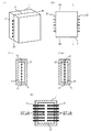
スチームピンの配置の例を説明する模式図を示す。図において、1は金型、11は金型側面、12は成形空間部、2はスチームピンを示し、21は供給側スチームピン、22は排出側スチームピンをそれぞれ示す。金型の一方向からスチームピンを挿入する場合には、図1のように金型の側面からスチームピンを挿入するか、図2または図3のように、分割金型の一方の金型面からスチームピンを挿入することができる。また二方向からスチームピンを挿入する場合には、例えば、図4に示すように金型の両側面から、スチームピン同士を対向させてスチームピンを挿入することができる。また図示しないが、両方の金型面からスチームピン同士を対向させてスチームピンを挿入することもできる。 The schematic diagram explaining the example of arrangement | positioning of a steam pin is shown. In the figure, 1 is a mold, 11 is a mold side surface, 12 is a molding space, 2 is a steam pin, 21 is a supply side steam pin, and 22 is a discharge side steam pin. When inserting the steam pin from one direction of the mold, insert the steam pin from the side of the mold as shown in FIG. 1, or one mold surface of the split mold as shown in FIG. 2 or FIG. A steam pin can be inserted. When inserting the steam pins from two directions, for example, as shown in FIG. 4, the steam pins can be inserted from both side surfaces of the mold with the steam pins facing each other. Although not shown, the steam pins can be inserted with the steam pins facing each other from both mold surfaces.
図1は金型の一方の側面から、スチームピンを挿入した状態を示す例であり、図1では供給側のスチームピン21と排出側のスチームピン22とを交互に配した例を示す。図1(1)は外観斜視図を示し、図1(2)は、正面図を示す。図1(3)は、図1(2)におけるB−B線切断断面図を示し、金型の一方の側面に供給側のスチームピン21と排出側のスチームピン22が交互に配置された状態を示す。図1(4)は、図1(1)におけるA−A線切断断面図(金型のパーティング部での断面)を示す。 FIG. 1 shows an example in which a steam pin is inserted from one side of the mold. FIG. 1 shows an example in which supply-side steam pins 21 and discharge-side steam pins 22 are alternately arranged. FIG. 1 (1) shows an external perspective view, and FIG. 1 (2) shows a front view. FIG. 1 (3) is a cross-sectional view taken along line B-B in FIG. 1 (2), in which supply side steam pins 21 and discharge side steam pins 22 are alternately arranged on one side surface of the mold. Indicates. FIG. 1 (4) shows a cross-sectional view taken along line AA in FIG. 1 (1) (cross section at the parting part of the mold).
図2及び図3は、分割金型の一方の金型面からスチームピンを挿入した状態を示す例である。図2は供給側スチームピン21と排出側スチームピン22とを列毎に交互に配置した例であり、図2(1)は、外観斜視図を示し、図2(2)は、図2(1)におけるA1−A1線切断断面図を示す。図2(3)は、図2(1)におけるB1−B1線切断断面図を示す。スチームピンが挿入された側の金型面(正面)を示す。なお、図示しないが、供給側のスチームピンと排出側のスチームピンとを行毎に交互に配置してもよい。 2 and 3 are examples showing a state where a steam pin is inserted from one mold surface of the split mold. FIG. 2 is an example in which the supply-side steam pins 21 and the discharge-side steam pins 22 are alternately arranged for each column, FIG. 2 (1) shows an external perspective view, and FIG. 2 (2) shows FIG. Sectional view taken along line A1-A1 in 1) is shown. FIG. 2 (3) is a cross-sectional view taken along line B1-B1 in FIG. 2 (1). The mold surface (front surface) on the side where the steam pin is inserted is shown. Although not shown, the supply-side steam pins and the discharge-side steam pins may be alternately arranged for each row.
図3は図2と同様に分割金型の一方の金型面からスチームピンを挿入した状態を示す例で、図3は供給側のスチームピン21と排出側のスチームピン22とを市松模様状に交互に配置した例を示す。図3(1)は外観斜視図を示し、図3(2)は、図3(1)におけるA2−A2線切断断面図を示し、図3(3)は、図3(1)におけるB2−B2切断断面図を示す。 FIG. 3 shows an example in which the steam pins are inserted from one mold surface of the split mold as in FIG. 2, and FIG. 3 shows a checkered pattern of the supply-side steam pins 21 and the discharge-side steam pins 22. Shows an example of alternating arrangement. 3 (1) is an external perspective view, FIG. 3 (2) is a sectional view taken along line A2-A2 in FIG. 3 (1), and FIG. 3 (3) is B2- in FIG. 3 (1). B2 cut sectional drawing is shown.
また二方向からスチームピンを挿入する場合には、一方のスチームピンのうち隣接するスチームピン同士を供給側と排出側とに分けて交互に配置してもよいが、スチームの流通の観点からは図4に示すように相対向する二方向からスチームピンを挿入して、一方側を供給側スチームピンとし、他方を排出側スチームピンとすることがより好ましい。図4は金型の両側面からスチームピンを挿入した状態を示す例であり、図4(1)は外観斜視図を示し、図4(2)は、正面図を示す。図4(3a)は、図4(2)におけるB3−B3線切断断面図を示し、図4(3b)は、図4(2)におけるC−C線切断断面図を示し、図4(4)は、図4(1)におけるA3−A3線切断断面図(金型のパーティング部での断面)を示す。 In addition, when inserting steam pins from two directions, adjacent steam pins of one of the steam pins may be arranged alternately on the supply side and the discharge side, but from the viewpoint of the distribution of steam As shown in FIG. 4, it is more preferable to insert steam pins from two opposite directions, one side being a supply side steam pin and the other side being a discharge side steam pin. FIG. 4 is an example showing a state where steam pins are inserted from both side surfaces of the mold, FIG. 4 (1) shows an external perspective view, and FIG. 4 (2) shows a front view. 4 (3a) shows a sectional view taken along line B3-B3 in FIG. 4 (2), FIG. 4 (3b) shows a sectional view taken along line CC in FIG. 4 (2), and FIG. ) Shows a cross-sectional view taken along line A3-A3 in FIG. 4A (a cross section at the parting part of the mold).
スチームの流通効率の観点から、挿入されるスチームピンの略半数をスチーム供給側とし、残りの略半数をスチーム排出側とすることが好ましい。一方向からスチームピンを挿入する場合には、図1のように供給側と排出側のスチームピンを交互に配置するのが好ましい。特に、金型面から挿入する場合には、図2のように列毎に供給側と排出側を交互に配置することが好ましく、図3のように市松模様状に交互に配置することがさらに好ましい。また二方向からスチームピンを挿入する場合には、一方側のスチームピンのうち隣接するスチームピン同士を供給側と排出側とに分けて交互に配置してもよいが、スチーム流通の観点からは、図4のように相対向する二方向からスチームピンを挿入して一方向側を供給側とし、他方側を排出側とすることがより好ましい。 From the viewpoint of the distribution efficiency of steam, it is preferable that approximately half of the inserted steam pins are the steam supply side and the remaining approximately half are the steam discharge side. When inserting steam pins from one direction, it is preferable to alternately arrange the supply side and discharge side steam pins as shown in FIG. In particular, when inserting from the mold surface, it is preferable to alternately arrange the supply side and the discharge side for each row as shown in FIG. 2, and to arrange alternately in a checkered pattern as shown in FIG. preferable. In addition, when inserting steam pins from two directions, adjacent steam pins among the steam pins on one side may be arranged alternately on the supply side and the discharge side, but from the viewpoint of steam distribution More preferably, the steam pins are inserted from two opposite directions as shown in FIG. 4 so that one direction side is the supply side and the other side is the discharge side.
本発明の方法において、スチーム供給口におけるスチーム温度T1を[発泡粒子の基材樹脂のガラス転移温度+10℃]〜[発泡粒子の基材樹脂のガラス転移温度+30℃]に制御すると共にスチーム排出口におけるスチーム温度T2を[発泡粒子の基材樹脂のガラス転移温度−5℃]以上に制御するためには、従来のポリスチレン系樹脂中空成形体内にポリスチレン系樹脂発泡粒子を充填しスチームを供給して表皮被覆発泡成形体を成形する際に使用される通常のスチームよりも高圧(高温)のスチームが採用される。中空成形体内からのスチームの排出条件にもよるが、T1及びT2を上記範囲内に制御し易いことから、スチームチャンバーにおいて[発泡粒子の基材樹脂のガラス転移温度+22℃]〜[発泡粒子の基材樹脂のガラス転移温度+37℃]の温度範囲に調整したスチームを供給することが好ましい。例えば、ガラス転移温度が105℃であるポリスチレンを基材樹脂とする発泡粒子を用いる場合、スチームチャンバーにおける温度が127℃〜142℃のスチーム、すなわちスチームの圧力は0.15〜0.28MPaとなり、従来の製造方法で使用されているスチームの圧力0.01〜0.12MPaよりも高いスチーム圧となる。 In the method of the present invention, the steam temperature T1 at the steam supply port is controlled to [glass transition temperature of base resin of foamed particles + 10 ° C.] to [glass transition temperature of base resin of foamed particles + 30 ° C.] and steam discharge port In order to control the steam temperature T2 in the above to [Glass transition temperature of the base resin of the foamed particles−5 ° C.] or higher, the polystyrene foamed particles are filled in the conventional polystyrene resin hollow molded body, and steam is supplied. Steam with a higher pressure (higher temperature) than normal steam used when molding the skin-covered foamed molded article is employed. Although it depends on the discharge condition of steam from the hollow molded body, T1 and T2 can be easily controlled within the above range. Therefore, in the steam chamber, [glass transition temperature of base resin of foamed particles + 22 ° C.] to [of foamed particles] It is preferable to supply steam adjusted to a temperature range of the glass transition temperature of the base resin + 37 ° C.]. For example, when using expanded particles whose base resin is polystyrene having a glass transition temperature of 105 ° C., the steam in the steam chamber has a temperature of 127 ° C. to 142 ° C., that is, the steam pressure is 0.15 to 0.28 MPa, The steam pressure is higher than the pressure 0.01 to 0.12 MPa of steam used in the conventional manufacturing method.
通常のポリスチレン系樹脂発泡粒子の型内成形では、高温のスチームを使用すると、発泡粒子成形体の表面が荒れて粗悪になり、製品外観が著しく悪化してしまうので、本発明のような高温のスチームが使用されることはない。それに対して、本発明で製造される表皮被覆発泡成形体は、発泡粒子成形体の略全面が表皮で被覆されているので、発泡粒子成形体の表面荒れが製品表面に直接現れることがないため、高温のスチームにより発泡粒子を成形することができる。 In ordinary in-mold molding of polystyrene resin foam particles, if high temperature steam is used, the surface of the foam particle molded body becomes rough and rough, and the product appearance is remarkably deteriorated. Steam is never used. On the other hand, in the skin-coated foamed molded article produced in the present invention, since the substantially entire surface of the foamed particle molded body is covered with the skin, the surface roughness of the foamed particle molded body does not appear directly on the product surface. The foamed particles can be formed by high-temperature steam.
上記スチーム供給口におけるスチーム温度T1、すなわち中空成形体内に供給される実際のスチーム温度が、[発泡粒子の基材樹脂のガラス転移温度+10℃]未満では、表皮の平均厚みが3.5mm未満であると、表皮と発泡粒子成形体とを強固に融着させることができない。表皮と発泡粒子成形体をより強固に融着させるためには、上記T1は[発泡粒子の基材樹脂のガラス転移温度+12℃]以上であることが好ましく、[発泡粒子の基材樹脂のガラス転移温度+15℃]以上であることがより好ましい。 When the steam temperature T1 at the steam supply port, that is, the actual steam temperature supplied into the hollow molded body is less than [glass transition temperature of base resin of foamed particles + 10 ° C.], the average thickness of the skin is less than 3.5 mm. If so, the skin and the foamed particle molded body cannot be firmly bonded. In order to fuse the outer skin and the foamed particle molded body more firmly, T1 is preferably [glass transition temperature of base resin of foamed particles + 12 ° C.] or higher, and [glass of base resin of foamed particles] Transition temperature + 15 ° C.] or more.
一方、前記T1が[発泡粒子の基材樹脂のガラス転移温度+30℃]を超えるようなスチーム加熱温度では、発泡粒子が収縮、溶融するなどの現象が発生する。また、寸法精度の良好な表皮被覆発泡成形体が得られない。さらに、T1が高すぎると、発泡粒子の二次発泡速度が速くなりすぎて発泡粒子間にスチームが流通する間隙がなくなり、表皮まで高温のスチームを流通させることができないため、表皮と発泡粒子成形体とを強固に接着させることができなくなるばかりか、部位によっては発泡粒子同士の融着も悪くなることがある。かかる観点から、上記T1は、[発泡粒子の基材樹脂のガラス転移温度+28℃]以下であることが好ましく、[発泡粒子の基材樹脂のガラス転移温度+25℃]以下であることがより好ましい。 On the other hand, at a steam heating temperature at which the T1 exceeds [Glass transition temperature of the base resin of the expanded particles + 30 ° C.], phenomena such as contraction and melting of the expanded particles occur. In addition, a skin-coated foamed molded article with good dimensional accuracy cannot be obtained. Furthermore, if T1 is too high, the secondary foaming speed of the foamed particles becomes too high, and there is no space for steam to flow between the foamed particles, so that high-temperature steam cannot be circulated to the skin. In addition to being unable to firmly bond the body, depending on the part, the fusion between the foamed particles may also deteriorate. From this point of view, T1 is preferably [Glass transition temperature of base resin of foamed particles + 28 ° C.] or less, and more preferably [Glass transition temperature of base resin of foamed particles + 25 ° C.] or less. .
本発明において、中空成形体内に複数のスチームピンを挿入して、一方のピンからスチームを供給し、他方のピンから排出を行って発泡粒子間にスチームを流通させて発泡粒子を二次発泡融着させる際に、スチーム排出口におけるスチーム温度T2を[発泡粒子の基材樹脂のガラス転移温度−5℃]以上とする。T1が前記範囲を満足するが、T2が[発泡粒子の基材樹脂のガラス転移温度−5℃]未満であるということは、排出側スチームピンや表皮内面に高温のスチームが流通し難くなっていることを意味する。T2が低すぎると、排出側スチームピン付近に位置する発泡粒子同士の融着性、表皮と発泡粒子成形体との接着力が低下する。かかる観点から、T2を[発泡粒子の基材樹脂のガラス転移温度−2℃]以上に制御して加熱することが好ましく、より好ましくは[発泡粒子の基材樹脂のガラス転移温度]以上である。なお、通常はT2がT1を超えることはない。 In the present invention, a plurality of steam pins are inserted into a hollow molded body, steam is supplied from one pin, discharged from the other pin, and steam is circulated between the expanded particles to expand the expanded particles to secondary expanded fusion. At the time of deposition, the steam temperature T2 at the steam discharge port is set to [glass transition temperature of base resin of foamed particles −5 ° C.] or higher. T1 satisfies the above range, but T2 is less than [Glass transition temperature of base resin of foamed particles−5 ° C.], which means that high-temperature steam is difficult to circulate on the discharge-side steam pins and the inner surface of the skin. Means that If T2 is too low, the fusion between the foamed particles located in the vicinity of the discharge side steam pin and the adhesive force between the skin and the foamed particle molded body are lowered. From this point of view, T2 is preferably controlled to be heated to [glass transition temperature of base resin of foamed particles −2 ° C.] or higher, more preferably [glass transition temperature of base resin of foamed particles] or higher. . Normally, T2 does not exceed T1.
T1を前記範囲としつつ、T2を前記範囲内に制御するためには、上記の高圧スチームを中空成形体内に供給すると共に、下記の手段の中から選択される1以上の方法を採用することが必要である。
[a]スチーム流速を速くすること。
[b]二次発泡能力の低い発泡粒子を使用すること。
T1及びT2を効率よく制御することができ、かつ得られた機械的物性が優れた表皮被覆発泡成形体となることから、[a]と[b]の方法を組み合わせることが好ましい。
In order to control T2 within the above range while keeping T1 within the above range, it is possible to supply the above-described high-pressure steam into the hollow molded body and employ one or more methods selected from the following means: is necessary.
[A] Increase the steam flow rate.
[B] Use expanded particles having a low secondary expansion capability.
It is preferable to combine the methods [a] and [b] because T1 and T2 can be efficiently controlled and the obtained surface-coated foamed molded article has excellent mechanical properties.
上記[a]のスチーム流速を速くするためには、具体的には、真空ポンプなどを使用して中空成形体内を吸引する方法が採用できる。例えば、上記のような高温(高圧)のスチームを供給する場合には、吸引側の吸引圧力を−0.09〜−0.06MPa(G)としてスチームを排出することが好ましい。 In order to increase the steam flow rate of the above [a], specifically, a method of sucking the hollow molded body using a vacuum pump or the like can be employed. For example, when supplying high-temperature (high-pressure) steam as described above, it is preferable to discharge the steam at a suction pressure of −0.09 to −0.06 MPa (G).
さらに、スチームピンの供給口の断面積を小さくする方法が挙げられる。スチームの流速を速くするためには、スチームピン1本あたりの供給口の開口面積が2cm2/本以下であることが好ましい。特に、スチーム供給量およびスチーム流速が調整しやすいため、上記開口面積は0.2〜1.8cm2/本がより好ましく、0.4〜1.4cm2/本が更に好ましい。 Furthermore, the method of making the cross-sectional area of the supply port of a steam pin small is mentioned. In order to increase the flow rate of steam, the opening area of the supply port per steam pin is preferably 2 cm 2 / line or less. In particular, since the supply amount of steam and steam flow rate is easily adjusted, the opening area is more preferably 0.2~1.8cm 2 / present, 0.4~1.4cm 2 / this is more preferable.
スチームピンの挿入方向が一方向である場合には、スチームピンの側面のみに供給口及び/又は排出口を有すれば良いが、スチームピンの挿入方向が相対向する二方向である場合には、側面のみではなくピンの先端にも供給口及び/又は排出口を有することが好ましい。 When the steam pin insertion direction is one direction, it is only necessary to have a supply port and / or a discharge port only on the side surface of the steam pin, but when the steam pin insertion direction is two opposite directions, It is preferable to have a supply port and / or a discharge port not only on the side but also on the tip of the pin.
本発明におけるスチームピンの内径はスチーム供給量、スチーム排出量、スチーム流速が調整しやすいことから、1.5〜6.0mmが好ましく、2.0〜4.0mmがさらに好ましい。一方、スチームピンの外径が小さすぎるとスチームピンの内径が小さくなってスチーム供給量やスチーム排出量が少なくなりやすいため、T1、T2が達成できない虞がある。スチームピンの素材にもよるが、例えばスチームピンが鋼管である場合には、表皮被覆発泡成形体の成形時に必要な強度を確保するためには、スチームピンの肉厚は概ね2mm以上必要とされることから、スチームピンの直径は5.5mm以上であることが好ましく、6mm以上であることがより好ましい。一方、直径が大きすぎると成形体表面にスチームピンの痕跡が大きくなり、意匠性の面で不利になるため、スチームピンの外径は15mm以下であることが好ましく、10mm以下であることがより好ましい。 In the present invention, the inner diameter of the steam pin is preferably 1.5 to 6.0 mm, and more preferably 2.0 to 4.0 mm because the steam supply amount, the steam discharge amount, and the steam flow rate can be easily adjusted. On the other hand, if the outer diameter of the steam pin is too small, the inner diameter of the steam pin is reduced, and the steam supply amount and the steam discharge amount are likely to be reduced. Therefore, T1 and T2 may not be achieved. Although it depends on the material of the steam pin, for example, when the steam pin is a steel pipe, the thickness of the steam pin is required to be approximately 2 mm or more in order to ensure the necessary strength when molding the skin-covered foamed molded product. Therefore, the diameter of the steam pin is preferably 5.5 mm or more, and more preferably 6 mm or more. On the other hand, if the diameter is too large, the trace of the steam pin becomes large on the surface of the molded body, which is disadvantageous in terms of design. Therefore, the outer diameter of the steam pin is preferably 15 mm or less, more preferably 10 mm or less. preferable.
上記[b]の発泡粒子の二次発泡能力を抑制する方法として、例えば、発泡剤含有量の少ない発泡粒子を使用する方法が例示できる。発泡粒子の発泡剤含有量を、通常一般に使用されている発泡粒子内の含有量よりも少ない含有量、すなわち発泡粒子1m3当たり60〜250gに調整された発泡粒子を使用することが好ましい。通常一般には、発泡剤含有量が発泡粒子1m3当たり300gを超えるような発泡粒子が使用されるが、発泡剤含有量が少ない発泡粒子を使用することにより、本発明の高温のスチームを使用する成形条件においては、発泡粒子の二次発泡能力と最終到達二次発泡倍率とのバランスに特に優れたものとなるため、上記T1及びT2の温度範囲を達成することが容易となり、発泡粒子相互を十分に融着させ、かつ表皮と発泡粒子成形体とを十分に融着させることができる。 As a method for suppressing the secondary foaming ability of the foamed particles of [b] above, for example, a method using foamed particles having a small foaming agent content can be exemplified. The blowing agent content of the foamed particle, contains less than the content in the foamed particles used in ordinary general, i.e. it is preferred to use the expanded beads is adjusted to foamed particles 1 m 3 per 60~250G. A typical general, the blowing agent content is foamed particles are used in excess of foamed particles 1 m 3 per 300 g, by using a blowing agent content is less expanded particles using a hot steam of the present invention Under the molding conditions, the balance between the secondary foaming capacity of the foamed particles and the final secondary foaming ratio is particularly excellent, so that it is easy to achieve the temperature range of T1 and T2 above, It can be sufficiently fused, and the skin and the foamed particle molded body can be sufficiently fused.
また、シード重合法等の方法により発泡粒子の表面付近の分子量を相対的に高く調整した発泡粒子、流動パラフィンやグリセリントリステアレートなどで発泡粒子表面をコートした発泡粒子、本出願人が特願2007−283302号で提案したような発泡粒子の表面に網目模様状の多数の窪みが存在する発泡粒子などを使用しても、発泡粒子の二次発泡能力を抑えることが可能である。 In addition, a foamed particle whose molecular weight near the surface of the foamed particle is adjusted to be relatively high by a method such as a seed polymerization method, a foamed particle whose surface is coated with liquid paraffin or glycerin tristearate, etc. Even when foamed particles having a number of mesh-shaped depressions on the surface of the foamed particles as proposed in 2007-283302 are used, the secondary foaming ability of the foamed particles can be suppressed.
二次発泡速度を抑制した発泡粒子の使用は、スチームピン同士の間隔を極端に狭くしなくても、T1及びT2を前記温度範囲内とすることができるため、意匠性の面で有利である。さらに、発泡成形体自体の肉厚が薄い製品、例えば、比表面積(表面積[cm2]/容積[cm3])が0.4以上の薄物製品であるため、スチームピンの挿入位置が限られてしまい、スチームピン同士の間隔を狭くし難い場合であっても、スチームを確実に排出側のピンへと到達させT2を上記範囲内に制御することが可能となる利点もある。かかる観点から、発泡粒子の発泡剤含有量は、より好ましくは発泡粒子1m3当たり80〜240gであり、さらに好ましくは発泡粒子1m3当たり100〜200gである。 The use of foamed particles that suppress the secondary foaming speed is advantageous in terms of design because T1 and T2 can be within the temperature range without extremely narrowing the space between the steam pins. . Furthermore, since the foamed molded product itself is a thin product, for example, a thin product having a specific surface area (surface area [cm 2 ] / volume [cm 3 ]) of 0.4 or more, the insertion position of the steam pin is limited. Thus, even when it is difficult to reduce the distance between the steam pins, there is an advantage that the steam can surely reach the discharge side pin and T2 can be controlled within the above range. From this standpoint, the blowing agent content of the foam particles, more preferably 80~240g per expanded particles 1 m 3, more preferably from 100~200g per foam particles 1 m 3.
本発明において、発泡粒子中の発泡剤含有量は、[発泡粒子の基材樹脂のガラス転移温度+5℃]の雰囲気下にて発泡粒子を30分間加熱して発泡粒子内に存在する発泡剤を逸散させ、その重量減少分から求められる値である。具体的には、まず、適量の発泡粒子をサンプルとして重量(W1)を測定する。次いで、このサンプルを[発泡粒子の基材樹脂のガラス転移温度+5℃]の温度に調整したオーブン中で30分間加熱する。加熱終了後オーブンから取り出し再び重量(W2)を測定する。W1からW2を差し引きすることによりオーブン中での重量減少を求め、その値をW1で除することにより、発泡粒子中の単位重量あたりの発泡剤含有量を求める。この値に予め求めておいた発泡粒子の見かけ密度を乗ずることにより、発泡粒子中の単位体積あたりの発泡剤含有量を求めることができる。加熱装置としては、タバイ株式会社製ギアオーブンGPH−200などが使用できる。 In the present invention, the content of the foaming agent in the foamed particles is the same as the foaming agent present in the foamed particles by heating the foamed particles for 30 minutes in an atmosphere of [glass transition temperature of the base resin of the foamed particles + 5 ° C.]. It is a value obtained by diffusing and finding the weight loss. Specifically, first, the weight (W1) is measured using an appropriate amount of foamed particles as a sample. Subsequently, this sample is heated for 30 minutes in an oven adjusted to a temperature of [glass transition temperature of base resin of foamed particles + 5 ° C.]. After the heating is completed, the sample is taken out of the oven and the weight (W2) is measured again. The weight reduction in the oven is determined by subtracting W2 from W1, and the foaming agent content per unit weight in the expanded particles is determined by dividing the value by W1. By multiplying this value by the apparent density of the foamed particles obtained in advance, the content of the foaming agent per unit volume in the foamed particles can be obtained. As a heating apparatus, Tabai Co., Ltd. gear oven GPH-200 etc. can be used.
上記コーティング剤としては例えば、流動パラフィン、グリセリンジアセトモノラウレート、グリセリントリステアレート、フタル酸ジ−2−エチルヘキシル、アジピン酸ジ−2−エチルヘキシル等を用いることができる。コーティング剤はスチレン系樹脂粒子重合時や予備発泡時に添加することができる。 Examples of the coating agent include liquid paraffin, glycerol diacetomonolaurate, glycerol tristearate, di-2-ethylhexyl phthalate, di-2-ethylhexyl adipate, and the like. The coating agent can be added during styrene resin particle polymerization or pre-foaming.
表皮と発泡粒子成形体との間の接着力をより高めるためには、製造する表皮被覆発泡粒子成形体の比表面積が大きい場合、特に比表面積が0.4cm2/cm3以上の場合には、スチームピンを中空成形体周縁の側面から、すなわち金型の側面から中空成形体内へ挿入することが好ましい。さらに、スチームピンを中空成形体周縁の対向する両側面から、すなわち金型の両側面から中空成形体内に挿入し、一側面側をスチーム供給側とし他側面側をスチーム排出側とすることがより好ましい。さらに、供給側スチームピンと排出側スチームピンとの距離を400mm以下とすることがより好ましい。供給側スチームピンと排出側スチームピンとの相互間距離が小さければ小さいほどT1及びT2を上記温度範囲に制御しやすくなるので、その距離は350mm以下であることがさらに好ましく、特に好ましくは300mm以下である。 In order to further increase the adhesive force between the skin and the foamed particle molded body, when the specific surface area of the produced skin-coated foamed particle molded body is large, particularly when the specific surface area is 0.4 cm 2 / cm 3 or more. The steam pin is preferably inserted into the hollow molded body from the peripheral side surface of the hollow molded body, that is, from the side surface of the mold. Further, it is more preferable to insert the steam pins into the hollow molded body from opposite side surfaces of the periphery of the hollow molded body, that is, from both side surfaces of the mold, and to set the one side to the steam supply side and the other side to the steam discharge side. preferable. Furthermore, the distance between the supply side steam pin and the discharge side steam pin is more preferably 400 mm or less. The smaller the distance between the supply-side steam pin and the discharge-side steam pin, the easier it is to control T1 and T2 within the above temperature range, so the distance is more preferably 350 mm or less, and particularly preferably 300 mm or less. .
一方、スチームピン挿入跡は空隙部となるため、スチームピン間の距離が近すぎると表皮被覆発泡成形体内の空隙部が多くなり、成形体の機械的強度が低下するため好ましくない。かかる観点から、隣接する供給側スチームピンと排出側スチームピンの相互間距離は150mm以上であることが好ましく、より好ましくは200mm以上であり、さらに好ましくは250mm以上である。 On the other hand, since the steam pin insertion trace becomes a void portion, if the distance between the steam pins is too close, the void portion in the skin-covered foamed molded body increases, and the mechanical strength of the molded body decreases. From such a viewpoint, the distance between adjacent supply-side steam pins and discharge-side steam pins is preferably 150 mm or more, more preferably 200 mm or more, and further preferably 250 mm or more.
また、表皮と発泡粒子成形体との間の十分な接着強度を得るためには、金型側面からスチームピンを挿入する場合には、スチームピンと金型面側の表皮との距離は、50mm以下が好ましく、30mm以下がより好ましい。 In addition, in order to obtain a sufficient adhesive strength between the skin and the foamed particle molded body, when the steam pin is inserted from the side surface of the mold, the distance between the steam pin and the skin on the mold surface side is 50 mm or less. Is preferable, and 30 mm or less is more preferable.
上記比表面積とは、表皮被覆発泡成形体の表面積[cm2]を該成形体の容積[cm3]で除した値であり、その値が大きいほど、成形体が厚みの薄い形状であることを意味する。なお、表面に凹凸のある成形体にあっては、その表面を平面的に捉えて表面積を算出する。
成形性を考慮すると、比表面積の下限は、概ね0.04cm2/cm3程度である。断熱パネルなどの用途に使用する場合には、比表面積が0.4cm2/cm3以上であることがさらに好ましい。一方、比表面積が大きくなるにつれて、すなわち表皮被覆発泡成形体の製品厚みが薄くなるにつれて、表皮被覆発泡成形体の製造自体が難しくなる傾向にあり、比表面積の上限は概ね1.5cm2/cm3程度である。
The specific surface area is a value obtained by dividing the surface area [cm 2 ] of the skin-covered foam molded article by the volume [cm 3 ] of the molded article, and the larger the value, the thinner the molded article is. Means. In addition, in the case of a molded article having an uneven surface, the surface area is calculated by capturing the surface planarly.
Considering moldability, the lower limit of the specific surface area is about 0.04 cm 2 / cm 3 . When used for applications such as a heat insulation panel, the specific surface area is more preferably 0.4 cm 2 / cm 3 or more. On the other hand, as the specific surface area increases, that is, as the product thickness of the skin-covered foamed molded product decreases, the production of the skin-covered foamed molded product tends to become difficult, and the upper limit of the specific surface area is approximately 1.5 cm 2 / cm. About three .
本発明において、金型内において樹脂パリソンに圧縮空気を吹き込み中空成形体を形成し、該中空成形体内に発泡粒子を充填し、次いで該中空成形体内にスチームを導入し発泡粒子を二次発泡させ発泡粒子相互を融着させる工程で、型締め時の金型温度を、[中空成形体の基材樹脂のガラス転移温度−30℃]〜[中空成形体の基材樹脂のガラス転移温度+30℃]の範囲内の温度に制御し、前記の加熱条件、従来よりも高温(高圧)のスチームを供給し、その高温のスチームを速やかに中空成形体内に流通させることとの相乗効果により、中空成形体からなる表皮内面がスチームにより溶融し易い状態となり、表皮と発泡粒子成形体との間の接着強度を高めるとともに、発泡粒子相互間の融着性を高めることができる。 In the present invention, compressed air is blown into the resin parison in the mold to form a hollow molded body, the foamed particles are filled into the hollow molded body, and then steam is introduced into the hollow molded body to cause the foamed particles to secondary foam. In the step of fusing the foam particles, the mold temperature at the time of clamping is set to [Glass transition temperature of the base resin of the hollow molded body -30 ° C] to [Glass transition temperature of the base resin of the hollow molded body + 30 ° C. ], By controlling the temperature within the above range, supplying the above heating conditions, steam at a higher temperature (higher pressure) than conventional, and rapidly circulating the high temperature steam into the hollow molded body. The inner surface of the skin is easily melted by steam, and the adhesion strength between the skin and the foamed particle molded body can be increased, and the fusion property between the foamed particles can be enhanced.
中空成形体成形時の金型温度が[中空成形体の基材樹脂のガラス転移温度−30℃]未満の温度では、中空成形体内面を溶融し易い状態とすることができないため表皮と発泡粒子成形体との接着を高める効果が得られず、表皮と発泡粒子成形体との接着強度が弱いものとなってしまう。一方、金型温度が[中空成形体の基材樹脂のガラス転移温度+30℃]を超える高い温度の場合には、中空成形体が未だ軟化状態にある為スチームピン挿入時に中空成形体を大きく変形させてしまったり、中空成形体の熱量により発泡粒子を溶融させたりしてしまうため、成形体の表面外観が著しく悪くなり好ましくない。かかる観点から、上記金型温度の下限は[中空成形体の基材樹脂のガラス転移温度−25℃]であることが好ましい。一方その上限は[中空成形体の基材樹脂のガラス転移温度+10℃]であることが好ましく、より好ましくは[中空成形体の基材樹脂のガラス転移温度]であり、さらに好ましくは[中空成形体の基材樹脂のガラス転移温度−10℃]である。 When the mold temperature at the time of molding the hollow molded body is lower than the [glass transition temperature of the base resin of the hollow molded body −30 ° C.], the inner surface of the hollow molded body cannot be easily melted, so that the skin and the expanded particles The effect of increasing the adhesion with the molded body cannot be obtained, and the adhesion strength between the skin and the foamed particle molded body becomes weak. On the other hand, when the mold temperature is higher than the glass transition temperature of the base resin of the hollow molded body + 30 ° C., the hollow molded body is still in a softened state, so that the hollow molded body is greatly deformed when the steam pin is inserted. Or the foamed particles are melted by the amount of heat of the hollow molded body, which is not preferable because the surface appearance of the molded body is remarkably deteriorated. From this viewpoint, it is preferable that the lower limit of the mold temperature is [glass transition temperature of base resin of hollow molded body −25 ° C.]. On the other hand, the upper limit is preferably [glass transition temperature of base resin of hollow molded body + 10 ° C.], more preferably [glass transition temperature of base resin of hollow molded body], and further preferably [hollow molding]. The glass transition temperature of the body base resin is −10 ° C.].
本発明の製造方法によると、従来製造することができなかった、表皮の平均厚みが3.5mm未満と薄い場合であっても表皮と発泡粒子成形体とが強固に接着一体化した表皮被覆発泡成形体を製造することができる。軽量化の観点からは、表皮の平均厚みは薄ければ薄いほどよいが、表皮の平均厚みは薄すぎると、表皮と発泡粒子成形体との間で十分な接着強度が得られなくなる虞があるばかりか、発泡粒子形状が表面に浮き出て、成形品表面の外観が低下し意匠性が損なわれることや、実用上の強度を満足できない等の虞がある。かかる観点から、表皮の平均厚みの上限は3mm以下であることが好ましく、より好ましくは2.5mm以下であり、その下限は、0.5mm以上が好ましく、より好ましくは0.7mm以上であり、さらに好ましくは1mm以上である。
一方、表皮厚みが3.5mm以上の場合には製品成形体の軽量化は得られないが、3.5mm以上の場合であっても、本発明の製造方法により、表皮と発泡粒子成形体とが従来よりも強固に接着した表皮被覆発泡成形体を製造することができ、さらに、従来の製造方法よりも成形サイクルを短縮することもできる。
According to the production method of the present invention, a skin-covered foam in which the skin and the foamed particle molded body are firmly bonded and integrated even when the average thickness of the skin is less than 3.5 mm, which could not be produced conventionally. A molded body can be produced. From the viewpoint of weight reduction, the thinner the average thickness of the epidermis, the better. However, if the average thickness of the epidermis is too thin, there is a possibility that sufficient adhesive strength cannot be obtained between the epidermis and the foamed particle molded body. In addition, there is a possibility that the foamed particle shape is raised on the surface, the appearance of the surface of the molded product is lowered and the designability is impaired, and the practical strength cannot be satisfied. From such a viewpoint, the upper limit of the average thickness of the epidermis is preferably 3 mm or less, more preferably 2.5 mm or less, and the lower limit thereof is preferably 0.5 mm or more, more preferably 0.7 mm or more, More preferably, it is 1 mm or more.
On the other hand, if the skin thickness is 3.5 mm or more, the weight reduction of the product molded body cannot be obtained, but even in the case of 3.5 mm or more, the production method of the present invention allows the skin and the foamed particle molded body to be reduced. However, it is possible to produce a skin-coated foamed molded article that is more firmly bonded than in the past, and it is also possible to shorten the molding cycle as compared with the conventional production method.
本発明における表皮厚みとは、表皮被覆発泡成形体から少なくとも10箇所の測定点を任意に選択し、各測定点における表皮の厚みの算術平均値を意味する。ただし、リブ部や角部などの大きく変形した部分は測定点としない。表皮厚みの測定方法としては、表皮被覆発泡成形体を切断してその表皮断面を厚みゲージなどにより直接計測して求める方法や、表皮被覆発泡成形体を破壊せずに超音波厚み計などにより測定する方法などの従来公知の測定方法を採用することができる。 The skin thickness in the present invention means an arithmetic average value of the thickness of the skin at each measurement point by arbitrarily selecting at least 10 measurement points from the skin-coated foamed molded product. However, greatly deformed parts such as ribs and corners are not used as measurement points. The skin thickness can be measured by cutting the skin-covered foam molded body and directly measuring the cross-section of the skin with a thickness gauge, etc., or measuring with an ultrasonic thickness meter without destroying the skin-covered foam molded body. A conventionally known measurement method such as a method for performing the above can be employed.
本発明における表皮を形成する中空成形体に使用されるポリスチレン系樹脂は、例えば、ポリスチレン、耐衝撃性ポリスチレン系樹脂(HIPS)、スチレン−ブタジエン−スチレン共重合体、スチレン−アクリロニトリル共重合体、アクリロニトリル−スチレン−アクリレート共重合体、アクリロニトリル−ブタジエン−スチレン共重合体(ABS)等が例示される。これらは1種又は2種以上の混合物で用いられる。また、耐衝撃性の改良などを目的として、上記ポリスチレン系樹脂に、スチレン−イソプレン−スチレン共重合体、スチレン−ブタジエン−スチレン共重合体や、それらの完全水素添加物又は部分水素添加物等の熱可塑性スチレン系エラストマーを混合することもできる。 Examples of the polystyrene resin used for the hollow molded body forming the skin in the present invention include polystyrene, impact-resistant polystyrene resin (HIPS), styrene-butadiene-styrene copolymer, styrene-acrylonitrile copolymer, and acrylonitrile. -Styrene-acrylate copolymer, acrylonitrile-butadiene-styrene copolymer (ABS), etc. are illustrated. These are used by 1 type, or 2 or more types of mixtures. In addition, for the purpose of improving impact resistance and the like, the polystyrene resin includes styrene-isoprene-styrene copolymer, styrene-butadiene-styrene copolymer, and their complete hydrogenated product or partially hydrogenated product. A thermoplastic styrenic elastomer can also be mixed.
なお、型締め時の金型温度は、中空成形体が2層以上の多層構造である場合には、最も内側の層の基材樹脂のガラス転移温度を基準として決定する。さらに、中空成形体の基材樹脂として2種以上の樹脂を混合して使用する場合には、最も混合比率(重量比)が高い樹脂のガラス転移温度を基準とし、最も混合比率が高い樹脂が2種以上ある場合には、それらの中で最も高いガラス転移温度を基準とする。また、中空成形体の基材樹脂として使用する樹脂が2以上のガラス転移温度を示す場合には、それらの中で最も高いガラス転移温度を基準とする。 The mold temperature at the time of clamping is determined based on the glass transition temperature of the base resin of the innermost layer when the hollow molded body has a multilayer structure of two or more layers. Furthermore, when two or more kinds of resins are mixed and used as the base resin of the hollow molded body, the resin having the highest mixing ratio is based on the glass transition temperature of the resin having the highest mixing ratio (weight ratio). When there are two or more kinds, the highest glass transition temperature among them is used as a reference. Moreover, when resin used as base resin of a hollow molded object shows two or more glass transition temperatures, the highest glass transition temperature among them is used as a reference.
本発明による表皮被覆発泡成形体の表皮は、JIS K7111に準じてノッチ付き試験片により測定されるシャルピー衝撃強さ(ISO 179)が4kJ/m2以上であることが実用上好ましい。衝撃強さを上記範囲内に調整しつつ、剛性も確保するためには、表皮を形成するポリスチレン系樹脂としては、耐衝撃性ポリスチレンやABS樹脂などの耐衝撃性に優れるポリスチレン系樹脂を単独で使用するか、スチレンの単独重合体である汎用ポリスチレンに耐衝撃性ポリスチレン及び/又は熱可塑性スチレン系エラストマーを混合したものを使用することが好ましい。例えば、汎用ポリスチレンに耐衝撃性ポリスチレンを混合する場合には、耐衝撃性ポリスチレンの混合比率を30重量%以上とすることが好ましい。 It is practically preferable that the skin of the skin-coated foamed molded article according to the present invention has a Charpy impact strength (ISO 179) measured by a notched test piece in accordance with JIS K7111, of 4 kJ / m 2 or more. In order to ensure the rigidity while adjusting the impact strength within the above range, as the polystyrene resin forming the skin, a polystyrene resin excellent in impact resistance such as impact polystyrene and ABS resin can be used alone. It is preferable to use or use a mixture of general-purpose polystyrene, which is a homopolymer of styrene, with impact-resistant polystyrene and / or thermoplastic styrene elastomer. For example, when impact-resistant polystyrene is mixed with general-purpose polystyrene, the mixing ratio of impact-resistant polystyrene is preferably 30% by weight or more.
特に、表皮の厚みが3.5mm未満と薄い場合には、表皮被覆発泡成形体を金型から離型する際に表皮に亀裂等の破壊が発生しやすいため、この破壊を防ぐために、表皮基材樹脂中の耐衝撃性ポリスチレンの混合比を40重量%以上とすることが好ましく、50重量%以上とすることがより好ましい。 In particular, when the thickness of the skin is as thin as less than 3.5 mm, when the skin-covered foamed molded product is released from the mold, the skin is likely to break, such as cracks. The mixing ratio of impact-resistant polystyrene in the material resin is preferably 40% by weight or more, and more preferably 50% by weight or more.
一方、大型の中空成形体を成形する場合又は多数個取りを行う場合に、パリソンの長さが1.5m以上となると、パリソンのドローダウンが大きくなりやすく中空成形体を形成することが難しくなる傾向にある。パリソンのドローダウン性を改善するために、上記汎用ポリスチレンとして、長鎖分岐を有する高溶融張力の汎用ポリスチレン、具体的には、200℃における溶融張力が20cN以上である汎用ポリスチレンを使用することが好ましい。高溶融張力の汎用ポリスチレンを耐衝撃性ポリスチレン系樹脂に混合して使用することにより、所望の中空成形体の耐衝撃性を維持したまま、パリソンのドローダウン性を効果的に改善することができる。その混合量は20重量%以上であることが好ましく、30重量%以上であることがより好ましい。このような高溶融張力の汎用ポリスチレンとしては、例えば、PSジャパン株式会社からグレード名G9401やHH32などとして市販されているので、これを入手して使用すればよい。 On the other hand, when a large hollow molded body is molded or when multiple pieces are taken, if the length of the parison is 1.5 m or more, the drawdown of the parison tends to increase and it becomes difficult to form a hollow molded body. There is a tendency. In order to improve the drawdown property of the parison, it is possible to use, as the general-purpose polystyrene, a general-purpose polystyrene having a long chain branch and a high melt tension, specifically, a general-purpose polystyrene having a melt tension of 20 cN or more at 200 ° C. preferable. By using high-melting-strength general-purpose polystyrene mixed with impact-resistant polystyrene resin, it is possible to effectively improve the drawdown of the parison while maintaining the impact resistance of the desired hollow molded article. . The mixing amount is preferably 20% by weight or more, and more preferably 30% by weight or more. As such high melt tension general-purpose polystyrene, for example, it is commercially available from PS Japan Co., Ltd. as grade names G9401, HH32, and the like.
したがって、表皮の厚みが3.5mm未満であり、パリソンの長さが1.5m以上となるような場合には、表皮の基材樹脂を高溶融張力汎用ポリスチレンと耐衝撃性ポリスチレンとの混合物とし、その混合比を60:40〜20:80とすることが好ましく、50:50〜30:70とすることがより好ましい。 Therefore, when the thickness of the epidermis is less than 3.5 mm and the length of the parison is 1.5 m or more, the epidermis base resin is a mixture of high melt tension general-purpose polystyrene and impact polystyrene. The mixing ratio is preferably 60:40 to 20:80, and more preferably 50:50 to 30:70.
上記溶融張力は、株式会社東洋精機製作所製のキャピログラフ1Dによって測定される値である。具体的には、シリンダー径9.55mm、長さ350mmのシリンダーと、ノズル径2.095mm、長さ8.0mmのオリフィスを用い、シリンダー及びオリフィスの設定温度を200℃とし、ポリスチレン系樹脂試料の必要量を該シリンダー内に入れ、4分間放置してから、ピストン速度を10mm/分として溶融樹脂をオリフィスから紐状に押出して、この紐状物を直径45mmの張力検出用プーリーに掛け、4分で引き取り速度が0m/分から200m/分に達するように一定の増速で引取り速度を増加させながら引取りローラーで紐状物を引取って紐状物が破断した際の直前の張力の極大値を得る。ここで、引取り速度が0m/分から200m/分に達するまでの時間を4分とした理由は、樹脂の熱劣化を抑えるとともに得られる値の再現性を高めるためである。上記操作を異なる試料を使用し、計10回の測定を行い、10回で得られた極大値の最も大きな値から順に3つの値と、極大値の最も小さな値から順に3つの値を除き、残った中間の4つの極大値を相加平均して得られた値を本発明方法における溶融張力(cN)とする。 The melt tension is a value measured by Capillograph 1D manufactured by Toyo Seiki Seisakusho Co., Ltd. Specifically, a cylinder having a cylinder diameter of 9.55 mm and a length of 350 mm and an orifice having a nozzle diameter of 2.095 mm and a length of 8.0 mm were used. The required amount is put in the cylinder and left for 4 minutes, and then the molten resin is extruded from the orifice into a string with a piston speed of 10 mm / min, and this string is hung on a tension detection pulley having a diameter of 45 mm. The pulling speed is increased at a constant speed so that the take-up speed reaches 0 m / min to 200 m / min. Get the local maximum. Here, the reason why the time until the take-up speed reaches 0 m / min to 200 m / min is set to 4 minutes is to suppress the thermal deterioration of the resin and increase the reproducibility of the obtained value. Using a different sample for the above operation, measuring a total of 10 times, removing the three values in order from the largest value of the maximum value obtained in 10 times, and the three values in order from the smallest value of the maximum value, The value obtained by arithmetically averaging the remaining four intermediate maximum values is taken as the melt tension (cN) in the method of the present invention.
但し、上記した方法で溶融張力の測定を行い、引取り速度が200m/分に達しても紐状物が切れない場合には、引取り速度を200m/分の一定速度にして得られる溶融張力(cN)の値を採用する。詳しくは、上記測定と同様にして、溶融樹脂をオリフィスから紐状に押出して、この紐状物を張力検出用プーリーに掛け、4分間で0m/分から200m/分に達するように一定の増速で引取り速度を増加させながら引取りローラーを回転させ、回転速度が200m/分になるまで待つ。回転速度が200m/分に到達してから溶融張力のデータの取り込みを開始し、30秒後にデータの取り込みを終了する。この30秒の間に得られたテンション荷重曲線から得られたテンション最大値(Tmax)とテンション最小値(Tmin)の平均値(Tave)を本発明方法における溶融張力とする。ここで、上記Tmaxとは、上記テンション荷重曲線において、検出されたピーク(山)値の合計値を検出された個数で除した値であり、上記Tminとは、上記テンション荷重曲線において、検出されたディップ(谷)値の合計値を検出された個数で除した値である。
尚、当然のことながら上記測定において溶融樹脂をオリフィスから紐状に押出す際には該紐状物に、できるだけ気泡が入らないようにする。
However, when the melt tension is measured by the method described above and the string-like material is not cut even when the take-up speed reaches 200 m / min, the melt tension obtained by setting the take-up speed to a constant speed of 200 m / min. The value of (cN) is adopted. Specifically, in the same manner as in the above measurement, the molten resin is extruded into a string from the orifice, and this string is put on a tension detection pulley, and a constant speed increase is made so that the speed reaches 0 m / min to 200 m / min in 4 minutes. Rotate the take-up roller while increasing the take-up speed, and wait until the rotation speed reaches 200 m / min. When the rotational speed reaches 200 m / min, the data acquisition of the melt tension is started, and the data acquisition is finished after 30 seconds. The average value (T ave) of the tension maximum value (T max ) and the tension minimum value (T min ) obtained from the tension load curve obtained during this 30 seconds is taken as the melt tension in the method of the present invention. Here, the T max is a value obtained by dividing the total value of the detected peak (peak) values in the tension load curve by the number detected, and the T min is the tension load curve. This is a value obtained by dividing the total value of detected dip (valley) values by the number of detected values.
Of course, when the molten resin is extruded from the orifice into a string shape in the above measurement, bubbles are prevented from entering the string as much as possible.
本発明において発泡粒子の嵩密度に特に制限はなく、一般に使用されている嵩密度10〜100kg/m3の発泡粒子を使用することができるが、スチームによる二次発泡能の制御がさらに容易となるため、発泡粒子の嵩密度は15〜40kg/m3であることが好ましく、15〜30kg/m3であることがより好ましい。 In the present invention, the bulk density of the expanded particles is not particularly limited, and generally used expanded particles having a bulk density of 10 to 100 kg / m 3 can be used, but the secondary foaming ability can be more easily controlled by steam. becomes therefore, the bulk density of the expanded beads is preferably from 15~40kg / m 3, more preferably 15~30kg / m 3.
本発明における発泡粒子を製造する方法としては、通常汎用されている発泡粒子を製造する方法が適用される。例えば、密閉容器内でスチレン等の芳香族ビニル系モノマーを水性媒体中に懸濁剤と共に撹拌・分散させ懸濁重合を行い、その途中もしくは終了後に発泡剤、例えば脂肪族炭化水素や、可塑剤などを含浸させることにより発泡性スチレン系樹脂粒子を製造することができる。この発泡性ポリスチレン系樹脂粒子を加熱発泡させることにより、所要の発泡密度を有する発泡粒子とされる。 As a method for producing the expanded particles in the present invention, a generally used method for producing expanded particles is applied. For example, in an airtight container, an aromatic vinyl monomer such as styrene is stirred and dispersed together with a suspending agent in an aqueous medium to perform suspension polymerization, and during or after the suspension, a foaming agent such as an aliphatic hydrocarbon or a plasticizer It is possible to produce expandable styrene resin particles by impregnating them. The foamable polystyrene resin particles are heated and foamed to obtain foamed particles having a required foaming density.
本発明の製造方法において使用されるスチレン系樹脂発泡粒子の基材樹脂であるスチレン系樹脂として、芳香族ビニル系モノマーの単独重合体または2種以上の芳香族ビニル系モノマーの共重合体、更に50重量%超の芳香族ビニル系モノマーと該モノマーと共重合可能な50重量%未満の芳香族ビニル系モノマー以外のコモノマー成分との共重合体、更に前記単独重合体又は共重合体のみならず、それらの重合体の誘導体が挙げられる。なお、上記スチレン系樹脂中の芳香族ビニル系モノマー成分単位の割合は60〜100重量%であることが好ましく、70〜100重量%であることがより好ましい。このような場合、物性面において均一性に優れるものとなる。 As a styrene resin which is a base resin of styrene resin expanded particles used in the production method of the present invention, a homopolymer of an aromatic vinyl monomer or a copolymer of two or more aromatic vinyl monomers, A copolymer of more than 50% by weight of an aromatic vinyl monomer and a comonomer component other than an aromatic vinyl monomer of less than 50% by weight copolymerizable with the monomer, and not only the homopolymer or the copolymer And derivatives of these polymers. In addition, it is preferable that the ratio of the aromatic vinyl-type monomer component unit in the said styrene-type resin is 60 to 100 weight%, and it is more preferable that it is 70 to 100 weight%. In such a case, the physical properties are excellent in uniformity.
上記の芳香族ビニル系モノマーとしては、スチレン、α−メチルスチレン、o−メチルスチレン、m−メチルスチレン、p−メチルスチレン、ビニルトルエン、p−エチルスチレン、2,4−ジメチルスチレン、p−メトキシスチレン、p−フェニルスチレン、p−n−ブチルスチレン、p−n−ヘキシルスチレン、p−オクチルスチレン、p−t−ブチルスチレン、o−クロロスチレン、m−クロロスチレン、p−クロロスチレン、2,4−ジクロロスチレン、2,4,6−トリブロモスチレン、スチレンスルホン酸、スチレンスルホン酸ナトリウム等が挙げられる。また、上記の芳香族ビニル系モノマー以外のコモノマー成分としては、アクリル酸メチル、アクリル酸エチル、アクリル酸プロピル、アクリル酸ブチル、アクリル酸−2−エチルヘキシル等のアクリル酸の炭素数が1〜10のアルキルエステル;メタクリル酸メチル、メタクリル酸エチル、メタクリル酸プロピル、メタクリル酸ブチル、メタクリル酸−2−エチルヘキシル等のメタクリル酸の炭素数が1〜10のアルキルエステル;アクリロニトリル、メタクリロニトリル等のニトリル基含有不飽和化合物等が挙げられる。 Examples of the aromatic vinyl monomer include styrene, α-methyl styrene, o-methyl styrene, m-methyl styrene, p-methyl styrene, vinyl toluene, p-ethyl styrene, 2,4-dimethyl styrene, p-methoxy. Styrene, p-phenylstyrene, pn-butylstyrene, pn-hexylstyrene, p-octylstyrene, pt-butylstyrene, o-chlorostyrene, m-chlorostyrene, p-chlorostyrene, 2, Examples include 4-dichlorostyrene, 2,4,6-tribromostyrene, styrene sulfonic acid, sodium styrene sulfonate, and the like. Moreover, as comonomer components other than said aromatic vinyl-type monomer, carbon number of acrylic acid, such as methyl acrylate, ethyl acrylate, propyl acrylate, butyl acrylate, acrylate-2-ethylhexyl, is 1-10. Alkyl ester; alkyl ester having 1 to 10 carbon atoms of methacrylic acid such as methyl methacrylate, ethyl methacrylate, propyl methacrylate, butyl methacrylate, and 2-ethylhexyl methacrylate; containing nitrile groups such as acrylonitrile and methacrylonitrile And unsaturated compounds.
本発明のスチレン系樹脂発泡粒子の基材樹脂は、発泡性に優れる点、得られる発泡粒子の型内成形性に優れる点、汎用性などの点からスチレン成分単位の割合は60〜100重量%であることがさらに好ましく、70〜100重量%であることが特に好ましい。 The ratio of the styrene component unit is 60 to 100% by weight from the standpoint of excellent foamability, excellent in-mold moldability of the resulting foamed particles, versatility, and the like. It is more preferable that it is 70 to 100% by weight.
なお、発泡粒子として基材樹脂が異なる2種以上の発泡粒子を混合して使用する場合には、中空成形体内に供給するスチームの温度(チャンバー内における温度)、前記T1及びT2の温度を決定する際に、最も混合比率(重量比)が高い発泡粒子の基材樹脂のガラス転移温度を基準とし、最も混合比率が高い発泡粒子が2種以上ある場合には、それらの中で最も低いガラス転移温度を基準とする。また、発泡粒子の基材樹脂が2以上のガラス転移温度を示す場合には、それらの中で最も高いガラス転移温度を基準とする。 When two or more kinds of foam particles having different base resin are mixed and used as the foam particles, the temperature of steam supplied to the hollow molded body (temperature in the chamber) and the temperatures of T1 and T2 are determined. When there are two or more types of expanded particles having the highest mixing ratio based on the glass transition temperature of the base resin of the expanded particles having the highest mixing ratio (weight ratio), the lowest glass among them Based on the transition temperature. In addition, when the base resin of the expanded particles exhibits two or more glass transition temperatures, the highest glass transition temperature among them is used as a reference.
本発明の製造方法において使用されるスチレン系樹脂発泡粒子の好ましい粒子径の範囲としては、1.0〜3.5mmが好ましく、1.5〜3.2mmがさらに好ましい。発泡粒子の粒子径が上記範囲であることにより、得られる成形体が優れた機械的物性を有すると共に、成形時に中空成形体の細部や薄肉部への発泡粒子の充填性にも優れたものとなる。 As a preferable particle diameter range of the styrene resin expanded particles used in the production method of the present invention, 1.0 to 3.5 mm is preferable, and 1.5 to 3.2 mm is more preferable. When the particle diameter of the expanded particles is in the above range, the obtained molded product has excellent mechanical properties, and also has excellent filling properties of the expanded particles into the details and thin parts of the hollow molded product at the time of molding. Become.
本発明において、発泡粒子内の発泡剤含有量を通常のポリスチレン系樹脂発泡粒子よりも少量、すなわち発泡粒子内発泡剤含有量を前記範囲に調整する方法としては、いかなる方法も採用することができる。例えば、従来一般的な量の発泡剤を含有する発泡性樹脂粒子を加熱発泡させ発泡粒子とした後、発泡剤を発泡粒子から逸散させて所定量に減量するまで通気性の容器内に保管することにより発泡剤含有量を調整する方法や、発泡性樹脂粒子の製造時にあらかじめ発泡剤量を従来よりも少ない量に調整して発泡剤含有量の少ない発泡性樹脂粒子を製造し、通常よりも高温のスチームで所定の発泡倍率まで予備発泡させることにより、発泡剤含有量を少なく調整した発泡粒子を得る方法などが挙げられる。これらの方法の中でも、最終的な表皮被覆発泡成形体の機械的強度が優れたものとなることから、発泡剤を発泡粒子から逸散させ、所定量に減量するまで保管することにより発泡剤含有量を少ない量に調整する方法が好ましい。 In the present invention, any method can be adopted as a method of adjusting the foaming agent content in the foamed particles to a smaller amount than that of normal polystyrene resin foamed particles, that is, the foaming agent content in the foamed particles within the above range. . For example, foamable resin particles containing a conventional amount of foaming agent are heated and foamed to form foamed particles, and then stored in a breathable container until the foaming agent is dissipated from the foamed particles and reduced to a predetermined amount. By adjusting the foaming agent content by adjusting the foaming agent amount to a smaller amount than before when producing foamable resin particles, and producing foamable resin particles with a low foaming agent content. In addition, there is a method of obtaining foamed particles in which the foaming agent content is adjusted to be small by pre-foaming to a predetermined foaming ratio with high-temperature steam. Among these methods, since the mechanical strength of the final skin-coated foamed molded article will be excellent, the foaming agent is contained by storing the foaming agent by evacuating the foaming agent and reducing it to a predetermined amount. A method of adjusting the amount to a small amount is preferable.
本発明における発泡粒子の製造に使用される発泡剤は、従来のポリスチレン系樹脂発泡粒子の製造に使用される、プロパン、ノルマルブタン、イソブタン、ペンタン、シクロペンタンなどの炭化水素、塩化メチル、塩化エチルなどの塩素化炭化水素、空気、二酸化炭素、窒素などの無機ガス等が使用できる。それらの発泡剤の中でも、発泡粒子内の残存発泡含有量を制御しやすいことからノルマルブタン、イソブタン、ペンタン、シクロペンタンなどの炭化水素の使用が好ましい。 The foaming agent used in the production of the expanded particles in the present invention is a hydrocarbon such as propane, normal butane, isobutane, pentane, cyclopentane, methyl chloride, ethyl chloride, which is used in the production of conventional polystyrene-based resin expanded particles. Inorganic gases such as chlorinated hydrocarbons such as air, carbon dioxide and nitrogen can be used. Among these foaming agents, use of hydrocarbons such as normal butane, isobutane, pentane, and cyclopentane is preferable because the residual foam content in the foamed particles can be easily controlled.
表皮と発泡粒子成形体との接着力が不十分であると成形体の機械的強度、特に曲げ剛性及び曲げ強さが低くなるため、使用できる用途が限定されてしまい実用性に乏しいものとなる。したがって、表皮の厚みが薄くかつ成形体自体の厚みも薄い表皮被覆発泡成形体を、高い機械的強度が要求される用途、例えば風呂蓋として使用する場合などには、表皮と発泡粒子成形体とが強固に接着している必要がある。両者の接着が不十分であると表皮と発泡粒子成形体との界面で界面剥離が生じる。一方、両者が十分に融着されていると、両者間の接着強度が発泡粒子の材料強度又は発泡粒子成形体の発泡粒子間の接着強度を上回るため、発泡粒子成形体において発泡粒子間の剥離又は発泡粒子の材料破壊が生じる。十分な接着力という観点から、表皮と発泡粒子成形体とを剥離させる表皮剥離試験において、発泡粒子成形体が材料破壊を生じることが望ましく、発泡粒子成形体の材料破壊率は30%以上であることが好ましく、より好ましくは50%以上であり、さらに好ましくは70%以上である。なお、本発明においては、発泡粒子間の剥離又は発泡粒子の材料破壊の両者を併せて発泡粒子成形体の「材料破壊」という。 If the adhesive strength between the skin and the foamed particle molded body is inadequate, the mechanical strength of the molded body, particularly bending rigidity and bending strength, will be low, so that the applications that can be used will be limited and the practicality will be poor. . Therefore, when the skin-covered foamed molded product having a thin skin and a thin molded product itself is used for applications requiring high mechanical strength, such as a bath lid, Must be firmly bonded. If the adhesion between the two is insufficient, interface peeling occurs at the interface between the skin and the foamed particle molded body. On the other hand, if the two are sufficiently fused, the adhesive strength between the two exceeds the material strength of the foamed particles or the adhesive strength between the foamed particles of the foamed particle molded product. Or, material destruction of the expanded particles occurs. From the viewpoint of sufficient adhesive strength, in the skin peeling test in which the skin and the foamed particle molded body are peeled, it is desirable that the foamed particle molded body breaks the material, and the foamed particle molded body has a material fracture rate of 30% or more. More preferably, it is 50% or more, More preferably, it is 70% or more. In the present invention, both peeling between the expanded particles or material destruction of the expanded particles are collectively referred to as “material destruction” of the expanded particle molded body.
上記材料破壊は、発泡粒子成形体の見かけ密度にもよるが、表皮と発泡粒子成形体との接着強度が概ね0.2kgf/cm2以上となると発生することから、表皮と発泡粒子成形体との間の接着強度は0.2kgf/cm2以上であることが好ましく、0.3kgf/cm2以上であることがより好ましく、0.4kgf/cm2以上であることがさらに好ましい。発泡粒子成形体の機械的強度が律速となるため、表皮と発泡粒子成形体とが完全に融着している場合には接着強度の上限は概ね1.2kgf/cm2程度となる。 Although the material destruction depends on the apparent density of the foamed particle molded body, it occurs when the adhesive strength between the skin and the foamed particle molded body is approximately 0.2 kgf / cm 2 or more. it is preferred that the adhesive strength between the at 0.2 kgf / cm 2 or more, more preferably 0.3 kgf / cm 2 or more, further preferably 0.4 kgf / cm 2 or more. Since the mechanical strength of the foamed particle molded body is rate-determining, the upper limit of the adhesive strength is about 1.2 kgf / cm 2 when the skin and the foamed particle molded body are completely fused.
本発明において、表皮と発泡粒子成形体との接着性を評価する表皮剥離試験は以下のように行う。測定用試験片として、表皮被覆発泡成形体から50mm×50mm×(成形体厚み)に切り出す。ただし、成形体の厚みが200mmを超える場合には、表皮から厚み方向200mmまでを切り出して試験片とする。この試験片の上下面を接着剤にて接着強度測定用冶具に強固に接着させ、引張強度試験機テンシロンなどの測定装置を使用して、10mm/分の引張速度にて引張試験を行なう。このとき、表皮の接着面側の全表面積から、表皮と発泡粒子成形体とが界面剥離した部分の面積を差し引き、その値を表皮の接着面側の全表面積で除した値の百分率を表皮剥離試験における発泡粒子成形体の材料破壊率(%)とする。また、表皮剥離試験時の最大点応力を接着強度(kgf/cm2)とする。 In the present invention, a skin peel test for evaluating the adhesion between the skin and the foamed particle molded body is performed as follows. As a test piece for measurement, it is cut out from the skin-coated foamed molded product into 50 mm × 50 mm × (molded product thickness). However, when the thickness of the molded body exceeds 200 mm, a test piece is cut out from the skin up to 200 mm in the thickness direction. The upper and lower surfaces of the test piece are firmly adhered to an adhesive strength measuring jig with an adhesive, and a tensile test is performed at a tensile speed of 10 mm / min using a measuring device such as a tensile strength tester Tensilon. At this time, subtract the area of the part where the skin and the foamed particle molded body were peeled from the interface from the total surface area on the adhesive surface side of the skin, and divide that value by the total surface area on the adhesive surface side of the skin, The material destruction rate (%) of the foamed particle molded body in the test is used. Moreover, let the maximum point stress at the time of a skin peeling test be adhesive strength (kgf / cm < 2 >).
本発明における表皮被覆発泡成形体を構成する発泡粒子成形体の見かけ密度は、15〜40kg/m3であることが好ましく、15〜30kg/m3であることがより好ましい。発泡粒子成形体の見かけ密度が上記範囲内であると、表皮被覆発泡成形体が実用的な強度と軽量性とを兼ね備えたものとなる。 Foaming apparent density of the grain compact constituting the skin covered foamed molded article of the present invention is preferably 15~40kg / m 3, more preferably 15~30kg / m 3. When the apparent density of the foamed particle molded body is within the above range, the skin-covered foamed molded body has both practical strength and light weight.
以下、実施例を挙げて本発明を更に詳細に説明する。なお、本発明に示す評価結果は比較例との対比により本発明の効果を相対的に示すものであり、本発明は実施例に限定されるものではない。 Hereinafter, the present invention will be described in more detail with reference to examples. In addition, the evaluation result shown in this invention shows the effect of this invention relatively by contrast with a comparative example, and this invention is not limited to an Example.
[表皮の厚み]
表皮被覆発泡成形体の表皮厚みは下記の方法により求めた。得られた表皮被覆発泡成形体の板面において板面の外周から50mm以上内側の部分から任意の10箇所を測定点として選択し、JFEアドバンテック株式会社製超音波厚さ計(形式:TI−65W、B探触子)を使用して、音速をポリスチレン測定用の2340m/secに設定し、各測定点における表皮厚みを測定した。この測定を両板面に対して行い、それらの測定値を算術平均した値を表皮被覆発泡成形体の表皮の厚み[mm]とした。
[Thickness of skin]
The skin thickness of the skin-coated foamed molded product was determined by the following method. On the plate surface of the obtained skin-covered foamed molded product, arbitrary 10 points were selected as measurement points from the inner part of the plate surface at least 50 mm from the outer periphery of the plate surface, and an ultrasonic thickness meter (model: TI-65W) manufactured by JFE Advantech Co., Ltd. , B probe), the speed of sound was set to 2340 m / sec for polystyrene measurement, and the skin thickness at each measurement point was measured. This measurement was performed on both plate surfaces, and the value obtained by arithmetically averaging the measured values was defined as the thickness [mm] of the skin of the skin-coated foamed molded product.
[ガラス転移温度]
中空成形体基材樹脂のガラス転移温度及び発泡粒子基材樹脂のガラス転移温度は、JIS K7121−1987に準拠した以下の方法により測定した。まず、中空成形体基材樹脂のガラス転移温度を測定する場合には中空成形体形成用樹脂ペレット約1gを、発泡粒子基材樹脂のガラス転移温度を測定する場合には発泡粒子約1gを200mlのクロロホルムに溶解させた後、その溶液にメタノール700mlを添加して基材樹脂を再沈殿させた。沈殿した基材樹脂を濾過により分離し、120℃の雰囲気下で4時間乾燥させた。乾燥後、約10mgを測定用試料として採取し、測定装置としてティー・エイ・インスツルメント社製DSCQ1000を使用して、窒素ガス流量30ミリリットル/分の条件下にて、加熱速度10℃/分で220℃まで昇温してその温度で10分間保持し、その後、冷却速度10℃/分で30℃まで冷却して試験片の状態調節を行い、再度、加熱速度20℃/分で220℃まで昇温してDSC曲線を得た。2回目の昇温時のDSC曲線から中間点ガラス転移温度を求めた。
[Glass-transition temperature]
The glass transition temperature of the hollow molded body base resin and the glass transition temperature of the expanded particle base resin were measured by the following methods based on JIS K7121-1987. First, when measuring the glass transition temperature of the hollow molded body base resin, about 1 g of resin pellets for forming a hollow molded body is measured, and when measuring the glass transition temperature of the foamed particle base resin, about 1 g of expanded particles is 200 ml. Then, 700 ml of methanol was added to the solution to reprecipitate the base resin. The precipitated base resin was separated by filtration and dried at 120 ° C. for 4 hours. After drying, about 10 mg is collected as a measurement sample, and a DSCQ1000 manufactured by TA Instruments is used as a measuring device, under a nitrogen gas flow rate of 30 ml / min, at a heating rate of 10 ° C./min. The temperature was raised to 220 ° C. and held at that temperature for 10 minutes, then cooled to 30 ° C. at a cooling rate of 10 ° C./min to adjust the state of the test piece, and again at 220 ° C. at a heating rate of 20 ° C./min. The DSC curve was obtained. The midpoint glass transition temperature was determined from the DSC curve during the second temperature increase.
[発泡剤含有量]
発泡粒子中の発泡剤含有量は上記した重量変化法により測定した。装置として、タバイ株式会社製ギアオーブンGPH−200を使用した。約2gの発泡粒子をサンプルとして採取し、その重量を小数点第4位まで秤量し、初期重量W1[g]を求めた。このサンプルを、ダンパー開度を60%とし、オーブン内温度を[発泡粒子の基材樹脂のガラス転移温度+5℃]に調整したオーブン中に載置して30分間加熱した。加熱後、サンプルをオーブンから取り出し、その重量を小数点第4位まで秤量し、加熱後重量W2[g]を求めた。W1からW2を引き算することによりオーブン中での重量減少分[g]を求め、その値をW1で除し、単位換算することにより、発泡粒子1kgあたりの発泡剤含有量[g/kg]を求めた。この値に予め求めておいた発泡粒子の見かけ密度[kg/m3]を乗ずることにより、発泡粒子中の1m3あたりの発泡剤含有量[g/m3]を求めた。
[Foaming agent content]
The foaming agent content in the expanded particles was measured by the weight change method described above. A gear oven GPH-200 manufactured by Tabai Co., Ltd. was used as an apparatus. About 2 g of expanded particles were sampled and weighed to the fourth decimal place to determine the initial weight W1 [g]. This sample was placed in an oven with a damper opening degree of 60% and an oven temperature adjusted to [glass transition temperature of base resin of foamed particles + 5 ° C.] and heated for 30 minutes. After heating, the sample was taken out of the oven, the weight was weighed to the fourth decimal place, and the weight W2 [g] after heating was determined. By subtracting W2 from W1, the weight loss [g] in the oven is obtained, the value is divided by W1, and the unit conversion is performed to obtain the foaming agent content [g / kg] per 1 kg of the foam particles. Asked. The foaming agent content [g / m 3 ] per 1 m 3 in the foamed particles was determined by multiplying this value by the apparent density [kg / m 3 ] of the foamed particles obtained in advance.
「発泡粒子の見かけ密度及び嵩密度」
水の入ったメスシリンダー内に重量:W[g]の発泡粒子群を、金網を使用して沈めることにより、水位上昇分から読取れる該発泡粒子群の体積:V[L]を測定し、該発泡粒子群の重量を該発泡粒子郡の体積にて除し(W/V)、単位を[kg/m3]に換算することにより発泡粒子の見かけ密度[kg/m3]を求めた。さらに、該見かけ密度を1.6で除することにより発泡粒子の嵩密度[kg/m3]を求めた。
"Apparent density and bulk density of expanded particles"
The volume: V [L] of the foam particles that can be read from the rise in the water level is measured by sinking the foam particles having a weight of W [g] into a graduated cylinder containing water using a wire mesh. The apparent density [kg / m 3 ] of the expanded particles was determined by dividing the weight of the expanded particles by the volume of the expanded particles (W / V) and converting the unit to [kg / m 3 ]. Further, the bulk density [kg / m 3 ] of the expanded particles was determined by dividing the apparent density by 1.6.
[T1及びT2の測定方法]
T1及びT2は以下の方法により測定した。中空成形体内にスチームピンを挿入する際に、各スチームピンごとに熱電対を1本ずつ沿わせて、スチームピン先端と熱電対の先端とが一致する深さまで熱電対を中空成形体内に挿入した。それらの熱電対により、各スチームピンごとに一度目のスチーム加熱開始から加熱終了までの温度変化を測定して、各スチームピンごとに加熱中の供給側の最高到達温度T1及び排出側の最高到達温度T2を求めた。なお、前記したように、T1については、全ての供給側スチームピンにおいて発泡粒子基材樹脂の[ガラス転移温度+10℃]〜[ガラス転移温度+30℃]を満足する必要があるので、各スチームピンにおいて測定値されたT1の最高値と最低値とを表中に記載した。また、T2については、全ての排出側スチームピンにおいて発泡粒子基材樹脂の[ガラス転移温度−5℃]以上を満足する必要があるので、各スチームピンにおいて測定されたT2の最低値を表中に記載した。
[Measurement method of T1 and T2]
T1 and T2 were measured by the following method. When inserting a steam pin into a hollow molded body, one thermocouple was placed along each steam pin, and the thermocouple was inserted into the hollow molded body to a depth where the tip of the steam pin and the tip of the thermocouple coincided. . With these thermocouples, the temperature change from the start of the first steam heating to the end of heating is measured for each steam pin, and the maximum temperature T1 on the supply side during heating and the maximum reach on the discharge side are measured for each steam pin. The temperature T2 was determined. As described above, for T1, since it is necessary to satisfy [glass transition temperature + 10 ° C.] to [glass transition temperature + 30 ° C.] of the expanded particle base resin in all the supply side steam pins, each steam pin The maximum value and the minimum value of T1 measured in the table are shown in the table. Further, regarding T2, since it is necessary to satisfy the [glass transition temperature of −5 ° C.] or higher of the expanded particle base resin in all the discharge side steam pins, the minimum value of T2 measured in each steam pin is shown in the table. It was described in.
以下、中空成形体内に供給されるスチームの圧力はスチームチャンバーにおけるスチーム圧力(ゲージ圧)を意味し、排気側の圧力は吸引圧力(ゲージ圧)を意味する。 Hereinafter, the pressure of the steam supplied into the hollow molded body means the steam pressure (gauge pressure) in the steam chamber, and the pressure on the exhaust side means the suction pressure (gauge pressure).
[スチレン系樹脂発泡粒子]
ポリスチレン(表中「GP」と記載)を基材樹脂とし、ブタン1.6重量%及びシクロヘキサン1.4重量%を含有する発泡性ポリスチレン樹脂粒子を、102℃の雰囲気下で予備発泡し、嵩密度21kg/m3、平均粒子径3.1mmのポリスチレン発泡粒子を得た。得られた発泡粒子を常温下にて保存することにより、発泡粒子中の発泡剤を逸散させて、発泡粒子中の発泡剤含有量を調整した。
[Styrene resin foam particles]
Expandable polystyrene resin particles containing polystyrene (described as “GP” in the table) as a base resin and containing 1.6% by weight of butane and 1.4% by weight of cyclohexane are pre-expanded under an atmosphere of 102 ° C. Polystyrene foam particles having a density of 21 kg / m 3 and an average particle diameter of 3.1 mm were obtained. By storing the obtained foamed particles at room temperature, the foaming agent in the foamed particles was dissipated to adjust the foaming agent content in the foamed particles.
実施例1
PSジャパン株式会社製耐衝撃性ポリスチレン(商品名:PSJ‐ポリスチレン、グレード名:H0104、表中「HI1」と記載)とPSジャパン株式会社製汎用ポリスチレン(商品名:PSJ‐ポリスチレン、グレード名:G9401、表中「GP1」と記載)とを表1に示す配合割合にてドライブレンドし、内径65mmの押出機に供給し、185℃にて加熱溶融し、表皮用溶融樹脂とした。
次いで、該溶融樹脂を185℃に調整したアキュムレーターに充填し、該溶融樹脂を該アキュムレーターの下流側に連結されたダイから押出してパリソンを形成した。
次に、得られた軟化状態にあるパリソンをダイ直下に位置する、表1に示す温度に調整された平板形状の分割金型(金型成形空間部の寸法:縦190cm、横90cm、厚み4cm、比表面積:0.53cm2/cm3)間に配置して、型締め後、パリソンの内部に加圧気体(空気)を吹込み、表1に示す厚みの中空成形体(表皮)を形成した。
Example 1
Impact-resistant polystyrene (trade name: PSJ-polystyrene, grade name: H0104, described as “HI1” in the table) manufactured by PS Japan Co., Ltd. and general-purpose polystyrene (trade name: PSJ-polystyrene, grade name: G9401) manufactured by PS Japan Co., Ltd. , Described as “GP1” in the table) at a blending ratio shown in Table 1, supplied to an extruder with an inner diameter of 65 mm, and heated and melted at 185 ° C. to obtain a melt resin for the skin.
Next, the molten resin was filled in an accumulator adjusted to 185 ° C., and the molten resin was extruded from a die connected to the downstream side of the accumulator to form a parison.
Next, the softened parison is located directly under the die, and is a flat plate-shaped split mold adjusted to the temperature shown in Table 1 (dimension molding space dimensions: 190 cm long, 90 cm wide, 4 cm thick) , Specific surface area: 0.53 cm 2 / cm 3 ) After mold clamping, pressurized gas (air) is blown into the interior of the parison to form a hollow molded body (skin) with the thickness shown in Table 1 did.
次に、中空成形体内に、外径10mm、内径6mm(肉厚2mm)のスチームピン40本を5行8列の格子状に、かつ各スチームピンのピッチ間隔200mmに配置し、一方の金型面から他方の金型面に向かって深さ35mmまで中空成形体内に挿入した。次いで、中空成形体内部に、ポリスチレン系樹脂発泡粒子として、表1に示す嵩密度であり、表1に示す発泡剤含有量に調整したポリスチレン発泡粒子を充填した。発泡粒子の基材樹脂のガラス転移温度は105℃であった。中空成形体内に発泡粒子を充填する際、スチームピンより、中空成形体内の空気を排出させながら発泡粒子を充填した。空気排出後、挿入されたスチームピンのうち半数の20本をスチーム供給側とし残りの20本を排出側として市松模様のごとく配置して、排出側のピンから−0.08MPa(G)で吸引しながら、供給側のピンから0.21MPa(G)のスチームを15秒間供給した。このときのスチーム供給口におけるスチーム温度T1は各スチームピンにおいて全て122℃であり、スチーム排出口におけるスチーム温度T2の最低値は106℃であった。次いで、スチームを供給していたピンを排出側とし、排出していたピンを供給側として、排出側のピンから−0.08MPa(G)で吸引しながら、供給側のピンから0.21MPa(G)スチームを10秒間供給することによって、発泡粒子を加熱成形して、中空成形体内に発泡粒子間の空隙が埋まり且つ相互の発泡粒子が融着した発泡粒子成形体を得た。 Next, 40 steam pins having an outer diameter of 10 mm and an inner diameter of 6 mm (wall thickness of 2 mm) are arranged in a 5 × 8 grid pattern in the hollow molded body, and the pitch interval of each steam pin is 200 mm. It was inserted into the hollow molded body from the surface toward the other mold surface to a depth of 35 mm. Next, polystyrene foam particles having a bulk density shown in Table 1 and adjusted to the foaming agent content shown in Table 1 were filled into the hollow molded body as polystyrene-based resin foam particles. The glass transition temperature of the base resin of the expanded particles was 105 ° C. When the foamed particles were filled into the hollow molded body, the foamed particles were filled while discharging air inside the hollow molded body from the steam pin. After the air is discharged, half of the inserted steam pins are arranged in a checkered pattern with the remaining 20 pins as the steam supply side and the remaining 20 pins as the discharge side, and sucked from the discharge side pin at -0.08 MPa (G). While, 0.21 MPa (G) of steam was supplied from the supply-side pin for 15 seconds. At this time, the steam temperature T1 at the steam supply port was 122 ° C. for each steam pin, and the minimum value of the steam temperature T2 at the steam discharge port was 106 ° C. Next, the pin that was supplying steam was the discharge side, and the pin that was discharged was the supply side, while suctioning at −0.08 MPa (G) from the discharge side pin, 0.21 MPa ( G) By supplying steam for 10 seconds, the foamed particles were thermoformed to obtain a foamed particle molded body in which voids between the foamed particles were filled in the hollow molded body and the foamed particles were fused.
次いで発泡粒子成形体の層内に挿入された前記スチームピンから吸引冷却した後、型を開いて表皮被覆発泡成形体を取り出した。この成形体を40℃、大気圧下で24時間養生して目的とする表皮被覆発泡成形体を得た。得られた表皮被覆発泡成形体は表皮内面と発泡粒子成形体とが強固に融着されていた。得られた表皮被覆発泡成形体の接着強度等の諸物性を表1に示す。 Subsequently, after cooling by suction from the steam pin inserted in the layer of the foamed particle molded body, the mold was opened and the skin-covered foam molded body was taken out. This molded body was cured at 40 ° C. under atmospheric pressure for 24 hours to obtain the intended skin-covered foamed molded body. In the obtained skin-coated foamed molded product, the inner surface of the skin and the foamed particle molded product were firmly fused. Table 1 shows various physical properties such as adhesive strength of the obtained skin-coated foamed molded article.
実施例2
PSジャパン株式会社製耐衝撃性ポリスチレン(商品名:PSJ‐ポリスチレン、グレード名:H0104、表中「HI1」と記載)とPSジャパン株式会社製汎用ポリスチレン(商品名:PSJ‐ポリスチレン、グレード名:G9401、表中「GP1」と記載)とを表1に示す配合割合にてドライブレンドし、内径65mmの押出機に供給し、185℃にて加熱溶融し、表皮用溶融樹脂とした。
次いで、該溶融樹脂を185℃に調整したアキュムレーターに充填し、該溶融樹脂を該アキュムレーターの下流側に連結されたダイから押出してパリソンを形成した。
次に、得られた軟化状態にあるパリソンをダイ直下に位置する、表1に示す温度に調整された平板形状の分割金型(金型成形空間部の寸法:縦42cm、横73cm、厚み2cm、比表面積:1.08cm2/cm3)間に配置して、型締め後、パリソンの内部に加圧気体(空気)を吹込み、表1に示す厚みの中空成形体(表皮)を形成した。
Example 2
Impact-resistant polystyrene (trade name: PSJ-polystyrene, grade name: H0104, described as “HI1” in the table) manufactured by PS Japan Co., Ltd. and general-purpose polystyrene (trade name: PSJ-polystyrene, grade name: G9401) manufactured by PS Japan Co., Ltd. , Described as “GP1” in the table) at a blending ratio shown in Table 1, supplied to an extruder with an inner diameter of 65 mm, and heated and melted at 185 ° C. to obtain a melt resin for the skin.
Next, the molten resin was filled in an accumulator adjusted to 185 ° C., and the molten resin was extruded from a die connected to the downstream side of the accumulator to form a parison.
Next, the softened parison is located directly under the die and is a flat plate-shaped split mold adjusted to the temperature shown in Table 1 (dimension molding space dimensions: 42 cm long, 73 cm wide, 2 cm thick) , Specific surface area: 1.08 cm 2 / cm 3 ), and after mold clamping, pressurized gas (air) is blown into the interior of the parison to form a hollow molded body (skin) with the thickness shown in Table 1 did.
次に、中空成形体内に、金型両側面のパーティング面から外径8mm、内径3mm(肉厚2.5mm)のスチームピンを各々3本ずつ計6本、隣接するスチームピンのピッチ間隔を150mmとして、反対側の側面に向かって深さ215mmまで中空成形体内に挿入し、対向するスチームピンの先端の相互距離を300mmとした。次いで、中空成形体内部に、ポリスチレン系樹脂発泡粒子として、表1に示す嵩密度であり、表1に示す発泡剤含有量に調整したポリスチレン発泡粒子を充填した。発泡粒子の基材樹脂のガラス転移温度は105℃であった。中空成形体内に発泡粒子を充填する際、該スチームピンから中空成形体中の空気を排出させながら発泡粒子を充填した。空気排出後、充填された発泡粒子の層内に挿入したスチームピンのうち、一方の側面側の3本のピンを供給側とし、他方の側面側の3本のピンを排出側として、排出側のピンから−0.08MPa(G)で吸引しながら、供給側のピンから0.21MPa(G)のスチームを15秒間供給した。このときの各スチームピンのスチーム供給口におけるスチーム温度T1は各スチームピンにおいて全て122℃であり、排出口におけるスチーム温度T2の最低値は106℃であった。次いで、スチームを供給していたピンを排出側とし、スチームを排出していたピンを供給側として、排出側のピンから−0.08MPa(G)で吸引しながら、供給側のピンから0.21MPaのスチームを8秒間供給することにより、発泡粒子を加熱成形して、中空成形体内に発泡粒子間の空隙が埋まり且つ相互の発泡粒子が融着した発泡粒子成形体を得た。
冷却した後、型を開いて表皮被覆発泡成形体を取り出した。この成形体を40℃、大気圧下で24時間養生して表皮被覆発泡成形体を得た。得られた表皮被覆発泡成形体は表皮内面と発泡粒子成形体とが強固に融着されていた。得られた表皮被覆発泡成形体の接着強度等の諸物性を表1に示す。
Next, in the hollow molded body, six steam pins each having an outer diameter of 8 mm and an inner diameter of 3 mm (wall thickness: 2.5 mm) from the parting surfaces on both sides of the mold, a total of six, and the pitch interval between adjacent steam pins are set. It was set to 150 mm and inserted into the hollow molded body to a depth of 215 mm toward the opposite side surface, and the mutual distance between the tips of the opposing steam pins was set to 300 mm. Next, polystyrene foam particles having a bulk density shown in Table 1 and adjusted to the foaming agent content shown in Table 1 were filled into the hollow molded body as polystyrene-based resin foam particles. The glass transition temperature of the base resin of the expanded particles was 105 ° C. When filling the foamed particles into the hollow molded body, the foamed particles were filled while discharging air in the hollow molded body from the steam pin. After the air is discharged, among the steam pins inserted into the layer of filled foam particles, the three pins on one side are the supply side and the three pins on the other side are the discharge side and the discharge side While sucking at -0.08 MPa (G) from this pin, steam of 0.21 MPa (G) was supplied from the supply-side pin for 15 seconds. At this time, the steam temperature T1 at the steam supply port of each steam pin was 122 ° C. for each steam pin, and the minimum value of the steam temperature T2 at the discharge port was 106 ° C. Next, the pin that was supplying the steam was the discharge side, the pin that was discharging the steam was the supply side, and the suction side was sucked at -0.08 MPa (G) from the supply side pin, while the suction side was 0. By supplying 21 MPa steam for 8 seconds, the foamed particles were thermoformed to obtain a foamed particle molded body in which voids between the foamed particles were filled in the hollow molded body and the foamed particles were fused.
After cooling, the mold was opened and the skin-covered foamed molded product was taken out. This molded body was cured at 40 ° C. under atmospheric pressure for 24 hours to obtain a skin-coated foamed molded body. In the obtained skin-coated foamed molded product, the inner surface of the skin and the foamed particle molded product were firmly fused. Table 1 shows various physical properties such as adhesive strength of the obtained skin-coated foamed molded article.
実施例3、4
実施例2に使用したのと同じ耐衝撃性ポリスチレンと汎用ポリスチレンとを表1に示す配合割合にてドライブレンドし、内径65mmの押出機に供給し、185℃にて加熱溶融し、表皮用溶融樹脂とした以外は実施例2と同様にして表皮被覆発泡成形体を得た。得られた表皮被覆発泡成形体の諸物性を表1に示す。
Examples 3 and 4
The same impact-resistant polystyrene and general-purpose polystyrene used in Example 2 were dry blended at the blending ratio shown in Table 1, supplied to an extruder having an inner diameter of 65 mm, heated and melted at 185 ° C., and melted for the skin. A skin-coated foamed molded article was obtained in the same manner as in Example 2 except that the resin was used. Table 1 shows various physical properties of the obtained skin-coated foamed molded article.
実施例5
PSジャパン株式会社製耐薬品性耐衝撃性ポリスチレン(商品名:PSJ‐ポリスチレン、グレード名:RX100、表中「HI2」と記載)を内径65mmの押出機に供給し、185℃にて加熱溶融し、表皮用溶融樹脂とした以外は実施例2と同様にして表皮付き発泡成形体を得た。得られた表皮被覆発泡成形体の諸物性を表1に示す。
Example 5
PS Japan Co., Ltd. chemical-resistant impact-resistant polystyrene (trade name: PSJ-polystyrene, grade name: RX100, described as “HI2” in the table) is supplied to an extruder with an inner diameter of 65 mm and melted by heating at 185 ° C. A foamed molded article with a skin was obtained in the same manner as in Example 2 except that the molten resin for the skin was used. Table 1 shows various physical properties of the obtained skin-coated foamed molded article.
実施例6
旭化成株式会社製アクリロニトリル・ブタジエン・スチレン共重合体(商品名:スタイラック−ABS、グレード名:A4521、表中「ABS1」と記載)を内径65mmの押出機に供給し、230℃にて加熱溶融し、表皮用溶融樹脂としたこと、発泡粒子として発泡剤含有量を197g/m3に調整した発泡粒子を用いたこと以外は実施例2と同様にして表皮被覆発泡成形体を得た。得られた表皮付き発泡成形体の諸物性を表1に示す。
Example 6
Asahi Kasei Co., Ltd. acrylonitrile / butadiene / styrene copolymer (trade name: Stylac-ABS, grade name: A4521, described as “ABS1” in the table) is supplied to an extruder with an inner diameter of 65 mm and heated and melted at 230 ° C. Then, a skin-coated foamed molded article was obtained in the same manner as in Example 2 except that the melted resin for the skin was used, and the foamed particles whose foaming agent content was adjusted to 197 g / m 3 were used as the foamed particles. Table 1 shows various physical properties of the obtained foamed product with skin.
実施例7
表皮の平均厚みを1.0mmとしたこと以外は実施例2と同様にして表皮被覆発泡成形体を得た。得られた表皮被覆発泡成形体の諸物性を表1に示す。
Example 7
A skin-coated foamed molded article was obtained in the same manner as in Example 2 except that the average thickness of the skin was 1.0 mm. Table 1 shows various physical properties of the obtained skin-coated foamed molded article.
実施例8
表皮の平均厚みを2.5mmとしたこと以外は実施例2と同様にして表皮被覆発泡成形体を得た。得られた表皮被覆発泡成形体の諸物性を表1に示す。
Example 8
A skin-coated foamed molded article was obtained in the same manner as in Example 2 except that the average thickness of the skin was 2.5 mm. Table 1 shows various physical properties of the obtained skin-coated foamed molded article.
実施例9
発泡粒子として発泡剤含有量を118g/m3に調整した発泡粒子を用いたこと以外は実施例2と同様にして表皮被覆発泡成形体を得た。このときのT2の最低値は107℃であった。得られた表皮被覆発泡成形体の諸物性を表1に示す。
Example 9
A skin-coated foamed molded article was obtained in the same manner as in Example 2 except that foamed particles having a foaming agent content adjusted to 118 g / m 3 were used as the foamed particles. At this time, the minimum value of T2 was 107 ° C. Table 1 shows various physical properties of the obtained skin-coated foamed molded article.
実施例10
発泡粒子として発泡剤含有量を197g/m3に調整した発泡粒子を用いたこと以外は実施例2と同様にして表皮被覆発泡成形体を得た。このときのT2の最低値は103℃であった。得られた表皮被覆発泡成形体の諸物性を表1に示す。
Example 10
A skin-coated foamed molded article was obtained in the same manner as in Example 2 except that foamed particles having a foaming agent content adjusted to 197 g / m 3 were used as the foamed particles. At this time, the minimum value of T2 was 103 ° C. Table 1 shows various physical properties of the obtained skin-coated foamed molded article.
実施例11
供給側のスチームピンから0.24MPa(G)のスチームを13秒間供給し、次いで、スチームを排出していたピンを供給側として、0.24MPa(G)のスチームを5秒間供給することにより発泡粒子を加熱成形したこと以外は実施例2と同様にして表皮被覆発泡成形体を得た。このときのT1は各スチームピンにおいて全て125℃、T2の最低値は109℃であった。得られた表皮被覆発泡成形体の諸物性を表1に示す。
Example 11
Foaming is performed by supplying 0.24 MPa (G) of steam from the supply-side steam pin for 13 seconds, and then supplying 0.24 MPa (G) of steam for 5 seconds with the pin from which steam has been discharged as the supply side. A skin-coated foamed molded article was obtained in the same manner as in Example 2 except that the particles were thermoformed. At this time, T1 was 125 ° C. for each steam pin, and the minimum value of T2 was 109 ° C. Table 1 shows various physical properties of the obtained skin-coated foamed molded article.
実施例12
供給側のスチームピンから0.18MPa(G)のスチームを20秒間供給し、次いで、スチームを排出していたピンを供給側として、0.18MPa(G)のスチームを12秒間供給することにより発泡粒子を加熱成形したこと以外は実施例2と同様にして表皮被覆発泡成形体を得た。このときのT1は各スチームピンにおいて全て117℃、T2の最低値は101℃であった。得られた表皮被覆発泡成形体の諸物性を表1に示す。
Example 12
Foaming is performed by supplying 0.18 MPa (G) steam from the supply side steam pin for 20 seconds, and then supplying 0.18 MPa (G) steam for 12 seconds with the pin from which steam has been discharged as the supply side. A skin-coated foamed molded article was obtained in the same manner as in Example 2 except that the particles were thermoformed. At this time, T1 was 117 ° C. for each steam pin, and the minimum value of T2 was 101 ° C. Table 1 shows various physical properties of the obtained skin-coated foamed molded article.
実施例13
金型の温度を100℃としたこと以外は実施例2と同様にして表皮被覆発泡成形体を得た。このときのT1は各スチームピンにおいて全て124℃、T2の最低値は106℃であった。得られた表皮被覆発泡成形体の諸物性を表1に示す。
Example 13
A skin-covered foamed molded article was obtained in the same manner as in Example 2 except that the temperature of the mold was 100 ° C. At this time, T1 was 124 ° C. for each steam pin, and the minimum value of T2 was 106 ° C. Table 1 shows various physical properties of the obtained skin-coated foamed molded article.
実施例14
実施例14は本発明の製造方法に係る実施例である。表皮の平均厚みを4.0mmとしたこと以外は実施例1と同様にして表皮被覆発泡成形体を得た。得られた表皮被覆発泡成形体の諸物性を表1に示す。従来の製造方法(参考例1)と比べて、得られた表皮被覆発泡成形体は表皮と発泡粒子成形体との接着性に優れ、さらに成形サイクルも短縮可能となった。
Example 14
Example 14 is an example according to the production method of the present invention. A skin-coated foamed molded article was obtained in the same manner as in Example 1 except that the average thickness of the skin was 4.0 mm. Table 1 shows various physical properties of the obtained skin-coated foamed molded article. Compared with the conventional manufacturing method (Reference Example 1), the obtained skin-coated foamed molded article was excellent in adhesion between the skin and the foamed particle molded article, and the molding cycle could be shortened.
比較例1
0.12MPa(G)のスチームを15秒間供給し、次いで、スチームを排出していたピンを供給側として、0.12MPa(G)のスチームを10秒間供給することにより発泡粒子を加熱成形したこと以外は、実施例1と同様にして表皮被覆発泡成形体を得た。このときのT1は各スチームピンにおいて全て108℃、T2の最低値は86℃であった。得られた表皮被覆発泡成形体の諸物性を表2に示す。T1の温度が低すぎるため、表皮の内側を溶融させることができず、表皮と発泡粒子成形体との接着強度が低い表皮被覆成形体しか得られなかった。
Comparative Example 1
0.12 MPa (G) steam was supplied for 15 seconds, and then the foamed particles were thermoformed by supplying 0.12 MPa (G) steam for 10 seconds with the pin from which steam was discharged being the supply side Except for the above, a skin-coated foamed molded article was obtained in the same manner as in Example 1. At this time, T1 was 108 ° C. for each steam pin, and the minimum value of T2 was 86 ° C. Table 2 shows the physical properties of the obtained skin-coated foamed molded article. Since the temperature of T1 was too low, the inside of the skin could not be melted, and only a skin-covered molded body having low adhesive strength between the skin and the foamed particle molded body was obtained.
比較例2
0.12MPa(G)のスチームを15秒間供給し、次いで、スチームを排出していたピンを供給側として、0.12MPa(G)のスチームを8秒間供給することにより発泡粒子を加熱成形したこと以外は、実施例2と同様にして表皮被覆発泡成形体を得た。このときのT1は各スチームピンにおいて全て108℃、T2の最低値は86℃であった。得られた表皮被覆発泡成形体の諸物性を表2に示す。比較例1と同様に、T1の温度が低すぎるため、表皮と発泡粒子成形体との接着強度が低い表皮被覆成形体しか得られなかった。
Comparative Example 2
0.12 MPa (G) steam was supplied for 15 seconds, and then the foamed particles were thermoformed by supplying 0.12 MPa (G) steam for 8 seconds with the pin from which steam was discharged as the supply side Except for the above, a skin-coated foamed molded article was obtained in the same manner as in Example 2. At this time, T1 was 108 ° C. for each steam pin, and the minimum value of T2 was 86 ° C. Table 2 shows the physical properties of the obtained skin-coated foamed molded article. As in Comparative Example 1, since the temperature of T1 was too low, only a skin-covered molded body having a low adhesive strength between the skin and the foamed particle molded body was obtained.
比較例3
0.30MPa(G)のスチームを15秒間供給し、次いで、スチームを排出していたピンを供給側として、0.30MPa(G)のスチームを10秒間供給することにより発泡粒子を加熱成形したこと以外は、実施例2と同様にして成形を行った。このときのT1は各スチームピンにおいて全て138℃、T2の最低値は109℃であった。スチームの温度が高すぎてスチームピン付近の発泡粒子は溶融し、スチームピンから離れた部位は表皮と発泡粒子成形体との接着及び発泡粒子同士の融着が悪かった。良好な表皮被覆成形体が得られなかったため、接着強度、融着率の評価は行わなかった。
Comparative Example 3
0.30 MPa (G) steam was supplied for 15 seconds, and then the foamed particles were thermoformed by supplying 0.30 MPa (G) steam for 10 seconds with the pin from which steam was discharged being the supply side. Except for the above, molding was performed in the same manner as in Example 2. At this time, T1 was 138 ° C. for each steam pin, and the minimum value of T2 was 109 ° C. The steam temperature was too high, and the foamed particles near the steam pin were melted. At the part away from the steam pin, the adhesion between the skin and the foamed particle molded body and the fusion between the foamed particles were poor. Since a good skin-covered molded article could not be obtained, evaluation of adhesive strength and fusion rate was not performed.
比較例4
発泡粒子として発泡剤含有量を276g/m3に調整した発泡粒子を使用した以外は実施例2と同様にして表皮被覆発泡成形体を得た。このときのT1は各スチームピンにおいて全て122℃、T2の最低値は94℃であった。得られた表皮被覆発泡成形体の諸物性を表2に示す。発泡粒子の二次発泡速度が速すぎるため、高温のスチームを中空成形体内に速やかに流通させることができず、表皮と発泡粒子成形体との接着強度が低く、さらに発泡粒子間の融着率も低い表皮被覆発泡成形体しか得られなかった。
Comparative Example 4
A skin-coated foamed molded article was obtained in the same manner as in Example 2 except that foamed particles having a foaming agent content adjusted to 276 g / m 3 were used as the foamed particles. At this time, T1 was 122 ° C. for each steam pin, and the minimum value of T2 was 94 ° C. Table 2 shows the physical properties of the obtained skin-coated foamed molded article. Since the secondary foaming speed of the foamed particles is too high, high-temperature steam cannot be quickly circulated in the hollow molded body, the adhesive strength between the skin and the foamed particle molded body is low, and the fusion rate between the foamed particles Only a low skin-coated foamed molded product was obtained.
比較例5
金型型締め時の金型温度を60℃(本発明で特定する温度未満)とした以外は実施例2と同様にして表皮被覆発泡成形体を得た。得られた表皮被覆発泡成形体の諸物性を表2に示す。金型温度が低すぎるため、表皮と発泡粒子成形体との接着強度が低い表皮被覆成形体しか得られなかった。
Comparative Example 5
A skin-covered foamed molded article was obtained in the same manner as in Example 2 except that the mold temperature at the time of mold clamping was 60 ° C. (less than the temperature specified in the present invention). Table 2 shows the physical properties of the obtained skin-coated foamed molded article. Since the mold temperature was too low, only a skin-covered molded article having a low adhesive strength between the skin and the foamed particle molded article was obtained.
比較例6
金型型締め時の金型温度を140℃(本発明で特定する温度を超える温度)とした以外は実施例2と同様にして表皮被覆発泡成形体を得た。金型温度が高すぎたため、表皮にピンが正常に刺さらず、さらに発泡粒子も均一に充填できなかったため、物性評価をしなかった。
Comparative Example 6
A skin-covered foamed molded article was obtained in the same manner as in Example 2 except that the mold temperature at the time of mold clamping was 140 ° C. (temperature exceeding the temperature specified in the present invention). Since the mold temperature was too high, the pins did not puncture normally into the epidermis, and the foamed particles could not be filled uniformly, so the physical properties were not evaluated.
比較例7
排出側のピンから−0.04MPa(G)で吸引しながら0.21MPa(G)のスチームを20秒間供給した。このときのスチーム供給口におけるスチーム温度T1各スチームピンにおいて全て123℃であり、排出口におけるスチーム温度T2の最低値は97℃であった。次いで、スチームを供給していたピンを排出側とし、排出していたピンを供給側として、排出側のピンから−0.04MPa(G)で吸引しながら、供給側のピンから0.21MPa(G)スチームを10秒間供給することにより発泡粒子を加熱成形したこと以外は、実施例2と同様にして表皮被覆発泡成形体を得た。得られた表皮被覆発泡成形体の諸物性を表2に示す。スチームの排出力が低いため、供給される高温のスチームを中空成形体内全体に流通させることができず、表皮と発泡粒子成形体との接着強度が低い表皮被覆成形体しか得られなかった。
Comparative Example 7
While sucking at -0.04 MPa (G) from the discharge side pin, 0.21 MPa (G) steam was supplied for 20 seconds. At this time, the steam temperature T1 at the steam supply port was 123 ° C. for each steam pin, and the lowest steam temperature T2 at the discharge port was 97 ° C. Next, the pin that was supplying steam was the discharge side, and the pin that was being discharged was the supply side, while suctioning at −0.04 MPa (G) from the discharge side pin, 0.21 MPa ( G) A skin-coated foamed molded article was obtained in the same manner as in Example 2 except that the foamed particles were thermoformed by supplying steam for 10 seconds. Table 2 shows the physical properties of the obtained skin-coated foamed molded article. Since the steam discharging power is low, the supplied high-temperature steam cannot be circulated throughout the hollow molded body, and only a skin-coated molded body having low adhesion strength between the skin and the foamed particle molded body can be obtained.
比較例8
表皮肉厚を1.5mmと薄くした以外は下記参考例1と同様の従来の製造条件により表皮付き発泡成形体を得た。得られた表皮付き発泡成形体の諸物性を表2に示す。T1が低すぎかつT2も低すぎたため、表皮と発泡粒子成形体との接着強度が低い表皮被覆成形体しか得られなかった。
Comparative Example 8
A foamed article with a skin was obtained under the same conventional production conditions as in Reference Example 1 except that the skin thickness was reduced to 1.5 mm. Table 2 shows various physical properties of the obtained foamed product with skin. Since T1 was too low and T2 was too low, only a skin-covered molded article having low adhesion strength between the skin and the foamed particle molded article was obtained.
参考例1
参考例1は従来の製造条件で、表皮肉厚が厚い表皮被覆発泡粒子成形体を製造した例である。従来どおり、表皮肉厚を4.0mmとし、金型温度を60℃とし、発泡粒子内発泡剤含有量が315g/m3の発泡粒子を使用し、従来のスチーム温度を適用し、−0.05MPa(G)で吸引した以外は実施例1と同様にして表皮被覆発泡成形体を得た。得られた表皮被覆発泡成形体の諸物性を表2に示す。
Reference example 1
Reference Example 1 is an example of producing a skin-coated foamed particle molded body having a thick skin thickness under conventional production conditions. As usual, the epidermis thickness is 4.0 mm, the mold temperature is 60 ° C., the foaming particle content in the foaming particles is 315 g / m 3 , the conventional steam temperature is applied, and −0. A skin-coated foamed molded article was obtained in the same manner as in Example 1 except that suction was performed at 05 MPa (G). Table 2 shows the physical properties of the obtained skin-coated foamed molded article.

表1及び表2における表皮被覆発泡成形体の物性評価方法を以下に示す。 The physical property evaluation methods of the skin-coated foamed molded products in Tables 1 and 2 are shown below.
[表皮被覆発泡成形体の見かけ密度]
表皮被覆発泡成形体の重量を該成形体の体積で除し、単位を[kg/m3]に換算することにより求めた。
[Apparent density of skin-coated foamed molded product]
The weight was determined by dividing the weight of the skin-coated foamed molded product by the volume of the molded product and converting the unit to [kg / m 3 ].
[発泡粒子成形体の見かけ密度]
表皮被覆発泡成形体から表皮を切除して発泡粒子成形体を切り出し、該発泡粒子成形体の重量を発泡粒子成形体の外形寸法から求めた体積で除し、単位を[kg/m3]に換算することにより求めた。
[Apparent density of molded foam particles]
The skin is cut out from the skin-covered foam molded product, the foamed particle molded product is cut out, the weight of the foamed particle molded product is divided by the volume determined from the outer dimensions of the foamed particle molded product, and the unit is [kg / m 3 ]. Obtained by conversion.
[材料破壊率及び接着強度の測定方法]
接着強度測定用試験片として、得られた板形状の表皮被覆発泡粒子成形体の板面の中心部及び4隅(R部を除く)の計5箇所から、50mm×50mm×製品厚に切り出した。試験片の上下面を接着剤にて接着強度測定用冶具に強固に接着させ、引張強度試験機テンシロンにて10mm/分の引張速度にて各試験片について表皮剥離試験を行なった。
上記剥離試験後の試験片の破壊面を観察し、表皮の接着面側の全表面積から界面剥離した部分の面積を差し引いた値を表皮の接着面側の全表面積で除して百分率に換算し、それらの値の中で最も低い値を材料破壊率[%]とした。また、最も低い材料破壊率を示した試験片における最大点応力を接着強度[kgf/cm2]とした。
[Measurement method of material destruction rate and adhesive strength]
As test pieces for measuring the adhesive strength, 50 mm × 50 mm × product thickness was cut out from a total of five locations including the center portion and four corners (excluding the R portion) of the plate-shaped skin-coated foamed particle molded body. . The upper and lower surfaces of the test piece were firmly adhered to an adhesive strength measuring jig with an adhesive, and a skin peel test was performed on each test piece at a tensile speed of 10 mm / min with a tensile strength tester Tensilon.
Observe the fracture surface of the test piece after the above peel test, and subtract the area of the interface peeled portion from the total surface area on the adhesive surface side of the skin by the total surface area on the adhesive surface side of the skin and convert it to a percentage. The lowest value among these values was defined as the material destruction rate [%]. The maximum point stress in the test piece showing the lowest material fracture rate was defined as the adhesive strength [kgf / cm 2 ].
[融着率の測定方法]
融着率測定用試験片として、得られた板形状の表皮被覆発泡粒子成形体の板面の中心部及び4隅(R部を除く)の計5箇所から、表皮を含まないようにして150mm×150mm×(表皮を除いた製品厚)に切り出した。該試験片を割って破断面を観察し、発泡粒子100個以上について、目視により破壊された発泡粒子と界面で剥離した発泡粒子数をそれぞれ計測し、破壊された発泡粒子と界面で剥離した発泡粒子の合計数に対する破壊された発泡粒子の割合を求め、それらの値の中で最も低い値を融着率(%)とした。
[Measurement method of fusion rate]
As a test piece for measuring the fusion rate, 150 mm from the total 5 locations of the center and 4 corners (excluding the R portion) of the obtained plate-shaped skin-covered foamed particle molded body without including the skin. Cut out to × 150 mm × (product thickness excluding the skin). The test piece was broken to observe the fractured surface, and for 100 or more foamed particles, the number of foamed particles peeled off at the interface with the foamed particles destroyed by visual observation was measured, and the foamed foam separated from the broken foamed particles at the interface. The ratio of the expanded foam particles to the total number of particles was determined, and the lowest value among these values was defined as the fusion rate (%).
表皮と発泡粒子成形体との間の接着力が異なる表皮被覆発泡成形体を用いて、曲げ剛性の評価を行った。曲げ剛性の指標として以下の方法により測定される5mm曲げ評価結果を表3に示す。 Flexural rigidity was evaluated using a skin-coated foamed molded product having different adhesive strength between the skin and the foamed particle molded product. Table 3 shows 5 mm bending evaluation results measured by the following method as an index of bending rigidity.
[5mm曲げたわみ荷重の測定方法]
実施例2〜6及び比較例2にて得られた表皮被覆発泡成形体(長さ730mm、幅420mm、成形体厚み20mm、見かけ密度200kg/m3、表皮平均厚み1.5mm)の長さ方向中央部付近から、成形体幅方向と試験片の長さ方向とを一致させて長さ420mm(成形体全幅)、幅200mm、厚み20mm(成形体全厚み)の試験片を切り出した。この試験片を使用して、試験速度20mm/分、支点間距離350mm、支持台先端部の半径5mm、加圧くさび先端部の半径25mmとした以外はJIS K7221−2:1999に基づいて5mmたわみ時の荷重を測定し、その測定値を5mm曲げたわみ荷重とした。
[Measurement method of 5mm bending deflection load]
The length direction of the skin-covered foamed molded body (length 730 mm, width 420 mm, molded body thickness 20 mm, apparent density 200 kg / m 3 , skin average thickness 1.5 mm) obtained in Examples 2 to 6 and Comparative Example 2 A test piece having a length of 420 mm (total width of the molded body), a width of 200 mm, and a thickness of 20 mm (total thickness of the molded body) was cut out from the vicinity of the central portion so as to match the width direction of the molded body with the length direction of the test piece. Deflection of 5 mm based on JIS K7221-2: 1999, except that the test speed was 20 mm / min, the distance between fulcrums was 350 mm, the radius of the support base tip was 5 mm, and the radius of the pressure wedge tip was 25 mm. The load at the time was measured, and the measured value was defined as a bending load bent by 5 mm.
図面は、本発明におけるスチームピンの配置を説明する模式図である。
1 金型
11 金型側面
12 成形空間部
2 スチームピン
21 供給側スチームピン
22 排出側スチームピン
DESCRIPTION OF
Claims (9)
Priority Applications (1)
| Application Number | Priority Date | Filing Date | Title |
|---|---|---|---|
| JP2008213276A JP5144430B2 (en) | 2008-08-21 | 2008-08-21 | Method for producing skin-coated polystyrene-based resin foam molded body and skin-coated polystyrene-based resin foam molded body |
Applications Claiming Priority (1)
| Application Number | Priority Date | Filing Date | Title |
|---|---|---|---|
| JP2008213276A JP5144430B2 (en) | 2008-08-21 | 2008-08-21 | Method for producing skin-coated polystyrene-based resin foam molded body and skin-coated polystyrene-based resin foam molded body |
Publications (2)
| Publication Number | Publication Date |
|---|---|
| JP2010046920A true JP2010046920A (en) | 2010-03-04 |
| JP5144430B2 JP5144430B2 (en) | 2013-02-13 |
Family
ID=42064430
Family Applications (1)
| Application Number | Title | Priority Date | Filing Date |
|---|---|---|---|
| JP2008213276A Active JP5144430B2 (en) | 2008-08-21 | 2008-08-21 | Method for producing skin-coated polystyrene-based resin foam molded body and skin-coated polystyrene-based resin foam molded body |
Country Status (1)
| Country | Link |
|---|---|
| JP (1) | JP5144430B2 (en) |
Cited By (9)
| Publication number | Priority date | Publication date | Assignee | Title |
|---|---|---|---|---|
| JP2013223974A (en) * | 2012-04-23 | 2013-10-31 | Jsp Corp | Method for producing skin-covered foamed molded body |
| EP2889119A1 (en) | 2013-12-25 | 2015-07-01 | Jsp Corporation | Method for producing skin-covered foamed molded article |
| US20150273801A1 (en) * | 2014-03-28 | 2015-10-01 | Jsp Corporation | Skin-covered foamed molded article and energy absorbing member |
| EP2830861A4 (en) * | 2012-03-28 | 2016-06-08 | Richard W Roberts Jr | Recyclable plastic structural articles and method of manufacture |
| JP2018154105A (en) * | 2017-03-16 | 2018-10-04 | 株式会社ジェイエスピー | Polystyrene-based resin laminate foam sheet and polystyrene-based resin multilayer foam sheet |
| US10130220B2 (en) | 2013-04-12 | 2018-11-20 | Richard W. Roberts | Bathtub/shower tray support |
| US10207606B2 (en) | 2012-03-28 | 2019-02-19 | Richard W. Roberts | Recyclable plastic structural articles and method of manufacture |
| US10391700B2 (en) | 2010-10-27 | 2019-08-27 | Richard W. Roberts | Recyclable plastic structural articles and method of manufacture |
| US10786971B2 (en) | 2010-10-27 | 2020-09-29 | Richard W. Roberts | Method for making a running board having an in-situ foam core |
Citations (2)
| Publication number | Priority date | Publication date | Assignee | Title |
|---|---|---|---|---|
| JPH06339979A (en) * | 1992-07-13 | 1994-12-13 | Aron Kasei Co Ltd | Method for molding foamed body having skin |
| JPH1016036A (en) * | 1996-06-28 | 1998-01-20 | Ube Ind Ltd | Blow molding and blow molded piece |
-
2008
- 2008-08-21 JP JP2008213276A patent/JP5144430B2/en active Active
Patent Citations (2)
| Publication number | Priority date | Publication date | Assignee | Title |
|---|---|---|---|---|
| JPH06339979A (en) * | 1992-07-13 | 1994-12-13 | Aron Kasei Co Ltd | Method for molding foamed body having skin |
| JPH1016036A (en) * | 1996-06-28 | 1998-01-20 | Ube Ind Ltd | Blow molding and blow molded piece |
Cited By (11)
| Publication number | Priority date | Publication date | Assignee | Title |
|---|---|---|---|---|
| US10391700B2 (en) | 2010-10-27 | 2019-08-27 | Richard W. Roberts | Recyclable plastic structural articles and method of manufacture |
| US10786971B2 (en) | 2010-10-27 | 2020-09-29 | Richard W. Roberts | Method for making a running board having an in-situ foam core |
| EP2830861A4 (en) * | 2012-03-28 | 2016-06-08 | Richard W Roberts Jr | Recyclable plastic structural articles and method of manufacture |
| US10207606B2 (en) | 2012-03-28 | 2019-02-19 | Richard W. Roberts | Recyclable plastic structural articles and method of manufacture |
| US10391699B2 (en) | 2012-03-29 | 2019-08-27 | Richard W. Roberts | Recyclable Plastic structural articles and method of manufacture |
| JP2013223974A (en) * | 2012-04-23 | 2013-10-31 | Jsp Corp | Method for producing skin-covered foamed molded body |
| US10130220B2 (en) | 2013-04-12 | 2018-11-20 | Richard W. Roberts | Bathtub/shower tray support |
| EP2889119A1 (en) | 2013-12-25 | 2015-07-01 | Jsp Corporation | Method for producing skin-covered foamed molded article |
| US20150273801A1 (en) * | 2014-03-28 | 2015-10-01 | Jsp Corporation | Skin-covered foamed molded article and energy absorbing member |
| JP2015193802A (en) * | 2014-03-28 | 2015-11-05 | 株式会社ジェイエスピー | Skin material-covered foam molded body and energy absorption member |
| JP2018154105A (en) * | 2017-03-16 | 2018-10-04 | 株式会社ジェイエスピー | Polystyrene-based resin laminate foam sheet and polystyrene-based resin multilayer foam sheet |
Also Published As
| Publication number | Publication date |
|---|---|
| JP5144430B2 (en) | 2013-02-13 |
Similar Documents
| Publication | Publication Date | Title |
|---|---|---|
| JP5144430B2 (en) | Method for producing skin-coated polystyrene-based resin foam molded body and skin-coated polystyrene-based resin foam molded body | |
| JP5881164B2 (en) | Method for producing skin-coated foamed molded article | |
| JP2008273117A (en) | Skin-covered propylene resin foamed molded article | |
| JP6514576B2 (en) | Method for producing surface material coated foamed particle molded body | |
| BRPI1010063B1 (en) | '' EXPANDED POLYPROPYLENE RESIN PARTICLES | |
| JP6620387B2 (en) | Propylene-based resin expanded particles and expanded molded articles | |
| EP3309197A1 (en) | Propylene resin foamed particle and foamed particle molded body | |
| EP3095811A1 (en) | Propylene-based resin foam particle and foam particle molded body | |
| JP2004068016A (en) | Method for manufacturing foamed polypropylene resin particle, and formed polypropylene resin particle | |
| JP3707779B2 (en) | Method for producing foam molded body and foam molded body | |
| JP2006205375A (en) | Manufacturing method of thermoplastic resin molded product | |
| JP6405265B2 (en) | Fender | |
| JP4979293B2 (en) | Thermoplastic resin foam sheet and container made of this foam sheet | |
| JP6390313B2 (en) | Foam particles | |
| JP2006306030A (en) | Molding | |
| CN110139740A (en) | Manufacturing method with epidermis expanded bead molding | |
| JP2010043171A (en) | Method for producing polystyrene resin foamed sheet, polystyrene resin foamed sheet, and container | |
| TWI667273B (en) | Propylene-based resin foamed particles and foamed particles molded body | |
| JP2005193936A (en) | Propylene expanded resin container | |
| JP2020070371A (en) | Composition, foam sheet, and molding | |
| JP2005264121A (en) | Polystyrene resin foam particle, its production method, and foamed and molded product | |
| JP5877069B2 (en) | Method for producing polypropylene resin foam molding | |
| JP2007007869A (en) | Manufacturing method of thermoplastic resin molded product | |
| JP2007203502A (en) | Thermoplastic resin made molded product and its manufacturing method | |
| JP2006103165A (en) | Composite molded product and its manufacturing method |
Legal Events
| Date | Code | Title | Description |
|---|---|---|---|
| A621 | Written request for application examination |
Free format text: JAPANESE INTERMEDIATE CODE: A621 Effective date: 20110802 |
|
| A977 | Report on retrieval |
Free format text: JAPANESE INTERMEDIATE CODE: A971007 Effective date: 20120827 |
|
| TRDD | Decision of grant or rejection written | ||
| A01 | Written decision to grant a patent or to grant a registration (utility model) |
Free format text: JAPANESE INTERMEDIATE CODE: A01 Effective date: 20121114 |
|
| A01 | Written decision to grant a patent or to grant a registration (utility model) |
Free format text: JAPANESE INTERMEDIATE CODE: A01 |
|
| A61 | First payment of annual fees (during grant procedure) |
Free format text: JAPANESE INTERMEDIATE CODE: A61 Effective date: 20121122 |
|
| FPAY | Renewal fee payment (event date is renewal date of database) |
Free format text: PAYMENT UNTIL: 20151130 Year of fee payment: 3 |
|
| R150 | Certificate of patent or registration of utility model |
Ref document number: 5144430 Country of ref document: JP Free format text: JAPANESE INTERMEDIATE CODE: R150 Free format text: JAPANESE INTERMEDIATE CODE: R150 |
|
| R250 | Receipt of annual fees |
Free format text: JAPANESE INTERMEDIATE CODE: R250 |
|
| R250 | Receipt of annual fees |
Free format text: JAPANESE INTERMEDIATE CODE: R250 |
|
| R250 | Receipt of annual fees |
Free format text: JAPANESE INTERMEDIATE CODE: R250 |
|
| R250 | Receipt of annual fees |
Free format text: JAPANESE INTERMEDIATE CODE: R250 |
|
| R250 | Receipt of annual fees |
Free format text: JAPANESE INTERMEDIATE CODE: R250 |
|
| R250 | Receipt of annual fees |
Free format text: JAPANESE INTERMEDIATE CODE: R250 |
|
| R250 | Receipt of annual fees |
Free format text: JAPANESE INTERMEDIATE CODE: R250 |
|
| R250 | Receipt of annual fees |
Free format text: JAPANESE INTERMEDIATE CODE: R250 |
|
| R250 | Receipt of annual fees |
Free format text: JAPANESE INTERMEDIATE CODE: R250 |