JP2010046115A - Cooker - Google Patents
Cooker Download PDFInfo
- Publication number
- JP2010046115A JP2010046115A JP2008210463A JP2008210463A JP2010046115A JP 2010046115 A JP2010046115 A JP 2010046115A JP 2008210463 A JP2008210463 A JP 2008210463A JP 2008210463 A JP2008210463 A JP 2008210463A JP 2010046115 A JP2010046115 A JP 2010046115A
- Authority
- JP
- Japan
- Prior art keywords
- water tank
- water
- lower housing
- steam
- operation unit
- Prior art date
- Legal status (The legal status is an assumption and is not a legal conclusion. Google has not performed a legal analysis and makes no representation as to the accuracy of the status listed.)
- Pending
Links
Images


Abstract
Description
本発明は、調理中に発生した蒸気を復水して回収する加熱調理器に関する。 The present invention relates to a heating cooker that condenses and recovers steam generated during cooking.
従来の炊飯器においては、水タンクを設けた蒸気を回収する容器を着脱自在に内蔵し、この水タンクを、蒸気の通路に逆止弁を備えた蒸気の通過室と連設させた炊飯器が提案されている(例えば、特許文献1参照)。 In a conventional rice cooker, a water tank-equipped container for collecting steam is detachably incorporated, and this water tank is connected to a steam passage chamber provided with a check valve in the steam passage. Has been proposed (see, for example, Patent Document 1).
前述の炊飯器においては、蒸気を復水するための冷却水を入れた水タンク(以下、水槽と称す)を炊飯器本体に設置する必要がある。このときに水の入った水槽を着脱するため、水槽内の水がこぼれて炊飯器本体に設けられた操作部や表示部に水が飛び散ってしまうおそれがある。また、炊飯調理後は、水槽を炊飯器本体から取り外して溜まった水を排出する必要があるが、炊飯前よりも水槽内の水の量が増えるので、取り外しの際に表示部や操作部に水が飛び散る可能性はさらに高まる。このように表示部や操作部に水が飛び散ると、表示部や操作部はショートして故障してしまう可能性があった。 In the aforementioned rice cooker, it is necessary to install a water tank (hereinafter referred to as a water tank) containing cooling water for condensing steam in the rice cooker body. At this time, since the water tank containing water is attached and detached, the water in the water tank may be spilled and the water may be scattered on the operation unit and the display unit provided in the rice cooker body. In addition, after cooking rice, it is necessary to remove the water tank from the rice cooker body and drain the accumulated water, but the amount of water in the water tank will increase compared to before cooking rice, so when removing it, the display unit and operation unit The possibility of water splashing is further increased. In this way, when water splashes on the display unit or the operation unit, the display unit or the operation unit may be short-circuited and break down.
本発明は、上述のような課題を解決するためになされたものであり、水槽の着脱時に水槽内の水が操作部や表示部に飛び散ることがなく操作部や表示部がショートするのを回避することができる加熱調理器を提供するものである。 The present invention has been made to solve the above-described problems, and avoids short-circuiting of the operation unit and the display unit without the water in the water tank being scattered to the operation unit and the display unit when the water tank is attached or detached. It is an object of the present invention to provide a cooking device that can be used.
本発明に係る加熱調理器は、
被加熱物を収納する加熱容器と、
前記加熱容器内で発生する蒸気を前記加熱容器外へと導く水蒸気案内路と、
前記水蒸気案内路により導かれた蒸気を回収し復水して貯える着脱可能な水槽と、
加熱調理に関する入力を行う操作部とを備え、
前記操作部を前記水槽よりも上方に設置した
ことを特徴とするものである。
The heating cooker according to the present invention is
A heating container for storing an object to be heated;
A water vapor guide path for guiding the steam generated in the heating container to the outside of the heating container;
A detachable water tank for collecting and condensing and storing the steam guided by the water vapor guide path,
An operation unit for performing input related to cooking,
The operation unit is installed above the water tank.
本発明に係る加熱調理器においては、蒸気を復水するための冷却水が入った水槽よりも上方に操作部を設置したので、水槽を加熱調理器本体に着脱する際に水槽内の水が操作部に飛び散ったとき、操作部には水がかからない。このため、操作部に水が飛び散ってショートするのを防ぐことができる。 In the heating cooker according to the present invention, since the operation unit is installed above the water tank containing the cooling water for condensing steam, the water in the water tank is removed when the water tank is attached to and detached from the heating cooker body. When splashed to the operation unit, the operation unit is not splashed with water. For this reason, it is possible to prevent water from splashing on the operation unit and causing a short circuit.
実施の形態1.
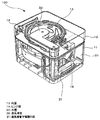
図1は、本発明の実施の形態1に係る加熱調理器の外観斜視図である。本実施の形態1では、加熱調理器が炊飯器100である場合を例に説明する。図2は、炊飯器100の概略内部構成を示す透視斜視図、図3は、下部筐体11から水槽20を取り外した状態を示す外観斜視図である。なお、図1、図2、図3を含めこれ以降で説明する図面においては、主要部を中心に説明するため、各構成部材の大小関係が一部実際のものと異なる場合がある。
Embodiment 1 FIG.
FIG. 1 is an external perspective view of a heating cooker according to Embodiment 1 of the present invention. In the first embodiment, a case where the heating cooker is the
図1〜図3において、炊飯器100は、下部筐体11と、ヒンジ部14を介して下部筐体11の上面開口部を開閉自在に覆うようにして設けられた上部蓋12とを備えている。下部筐体11は、被加熱物(米や水など)を入れるための内鍋15と、この内鍋15を加熱するための誘導加熱コイルなどの図示しない加熱手段を収容している。上部蓋12の内側には内蓋13が設置されており、この内蓋13は上部蓋12を閉めたときに内鍋15の上部開口部を閉塞する役割を果たす。加熱手段にて加熱される被加熱物より発生する蒸気を回収し、この蒸気を復水して溜めるための水槽20が下部筐体11の外周壁面に設置され、水槽20と内鍋15とを連通する蒸気導管30が上部蓋12に設けられている。
1 to 3, a
上部蓋12を閉めると、下部筐体11と上部蓋12とは図示しない係合部によって固定され、上部蓋12は上方向に移動しないようにロックされた状態となる。上部蓋12を開ける際には、下部筐体11に設けられたロック解除ボタン18を押下する。このようにすることで、下部筐体11と上部蓋12との係合が解除されて上部蓋12を開けることができる。
When the
図3では上部蓋12を開けた状態を示しており、上部蓋12の図示を省略している。図3において、下部筐体11の外周壁面には、水槽20を設置するための空間として水槽収納部21が設けられている。水槽収納部21は水槽20を嵌合可能な形状に底面及び側面が形成されており、この水槽収納部21に水槽20を押し込むことで、炊飯器100の正面101側に水槽20を設置するような構成となっている。なお、ここで炊飯器100の正面101とは、炊飯器100の側面の中で使用者が炊飯器100を操作し易い方向のことであり、使用者が使用する際に向き合う炊飯器100の側面である。本実施の形態1では、このような炊飯器100の正面101側の上部蓋12に、使用者が炊飯器100の動作を確認する後述の表示部16及び炊飯器100の操作を行う後述の操作部17を設けている。なお、上部蓋12に解除ボタン18を設け、該解除ボタン18を設けた側面と対向する側面側にヒンジ部14を設けることで、使用者が上部蓋12の開閉および内鍋15内の被調理物の出し入れが容易になるので、ヒンジ部14を設けた下部筐体11の側面に対向する下部筐体11の側面側を炊飯器100の正面101側としても良い。また、炊飯器100の天面側である上部蓋12に表示部16を備える炊飯器100の場合、表示部16の文字が見易い方向(文字に対向する方向)を正面101側としても良い。
FIG. 3 shows a state in which the
水槽20は下部筐体11から取り外し自在であり、水槽20を設置する場合には、水槽20を下部筐体11の方向に押し込んで水槽収納部21に嵌合させる。水槽20を嵌合させると、図1に示すように水槽20と下部筐体11とが一体化される。そして水槽20を引き出すと、下部筐体11から水槽20を取り外すことができる。
The
また、図2に示すように、内蓋13と水槽20を接続するようにして蒸気導管30が設けられている。蒸気導管30は、内鍋と水槽20とを連通しており、内鍋15の中で発生した蒸気を水槽20へと導く。蒸気導管30の水槽20に接続された方の端部には、蒸気導管下端開口部31が形成されている。蒸気導管下端開口部31は水槽20の内部にその開口部を向けている。したがって、内鍋15から発生した蒸気は、蒸気導管30により導かれ、蒸気導管下端開口部31を通って水槽20へと進入することとなる。
Further, as shown in FIG. 2, a
また、図1において、上部蓋12の上面には、炊飯器100の設定内容や運転状態などを表示するための表示部16及び、炊飯器100に対する入力を行うための操作部17が設けられている。表示部16は、LED(light−emitting diode:発光ダイオード)や、液晶ディスプレイ、蛍光管、エレクトロルミネセンス、プラズマディスプレイ等で構成されている。操作部17は、炊飯スイッチや、予約調理を行うためのスイッチなど、各種の操作スイッチで構成されている。なお、表示部16と操作部17とを一体的に形成する構成とすることもできる。また、表示部16と操作部17は、炊飯器100の天面から見て、大半の部分が水槽20と重なる位置に配置されている。
Moreover, in FIG. 1, the
次に、本実施の形態1に係る炊飯器100の動作について説明する。
炊飯調理を行う場合には、下部筐体11から水槽20を取り外し、水槽20の中に冷却水としての水を所定量入れて下部筐体11に設置する。このとき、蒸気導管下端開口部31が、水槽20の中の水に浸漬された状態となるように冷却水を入れる。冷却水の量(深さ)は、蒸気の気泡が浮き上がる速度より蒸気が冷やされて水に戻る速度の方が速くなるように設定する。
Next, operation | movement of the
When cooking rice, the
そして、内鍋15に被加熱物である米と米の量に応じた水とを入れ、下部筐体11に収容する。上部蓋12を閉めてから操作部17の炊飯スイッチをONすると、加熱手段(図示せず)による加熱が開始されて炊飯工程が開始される。炊飯工程が開始されてから所定時間が経過すると、内鍋15内の水が沸騰し、この沸騰により内鍋15内に蒸気が発生する。
And the rice which is a to-be-heated material and the water according to the quantity of the rice are put into the
発生した蒸気は、蒸気導管30により水槽20へと導かれる。蒸気の出口となる蒸気導管下端開口部31は水槽20内の冷却水に一定の深さまで浸漬されているため、蒸気は水槽20内の冷却水の中へと有効に放出され、冷却水と十分に接触しながら結露して水となる。したがって、内鍋15内で発生した蒸気はすべて水槽20に回収することができ、蒸気が炊飯器100の外部に漏れ出るのを防ぐことができる。そして、炊飯が進むにつれて次第に水槽20内の水の量が増加し、その水位は徐々に上昇していく。
The generated steam is guided to the
炊飯が終了すると、水槽20を引き出して下部筐体11から取り外し、水槽20内の水を廃棄する。水槽20内には、炊飯過程で発生した蒸気とともにおねば(米と水の混合物)が混入する可能性があるので、炊飯を行うたびに水槽20内の水を廃棄することが望ましい。このようにすることで、水槽20内の水の腐敗を予防することができる。
When rice cooking is completed, the
上記の通り炊飯器100で炊飯を行う場合においては、炊飯前には冷却水を入れた水槽20を下部筐体11に設置し、炊飯後には溜めた水を廃棄するために水槽20を取り外さなければならない。したがって、水が入った水槽20の着脱を頻繁に行わなければならず、水槽20内の水を誤ってこぼしてしまう可能性も高い。
When cooking rice with the
水槽20を下部筐体11に設けた場合、水槽20を取り付ける際には水槽20を押し込むので下部筐体11の方向に力が加わることとなる。このとき、強く押し込んで水槽20を揺らしてしまうなどして水槽20内の水がこぼれた場合、下部筐体11の方向に水が飛ぶ可能性が高く、また、重力の関係上、水が飛び出した箇所(即ち、水槽20の上縁部付近の位置)よりも下方に水が移動する。したがって、こぼれた水は、下部筐体11における水槽20の高さ位置よりも低い位置に付着する可能性が高い。
When the
本実施の形態1に係る炊飯器100によれば、表示部16及び操作部17を、水槽20が配置される位置よりも上方にある上部蓋12の上面に設置したので、水槽20内の水がこぼれたとしても表示部16や操作部17に水が飛び散るのを防ぐことができる。このため、表示部16や操作部17が水槽20内の水によりショートするのを回避することができる。
According to the
また、炊飯器のような加熱調理器は多くの場合、目の高さよりも低い位置に設置して使用することが多い。このため、上部蓋12の上面に表示部16や操作部17を配置することでこれらの視認性も高まり、使い勝手を向上させることができる。
また、蒸気を外部に放出しない炊飯器は、蒸気を外部に放出する通常の炊飯器よりも炊飯器100内の温度が上昇し易いため、比較的熱に弱い部品を使用している表示部16や操作部17は、熱源である内鍋15との間(直上も含む)に断熱材など熱の伝わりを抑制する手段を設けるなどの対策が必要であった。そこで、実施の形態1に示す炊飯器では、表示部16や操作部17の少なくとも一部を比較的温度が低い水槽20の直上に設けることにより、表示部16や操作部17の温度上昇を抑制し、それらが高温になることによって発生する故障を減少させている。これにより、使用する断熱材の量を減らしたり無くすことができるので、構造をコンパクトにすることができたり、製造コストを抑制することができる。
Moreover, in many cases, a cooking device such as a rice cooker is often used by being installed at a position lower than the eye level. For this reason, by arranging the
Moreover, since the temperature in the
実施の形態2.
図4は、本実施の形態2に係る炊飯器100aの外観斜視図である。前述の実施の形態1では、水槽20を下部筐体11の正面101側に配置した場合の例について説明したが、本実施の形態2では、水槽20を下部筐体11の正面101側を除く側面側に配置した場合の例について説明する。また、図2においては、前述の実施の形態1と同じ構成要素には同じ符号を付している。
Embodiment 2. FIG.
FIG. 4 is an external perspective view of
図4の炊飯器100aにおいては、水槽20aは、下部筐体11の右側面側に配置されている。そして、前述の実施の形態1と同様に、図示しない蒸気導管30によって内鍋15内の蒸気が水槽20aに導かれ、水槽20a内で蒸気が復水して貯められる構成となっている。そして、表示部16と操作部17は上部蓋12の上面に設けられている。
In the
このように本実施の形態2に係る炊飯器100aでは、表示部16及び操作部17を、水槽20aが配置される位置よりも上方にある上部蓋12の上面に設置したので、水槽20aの着脱によって水がこぼれたとしても表示部16や操作部17に水が飛び散るのを防ぐことができる。このため、表示部16や操作部17が水槽20a内の水によりショートするのを回避することができる。
Thus, in the
実施の形態3.
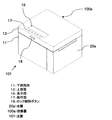
図5は、本実施の形態3に係る炊飯器100bの外観斜視図である。本実施の形態3では、水槽20bの底面積を大きくして高さを低くした場合の構成例について説明する。なお、本実施の形態3では、前述の実施の形態1と同じ構成要素には同じ符号を付している。
Embodiment 3 FIG.
FIG. 5 is an external perspective view of
図5の炊飯器100bにおいて、水槽20bは、その底面積を大きくして高さを低くすることにより、所定の水量を貯めることのできる容積を確保している。そして水槽20bは、下部筐体11の下部に形成した図示しない水槽収納部に嵌合して下部筐体11の下部に設置する構成となっている。表示部16及び操作部17は、下部筐体11の側面外周壁面でかつ水槽20bが設置された位置よりも上方位置に設けている。
In the
このように本実施の形態3に係る炊飯器100bでは、水槽20bを下部筐体11に設け、表示部16及び操作部17を水槽20bが配置される位置よりも上方の下部筐体11の側面に設置したので、炊飯動作(加熱動作)後の場合には内部の水が増加している水槽20bの着脱によって水がこぼれたとしても表示部16や操作部17に水が飛び散るのを防ぐことができる。このため、表示部16や操作部17が水槽20b内の水によりショートするのを回避することができる。
Thus, in the
さらに、表示部16及び操作部17を下部筐体11の側面の外周壁面に設けたので、炊飯器100bをやや高い位置に設置して使用する場合でも、表示部16や操作部17の視認性を確保することができ、使い勝手を向上させることができる。
Furthermore, since the
実施の形態4.
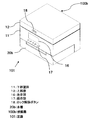
図6は、本実施の形態4に係る炊飯器100cの外観斜視図である。前述の実施の形態1〜3においては、下部筐体11の外周壁面もしくは底面に水槽20を嵌合するための水槽収納部21を形成し、この水槽収納部21に水槽20を押し込んで設置していた。本実施の形態4では、下部筐体11の内部に水槽20を上方から挿入して収納する水槽収納部21cを設けて水槽20cを設置する場合の例について説明する。なお、本実施の形態4では、前述の実施の形態1と同じ構成要素には同じ符号を付している。
Embodiment 4 FIG.
FIG. 6 is an external perspective view of
図6の炊飯器100cにおいて、下部筐体11には、内鍋15を設置する位置と隣接して、上部を開口した水槽収納部21cが形成されている。水槽収納部21cは、水槽20cを嵌合可能な底面積及び高さで形成されている。水槽20cにはその上部に折り畳み可能な取っ手22が設けられており、ユーザはこの取っ手22を掴んで下方向へ押し込みあるいは上方向へ引き出すことにより、水槽20cの着脱を行うことができる。また、図6では図示されていないが、表示部16と操作部17は前述の実施の形態1と同様にして上部蓋12の上面に設置されている。上部蓋12を閉めると、内鍋15を設置するための開口部と水槽収納部21cの開口部の両方が、上部蓋12によって覆われることとなる。
In the
上記のように構成した炊飯器100cにおいて水槽20cを着脱する際には、上部蓋12を開け、取っ手22を掴んで水槽収納部21cに上から押し込みあるいは引出す。このとき、例えば水槽20cを強く押し込むなどして水槽20c及び内部の水が大きく揺れると、水槽20cの上部から上方向に向かって水が飛び出す可能性がある。もし、表示部16及び操作部17が下部筐体11の正面101側の側面に配置した場合、水槽20cから飛び出した水が表示部16及び操作部17に飛び散ってしまいショートしてしまう。しかしながら、本発明の実施の形態4では、水槽20cを着脱する際には上部蓋12は開けられた状態であるので、水槽20cは内蓋13と対面する形となり、表示部16及び操作部17を設けた上部蓋12の上面は、水槽20cに対してちょうど裏側に位置する形となる。このため、水槽20cの着脱により水が飛び出した場合でも、表示部16や操作部17に水が飛び散るのを回避することができる。
When attaching and detaching the
このように本実施の形態4に係る炊飯器100cでは、表示部16及び操作部17を、水槽20cが配置される位置よりも上方にある上部蓋12の上面に設置したので、水槽20cの着脱によって水がこぼれたとしても表示部16や操作部17に水が飛び散るのを防ぐことができる。このため、表示部16や操作部17が水槽20c内の水によりショートするのを回避することができる。
Thus, in the
なお、上記説明では加熱調理器が炊飯器である場合の例について説明したが、本発明の適用は炊飯器に限るものではない。本発明は、発生した蒸気を復水して回収するような様々な加熱調理器に適用することができ、同様の効果を得ることができる。また、上記説明では、上部蓋が前後に開閉する場合の例について説明したが、上部蓋は左右に開くように構成することもでき、同様の効果を得ることができる。 In addition, although the said description demonstrated the example in case a heating cooker is a rice cooker, application of this invention is not restricted to a rice cooker. The present invention can be applied to various cooking devices such as condensing and recovering generated steam, and the same effect can be obtained. In the above description, an example in which the upper lid opens and closes forward and backward has been described. However, the upper lid can also be configured to open to the left and right, and the same effect can be obtained.
11 下部筐体、12 上部蓋、13 内蓋、14 ヒンジ部、15 内鍋、16 表示部、17 操作部、18 ロック解除ボタン、20 水槽、21 水槽収納部、22 取っ手、30 蒸気導管、31 蒸気導管下端開口部、100 炊飯器、101 正面。
DESCRIPTION OF
Claims (8)
前記加熱容器内で発生する蒸気を前記加熱容器外へと導く水蒸気案内路と、
前記水蒸気案内路により導かれた蒸気を回収し復水して貯える着脱可能な水槽と、
加熱調理に関する入力を行う操作部とを備え、
前記操作部を前記水槽よりも上方に設置した
ことを特徴とする加熱調理器。 A heating container for storing an object to be heated;
A water vapor guide path for guiding the steam generated in the heating container to the outside of the heating container;
A detachable water tank for collecting and condensing and storing the steam guided by the water vapor guide path,
An operation unit for performing input related to cooking,
The cooking device, wherein the operation unit is installed above the water tank.
前記加熱容器内で発生する蒸気を前記加熱容器外へと導く水蒸気案内路と、
前記水蒸気案内路により導かれた蒸気を回収し復水して貯える着脱可能な水槽と、
加熱調理に関する情報を表示する表示部とを備え、
前記表示部を前記水槽よりも上方に設置した
ことを特徴とする加熱調理器。 A heating container for storing an object to be heated;
A water vapor guide path for guiding the steam generated in the heating container to the outside of the heating container;
A detachable water tank for collecting and condensing and storing the steam guided by the water vapor guide path,
A display unit for displaying information on cooking,
The cooking device, wherein the display unit is installed above the water tank.
前記下部筐体の上面開口部を開閉自在に覆う上部蓋とを有し、
前記水槽を前記下部筐体側に配置して、
前記操作部を前記上部蓋に設置した
ことを特徴とする請求項1記載の加熱調理器。 A lower housing for accommodating and supporting the heating container;
An upper lid that covers the upper surface opening of the lower housing so as to be freely opened and closed;
Arranging the water tank on the lower housing side,
The cooking device according to claim 1, wherein the operation unit is installed on the upper lid.
ことを特徴とする請求項1もしくは請求項3に記載の加熱調理器。 The cooking device according to claim 1 or 3, wherein the operation unit is disposed on a front side of the cooking device of the upper lid.
前記下部筐体の上面開口部を開閉自在に覆う上部蓋とを有し、
前記水槽を前記下部筐体側に配置して、
前記表示部を前記上部蓋に設置した
ことを特徴とする請求項2記載の加熱調理器。 A lower housing for accommodating and supporting the heating container;
An upper lid that covers the upper surface opening of the lower housing so as to be freely opened and closed;
Arranging the water tank on the lower housing side,
The cooking device according to claim 2, wherein the display unit is installed on the upper lid.
ことを特徴とする請求項2もしくは請求項5に記載の加熱調理器。 The cooking device according to claim 2 or 5, wherein the display unit is arranged on a front side of the cooking device of the upper lid.
少なくとも一部が重なる位置に配置した
ことを特徴とする請求項1、請求項3、請求項4のいずれかに記載の加熱調理器。 The said operation part and the said water tank have been arrange | positioned in the position where at least one part overlaps seeing from the top | upper surface of the said heating cooker, The heating in any one of Claim 1, Claim 3 and Claim 4 characterized by the above-mentioned. Cooking device.
少なくとも一部が重なる位置に配置した
ことを特徴とする請求項2、請求項5、請求項6のいずれかに記載の加熱調理器。 The said display part and the said water tank have been arrange | positioned in the position where at least one part overlaps seeing from the top | upper surface of the said heating cooker, The heating in any one of Claim 2, Claim 5 and Claim 6 characterized by the above-mentioned. Cooking device.
Priority Applications (1)
| Application Number | Priority Date | Filing Date | Title |
|---|---|---|---|
| JP2008210463A JP2010046115A (en) | 2008-08-19 | 2008-08-19 | Cooker |
Applications Claiming Priority (1)
| Application Number | Priority Date | Filing Date | Title |
|---|---|---|---|
| JP2008210463A JP2010046115A (en) | 2008-08-19 | 2008-08-19 | Cooker |
Related Child Applications (2)
| Application Number | Title | Priority Date | Filing Date |
|---|---|---|---|
| JP2010283624A Division JP5159871B2 (en) | 2010-12-20 | 2010-12-20 | Cooker |
| JP2011118443A Division JP2011156425A (en) | 2011-05-26 | 2011-05-26 | Cooker |
Publications (2)
| Publication Number | Publication Date |
|---|---|
| JP2010046115A true JP2010046115A (en) | 2010-03-04 |
| JP2010046115A5 JP2010046115A5 (en) | 2010-04-15 |
Family
ID=42063742
Family Applications (1)
| Application Number | Title | Priority Date | Filing Date |
|---|---|---|---|
| JP2008210463A Pending JP2010046115A (en) | 2008-08-19 | 2008-08-19 | Cooker |
Country Status (1)
| Country | Link |
|---|---|
| JP (1) | JP2010046115A (en) |
Citations (3)
| Publication number | Priority date | Publication date | Assignee | Title |
|---|---|---|---|---|
| JPS60106532U (en) * | 1983-12-26 | 1985-07-20 | 株式会社日立ホームテック | Steam recovery device for rice cooker |
| JPH06217866A (en) * | 1993-01-27 | 1994-08-09 | Mitsubishi Electric Home Appliance Co Ltd | Rice cooker |
| JP2000161709A (en) * | 1998-11-26 | 2000-06-16 | Corona Corp | Drain tank of dehumidifier |
-
2008
- 2008-08-19 JP JP2008210463A patent/JP2010046115A/en active Pending
Patent Citations (3)
| Publication number | Priority date | Publication date | Assignee | Title |
|---|---|---|---|---|
| JPS60106532U (en) * | 1983-12-26 | 1985-07-20 | 株式会社日立ホームテック | Steam recovery device for rice cooker |
| JPH06217866A (en) * | 1993-01-27 | 1994-08-09 | Mitsubishi Electric Home Appliance Co Ltd | Rice cooker |
| JP2000161709A (en) * | 1998-11-26 | 2000-06-16 | Corona Corp | Drain tank of dehumidifier |
Similar Documents
| Publication | Publication Date | Title |
|---|---|---|
| JP4334575B2 (en) | Steam processing equipment | |
| CN101273848B (en) | Heating cooker | |
| JP4612062B2 (en) | rice cooker | |
| JP2009165643A (en) | Rice cooker | |
| JP5159871B2 (en) | Cooker | |
| JP4906813B2 (en) | Cooker | |
| JP2011156425A (en) | Cooker | |
| JP4884444B2 (en) | Cooker | |
| JP2010046115A (en) | Cooker | |
| JP6138219B2 (en) | Cooker | |
| JP5247786B2 (en) | rice cooker | |
| JP6664060B2 (en) | rice cooker | |
| JP5030980B2 (en) | Cooker | |
| JP2010046121A (en) | Cooker | |
| JP5345177B2 (en) | Cooker | |
| JP2010277905A (en) | Induction heating cooker | |
| JP2009030874A (en) | Steam cooker | |
| JP5893067B2 (en) | Cooker | |
| KR20170052913A (en) | Drain Pan Assembly For Electric Rice Cooker | |
| CN113795183A (en) | Food processor | |
| JP2000000162A (en) | Rice cooker | |
| JP2012049009A (en) | Heating cooker | |
| JP7360011B2 (en) | rice cooker | |
| JP7401773B2 (en) | Electric pot | |
| JP2023141040A (en) | Cooker |
Legal Events
| Date | Code | Title | Description |
|---|---|---|---|
| A521 | Written amendment |
Effective date: 20100127 Free format text: JAPANESE INTERMEDIATE CODE: A523 |
|
| A871 | Explanation of circumstances concerning accelerated examination |
Free format text: JAPANESE INTERMEDIATE CODE: A871 Effective date: 20100127 |
|
| A977 | Report on retrieval |
Free format text: JAPANESE INTERMEDIATE CODE: A971007 Effective date: 20100610 |
|
| A131 | Notification of reasons for refusal |
Effective date: 20100622 Free format text: JAPANESE INTERMEDIATE CODE: A131 |
|
| A975 | Report on accelerated examination |
Effective date: 20100608 Free format text: JAPANESE INTERMEDIATE CODE: A971005 |
|
| A521 | Written amendment |
Effective date: 20100820 Free format text: JAPANESE INTERMEDIATE CODE: A523 |
|
| A02 | Decision of refusal |
Effective date: 20101019 Free format text: JAPANESE INTERMEDIATE CODE: A02 |
|
| A521 | Written amendment |
Effective date: 20110526 Free format text: JAPANESE INTERMEDIATE CODE: A523 |