JP2010044973A - Electromagnetic relay - Google Patents
Electromagnetic relay Download PDFInfo
- Publication number
- JP2010044973A JP2010044973A JP2008209264A JP2008209264A JP2010044973A JP 2010044973 A JP2010044973 A JP 2010044973A JP 2008209264 A JP2008209264 A JP 2008209264A JP 2008209264 A JP2008209264 A JP 2008209264A JP 2010044973 A JP2010044973 A JP 2010044973A
- Authority
- JP
- Japan
- Prior art keywords
- electromagnetic relay
- base
- press
- actuator
- bus bar
- Prior art date
- Legal status (The legal status is an assumption and is not a legal conclusion. Google has not performed a legal analysis and makes no representation as to the accuracy of the status listed.)
- Granted
Links
- XEEYBQQBJWHFJM-UHFFFAOYSA-N Iron Chemical group [Fe] XEEYBQQBJWHFJM-UHFFFAOYSA-N 0.000 claims description 28
- 230000004907 flux Effects 0.000 claims description 6
- 230000000149 penetrating effect Effects 0.000 claims description 4
- 230000009471 action Effects 0.000 claims description 2
- 239000000758 substrate Substances 0.000 description 10
- 238000010438 heat treatment Methods 0.000 description 3
- 239000011347 resin Substances 0.000 description 3
- 229920005989 resin Polymers 0.000 description 3
- 230000000694 effects Effects 0.000 description 2
- 238000012544 monitoring process Methods 0.000 description 2
- 238000000926 separation method Methods 0.000 description 2
- 238000005476 soldering Methods 0.000 description 2
- 230000008901 benefit Effects 0.000 description 1
- 230000008859 change Effects 0.000 description 1
- 238000006073 displacement reaction Methods 0.000 description 1
- 230000005611 electricity Effects 0.000 description 1
- 230000005484 gravity Effects 0.000 description 1
- 230000017525 heat dissipation Effects 0.000 description 1
- 230000020169 heat generation Effects 0.000 description 1
- 229910052742 iron Inorganic materials 0.000 description 1
- 230000004048 modification Effects 0.000 description 1
- 238000012986 modification Methods 0.000 description 1
- 230000001105 regulatory effect Effects 0.000 description 1
- 230000004044 response Effects 0.000 description 1
- 230000006641 stabilisation Effects 0.000 description 1
- 238000011105 stabilization Methods 0.000 description 1
Images


Classifications
-
- H—ELECTRICITY
- H01—ELECTRIC ELEMENTS
- H01H—ELECTRIC SWITCHES; RELAYS; SELECTORS; EMERGENCY PROTECTIVE DEVICES
- H01H51/00—Electromagnetic relays
- H01H51/22—Polarised relays
- H01H51/2227—Polarised relays in which the movable part comprises at least one permanent magnet, sandwiched between pole-plates, each forming an active air-gap with parts of the stationary magnetic circuit
-
- H—ELECTRICITY
- H01—ELECTRIC ELEMENTS
- H01H—ELECTRIC SWITCHES; RELAYS; SELECTORS; EMERGENCY PROTECTIVE DEVICES
- H01H1/00—Contacts
- H01H1/58—Electric connections to or between contacts; Terminals
- H01H2001/5877—Electric connections to or between contacts; Terminals with provisions for direct mounting on a battery pole
Abstract
Description
本発明は電磁継電器、特に、大電流の通電および遮断が可能な電磁継電器に関する。 The present invention relates to an electromagnetic relay, and more particularly to an electromagnetic relay capable of energizing and interrupting a large current.
電磁継電器としては、車両用バッテリーなどからの大電流の通電が可能なものがある。このような電磁継電器は、緊急時に電流を遮断するなどの目的で用いられている。 Some electromagnetic relays can be energized with a large current from a vehicle battery or the like. Such an electromagnetic relay is used for the purpose of interrupting current in an emergency.
大電流の通電が可能な電磁継電器は、可動接点の動作量や動作力を大きくする必要があること、発熱量が多くなり、放熱性を確保してやる必要があること、開閉される接点の耐久性を確保する必要があること、などから、大型化しやすい。そこで、特許文献1,2に見られるように、大電流の通電が可能な電磁継電器を小型化しようとする種々の試みがなされてきている。
Electromagnetic relays that can be energized with a large current need to increase the operating amount and operating force of the movable contact, increase the amount of heat generation, and ensure heat dissipation, and durability of the contacts that are opened and closed Because it is necessary to ensure, it is easy to enlarge. Therefore, as seen in
本発明の目的は、大電流の通電および遮断が可能でありながら、小型化が可能な新規な構造の電磁継電器を提供することにある。 An object of the present invention is to provide an electromagnetic relay having a novel structure that can be reduced in size while being capable of energizing and interrupting a large current.
上述の目的を達成するため、本発明による電磁継電器は、電磁石部と、電磁石部の発生する磁界の作用によって移動させられるアマチュアが取り付けられたアクチュエータと、アクチュエータに係合されて、アマチュアの移動に応じて変位させられる可動ばねと、可動ばねに取り付けられた可動接点と、可動接点が、アマチュアの移動に応じて、接触させられた状態と、離隔された状態とに切り替えられる固定接点と、を有し、アクチュエータは、アマチュアの移動に応じて旋回するように保持され、旋回軸線に垂直な面における形状がL字形状であり、L字形状の一端に旋回軸線が位置し、L字形状の他端側に、アマチュア、および可動ばねとの係合部が設けられていることを特徴とする。 In order to achieve the above object, an electromagnetic relay according to the present invention includes an electromagnet part, an actuator attached with an armature that is moved by the action of a magnetic field generated by the electromagnet part, and an actuator that engages the actuator to move the armature. A movable spring that is displaced in response, a movable contact that is attached to the movable spring, and a fixed contact that is switched between a contacted state and a separated state according to the movement of the amateur. And the actuator is held so as to turn according to the movement of the amateur, and the shape in a plane perpendicular to the turning axis is L-shaped, the turning axis is located at one end of the L-shape, and the L-shaped An engaging portion with an amateur and a movable spring is provided on the other end side.
この構成によれば、アクチュエータの大きさを最大限に利用して、その旋回軸線からアマチュア、および、可動ばねとの係合部への距離を効率的に長くすることができる。旋回軸線からアマチュアへの距離を長くすることによって、可動ばねを動かすのに必要なトルクを得るために電磁石部とアマチュアによって発生する必要がある力を低減し、電磁継電器の小型化に寄与することができる。旋回軸線から、可動ばねとの係合部への距離を長くすることによって、可動接点を固定接点から電気的に有効に遮断するのに必要な量だけ可動接点を動作させるのに必要な、アマチュアの長さおよび旋回角度を低減することができ、それによって、電磁継電器の小型化に寄与することができる。これらの作用は、特に、大電流が通電される大型化しやすい電磁継電器の場合に、有効に得られる。 According to this configuration, the distance from the pivot axis to the armature and the engaging portion with the movable spring can be effectively increased by making the maximum use of the size of the actuator. By increasing the distance from the swivel axis to the amateur, the force required to be generated by the electromagnet and the armature to obtain the torque required to move the movable spring is reduced, contributing to the miniaturization of the electromagnetic relay. Can do. The armature required to operate the movable contact by the amount necessary to electrically cut off the movable contact from the fixed contact by increasing the distance from the pivot axis to the engaging portion with the movable spring. Can be reduced in length and turning angle, thereby contributing to miniaturization of the electromagnetic relay. These effects can be effectively obtained particularly in the case of an electromagnetic relay that is easily increased in size and is energized with a large current.
本発明において、電磁石部は、コイルが巻かれたボビンと、ボビンを貫通する鉄心と、鉄心に連結されたヨークと、を有し、鉄心は、一端でヨークに連結され、他端側が、ヨークと間隔をおいて対面しており、アマチュアは、永久磁石と、永久磁石の各極にそれぞれ接続され磁束経路を形成する部材と、を有し、磁束経路を形成する部材の一方が、鉄心とヨークの、互いに間隔をおいて対面している部分の間に位置している構成とするのが好ましい。 In the present invention, the electromagnet portion includes a bobbin around which a coil is wound, an iron core that passes through the bobbin, and a yoke that is coupled to the iron core. The iron core is coupled to the yoke at one end, and the other end is disposed at the yoke. The amateur has a permanent magnet and a member that is connected to each pole of the permanent magnet to form a magnetic flux path, and one of the members that form the magnetic flux path is an iron core It is preferable that the yoke is located between the portions facing each other at an interval.
このように、アマチュアに永久磁石を設けた有極電磁継電器は、永久磁石の磁力をアマチュアの移動に利用して、電磁石部と協働して発生される力を高めることができる。したがって、有極継電器は、特に、大電流を通電される電磁継電器として適している。また、この構成では、アマチュアは、コイルの非通電磁にも、永久磁石の磁力によって、鉄心および/またはヨークに付着した状態に保持されるので、旋回軸線部分のみで支持されるアクチュエータを安定化することができる。また、前述のように、L字形状のアクチュエータによれば、アマチュアの移動量を比較的大きくすることができる。したがって、永久磁石を有するために、電磁継電器の導通状態と非導通状態に対応する2つの安定した状態間で、比較的長い移動距離が必要なアマチュアを移動させるのに、本発明におけるL字形状のアクチュエータは好都合である。 As described above, the polarized electromagnetic relay in which the permanent magnet is provided on the amateur can increase the force generated in cooperation with the electromagnet unit by using the magnetic force of the permanent magnet for the movement of the amateur. Therefore, the polarized relay is particularly suitable as an electromagnetic relay that is energized with a large current. Further, in this configuration, the armature is maintained in a state where it is attached to the iron core and / or the yoke by the magnetic force of the permanent magnet, even when the coil does not conduct electricity, so that the actuator supported only by the pivot axis portion is stabilized. can do. Further, as described above, according to the L-shaped actuator, the amount of movement of the amateur can be made relatively large. Therefore, in order to have a permanent magnet, the L-shape of the present invention is used to move an amateur that requires a relatively long moving distance between two stable states corresponding to the conductive state and the non-conductive state of the electromagnetic relay. The actuator is convenient.
また、電磁石部、可動ばね、および、固定接点を支持する部材は、共通のベースに圧入されて保持されており、アクチュエータは、ベースの穴部に挿入されたシャフトを有し、シャフトを中心として旋回する構成とするのが好ましい。このように、共通のベースによって、各部品を保持する構成とすることによって、別途の支持部品を不要とし、電磁継電器の小型化に寄与することができる。 Further, the electromagnet part, the movable spring, and the member supporting the fixed contact are press-fitted and held in a common base, and the actuator has a shaft inserted into the hole of the base, and the shaft is the center. It is preferable to use a structure that turns. As described above, the configuration in which each component is held by the common base eliminates the need for a separate support component and contributes to the miniaturization of the electromagnetic relay.
各部品をベースに圧入によって保持する場合、ベースには、電磁石部の圧入される部分に、電磁石部の、圧入方向に交差する方向に延びるように形成された穴に嵌合する突起が形成された嵌合片を突出するように形成するのが好ましい。電磁石部は、比較的重いものとなりやすいので、このように、嵌合片を用いて電磁石部の保持の安定化を図るのが好ましい。 When each part is held in the base by press-fitting, the base is formed with a protrusion that fits into a hole formed to extend in a direction intersecting the press-fitting direction of the electromagnet part in the press-fitted part of the electromagnet part. Preferably, the fitting piece is formed so as to protrude. Since the electromagnet portion is likely to be relatively heavy, it is preferable to stabilize the holding of the electromagnet portion using the fitting piece as described above.
また、固定接点は、板部が、その板厚方向に垂直な方向に、ベースに形成された溝内に圧入されたバスバー端子に取り付けた構成とすることができる。電磁石部は、コイルが巻かれた筒部と筒部の端部に連結されたフランジを備えるボビンを有する構成とすることができ、バスバー端子と電磁石部は、ベースの同じ側面からベースに圧入する構成とし、バスバー端子の板部の、ベースに圧入される側と反対側の縁には、フランジの、ベースに圧入される側と反対側の縁に当接するように延びる押さえ部を形成することができる。この構成によれば、バスバー端子に、それをベースに圧入することによって働く保持力を、電磁石部の保持に利用して、電磁石部の保持の安定化を図ることができる。特に、大電流を流す電磁継電器の場合、バスバー端子は、比較的大きなものとなり、したがって、その保持力は比較的大きくなるので、電磁石部の保持の安定化を有効に達成することができる。 Further, the fixed contact may be configured such that the plate portion is attached to a bus bar terminal press-fitted into a groove formed in the base in a direction perpendicular to the plate thickness direction. The electromagnet part may be configured to have a bobbin including a cylindrical part wound with a coil and a flange connected to an end part of the cylindrical part, and the bus bar terminal and the electromagnet part press fit into the base from the same side surface of the base A holding portion that extends to abut the edge of the flange opposite to the side that is press-fitted into the base is formed on the edge of the bus bar terminal plate that is opposite to the side that is press-fitted into the base. Can do. According to this configuration, it is possible to stabilize the holding of the electromagnet part by using the holding force that works by press-fitting the bus bar terminal into the base to hold the electromagnet part. In particular, in the case of an electromagnetic relay through which a large current flows, the bus bar terminal is relatively large, and therefore the holding force thereof is relatively large, so that stabilization of holding of the electromagnet portion can be effectively achieved.
可動ばねには、平編線を並列に接続するのが好ましい。特に、大電流を流す場合、可動ばねを介した電流経路において、損失を低減し加熱を抑制するために、抵抗を小さく抑える必要があるが、可動ばねに平編線を並列に接続することによって、可動ばねの断面積を抑えながら、抵抗を小さく抑えることができる。可動ばねの断面積を小さく抑えることによって、可動ばねの変位に必要な力を軽減し、電磁継電器の小型化に寄与することができる。 It is preferable to connect a flat knitted wire in parallel to the movable spring. In particular, when flowing a large current, it is necessary to reduce the resistance in order to reduce loss and suppress heating in the current path via the movable spring, but by connecting a flat knitted wire to the movable spring in parallel. The resistance can be reduced while suppressing the cross-sectional area of the movable spring. By suppressing the cross-sectional area of the movable spring to a small value, the force required for the displacement of the movable spring can be reduced, contributing to the miniaturization of the electromagnetic relay.
コイルに接続されるコイル端子は、その板状の先端部に、中央に、板厚方向に貫通する穴が形成され、板厚方向および長手方向に垂直な方向に膨らんだ形状の圧入接続部が形成された構成とするのが好ましい。このような構造の圧入接続部は、基板の接続部に形成した穴内に圧入した時に、膨らんだ形状の部分が、その中央に形成された穴が小さくなるように潰れるようにすることができる。その際、復元力によって、圧入接続部が穴の内面に密着するので、圧入接続部は、圧入するだけで、良好に電気接続可能な構成とすることができる。このような圧入接続部を設けることによって、電磁継電器の実装を容易にすることができ、また、基板に直接実装する構成とすることができるので、ハーネスやコネクタを用いるのに比べて、省スペース化を図ることができる。 The coil terminal to be connected to the coil has a plate-shaped tip portion with a hole penetrating in the thickness direction in the center, and a press-fit connection portion swelled in a direction perpendicular to the thickness direction and the longitudinal direction. A formed structure is preferable. When the press-fit connection portion having such a structure is press-fitted into a hole formed in the connection portion of the substrate, the swelled portion can be crushed so that the hole formed in the center thereof becomes small. At this time, since the press-fit connection portion is brought into close contact with the inner surface of the hole by the restoring force, the press-fit connection portion can be configured to be able to be electrically connected satisfactorily only by press-fitting. By providing such a press-fit connection portion, it is possible to facilitate mounting of the electromagnetic relay, and it can be configured to be directly mounted on the board, so that it can save space compared to using a harness or a connector. Can be achieved.
また、本発明の電磁継電器は、可動接点および固定接点にそれぞれ接続されたバスバー端子から信号端子を引き出した構成とするのが好ましい。それによって、電磁継電器内の構成要素の状態に応じて、バスバー端子間が導通状態となっているか非導通状態となっているかを、信号端子間の導通状態を検出することによって、モニタリングすることが可能となる。 Moreover, it is preferable that the electromagnetic relay of the present invention has a configuration in which the signal terminal is drawn from the bus bar terminal connected to the movable contact and the fixed contact. Thereby, depending on the state of the components in the electromagnetic relay, whether the bus bar terminals are in a conductive state or a non-conductive state can be monitored by detecting the conductive state between the signal terminals. It becomes possible.
信号端子を設ける場合、その先端部にも、コイル端子と同様の圧入接続部を設けるのが好ましい。それによって、電磁継電器の実装を容易にし、実装に必要なスペースを低減する作用が得られる。 When providing a signal terminal, it is preferable to provide the press-fit connection part similar to a coil terminal also in the front-end | tip part. As a result, it is possible to easily mount the electromagnetic relay and to reduce the space required for mounting.
本発明によれば、大電流の通電および遮断が可能でありながら、小型化が可能な電磁継電器を提供することができる。 According to the present invention, it is possible to provide an electromagnetic relay that can be reduced in size while being capable of energizing and interrupting a large current.
以下、図面を参照して本発明の実施形態について説明する。図1は、本実施形態の電磁継電器1を模式的に示す分解斜視図、図2は、組み立てた状態の平面図である。以下の説明では、便宜上、図1における上下などの位置関係を説明に用いることがあるが、この上下方向は、重力の方向と一致している必要はない。
Hereinafter, embodiments of the present invention will be described with reference to the drawings. FIG. 1 is an exploded perspective view schematically showing the
本実施形態の電磁継電器1は、永久磁石95が組み込まれた有極電磁継電器であり、バスバー(母線)端子60,70間を導通させたり、遮断したりする働きする。特に、バスバー端子60,70間には、車載用バッテリーの供給電流が流され、電磁継電器1は、緊急時に電流の供給を遮断する働きをする。
The
電磁継電器1は、上方に向かって開口した箱状のベース10を有している。ベース10は、樹脂モールド製であり、中央の矩形部分と、図1の奥側の外壁13に沿った左側の延長部11および右側の延長部12を備える平面形状を有している。
The
ベース10の上方の開口部は、樹脂モールド製の板状のカバー120によって覆われている。カバー120は、ベース10の中央の矩形部分と左側の延長部11を覆う概ねL字状の形状を有している。カバー120の、右側の延長部12側には、バスバー端子60,70の、後述する板部61,71の上縁をそれぞれ抑えるように下方に突出した突起121,122が形成されている。
The opening above the
バスバー端子60は、ベース10の奥側の外壁13の内面に沿って延びる板部61を有している。ベース10の右側の延長部12には、バスバー端子60の板部61よりも少し狭い幅の溝12aが形成されており、バスバー端子60は、溝12a内に押し込まれている。それにより、バスバー端子60は、ベース10および/またはバスバー端子60の弾性力が加わることによって保持され、すなわち、圧入されている。バスバー端子60の板部61の左側の端部は、ベース10の左側の延長部11の端部まで延びている。図3の、ベース10の平面図に示すように、ベース10の左側の延長部11内には、後述するアクチュエータ80を取り付けるための穴18aを形成する内壁部18と外壁13との間に隙間が形成されている。この隙間に、バスバー端子60の板部61が挟まれて保持されている。
The
また、ベース10の右側の延長部12には、ベース10の矩形部分の右側の外壁14に隣接する部分の底面に凹部12cが形成されている。バスバー端子60の板部61には、凹部12cに対応する位置に切り欠き61aが形成されている。切り欠き61aの鉛直方向に延びる両縁部が、溝12aの、凹部12cに沿った鉛直面と、外壁14の内面とに当接することによって、バスバー端子60は左右方向に位置決めされている。
In addition, a
バスバー端子70も、その板部71が、ベース10の延長部12の、バスバー端子60用の溝12aより、図1での手前側に形成された溝12b内に圧入されて取り付けられている。バスバー端子70の板部71にも切り欠き71aが形成されており、切り欠き71aが、溝12bの、ベース10の延長部12の凹部12cに沿った鉛直面と、外壁14の内面とに当接して、バスバー端子70を左右方向に位置決めしている。
The
バスバー端子60,70の右側の端部には、板部61,71から屈曲させられて水平に延びる接続部62,72がそれぞれ形成されている。接続部62,72は、車載用バッテリーからの給電線などと接続するのに好適な構造を有するものとすることができる。図に示す例では、接続部62,72には円形の開口部62a,72aが形成され、バスバー端子60,70をボルトによって給電側に連結できるようになっている。
バスバー端子70の左側端部は、ベース10の中央付近までしか延びていない。ベース10内には、バスバー端子70の、ベース10内を延びる部分の手前側で、この部分に沿って延びる内壁19が形成されている。内壁19には、ベース10の中央側の端部に、鉛直方向に延びる溝19aが形成されており、バスバー端子70の左側端部が溝19a内に圧入されている。
The left end portion of the
バスバー端子60の板部61の左側端部付近には、鉛直方向に並んで配置された円形の2つの開口部61c,61dが形成されている。同様の円形の開口部63a,63bが一端付近に形成された平編線63と、円形の開口部64a,64bが形成された可動ばね64が、バスバー端子60の板部61の手前側に配置されている。これら平編線63と可動ばね64は、開口部61c,61d,63a,63b,64a,64bに通された2つのリベット67a,67bによって、バスバー端子60に取り付けられている。
Near the left end of the
平編線63と可動ばね64には、開口部63a,63b,64a,64bとは反対側の端部付近にも、鉛直方向に並んで配置された円形の2つずつの開口部63d,63e,64d,64eがそれぞれ形成されている。これらの開口部63d,63e,64d,64eに通された2つのリベット状の可動接点69a,69bによって、平編線63と可動ばね64は、右端側でも連結されている。
The flat knitted
可動接点69a,69bは、バスバー端子70の板部71の左端側に対面する位置に配置されている。バスバー端子70の、可動接点69a,69bに対面する位置には、開口部71b,71cに通されたリベット状の固定接点73a,73bが取り付けられている。可動ばね64の可動接点69a,69bと、バスバー端子70の固定接点73a,73bは、後述するように、互いに接触した状態と離隔した状態とに切り替えられて、バスバー端子60,70間を導通状態と非導通状態とに切り替えるための接点として機能する。
The
ベース10の、図1での手前側には、鉛直にベース10の中間高さまで延びる壁16を境界として、浅底部17が設けられている。壁16と、内壁19との間に、樹脂モールド製のボビン20、鉄製の鉄心40およびヨーク50が組み合わされた電磁石部30が圧入されている。
A
ボビン20は、図1での前後の両端にフランジ22,23が形成された筒部21を有している。図4の、電磁石部30の中心を通る水平断面図に模式的に示すように、筒部21上には、コイル31が巻かれている。図1などでは、わかりやすくするために、コイル31の図示は省略している。フランジ22,23は矩形であり、それらの下辺がベース10の底面に当接し、ボビン20が所定の姿勢で取り付けられるようになっている。
The
ボビン20には、筒部21およびフランジ22,23を通る貫通孔24が形成されており、この貫通孔24内に、鉄心40の棒部41が通されている。貫通孔24と棒部41は、互いに対応する矩形の断面形状を有しており、それによって、鉄心40はボビン20に対して所定の姿勢となるように保持されている。
The
鉄心40の棒部41の、図1での奥側のフランジ23側の端部には、フランジ23に平行に延びる板部42が結合されている。板部42は、図1,4での左方向に、フランジ23を越えて延びている。板部42の下縁の左端付近には、ベース10の底面に形成された凹部10a(図3)に嵌合する突起43が形成されている。
A
ヨーク50は、ボビン20の、図1での手前側のフランジ22に平行に延びる基端板部51を有している。基端板部51には穴54が形成され、この穴54に、鉄心40の棒部41の一端に、フランジ22から突出するように形成された突起44が嵌合している。穴54と突起44は、互いに対応する矩形の断面形状を有しており、それによって、ヨーク50は、鉄心40に対して所定の姿勢となるように保持されている。
The
ヨーク50の基端板部51は、図1,4での左側にフランジ22を越えて延びた後、奥側に折れ曲がって、鉄心40の棒部41に平行に延びる中間板部52に続いている。中間板部52は、再び左側に折れ曲がって、フランジ22,23に平行に延びる先端板部53に続いている。
The base
ヨーク50の先端板部53は、鉄心40の板部42の左端部分と対面している。このようにして、コイル31によって磁界を発生した時に、磁束が鉄心40とヨーク50を介して伝達され、鉄心40の板部42とヨーク50の先端板部53の間に磁界が発生するようになっている。
The front
ヨーク50の基端板部51の下縁には、ベース10の底面に形成された凹部10b,10c(図3)に嵌合する突起55,56が形成されている。中間板部52の上縁には、カバー120の下面に形成された凹部(不図示)に嵌合する突起57が形成されている。また、中間板部52には穴58が形成されており、図4のA−A線に沿った部分の断面図である図5に示すように、ベース10の底面から鉛直に延びる嵌合片10dの上端の突起10eが、中間板部52の穴58内に嵌合している。さらに、バスバー端子70の板部71の上縁に、図1での手前側に折れ曲がるように形成された押さえ部71dが、ボビン20のフランジ部23の上縁に当接して、ボビン20を押さえるようになっている。
On the lower edge of the base
これらの構成によって、比較的重いものとなりやすい電磁石部30が、ベース10に安定して保持されるようになっている。なお、ベース10の嵌合片10dのような構成は、ボビン20のフランジ22,23や鉄心40に形成した穴に嵌合する構成としてもよい。また、穴58は、図示する例では、圧入方向に垂直な方向に延びているが、一般には、電磁石部30を保持する作用が得られる、圧入方向に交差する方向であれば、どの方向に延びる構成としてもよい。
With these configurations, the
コイル31には、4つのコイル端子35が接続されている。コイル31は、コイル端子35のうちの一対に電流を流すと一方向に磁界を発生し、他の一対に電流を流すと反対方向に磁界を発生するようになっている。
Four
ボビン20には、コイル端子35が取り付けられた端子保持部25が一体に形成されている。端子保持部25は、ボビン20の、図1での手前側のフランジ22の上縁から手前側に突出しており、フランジ22よりも左側に延長されている。端子保持部25の左端側には段差部が形成されて手前側が低段部25aとなっており、段差部の鉛直壁には、各コイル端子35の一端がそれぞれ挿入される4つの穴25bが左右に間隔をおいて並んで形成されている。
The
各コイル端子35は、低段部25aの上面に沿って延び、穴25b内に挿入されている基端板部35aを有している。基端板部35aからは、手前側の部分で下方に向かって折れ曲がって先端板部35bが続いている。先端板部35bは、ベース10の浅底部17の底面に形成された各穴17aを通ってベース10の外部に突出している。
Each
コイル端子35の基端板部35aには、穴25bからちょうど出る位置に鉛直方向に延びる棒部35cが形成されている。棒部35cは、コイル端子35を穴25b内に挿入する際のストッパとして機能する。
The base
また、棒部35cには、図示していないが、コイル31の一端が巻き付けられて接続されている。端子保持部25の右側部分の上面には、コイル31の、各コイル端子35に接続される引き出し部がそれぞれ引っ掛けられる4つの突起25cが形成されている。突起25cに引っ掛けることによって、コイル31の引き出し部を、筒部21から離れるように延びる部分が生じるのを抑制して、筒部21の、フランジ22側の端部付近から適切に引き出すことができるようになっている。
Although not shown, one end of the
各コイル端子35の先端板部35bには、横方向に膨らんだ形状の圧入接続部35dが形成され、圧入接続部35dの中央に、板厚方向に貫通する穴35eが形成されている。圧入接続部35dは、横方向に膨らんだ部分が、基板などの接続穴よりも少し大きな外形を有しており、接続穴内に押し込まれると、穴35eを狭めるように潰れて、接続穴の内面に密着して装着されるようになっている。
A press-
このような圧入接続部35dを設けることによって、電磁継電器1の制御基板への実装が、はんだによる接続などが不要となって容易になる。また、電磁継電器1が制御基板上に直接実装される構成となるので、ハーネスなどを用いて接続するのに比べて、省スペース化を図ることができる。
By providing such a press-
ベース10の浅底部17には、4つのコイル端子35が通されている穴17aに並んで、さらに2つの穴17b,17cが形成されており(図3)、これらに、バスバー端子60,70にそれぞれ接続された信号端子65,75が挿入されている。
Two
信号端子65,75は、水平に延びる基端板部65a,75aと、基端板部65a,75aから折れ曲がって下方に延び、ベース10の穴17b,17cを通っている先端板部65b,75bを有している。信号端子65,75の基端板部65a,75aは、バスバー端子60,70の板部61,71の上縁に形成された、基端板部65a,75aが嵌合する凹部を有する構造の信号端子嵌合部61e,71eに取り付けられている。信号端子65,75の先端板部65b,75bには、コイル端子35と同様に、穴65d,75dが形成された圧入接続部65c,75cが形成されている。
The
電磁継電器1は、電磁石部30によって発生する磁力によって動作させられ、それによって、バスバー端子60,70間を導通状態と非導通状態との間で切り替える働きをするアクチュエータ80をさらに有している。アクチュエータ80は、樹脂モールド製であり、L字状の平面形状を有し、L字の一端に当たる位置に、鉛直に延びるシャフト81を有し、シャフト81がベース10の穴18aに挿入されて、シャフト81を中心として旋回可能になっている。
The
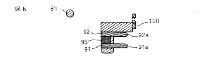
アクチュエータ80のL字状の平面形状の、シャフト81とは反対側の端部82には、アマチュア90が取り付けられている。アマチュア90は、鉄製の2つの板部材91,92を有し、これらが、アクチュエータ80の端部82に形成された穴83,84に嵌合して保持されることによって、互いに平行に、かつ鉛直に延びるように配置されている。板部材91,92は、アクチュエータ80の端部82の、シャフト81側の面から挿入され、図6の、アクチュエータ80の水平断面図に示すように、シャフト81と反対側の面から突出する突出部91a,92aを有している。アクチュエータ80は、突出部91a,92aの上方を覆うように水平に突出した突出部85を有している。板部材91,92の、突出部91a,92aと反対側の端部には、高さ方向の拡大部91b,92bが形成され、これらが、アクチュエータ80の穴83,84の不図示の拡大部に嵌ることによって、板部材91,92がアクチュエータ80に固定されている。
An
永久磁石95は、板部材91,92の拡大部91b,92bの間に挟み込まれ、また、アクチュエータ80の端部82の、シャフト81側の面に形成された溝に嵌合させられて保持されている。それにより、板部材91,92は永久磁石95の各極に接続されており、したがって、磁束経路を形成する板部材91,92の突出部91a,92a間には、一定の磁界が常に形成されている。
The
図7は、アマチュア90と鉄心40およびヨーク50の位置関係を説明するための断面図である。図7では、わかりやすくするために、アクチュエータ80やコイル31などの図示を省略している。また、図7では、簡略化のため、(a)と(b)とで、アマチュア90が平行移動しているように図示しているが、アクチュエータ80は旋回動作するので、アマチュア90も厳密には、(a)、(b)間で少し回転する。
FIG. 7 is a cross-sectional view for explaining the positional relationship between the
図7に示すように、アマチュア90は、その板部材91の突出部91aが、鉄心40の板部42とヨーク50の先端板部53の間に位置するように配置されている。したがって、永久磁石95によってアマチュア90の突出部91a,92aの間に発生する磁界と、コイル31によって鉄心40の板部42とヨーク50の先端板部53の間に発生する磁界との相互作用によって、アマチュア90に力が加わる。それによって、アマチュア90を介してアクチュエータ80に力が加わり、アクチュエータ80が旋回させられる。アマチュア90に加わる力の向きは、永久磁石95によってアマチュア90側に発生する磁界の向きに対して、コイル31によって発生する磁界の向きをコイル31への通電電流の向きを変化させることによって、図7の上下のいずれかとすることができる。
As shown in FIG. 7, the
アマチュア90は、図7での下方に力を加えることによって図7(a)に示すように、アマチュア90の突出部91aがヨーク50の先端板部53に当接し、突出部92aが鉄心41の板部42に当接する位置に移動させられる。すなわち、アクチュエータ80が、アマチュア90がこのような位置になるように旋回させられる。このように切り替えられると、アマチュア90の突出部91a,92aには、それらが当接する鉄心41の板部42およびヨーク50の先端板部53に付着する磁力が永久磁石95によって働く。したがって、アマチュア90は、コイル31への通電によって図7(a)に示す位置に切り替えた後、コイル31への通電を終了した場合、図7(a)の位置に保持される。
As shown in FIG. 7A, the amateur 90 applies a downward force in FIG. 7 so that the protruding
アマチュア90は、図7での上方に力を加えることによって図7(b)に示すように、アマチュア90の突出部91aが鉄心41の板部42に当接する位置に移動させられ、すなわち、アクチュエータ80が、対応する位置に旋回させられる。図7(a)の場合と同様に、アマチュア90は、コイル31への通電によって図7(b)に示す位置に切り替えた後、コイル31への通電を終了した場合、永久磁石95の発生する磁力によって、図7(b)の位置に保持される。
The amateur 90 is moved to a position where the projecting
アクチュエータ80には、その動作を、可動接点69a,69bに伝達する働きをするカード100がさらに取り付けられている。カード100は、アクチュエータ80の、アマチュア90の突出部91a,92aが突出している面の、シャフト81寄りの位置に形成された3つの凹部85〜87に、突起101〜103が嵌合させられてアクチュエータ80に取り付けられている。
The
カード100は、上端を水平に延びる上縁部105を有し、上縁部105の両端に、アクチュエータ80に嵌合する前述の突起102,103が形成されている。特に、突起102,103は、上縁部105の両端が、上縁部105の中央部に対して直角に延びるように屈曲した部分として形成されている。
The
上縁部105からは、2つの鉛直片106,107が下方に延びており、一方の鉛直片106の下端に、アクチュエータ80に嵌合する前述の突起101が形成されている。特に、突起101は、鉛直片106の下端が、鉛直片106の上部に対して直角に延びるように屈曲した部分として形成されている。
Two
図示していないが、鉛直片106,107の、互いに対面する側面間に、可動ばね64が挟み込まれて保持されている。鉛直片106,107の、互いに対面する側面には、凸部が形成され、鉛直片106の凸部と鉛直片107の凸部との間の、水平方向の距離が、可動ばね64の厚さより少し短くなっている。それによって、鉛直片106,107間に可動ばね64を、がたつきを生じることなく安定して保持することができるようになっている。
Although not shown, a
このように、アクチュエータ80に取り付けられたカード100によって可動ばね64が挟み込まれることによって、アマチュア90を介したアクチュエータ80の旋回に応じて、可動ばね64が変位させられる。それによって、可動ばね64に取り付けられた可動接点69a,69bが移動させられる。その結果、アマチュア90が、図7(a)に示す位置にある時には、可動接点69a,69bが固定接点73a,73bに当接させられて、バスバー端子60,70間が導通状態とされる。一方、アマチュア90が、図7(b)に示す位置にある時には、可動接点69a,69bが固定接点73a,73bから離隔し、バスバー端子60,70間が非導通状態とされる。
As described above, the
以上説明した本実施形態の電磁継電器では、アクチュエータ80が、旋回する部材として構成され、シャフト81によって形成される旋回軸線に垂直な面における形状が、一端に旋回軸線が位置する概ねL字形状になっている。この構成によれば、アクチュエータ80の、旋回軸線とは反対側の端部側にカード100を配置することによって、アクチュエータ80の大きさを最大限に利用して、カード100の、旋回軸線からの距離を比較的長くすることができる。したがって、アクチュエータ80の大きさおよび旋回角度を小さく抑えながら、カード100の移動量を大きくすることができる。
In the electromagnetic relay of the present embodiment described above, the
バスバー端子60,70間の電流を安定して遮断するために、可動接点69a,69bは、固定接点73a,73bから十分な量だけ離す必要があり、特に、大電流が流される場合、比較的大きく離すのが好ましい。したがって、カード100の移動量を十分に確保する必要があるが、本実施形態の構成によれば、上記のように、カード100の移動量を十分に確保するために必要な、アクチュエータ80の大きさおよび旋回角度が抑えられる。したがって、アクチュエータ80の配置スペース、およびアクチュエータ80を、旋回動作できるようにするために必要なスペースが低減され、それによって、電磁継電器1の小型化に寄与することができる。
In order to stably cut off the current between the
また、アマチュア90についても、アクチュエータ80の、旋回軸線とは反対側の端部側に配置することによって、アクチュエータ80の大きさを最大限に利用して、旋回軸線からの距離を比較的長くすることができる。アマチュア90を旋回軸線から遠い位置にすることによって、必要なトルクを得るためにアマチュア90に加える必要がある力を比較的小さくすることができる。それによって、コイル31や永久磁石95などの小型化が可能となり、電磁継電器1の小型化に寄与することができる。特に、大電流を流す場合、損失低減と加熱抑制のために抵抗を小さくするため、可動ばね64の断面積を大きくする必要があり、必要なトルクが大きくなりがちである。したがって、特に、大電流を流す場合に、アマチュア90を旋回軸線から遠くすることによって、電磁継電器1を小型化する効果を有効に得ることができる。
Further, the
また、特に、アマチュア90に永久磁石95を配置した有極継電器では、図7(a),(b)を参照して説明したような切り替え状態を安定して保持できるようにするために、アマチュア90の移動量を十分に確保するのが好ましい。この点でも、アクチュエータ80をL字状とした構成は、アマチュア90の移動量を十分に確保しながら、アクチュエータ80の大きさおよび旋回角度を小さく抑えることができるので好ましい。
In particular, in a polarized relay in which the
また、有極の構成とすることによって、コイル31の非通電時にも、アクチュエータ80は、永久磁石95の磁力によって鉄心40やヨーク50に付着させられて保持される。したがって、有極の構成には、旋回軸線部分で支持され、スライド式のアクチュエータなどに比べて、支持部位の少ない構成のアクチュエータ80であっても、安定性を確保できるという利点もある。
Further, by adopting a polar configuration, the
また、本実施形態の電磁継電器1では、ベース10に種々の部品が圧入されて保持されている。したがって、各部品を保持するための別途の部材が不要である。このことも、電磁継電器1の小型化に寄与する。
Moreover, in the
また、本実施形態では、可動ばね64と並列に平編線63を接続している。大電流を流す場合、損失の低減や加熱の抑制のため、電流経路の抵抗を低く抑える必要があるが、平編線63を用いることによって、抵抗を低く抑えながら、可動ばね64の断面積を小さくすることができる。その結果、可動ばね64を変位させるのに必要な力を軽減して、コイル31や永久磁石95などの小型化が可能となり、電磁継電器1の小型化に寄与することができる。
In this embodiment, the flat knitted
以上のようなことから、本実施形態の電磁継電器1では、従来よりも小型化、軽量化を図ることができる。具体的には、既存の有極電磁継電器の代表的な大きさは、735000mm3、重量は200gであるのに対して、本実施形態の構成によれば、大きさを約53000mm3、重量を120gとすることができた。
From the above, the
なお、上記の実施形態は本発明を例示するものであり、特許請求の範囲に規定する本発明の範囲内で種々の変更が可能である。例えば、上記の実施形態では、コイル端子35が4つ設けられ、一対が、バスバー端子60,70間を通電状態とするのに用いられ、他の一対が、バスバー端子60,70間を遮断するのに用いられる構成を示した。しかし、接続される回路に応じて、例えば、通電状態とする場合と、遮断状態とする場合とで、逆向きの電流信号を供給する回路が接続されるのであれば、コイル端子35は、2つとしてもよい。
In addition, said embodiment illustrates this invention, A various change is possible within the range of this invention prescribed | regulated to a claim. For example, in the above embodiment, four
また、上記の実施形態では、バスバー端子60,70にそれぞれ接続された信号端子65,75を電磁継電器1から引き出す構成とすることにより、信号端子65,75を利用して、バスバー端子60,70の導通状態をモニタリングできるようになっている。しかし、モニタリングの必要がなければ、信号端子65,75は省略してもよい。あるいは、外部回路で、バスバー端子60,70の接続部からモニタリング用の配線を引き出す構成とすることも考えられる。
In the above embodiment, the
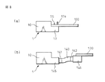
また、上記の実施形態では、ベース10に浅底部17が設けられ、その底面からコイル端子35および信号端子65,75が突出した構成を示した。この構成によれば、図8(a)に示すように、基板130が、浅底部17の底面に沿って位置するように、電磁継電器1を基板130に実装することができる。それにより、浅底部17の下方の空き領域を基板130の配置に利用して、全体として省スペース化を図ることができる。
Moreover, in said embodiment, the
この際、浅底部17の底面に形成された突起17d,17eを、例えば基板130に形成された穴に圧入するなどして、基板130と電磁継電器1を機械的に固定するのに利用することができる。この場合、前述のように、コイル端子35および信号端子65,75の先端に、圧入接続部35,65e,75eを設けた構成とすれば、基板130と電磁継電器1の機械的な固定をするのと一緒に、コイル端子35および信号端子65,75の電気的な接続も実行することができ、好都合である。しかし、コイル端子35および信号端子65,75は、はんだづけなどによって接続する構成としてもよいのはもちろんである。
At this time, the
変形例として、図8(b)に示すように、両端にコネクタ141,142を備えるハーネス140を用いて、電磁継電器1と基板130を接続する構成としてもよい。この場合、電磁継電器1には、ハーネス140のコネクタ141と接続されるコネクタ部145を設け、基板130には、ハーネス140のコネクタ142に接続されるコネクタ146を実装した構成とすることができる。
As a modified example, as shown in FIG. 8B, the
カード100に関しては、可動ばね64を挟み込む構造を有する例を示した。しかし、カード100は、可動接点69a,69bを、固定接点73a,73bとの接触位置と離隔位置とに動かすことができれば、可動ばね64にどのような形態で係合するものであってもよい。例えば、可動ばね64を、力を加えない状態では、可動接点69a,69bを固定接点73a,73bに接触した状態となるように付勢する構成とし、カード100は、可動接点69a,69bを離隔位置にする時にのみ、可動ばね64に当接する構成としてもよい。また、アクチュエータ80に可動ばね64との係合部を一体に形成してカード100を省略した構成としもよい。
Regarding the
1 電磁継電器
30 電磁石部
64 可動ばね
69a,69b 可動接点
73a,73b 固定接点
80 アクチュエータ
90 アマチュア
100 (可動ばねに係合する)カード
DESCRIPTION OF
Claims (9)
前記電磁石部の発生する磁界の作用によって移動させられるアマチュアが取り付けられたアクチュエータと、
前記アクチュエータに係合されて、前記アマチュアの移動に応じて変位させられる可動ばねと、
前記可動ばねに取り付けられた可動接点と、
前記可動接点が、前記アマチュアの移動に応じて、接触させられた状態と、離隔された状態とに切り替えられる固定接点と、
を有し、
前記アクチュエータは、前記アマチュアの移動に応じて旋回するように保持され、旋回軸線に垂直な面における形状がL字形状であり、該L字形状の一端に前記旋回軸線が位置し、前記L字形状の他端側に、前記アマチュア、および前記可動ばねとの係合部が設けられている、
電磁継電器。 An electromagnet part;
An actuator attached with an armature that is moved by the action of a magnetic field generated by the electromagnet part;
A movable spring engaged with the actuator and displaced in accordance with the movement of the amateur;
A movable contact attached to the movable spring;
The movable contact is switched between a contacted state and a separated state according to the movement of the amateur;
Have
The actuator is held so as to turn in accordance with the movement of the armature, the shape perpendicular to the turning axis is L-shaped, the turning axis is located at one end of the L-shape, and the L-shape On the other end side of the shape, an engaging portion with the amateur and the movable spring is provided,
Electromagnetic relay.
前記アマチュアは、永久磁石と、該永久磁石の各極にそれぞれ接続され磁束経路を形成する部材と、を有し、該磁束経路を形成する部材の一方が、前記鉄心と前記ヨークの、互いに間隔をおいて対面している部分の間に位置している、請求項1に記載の電磁継電器。 The electromagnet portion includes a bobbin around which a coil is wound, an iron core passing through the bobbin, and a yoke coupled to the iron core, the iron core is coupled to the yoke at one end, and the other end is It faces the yoke with a gap,
The armature has a permanent magnet and a member connected to each pole of the permanent magnet to form a magnetic flux path, and one of the members forming the magnetic flux path is spaced from the iron core and the yoke. The electromagnetic relay according to claim 1, wherein the electromagnetic relay is located between facing portions.
前記電磁石部は、コイルが巻かれた筒部と該筒部の端部に連結されたフランジを備えるボビンを有し、
前記バスバー端子と前記電磁石部は、前記ベースの同じ側面から該ベースに圧入されており、
前記バスバー端子の前記板部の、前記ベースに圧入される側と反対側の縁には、前記フランジの、前記ベースに圧入される側と反対側の縁に当接するように延びる押さえ部が形成されている、請求項3または4に記載の電磁継電器。 A plate portion to which the fixed contact is attached, and the plate portion further includes a bus bar terminal press-fitted into a groove formed in the base in a direction perpendicular to the plate thickness direction;
The electromagnet part has a bobbin including a cylindrical part wound with a coil and a flange connected to an end part of the cylindrical part,
The bus bar terminal and the electromagnet part are press-fitted into the base from the same side surface of the base,
On the edge of the plate portion of the bus bar terminal opposite to the side press-fitted into the base, a pressing portion is formed that extends to contact the edge of the flange opposite to the side press-fitted into the base. The electromagnetic relay according to claim 3 or 4, wherein:
Priority Applications (2)
| Application Number | Priority Date | Filing Date | Title |
|---|---|---|---|
| JP2008209264A JP5241375B2 (en) | 2008-08-15 | 2008-08-15 | Electromagnetic relay |
| US12/540,723 US8008999B2 (en) | 2008-08-15 | 2009-08-13 | Electromagnetic relay |
Applications Claiming Priority (1)
| Application Number | Priority Date | Filing Date | Title |
|---|---|---|---|
| JP2008209264A JP5241375B2 (en) | 2008-08-15 | 2008-08-15 | Electromagnetic relay |
Publications (2)
| Publication Number | Publication Date |
|---|---|
| JP2010044973A true JP2010044973A (en) | 2010-02-25 |
| JP5241375B2 JP5241375B2 (en) | 2013-07-17 |
Family
ID=41680922
Family Applications (1)
| Application Number | Title | Priority Date | Filing Date |
|---|---|---|---|
| JP2008209264A Active JP5241375B2 (en) | 2008-08-15 | 2008-08-15 | Electromagnetic relay |
Country Status (2)
| Country | Link |
|---|---|
| US (1) | US8008999B2 (en) |
| JP (1) | JP5241375B2 (en) |
Cited By (7)
| Publication number | Priority date | Publication date | Assignee | Title |
|---|---|---|---|---|
| CN102646521A (en) * | 2011-01-18 | 2012-08-22 | 泰科电子公司 | Electrical switching device |
| US20130307649A1 (en) * | 2009-11-16 | 2013-11-21 | Fujitsu Component Limited | Electromagnetic relay |
| KR101362901B1 (en) | 2013-11-20 | 2014-02-13 | 주식회사 와이엠텍 | Latch relay |
| US8659372B2 (en) | 2011-08-03 | 2014-02-25 | Fujitsu Component Limited | Electromagnetic relay |
| JP2014235823A (en) * | 2013-05-31 | 2014-12-15 | 東光東芝メーターシステムズ株式会社 | Latching relay |
| KR20180113453A (en) | 2017-04-06 | 2018-10-16 | 후지쯔 콤포넌트 가부시끼가이샤 | Electromagnetic relay |
| US10658141B2 (en) | 2016-10-05 | 2020-05-19 | Fujitsu Component Limited | Electromagnetic relay |
Families Citing this family (5)
| Publication number | Priority date | Publication date | Assignee | Title |
|---|---|---|---|---|
| DE102010017872B4 (en) * | 2010-04-21 | 2012-06-06 | Saia-Burgess Dresden Gmbh | Bistable small relay of high performance |
| CN103295847B (en) * | 2012-03-01 | 2016-12-07 | 德昌电机(深圳)有限公司 | Driving means and there is the relay of this driving means |
| JP6172387B2 (en) * | 2014-05-20 | 2017-08-02 | 富士電機機器制御株式会社 | Polarized DC electromagnet device and electromagnetic contactor using the same |
| CN106712440B (en) * | 2016-12-31 | 2019-07-26 | 武汉领普科技有限公司 | Power generator |
| JP7313168B2 (en) * | 2019-03-19 | 2023-07-24 | 富士通コンポーネント株式会社 | electromagnetic relay |
Citations (2)
| Publication number | Priority date | Publication date | Assignee | Title |
|---|---|---|---|---|
| JPS63134440U (en) * | 1987-02-24 | 1988-09-02 | ||
| JPH1145646A (en) * | 1997-07-28 | 1999-02-16 | Matsushita Electric Works Ltd | Relay |
Family Cites Families (12)
| Publication number | Priority date | Publication date | Assignee | Title |
|---|---|---|---|---|
| US4025884A (en) * | 1975-10-16 | 1977-05-24 | Guardian Electric Manufacturing Company | Relay construction |
| US4701734A (en) * | 1986-03-27 | 1987-10-20 | Niles Parts Co., Ltd. | Hinge type relay |
| EP0329138B1 (en) * | 1988-02-19 | 1993-06-23 | Siemens Aktiengesellschaft | Electromagnetic relay |
| WO1992017896A1 (en) * | 1991-03-28 | 1992-10-15 | Kilovac Corporation | Dc vacuum relay device with angular impact break mechanism |
| US5617067A (en) * | 1995-12-07 | 1997-04-01 | Eaton Corporation | Electromagnetic actuator having a low aspect ratio stator |
| JP3849197B2 (en) * | 1997-02-06 | 2006-11-22 | 松下電工株式会社 | relay |
| US6320485B1 (en) * | 1999-04-07 | 2001-11-20 | Klaus A. Gruner | Electromagnetic relay assembly with a linear motor |
| EP1154452B1 (en) * | 1999-09-28 | 2004-05-19 | Idec Izumi Corporation | Relay and method of manufacture thereof |
| JP4412819B2 (en) | 2000-06-23 | 2010-02-10 | 富士通コンポーネント株式会社 | Electromagnetic relay |
| JP2004172036A (en) | 2002-11-22 | 2004-06-17 | Omron Corp | Electromagnetic relay |
| JP4241606B2 (en) * | 2004-12-22 | 2009-03-18 | パナソニック電工株式会社 | Electromagnetic relay |
| DE102006007603B4 (en) * | 2006-02-18 | 2008-04-30 | Tyco Electronics Austria Gmbh | Relay with reduced leakage current |
-
2008
- 2008-08-15 JP JP2008209264A patent/JP5241375B2/en active Active
-
2009
- 2009-08-13 US US12/540,723 patent/US8008999B2/en active Active
Patent Citations (2)
| Publication number | Priority date | Publication date | Assignee | Title |
|---|---|---|---|---|
| JPS63134440U (en) * | 1987-02-24 | 1988-09-02 | ||
| JPH1145646A (en) * | 1997-07-28 | 1999-02-16 | Matsushita Electric Works Ltd | Relay |
Cited By (13)
| Publication number | Priority date | Publication date | Assignee | Title |
|---|---|---|---|---|
| US20130307649A1 (en) * | 2009-11-16 | 2013-11-21 | Fujitsu Component Limited | Electromagnetic relay |
| CN102646521A (en) * | 2011-01-18 | 2012-08-22 | 泰科电子公司 | Electrical switching device |
| US8659372B2 (en) | 2011-08-03 | 2014-02-25 | Fujitsu Component Limited | Electromagnetic relay |
| JP2014235823A (en) * | 2013-05-31 | 2014-12-15 | 東光東芝メーターシステムズ株式会社 | Latching relay |
| KR101362901B1 (en) | 2013-11-20 | 2014-02-13 | 주식회사 와이엠텍 | Latch relay |
| US10658141B2 (en) | 2016-10-05 | 2020-05-19 | Fujitsu Component Limited | Electromagnetic relay |
| JP2018181495A (en) * | 2017-04-06 | 2018-11-15 | 富士通コンポーネント株式会社 | Electromagnetic relay |
| KR20190134556A (en) | 2017-04-06 | 2019-12-04 | 후지쯔 콤포넌트 가부시끼가이샤 | Electromagnetic relay |
| KR20180113453A (en) | 2017-04-06 | 2018-10-16 | 후지쯔 콤포넌트 가부시끼가이샤 | Electromagnetic relay |
| EP3846196A1 (en) | 2017-04-06 | 2021-07-07 | Fujitsu Component Limited | Electromagnetic relay |
| JP7014524B2 (en) | 2017-04-06 | 2022-02-01 | 富士通コンポーネント株式会社 | Electromagnetic relay and control method of electromagnetic relay |
| US11328887B2 (en) | 2017-04-06 | 2022-05-10 | Fujitsu Component Limited | Electromagnetic relay |
| US11335527B2 (en) | 2017-04-06 | 2022-05-17 | Fujitsu Component Limited | Method for controlling electromagnetic relay |
Also Published As
| Publication number | Publication date |
|---|---|
| US8008999B2 (en) | 2011-08-30 |
| JP5241375B2 (en) | 2013-07-17 |
| US20100039195A1 (en) | 2010-02-18 |
Similar Documents
| Publication | Publication Date | Title |
|---|---|---|
| JP5241375B2 (en) | Electromagnetic relay | |
| JP5566172B2 (en) | Electromagnetic relay | |
| KR101742872B1 (en) | Electromagnetic relay | |
| JP6981732B2 (en) | Electromagnetic relay | |
| JP5923749B2 (en) | Contact device and electromagnetic relay using the contact device | |
| JP2013054846A (en) | Electromagnetic relay | |
| US10636603B2 (en) | Electromagnetic relay | |
| JP5821030B2 (en) | Electromagnetic relay | |
| JP2018181495A (en) | Electromagnetic relay | |
| JP5549642B2 (en) | relay | |
| US8050008B2 (en) | Relay device | |
| US20180096810A1 (en) | Electromagnetic relay | |
| JP4858508B2 (en) | Electromagnetic switchgear | |
| JP2013041764A (en) | Contact device and electromagnetic relay using contact device | |
| JP5448693B2 (en) | Electromagnetic relay | |
| CN111466007A (en) | Contact device and electromagnetic relay | |
| CN212365865U (en) | Contact device, electromagnetic relay, and device provided with electromagnetic relay | |
| JP7452113B2 (en) | electromagnetic relay | |
| JP5995078B2 (en) | Electromagnetic relay | |
| EP3611749B1 (en) | Contact device and electromagnetic relay | |
| JP6167372B2 (en) | Contact device and electromagnetic relay using the contact device | |
| JPH0723874Y2 (en) | Electromagnetic relay | |
| JP4412041B2 (en) | relay | |
| JP2012104360A (en) | Contact device | |
| JP2008159476A (en) | Relay |
Legal Events
| Date | Code | Title | Description |
|---|---|---|---|
| A621 | Written request for application examination |
Free format text: JAPANESE INTERMEDIATE CODE: A621 Effective date: 20110701 |
|
| A977 | Report on retrieval |
Free format text: JAPANESE INTERMEDIATE CODE: A971007 Effective date: 20121029 |
|
| A131 | Notification of reasons for refusal |
Free format text: JAPANESE INTERMEDIATE CODE: A131 Effective date: 20121106 |
|
| TRDD | Decision of grant or rejection written | ||
| A01 | Written decision to grant a patent or to grant a registration (utility model) |
Free format text: JAPANESE INTERMEDIATE CODE: A01 Effective date: 20130305 |
|
| A61 | First payment of annual fees (during grant procedure) |
Free format text: JAPANESE INTERMEDIATE CODE: A61 Effective date: 20130402 |
|
| FPAY | Renewal fee payment (event date is renewal date of database) |
Free format text: PAYMENT UNTIL: 20160412 Year of fee payment: 3 |
|
| R150 | Certificate of patent or registration of utility model |
Free format text: JAPANESE INTERMEDIATE CODE: R150 Ref document number: 5241375 Country of ref document: JP Free format text: JAPANESE INTERMEDIATE CODE: R150 |
|
| S531 | Written request for registration of change of domicile |
Free format text: JAPANESE INTERMEDIATE CODE: R313531 |
|
| R350 | Written notification of registration of transfer |
Free format text: JAPANESE INTERMEDIATE CODE: R350 |
|
| R250 | Receipt of annual fees |
Free format text: JAPANESE INTERMEDIATE CODE: R250 |
|
| R250 | Receipt of annual fees |
Free format text: JAPANESE INTERMEDIATE CODE: R250 |
|
| R250 | Receipt of annual fees |
Free format text: JAPANESE INTERMEDIATE CODE: R250 |
|
| R250 | Receipt of annual fees |
Free format text: JAPANESE INTERMEDIATE CODE: R250 |
|
| R250 | Receipt of annual fees |
Free format text: JAPANESE INTERMEDIATE CODE: R250 |
|
| R250 | Receipt of annual fees |
Free format text: JAPANESE INTERMEDIATE CODE: R250 |
|
| R250 | Receipt of annual fees |
Free format text: JAPANESE INTERMEDIATE CODE: R250 |
|
| R250 | Receipt of annual fees |
Free format text: JAPANESE INTERMEDIATE CODE: R250 |
|
| R250 | Receipt of annual fees |
Free format text: JAPANESE INTERMEDIATE CODE: R250 |