JP2010043978A - Enzyme electrode and manufacturing method thereof - Google Patents
Enzyme electrode and manufacturing method thereof Download PDFInfo
- Publication number
- JP2010043978A JP2010043978A JP2008208690A JP2008208690A JP2010043978A JP 2010043978 A JP2010043978 A JP 2010043978A JP 2008208690 A JP2008208690 A JP 2008208690A JP 2008208690 A JP2008208690 A JP 2008208690A JP 2010043978 A JP2010043978 A JP 2010043978A
- Authority
- JP
- Japan
- Prior art keywords
- enzyme
- membrane
- bound
- carbon
- electrode
- Prior art date
- Legal status (The legal status is an assumption and is not a legal conclusion. Google has not performed a legal analysis and makes no representation as to the accuracy of the status listed.)
- Granted
Links
Images


Classifications
-
- Y—GENERAL TAGGING OF NEW TECHNOLOGICAL DEVELOPMENTS; GENERAL TAGGING OF CROSS-SECTIONAL TECHNOLOGIES SPANNING OVER SEVERAL SECTIONS OF THE IPC; TECHNICAL SUBJECTS COVERED BY FORMER USPC CROSS-REFERENCE ART COLLECTIONS [XRACs] AND DIGESTS
- Y02—TECHNOLOGIES OR APPLICATIONS FOR MITIGATION OR ADAPTATION AGAINST CLIMATE CHANGE
- Y02E—REDUCTION OF GREENHOUSE GAS [GHG] EMISSIONS, RELATED TO ENERGY GENERATION, TRANSMISSION OR DISTRIBUTION
- Y02E60/00—Enabling technologies; Technologies with a potential or indirect contribution to GHG emissions mitigation
- Y02E60/30—Hydrogen technology
- Y02E60/50—Fuel cells
-
- Y—GENERAL TAGGING OF NEW TECHNOLOGICAL DEVELOPMENTS; GENERAL TAGGING OF CROSS-SECTIONAL TECHNOLOGIES SPANNING OVER SEVERAL SECTIONS OF THE IPC; TECHNICAL SUBJECTS COVERED BY FORMER USPC CROSS-REFERENCE ART COLLECTIONS [XRACs] AND DIGESTS
- Y02—TECHNOLOGIES OR APPLICATIONS FOR MITIGATION OR ADAPTATION AGAINST CLIMATE CHANGE
- Y02P—CLIMATE CHANGE MITIGATION TECHNOLOGIES IN THE PRODUCTION OR PROCESSING OF GOODS
- Y02P70/00—Climate change mitigation technologies in the production process for final industrial or consumer products
- Y02P70/50—Manufacturing or production processes characterised by the final manufactured product
Abstract
Description
この発明は、酵素電極およびその製造方法に係り、さらに詳しくは特定の処理工程を加えることによって従来の製造法では得られなかった高い割合で膜結合型酵素が炭素基材に結合している酵素電極およびその製造方法に関するものである。 The present invention relates to an enzyme electrode and a method for producing the same, and more specifically, an enzyme in which a membrane-bound enzyme is bound to a carbon substrate at a high rate that cannot be obtained by a conventional production method by adding a specific treatment step. The present invention relates to an electrode and a manufacturing method thereof.
従来、工業用および家庭用の動力源として、化石燃料の燃焼による熱エネルギーと電力エネルギーとが使用されてきた。そして、電力のほとんどは火力発電、原子力発電および水力発電により供給されている。しかし、火力発電は化石燃料の燃焼により電力を得るため二酸化炭素の大量排出という問題がある。また、各国の二酸化炭素の排出限度量を達成するためには火力発電への依存度をこれ以上高めることは困難である。さらに、化石燃料の枯渇および石油の値段の高騰という懸念もあり、火力発電による電力供給は今後徐々に減ることが予想される。 Conventionally, thermal energy and electric power energy by combustion of fossil fuels have been used as industrial and household power sources. And most of electric power is supplied by thermal power generation, nuclear power generation, and hydroelectric power generation. However, thermal power generation has a problem of mass emission of carbon dioxide because electric power is obtained by burning fossil fuel. In addition, it is difficult to increase the dependence on thermal power generation to achieve the carbon dioxide emission limit of each country. Furthermore, due to concerns about depletion of fossil fuels and rising oil prices, power supply from thermal power generation is expected to gradually decline in the future.
一方、原子力発電はスリーマイル島原子力発電所およびチェルノブィリ原子力発電所の事故後は長期間低迷していたものの、化石燃料による地球温暖化をもたらさない発電として最近は世界的に見直されており、産業構造を支える上では不可欠な発電方法となっている。しかし、ウラン鉱石の獲得競争が世界的に熾烈になっており、過度に原子力発電に期待することはできない。
水力発電は水の位置エネルギーを電気エネルギーに変換する方法であるから環境汚染の問題もなく、また潜在的な危険性も極めて低い発電方法である。しかし、発電量が降雨量などの自然条件に左右されやすく、需要に応じて発電量を制御するのは困難である。
On the other hand, although nuclear power generation has been sluggish for a long time after the accident at the Three Mile Island nuclear power plant and Chernobyl nuclear power plant, it has recently been reviewed globally as a power generation that does not cause global warming by fossil fuels. It is an indispensable power generation method for supporting the structure. However, the competition for uranium ore is fierce worldwide, and we cannot expect too much from nuclear power generation.
Hydroelectric power generation is a method for converting the potential energy of water into electrical energy, so there is no problem of environmental pollution and the potential danger is extremely low. However, the amount of power generation is easily affected by natural conditions such as rainfall, and it is difficult to control the amount of power generation according to demand.
このように大規模発電はそれぞれ問題を抱えており、このため、地球温暖化対策のために太陽電池や風力発電、あるいは波力発電など自然のエネルギーを電気エネルギーに転換する小規模発電が開発され実用段階にあるが、太陽電池はその製作にエネルギーとコストが掛かりしかもいずれの発電方法も季節や天候の影響を受けやすいという問題を抱えている。
また、燃料電池の開発研究が行われているが、電気エネルギー源として燃料電池を大規模に採用する場合には触媒として使用されている貴金属、例えば白金(Pt)の埋蔵量が少なく資源枯渇の問題とそれに伴い高価であること等の問題が指摘されている。このため、貴金属に代わる電極触媒の開発が進められている。
In this way, large-scale power generation has its own problems, and as a result, small-scale power generation that converts natural energy into electrical energy, such as solar cells, wind power generation, and wave power generation, has been developed to combat global warming. Although it is in the practical stage, solar cells have the problem that their production takes energy and cost, and any power generation method is easily affected by the season and weather.
In addition, research and development of fuel cells are being conducted. However, when fuel cells are used on a large scale as an electrical energy source, the reserves of precious metals used as catalysts, such as platinum (Pt), are small, and resource depletion has been reduced. Problems such as problems and associated high costs have been pointed out. For this reason, development of an electrode catalyst that replaces the noble metal is underway.
このような電極触媒として酸化還元酵素が注目されている。酸化還元型酵素は生物に由来する触媒であり、培養によって大量生産が可能なため白金のような貴金属と異なり無尽蔵である。
特に、水素酸化還元触媒であるヒドロゲナーゼを固定した酵素電極は、低コストの水素酸化電極又は水素発生リアクターとして将来有望であると考えられている。
このような酵素電極においては、効率よく基質から酵素を介して電子を伝達するためにカーボン電極基材に酵素を固定化することが必要である(特許文献1、非特許文献1〜2)。
As such an electrode catalyst, an oxidoreductase has attracted attention. A redox enzyme is a catalyst derived from living organisms, and can be mass-produced by culture, so it is inexhaustible unlike noble metals such as platinum.
In particular, an enzyme electrode on which hydrogenase, which is a hydrogen oxidation-reduction catalyst, is fixed is considered promising as a low-cost hydrogen oxidation electrode or hydrogen generation reactor.
In such an enzyme electrode, it is necessary to immobilize the enzyme on the carbon electrode substrate in order to efficiently transfer electrons from the substrate via the enzyme (
上記特許文献1には、電極上に特定の基質を酸化する酵素を備え、前記基質から前記酵素を介して前記電極に電子が伝達される酵素機能電極であって、前記酵素はチトクロームc部位を含む蛋白質からなり、チトクロームcのヘム鉄と隣接するアミノ酸は、疎水性アミノ酸等であり、疎水性の表面を持つか又は疎水性の官能基で修飾されたカーボン電極に固定されてなる酵素機能電極が記載されている。しかし前記の特許文献1では酵素の種類が限定されており、親水的な表面を持つ酵素については適用が困難である。
The above-mentioned
上記非特許文献1および2において、アームストロング(Armstrong)、F.A.(オックスフォード大学)らは、炭素電極のエッジ面に親水的な結合でヒドロゲナーゼの固定を行ったことが記載されているが、具体的に開示されている固定化されたヒドロゲナーゼの最大量は3x10⁻¹²mole/cm2である。
また、親水的な固定法では酵素の結合が不安定で、電解質溶液中で外れやすい(酸化電流測定中に徐々に外れて電流値が低下する)、酵素結合の方向性(配向性)の最適化が不十分であり、非特許文献1,2の方法では酵素がランダムな方向でカーボン電極に結合するため、ポリミキシン等の導電性ポリマーで覆っている。
In Non-Patent
In addition, in the hydrophilic fixation method, the enzyme binding is unstable, and it tends to come off in the electrolyte solution (the current value gradually drops during the oxidation current measurement), and the enzyme binding direction (orientation) is optimal. In the methods of
このように、従来公知の技術によれば、特定の種類の酵素を炭素電極基材に固定化することは可能であっても、酵素として親水的な表面を持つ自然に存在する膜結合型酵素を高い固定量、特に安定な結合、かつ酵素結合の方向性(配向性)を最適化して炭素電極基材に固定した酵素電極を得ることはできなかった。
従って、この発明の目的は、膜結合型酵素を高い固定量、特に安定な結合、かつ酵素結合の方向性(配向性)を最適化して炭素電極基材に固定した酵素電極およびその製造方法を提供することである。
As described above, according to a conventionally known technique, a specific type of enzyme can be immobilized on a carbon electrode substrate, but a naturally-occurring membrane-bound enzyme having a hydrophilic surface as an enzyme. It was not possible to obtain an enzyme electrode immobilized on a carbon electrode substrate by optimizing a high amount of fixation, particularly stable binding, and the directionality (orientation) of enzyme binding.
Accordingly, an object of the present invention is to provide an enzyme electrode in which a membrane-bound enzyme is immobilized on a carbon electrode substrate with a high fixed amount, particularly stable binding, and the direction (orientation) of enzyme binding optimized, and a method for producing the same. Is to provide.
この発明者らは、前記目的を達成するために鋭意研究を行った結果、カーボン電極基材に自然に存在する状態から界面活性剤によって細胞膜との結合を切り離して取り出した膜結合型酵素を単に炭素電極用基材と接触させたのでは、分離した膜結合型酵素が界面活性剤によって親水的な表面を持つため、炭素電極用基材への固定化が困難であることを見出し、さらに検討を行った結果この発明を完成した。
この発明は、膜結合型酵素が炭素基材に炭素基材1cm2当たり9x10⁻¹²mole以上の割合で固定されていることを特徴とする酵素電極に関する。
As a result of diligent research to achieve the above object, the present inventors simply obtained a membrane-bound enzyme that was separated from the cell membrane by a surfactant and removed from the state naturally existing on the carbon electrode substrate. When contacted with a carbon electrode substrate, the separated membrane-bound enzyme has a hydrophilic surface due to the surfactant, so it is difficult to immobilize it on the carbon electrode substrate. As a result, the present invention was completed.
The present invention relates to an enzyme electrode characterized in that a membrane-bound enzyme is immobilized on a carbon substrate at a rate of 9 × 10 −12 mole or more per 1 cm 2 of the carbon substrate.
また、この発明は、細胞膜と結合している膜結合型酵素を界面活性剤で処理して細胞膜を分離し、得られた界面活性剤が結合している膜結合型酵素から界面活性剤を除去して、膜結合型酵素を炭素基材に炭素基材1cm2当たり9x10⁻¹²mole以上の割合で固定することを特徴とする酵素電極の製造方法に関する。 In addition, this invention treats a membrane-bound enzyme bound to a cell membrane with a surfactant to separate the cell membrane, and removes the surfactant from the membrane-bound enzyme to which the obtained surfactant is bound. Then, the present invention relates to a method for producing an enzyme electrode, wherein a membrane-bound enzyme is immobilized on a carbon substrate at a rate of 9 × 10 −12 mole or more per 1 cm 2 of the carbon substrate.
この発明において、膜結合型酵素に炭素基材が固定されているということは、膜結合型酵素の疎水領域と炭素基材の疎水基とが化学的結合および/又は物理的な吸着を含む何らかの作用によって膜結合型酵素と炭素基材とが固定化されているということであって、後述の実施例の欄に詳細に記載される測定法により測定される膜結合型酵素が炭素基材に方向性を持って固定化されていることを意味する。
また、前記の膜結合型酵素の疎水領域とは細胞膜が結合していた親水性ではない部分を意味し、炭素基材の疎水基とは炭素基材の炭素原子を意味する。
In this invention, the carbon substrate is fixed to the membrane-bound enzyme means that the hydrophobic region of the membrane-bound enzyme and the hydrophobic group of the carbon substrate include chemical bonds and / or physical adsorption. This means that the membrane-bound enzyme and the carbon substrate are immobilized by the action, and the membrane-bound enzyme measured by the measurement method described in detail in the Examples section below is applied to the carbon substrate. It means that it is fixed with directionality.
In addition, the hydrophobic region of the membrane-bound enzyme means a non-hydrophilic portion to which the cell membrane is bound, and the hydrophobic group of the carbon substrate means a carbon atom of the carbon substrate.
この発明によれば、膜結合型酵素であっても高い固定量で炭素基材に固定した酵素電極を得ることができる。
また、この発明によれば、自然に存在する膜結合型酵素から高い固定量で炭素電極基材に固定した酵素電極を得ることができる。
この発明における膜結合型酵素の炭素基材への固定量は、後述の実施例の欄に詳細に説明される蛋白質総量を定量することで測定される固定前後の酵素溶液の酵素量の差から求められる算出値である。
According to this invention, it is possible to obtain an enzyme electrode fixed to a carbon substrate with a high fixed amount even if it is a membrane-bound enzyme.
Moreover, according to this invention, the enzyme electrode fixed to the carbon electrode base material with a high fixed amount from the membrane-bound enzyme which exists naturally can be obtained.
The amount of the membrane-bound enzyme immobilized on the carbon substrate in this invention is determined from the difference in the amount of enzyme in the enzyme solution before and after immobilization, which is measured by quantifying the total amount of protein described in detail in the Examples section below. This is the calculated value.
この発明における好適な態様を次に示す。
1)膜結合型酵素の疎水基と炭素基材の疎水基との直接結合によって、膜結合型酵素が炭素基材に固定化されている前記の酵素電極。
2)膜結合型酵素が炭素基材1cm2当たり1.6x10⁻¹¹mole以上の割合で固定されている前記の酵素電極。
3)膜結合型酵素が、ヒドロゲナーゼである前記の酵素電極。
4)界面活性剤除去剤処理によって界面活性剤が結合している膜結合型酵素から界面活性剤を除去する前記の製造方法。
5)膜結合型酵素が、ヒドロゲナーゼである前記の製造方法。
A preferred embodiment of the present invention will be described below.
1) The enzyme electrode as described above, wherein the membrane-bound enzyme is immobilized on the carbon substrate by direct bonding between the hydrophobic group of the membrane-bound enzyme and the hydrophobic group of the carbon substrate.
2) The enzyme electrode, wherein the membrane-bound enzyme is immobilized at a rate of 1.6 × 10 −11 mole or more per 1 cm 2 of the carbon substrate.
3) The enzyme electrode as described above, wherein the membrane-bound enzyme is a hydrogenase.
4) The production method described above, wherein the surfactant is removed from the membrane-bound enzyme to which the surfactant is bound by the surfactant removing agent treatment.
5) The production method described above, wherein the membrane-bound enzyme is hydrogenase.
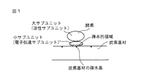
この発明の酵素電極について、この発明における膜結合型酵素が固定された炭素基材の1実施態様の部分模式図である図1、及びこの発明における膜結合型酵素が固定された炭素基材の他の実施態様の部分模式図である図2を用いて説明する。
図1において、膜結合型酵素の疎水基と炭素基材の疎水基との直接結合によって、膜結合型酵素が炭素基材に固定されている。この発明の酵素電極は、図1に示す膜結合型酵素が固定されたシート状の炭素基材を含んで構成される。
図2において、膜結合型酵素の疎水領域と炭素基材の疎水基との直接結合によって、膜結合型酵素が炭素基材に固定されている。この発明の酵素電極は、図2に示す膜結合型酵素が固定された粒子状の炭素基材を含んで構成される。
この発明の酵素電極は、図1に示すシート状の炭素電極又は図2に示す粒子状の炭素基材をそのまま又は前記の炭素基材をそれ自体公知の手段、例えばバインダーで固めてなるものである。
FIG. 1, which is a partial schematic view of one embodiment of a carbon substrate on which the membrane-bound enzyme is immobilized, and the carbon substrate on which the membrane-bound enzyme in the present invention is immobilized, are the enzyme electrode of the present invention. It demonstrates using FIG. 2 which is the partial schematic diagram of another embodiment.
In FIG. 1, the membrane-bound enzyme is immobilized on the carbon substrate by direct binding between the hydrophobic group of the membrane-bound enzyme and the hydrophobic group of the carbon substrate. The enzyme electrode of the present invention comprises a sheet-like carbon substrate on which the membrane-bound enzyme shown in FIG. 1 is fixed.
In FIG. 2, the membrane-bound enzyme is immobilized on the carbon substrate by direct binding between the hydrophobic region of the membrane-bound enzyme and the hydrophobic group of the carbon substrate. The enzyme electrode of the present invention includes a particulate carbon substrate on which the membrane-bound enzyme shown in FIG. 2 is fixed.
The enzyme electrode of the present invention is a sheet-like carbon electrode shown in FIG. 1 or a particulate carbon base material shown in FIG. 2 as it is or the carbon base material is solidified by means known per se, for example, a binder. is there.
この発明において、膜結合型酵素の疎水領域と炭素基材の疎水基との直接結合によって、膜結合型酵素が炭素基材に炭素基材1cm2当たり9x10⁻¹²mole以上、好適には1.6x10⁻¹¹mole以上の割合で固定されている。
前記の炭素基材としては、図1に示すシート状であってもよく又は図2に示す粒子状であってもよい。シート状カーボン基材として、グラッシーカーボン、カーボンナノチューブ、プラスチック成型カーボン、カーボンペーパー、カーボンフェルト、カーボンクロスなどを挙げることができる。また粒子状の炭素基材として、アセチレンブラック、バルカン、ケッチェンブラック、ブラックパール、メソ細孔カーボンなどを挙げることができる。
前記カーボン基材の寸法については特に制限はないが、好適には10μm〜1mm程度の厚みのシート状であってよく、また粒子状の炭素基材の粒径は通常は数十nm〜1μm程度であってよい。なお、膜結合型酵素の大きさは通常は数nmである。また、カーボン基材のBET比表面積は通常50〜2000m2/gであってよい。
In the present invention, by direct coupling with the hydrophobic group of the hydrophobic region and the carbon substrate membrane-bound enzymes, membrane-bound enzyme
As said carbon base material, the sheet form shown in FIG. 1 may be sufficient, or the particle form shown in FIG. 2 may be sufficient. Examples of the sheet-like carbon substrate include glassy carbon, carbon nanotubes, plastic molded carbon, carbon paper, carbon felt, carbon cloth, and the like. Examples of the particulate carbon substrate include acetylene black, vulcan, ketjen black, black pearl, and mesoporous carbon.
The size of the carbon base material is not particularly limited, but may preferably be a sheet having a thickness of about 10 μm to 1 mm, and the particle size of the particulate carbon base material is usually about several tens nm to 1 μm. It may be. The size of the membrane-bound enzyme is usually several nm. Moreover, the BET specific surface area of a carbon base material may be 50-2000 m < 2 > / g normally.
また、前記の膜結合型酵素の種類としては、例えばヒドロゲナーゼ、グルコースデヒドロゲナーゼ、アルコールデヒドロゲナーゼ、アルデヒドデヒドロゲナーゼが挙げられ、好適にはヒドロゲナーゼが挙げられる。これらの膜結合型酵素は1個の分子量が50000〜400000であり、ヒドロゲナーゼの分子量はおよそ100000である。
この発明においては、膜結合型酵素を用いることが必要であり、遊離型酵素ではこの発明の製造法を適用することができず、従って高い割合で酵素が固定した炭素基材を得ることができない。
Examples of the type of membrane-bound enzyme include hydrogenase, glucose dehydrogenase, alcohol dehydrogenase, and aldehyde dehydrogenase, with hydrogenase being preferred. These membrane-bound enzymes have a molecular weight of 50,000 to 400,000, and the molecular weight of hydrogenase is approximately 100,000.
In the present invention, it is necessary to use a membrane-bound enzyme, and the production method of the present invention cannot be applied to a free enzyme. Therefore, a carbon substrate on which an enzyme is immobilized at a high rate cannot be obtained. .
この発明における膜結合型酵素が前記の割合で固定されている炭素基材について、膜結合型酵素が固定されているこの発明の炭素基材の製造方法の実施態様の部分模式図である図3を参照しながら説明する。
図3において、工程(1)では、自然の状態では細胞膜に固定化されている膜結合型酵素を界面活性剤によって処理(界面活性剤処理)して、膜結合型酵素と細胞膜との結合を切り離す。次いで、工程(2)の精製工程において、分離装置を用いて細胞膜及び過剰の界面活性剤を除去し界面活性剤を必要最小限の濃度にして酵素を取り出す。次いで、工程(3)において膜結合型酵素の疎水領域に結合した界面活性剤を除去して、好適には結合した界面活性剤を除去すると同時に、次に示す工程(4)において、硫酸アンモニウムを添加して膜結合型酵素の疎水領域と炭素基材の疎水基(炭素)との直接結合を促すことによって膜結合型酵素を炭素基材に固定化して、膜結合型酵素が炭素基材に前記の炭素基材1cm2当たり9x10⁻¹²mole以上、好適には1cm2当たり1.6x10⁻¹¹mole以上の割合で固定した酵素電極を得ることができる。
FIG. 3 is a partial schematic view of an embodiment of the carbon substrate production method of the present invention in which the membrane-bound enzyme is immobilized with respect to the carbon substrate in which the membrane-bound enzyme in the present invention is immobilized at the above ratio. Will be described with reference to FIG.
In FIG. 3, in the step (1), the membrane-bound enzyme immobilized on the cell membrane in the natural state is treated with a surfactant (surfactant treatment) to bind the membrane-bound enzyme to the cell membrane. Separate. Next, in the purification step of step (2), the cell membrane and the excess surfactant are removed using a separation device, and the enzyme is taken out to a minimum concentration of the surfactant. Next, in step (3), the surfactant bound to the hydrophobic region of the membrane-bound enzyme is removed, and preferably the bound surfactant is removed. At the same time, ammonium sulfate is added in step (4) shown below. The membrane-bound enzyme is immobilized on the carbon substrate by encouraging the direct binding between the hydrophobic region of the membrane-bound enzyme and the hydrophobic group (carbon) of the carbon substrate.
前記の工程(1)において、自然の状態では細胞膜に固定化されている膜結合型酵素を界面活性剤、好適には非イオン性界面活性剤、例えば、Tween 20(商品名)、Nonidet P−40(商品名)、Triton X−100(商品名)、NP−40(商品名)、Igepal CA−630(商品名)、N−オクチル−グルコシド又は両性界面活性剤、例えば、CHAPS、3−ドデシル−ジメチルアンモニオ(dimethylammonio)−プロパン−1−スルホネート、ラウリルジメチルアミンオキシド)、好適には非イオン性界面活性剤を含む溶液によって処理して、膜結合型酵素を細胞膜から引き剥がすことによって、膜結合型酵素と細胞膜との結合を切り離す。
前記の界面活性剤の量は、非イオン性界面活性剤の場合、終濃度が0.1〜2質量%、特に0.2〜1質量%であることが好ましい。
In the step (1), a membrane-bound enzyme immobilized on a cell membrane in the natural state is converted into a surfactant, preferably a nonionic surfactant such as Tween 20 (trade name), Nonidet P- 40 (trade name), Triton X-100 (trade name), NP-40 (trade name), Igepal CA-630 (trade name), N-octyl-glucoside or an amphoteric surfactant such as CHAPS, 3-dodecyl By treating with a solution containing dimethylammonio-propane-1-sulfonate, lauryl dimethylamine oxide), preferably a nonionic surfactant, to release the membrane-bound enzyme from the cell membrane. Breaks the bond between the bound enzyme and the cell membrane.
As for the amount of the surfactant, in the case of a nonionic surfactant, the final concentration is preferably 0.1 to 2% by mass, particularly preferably 0.2 to 1% by mass.
前記の工程(1)において、界面活性剤処理する系は水溶液中であってよく、好適にはタンパク質である膜結合型酵素の保護剤として酵素の安定化剤(タンパク質分解酵素阻害剤ともいう)を含む水溶液であることが好ましい。この酵素の安定化剤としては、例えば、リン酸カリウムバッファー(pH7.0)、ジイソプロピルフルオロリン酸、ジチオビス(2−ニトロ安息香酸)、N−エチルマレイミド、p−クロロメルクリ安息香酸、p−ヒドロキシメルクリ安息香酸、フェニルメタンスルホニルフルオリド、N−トシル−L−リシルクロロメチルケトン、N−トシル−L−フェニルアラニルメチルケトン、ロイコペプチン、ペプスタチン等を挙げることができる。なお、前記の酵素の安定化剤は、例えば凝集防止剤としての作用が期待される。
前記の界面活性剤と酵素の安定化剤との割合(界面活性剤:酵素の安定化剤)は、質量比で1:10〜10:1、好適には5:1〜1:5であることが好ましい。
In the step (1), the surfactant treatment system may be in an aqueous solution, and preferably an enzyme stabilizer (also referred to as a proteolytic enzyme inhibitor) as a protective agent for a membrane-bound enzyme that is a protein. An aqueous solution containing is preferable. Examples of the enzyme stabilizer include potassium phosphate buffer (pH 7.0), diisopropylfluorophosphate, dithiobis (2-nitrobenzoic acid), N-ethylmaleimide, p-chloromercuribenzoic acid, p-hydroxy. Examples include mercuribenzoic acid, phenylmethanesulfonyl fluoride, N-tosyl-L-lysyl chloromethyl ketone, N-tosyl-L-phenylalanyl methyl ketone, leucopeptin, and pepstatin. The enzyme stabilizer is expected to act as an anti-aggregation agent, for example.
The ratio of the surfactant to the enzyme stabilizer (surfactant: enzyme stabilizer) is from 1:10 to 10: 1, preferably from 5: 1 to 1: 5 by mass ratio. It is preferable.
前記の界面活性剤処理は嫌気的雰囲気下に、0〜30℃、好適には0〜25℃の範囲内の温度で10分間〜10時間、攪拌下に行うことが好ましい。
前記の界面活性剤処理に用いる反応容器としては、攪拌装置を備えたタンパク質の処理に一般に用いられる反応容器を用いることができる。また、取り扱い時の安全性を考慮し、密閉可能な容器を用いることが好ましい。
この発明の方法においては、前記の工程(1)に続いて工程(2)の精製工程が行われるが、膜結合型酵素が耐熱性を有している場合には工程(2)の精製工程の前処理として加熱処理を加えることが好ましい。この加熱処理によって酵素から細胞膜(細胞壁ともいう)の除去、つまり酵素の可溶化と、次の工程の簡素化(単純化、例えば使用するカラムの本数の低減など)とが可能となる。前記の加熱処理は50℃以上80℃以下、特に50℃以上70℃以下の温度で5〜30分間行うことが好ましい。
前記の加熱処理を行った後、一旦液の温度を0〜30℃、特に0〜25℃の範囲に冷却した後、次の工程(2)を行うことが好ましい。
The surfactant treatment is preferably performed under stirring in an anaerobic atmosphere at a temperature in the range of 0 to 30 ° C., preferably 0 to 25 ° C. for 10 minutes to 10 hours.
As the reaction vessel used for the surfactant treatment, a reaction vessel generally used for protein treatment equipped with a stirrer can be used. In consideration of safety during handling, it is preferable to use a sealable container.
In the method of the present invention, the purification step of the step (2) is performed following the above step (1). However, when the membrane-bound enzyme has heat resistance, the purification step of the step (2) Heat treatment is preferably added as a pretreatment. This heat treatment makes it possible to remove cell membranes (also referred to as cell walls) from the enzyme, that is, solubilize the enzyme, and simplify the next step (simplification, for example, reducing the number of columns used). The heat treatment is preferably performed at a temperature of 50 ° C. to 80 ° C., particularly 50 ° C. to 70 ° C. for 5 to 30 minutes.
After performing the above heat treatment, it is preferable that the temperature of the liquid is once cooled to 0 to 30 ° C., particularly 0 to 25 ° C., and then the next step (2) is performed.
前記の工程(2)の精製工程において、それ自体公知の精製方法、例えば遠心分離、透析法、ゲルろ過法、樹脂吸着法の1種又は2種以上の組合せにより、またそれ自体公知の分離装置、例えば、高速遠心分離機、カラム、カートリッジ、ディスク、フィルター又はキャピラリーのいずれかの形態、好適には高速遠心分離機とカラムとの組み合わせを用いて細胞膜及び過剰の界面活性剤を除去して、膜結合型酵素を取り出す。
前記のカラムを用いた分離精製法として、イオン交換クロマトグラフィー、ゲルろ過クロマトグラフィー、疎水性クロマトグラフィー、アフィニティークロマトグラフィー、逆相クロマトグラフィー、ヒドロキシアパタイトなどによる吸着クロマトグラフィーなどを適宜組み合わせて又はこれらのいずれかの単独で、具体例としてSP−セファロース高流速(FF)クロマトグラフィー、Q−セファロース高速(HP)クロマトグラフィー、ブチル疎水性相互作用クロマトグラフィー(HIC)、SP−セファロースHPクロマトグラフィー、トーヨーパールHW50、ブルー−トーヨーパール650ML、オクチル−セファロースファーストフロー、ヒドロキシアパタイト、スーパーデックス200などを挙げることができる。
In the purification step of the above step (2), a known purification method such as centrifugation, dialysis method, gel filtration method, one or a combination of two or more of resin adsorption methods, and a separation device known per se Removing cell membranes and excess detergent using, for example, any form of high speed centrifuge, column, cartridge, disk, filter or capillary, preferably a combination of high speed centrifuge and column, Remove the membrane-bound enzyme.
As a separation and purification method using the above-mentioned column, ion exchange chromatography, gel filtration chromatography, hydrophobic chromatography, affinity chromatography, reverse phase chromatography, adsorption chromatography using hydroxyapatite, or the like may be used in combination as appropriate. Any one of them, SP-Sepharose high flow rate (FF) chromatography, Q-Sepharose high-speed (HP) chromatography, butyl hydrophobic interaction chromatography (HIC), SP-Sepharose HP chromatography, Toyopearl HW50, Blue-Toyopearl 650ML, Octyl-Sepharose Fast Flow, Hydroxyapatite, Superdex 200, etc. can be mentioned.
前記のカラムクロマトグラフィーを用いる分離精製の際に、膜結合型酵素を含む系を中性又は弱酸性のバッファーを用いて、膜結合型酵素をカラムに負荷且つカラムから溶出させることが好ましい。
そして、前記の界面活性剤の除去の程度は、一般的にタンパク質の測定に適用される電気泳動により単一バンドまで精製されることが好ましい。取り出された膜結合型酵素は嫌気的雰囲気、好適にはアルゴン雰囲気で保存することが好ましい。
前記の精製工程で取り出された膜結合型酵素は、疎水領域に界面活性剤が結合しており全体として親水性である。
During the separation and purification using the column chromatography, it is preferable that the membrane-bound enzyme is loaded onto the column and eluted from the column using a neutral or weakly acidic buffer for the system containing the membrane-bound enzyme.
The degree of removal of the surfactant is preferably purified to a single band by electrophoresis generally applied to protein measurement. The extracted membrane-bound enzyme is preferably stored in an anaerobic atmosphere, preferably an argon atmosphere.
The membrane-bound enzyme extracted in the purification step is hydrophilic as a whole because a surfactant is bound to the hydrophobic region.
次の工程(3)において、膜結合型酵素の疎水領域に結合した界面活性剤を除去し、好適には結合している界面活性剤を除去すると同時に、次に示す工程(4)において膜結合型酵素の疎水領域と炭素基材の疎水基(炭素)との直接結合によって固定化する。
前記の工程(3)において、膜結合型酵素の疎水領域に結合している界面活性剤を除去する際に、先ず工程(2)で取り出された疎水領域に界面活性剤が結合した膜結合型酵素は水溶液中に溶解させることが好ましい。
前記の水溶液中には、膜結合型酵素が1〜100単位/mL、特に5〜50単位/mLの割合で含まれていることが好ましい。
In the next step (3), the surfactant bound to the hydrophobic region of the membrane-bound enzyme is removed, and preferably the bound surfactant is removed. Immobilization is performed by direct bonding between the hydrophobic region of the type enzyme and the hydrophobic group (carbon) of the carbon substrate.
In the step (3), when removing the surfactant bound to the hydrophobic region of the membrane-bound enzyme, the membrane-bound type in which the surfactant is first bound to the hydrophobic region taken out in the step (2) The enzyme is preferably dissolved in an aqueous solution.
It is preferable that the membrane-bound enzyme is contained in the aqueous solution at a rate of 1 to 100 units / mL, particularly 5 to 50 units / mL.
前記の膜結合型酵素の疎水領域に結合している界面活性剤を除去する方法として、例えば予め膜結合型酵素を固定化する炭素基材の表面に界面活性剤除去機能を有する処理剤を適用してもよい。 As a method for removing the surfactant bound to the hydrophobic region of the membrane-bound enzyme, for example, a treatment agent having a surfactant-removing function is applied to the surface of the carbon substrate on which the membrane-bound enzyme is immobilized in advance. May be.
前記の工程(3)において、好適には嫌気雰囲気下に界面活性剤が結合した膜結合型酵素を含む水溶液に界面活性剤除去機能を有する処理剤を存在させて、界面活性剤を除去して時間が余り経過しないうちに炭素基材と界面活性剤が除去された膜結合型酵素を接触させることが好ましい。これは、界面活性剤を除去して多くの時間経過後に炭素基材と界面活性剤が除去された膜結合型酵素とを接触させても、界面活性剤が除去された膜結合型酵素の疎水領域と他の膜結合型酵素の疎水領域とが結合するため酵素間の結合が生じ、膜結合型酵素の炭素基材への固定化の程度が減少するからである。 In the above step (3), a surfactant having a function of removing a surfactant is preferably present in an aqueous solution containing a membrane-bound enzyme bound with a surfactant in an anaerobic atmosphere to remove the surfactant. It is preferable to bring the carbon substrate and the membrane-bound enzyme from which the surfactant has been removed into contact with each other before the time has passed. This is because the hydrophobicity of the membrane-bound enzyme from which the surfactant has been removed even when the surfactant is removed and the membrane-bound enzyme from which the surfactant has been removed is brought into contact after a long time has passed. This is because the binding between the region and the hydrophobic region of another membrane-bound enzyme results in binding between the enzymes, and the degree of immobilization of the membrane-bound enzyme on the carbon substrate is reduced.
この酵素間の結合を避けるために、面活性剤が結合した膜結合型酵素を含む酵素水溶液に界面活性剤除去機能を有する処理剤を添加する前、又は添加と同時又は添加の直後に炭素基材を酵素水溶液中に浸漬するか、又は炭素基材に界面活性剤除去機能を有する処理剤を添加した直後の膜結合型酵素水溶液を塗布してもよい。あるいは、予め炭素基材の表面に界面活性剤除去機能を有する処理剤を付着させておき、この界面活性剤除去機能を有する処理剤を付着した炭素基材を酵素溶液中に浸漬するか又は界面活性剤除去機能を有する処理剤を付着した炭素基材に膜結合型酵素水溶液を塗布してもよい。
前記の界面活性剤除去機能を有する処理剤としての硫酸アンモニウムの量は、酵素液1mLあたり0.1〜1.5M(モル濃度)、特に0.1〜0.5Mであることが好ましい。
また、前記の水溶液中には膜結合型酵素の疎水的領域に結合した界面活性剤の除去を促す等の目的でアルコール、例えばエタノールを加えても良い。
この発明の方法において、前記の工程(3)および工程(4)は0℃以上50℃以下、特に0〜30℃の温度で、合計で10分間〜10時間、特に1〜10時間程度行うことが好ましい。
In order to avoid the binding between the enzymes, the carbon group is added before, simultaneously with, or immediately after the addition of the treatment agent having the surfactant removing function to the aqueous enzyme solution containing the membrane-bound enzyme to which the surfactant is bound. The material may be immersed in an aqueous enzyme solution, or a membrane-bound enzyme aqueous solution immediately after adding a treatment agent having a surfactant removing function to a carbon substrate may be applied. Alternatively, a treatment agent having a surfactant removing function is previously attached to the surface of the carbon substrate, and the carbon substrate to which the treatment agent having the surfactant removing function is attached is immersed in the enzyme solution or the interface. A membrane-bound enzyme aqueous solution may be applied to a carbon substrate to which a treatment agent having an activator removing function is attached.
The amount of ammonium sulfate as the treatment agent having the surfactant removing function is preferably 0.1 to 1.5 M (molar concentration), particularly 0.1 to 0.5 M, per mL of the enzyme solution.
In addition, an alcohol such as ethanol may be added to the aqueous solution for the purpose of promoting the removal of the surfactant bound to the hydrophobic region of the membrane-bound enzyme.
In the method of the present invention, the steps (3) and (4) are performed at a temperature of 0 ° C. or higher and 50 ° C. or lower, particularly 0 to 30 ° C., for a total of 10 minutes to 10 hours, particularly about 1 to 10 hours. Is preferred.
前記の工程(1)〜(4)の工程により、従来の技術では達成が不可能であった膜結合型酵素が炭素基材に炭素基材1cm2当たり9x10⁻¹²mole以上、好適には1.6x10⁻¹¹mole以上という高い割合で固定されている炭素基材を得ることができ、この高い割合での固定量は前記の非特許文献1〜2に記載されているヒドロゲナーゼの最大固定量:3x10⁻¹²mole/cm2と比べて大幅に改善されている。
According to the steps (1) to (4), the membrane-bound enzyme, which could not be achieved by the conventional technique, is 9 × 10 −12 mole or more, preferably 1 per 1 cm 2 of the carbon substrate. A carbon substrate fixed at a high rate of 6 × 10 −11 mole or more can be obtained, and the fixed amount at this high rate is the maximum fixed amount of hydrogenase described in
さらに、この発明によれば、炭素基材との電子の授受に好ましい方向性を持って炭素基材への前記酵素の固定化が可能である。
この前記酵素の方向性を持った炭素基材への固定化の理論的な根拠は不明であるが、膜結合型酵素の疎水領域と炭素基材の疎水基との直接的な結合によってもたらされるものと考えられる。この方向性を持った炭素基材への前記酵素の固定化は、例えば図2に示すように、粒子状の炭素基材の多数の疎水基に多数の膜結合型酵素の疎水領域が結合していることによって、後述の実施例の欄に詳細に説明される酵素が固定化された炭素の重水素置換活性が溶液中の遊離酵素の重水素置換活性に比較して、好適には遊離酵素の12%以下、特に3%以下の重水素置換活性を示すことから理解される。
Furthermore, according to the present invention, the enzyme can be immobilized on the carbon base material with a preferable direction for the exchange of electrons with the carbon base material.
The theoretical basis for the immobilization of the enzyme on a carbon substrate with directionality is unknown, but it is brought about by the direct binding between the hydrophobic region of the membrane-bound enzyme and the hydrophobic group of the carbon substrate. It is considered a thing. For example, as shown in FIG. 2, the immobilization of the enzyme on a carbon substrate having this orientation is performed by binding hydrophobic regions of many membrane-bound enzymes to many hydrophobic groups of a particulate carbon substrate. Therefore, the deuterium displacement activity of the carbon on which the enzyme described in detail in the Examples section described below is immobilized is preferably a free enzyme compared to the deuterium displacement activity of the free enzyme in the solution. Of deuterium substitution activity of 12% or less, particularly 3% or less.
この発明の酵素電極は、前記のシート状の炭素電極又は粒子状の炭素基材をそのまま又は前記の炭素基材をそれ自体公知の手段、例えばバインダーで固めてなるものである。
従って、この発明の酵素電極は、膜結合型酵素が炭素基材に炭素基材1cm2当たり9x10⁻¹²mole以上、好適には1.6x10⁻¹¹mole以上の割合で固定されている。
The enzyme electrode of the present invention is obtained by solidifying the sheet-like carbon electrode or the particulate carbon substrate as it is or by a means known per se, for example, a binder.
Therefore, in the enzyme electrode of the present invention, the membrane-bound enzyme is immobilized on the carbon substrate at a rate of 9 × 10 −12 mole or more, preferably 1.6 × 10 −11 mole or more per 1 cm 2 of the carbon substrate.
この発明によって得られる酵素電極は、高い割合で膜結合型酵素が炭素基材に固定化されており、バイオ燃料電池の酵素電極として又はバイオセンサの用途に用いられ得る。例えば、この発明の酵素電極は、膜結合型酵素がヒドロゲナーゼである場合、水素還元反応に対する触媒活性を有していることからアノード(燃料極)の電極として用いることができる。また、この発明の酵素電極は、炭素基材と膜結合型酵素とが好ましい方向性を持って直接結合しているので電子伝達の効率が高いことが期待され、さらに電子伝達の効率を高めるために電子伝達を媒体する電子伝達メディエータ、例えばメチルビオロゲン、ベンジルビオロゲンなどを用いてもよい。 In the enzyme electrode obtained by the present invention, a membrane-bound enzyme is immobilized on a carbon substrate at a high rate, and can be used as an enzyme electrode of a biofuel cell or for a biosensor. For example, when the membrane-bound enzyme is a hydrogenase, the enzyme electrode of the present invention can be used as an anode (fuel electrode) electrode because it has a catalytic activity for a hydrogen reduction reaction. In addition, the enzyme electrode of the present invention is expected to have high electron transfer efficiency because the carbon substrate and the membrane-bound enzyme are directly bonded with a preferred direction, and further to increase the electron transfer efficiency. Alternatively, an electron transfer mediator that mediates electron transfer, such as methyl viologen or benzyl viologen, may be used.
以下に、実施例によってこの発明をさらに詳細に説明するが、この発明はこれらの例によって何ら限定されるものではない。 Hereinafter, the present invention will be described in more detail by way of examples, but the present invention is not limited to these examples.
以下の各例において、炭素基材に固定されている膜結合型酵素の固定量は、以下の方法によって酵素溶液中の蛋白質濃度を測定することによって算出した。 In each of the following examples, the amount of the membrane-bound enzyme immobilized on the carbon substrate was calculated by measuring the protein concentration in the enzyme solution by the following method.
アノード側の電解液としては、酵素溶液、リン酸緩衝液(pH6.4)の混合液を用いた。固定酵素の活性を正確に評価するため、メディエータであるベンジルビオロゲンを20mM濃度になるように添加した。電解液には、測定前にH2ガスで十分にバブリングを行い、ベンジルビオロゲン(BV)還元活性を測定した。測定条件を以下に示す。
温度 60℃
pH 6.4
酵素溶液 2mL
メディエータ ベンジルビオロゲン
As the electrolyte solution on the anode side, a mixed solution of an enzyme solution and a phosphate buffer (pH 6.4) was used. In order to accurately evaluate the activity of the immobilized enzyme, benzyl viologen as a mediator was added to a concentration of 20 mM. Before the measurement, the electrolyte solution was sufficiently bubbled with H 2 gas to measure benzyl viologen (BV) reducing activity. The measurement conditions are shown below.
60 ° C
pH 6.4
Enzyme solution 2mL
Mediator benzyl viologen
また、以下の実施例において、膜結合型酵素が炭素基材に固定化されている方向性を測定するための遊離酵素とカーボン粉末に固定した酵素の重水素置換活性の算出法を以下に示す。
膜結合型酵素が炭素基材に固定化されている方向性の測定
(1)ヒドロゲナーゼの活性化
酵素1mLに対して、嫌気チェンバー内にて50mMのナトリウムジチオナイトを40μL添加し(終濃度:約2mM)、1時間以上室温で活性化を行った。その後、バイアル瓶を密栓し、Arガスで置換した。
(2)活性測定
以下の反応系で30℃にて測定した。50mMのナトリウムジチオナイトは嫌気チェンバー内でバイアル瓶にて調製し、密栓した。気相をArガスで置換して使用した。
50mM MESバッファー(pH5.5) 3mL
50mM ナトリウムジチオナイト(20mM トリス−HCl、pH7.0) 10μL
酵素液 10〜150μL
In the following examples, the calculation method of the deuterium displacement activity of the free enzyme and the enzyme immobilized on the carbon powder for measuring the directionality in which the membrane-bound enzyme is immobilized on the carbon substrate is shown below. .
Measurement of directionality in which membrane-bound enzyme is immobilized on carbon substrate (1) Activation of hydrogenase To 1 mL of enzyme, 40 μL of 50 mM sodium dithionite is added in an anaerobic chamber (final concentration: about 2 mM) Activation was performed at room temperature for 1 hour or more. The vial was then sealed and replaced with Ar gas.
(2) Activity measurement It measured at 30 degreeC with the following reaction systems. 50 mM sodium dithionite was prepared in a vial in an anaerobic chamber and sealed. The gas phase was replaced with Ar gas.
50 mM MES buffer (pH 5.5) 3 mL
50 mM sodium dithionite (20 mM Tris-HCl, pH 7.0) 10 μL
Enzyme solution 10-150 μL
反応液中の溶存ガスはガラス製反応槽下部の疎水性テフロン(登録商標)膜(アドバンテック社、PTFEメンブレンフィルター T020A025、孔径0.20μm、直径25mm)を通してターボ分子ポンプ、ロータリーポンプによってによって吸引され、液体窒素で冷却した水蒸気トラップ管を経て四重極質量分析計の分析チャンバーに導入された。このようにして、反応液中の溶存ガス濃度を分子量ごとに経時的に測定し、分圧としてPa単位で測定した。なお、反応槽の外周に温度調節水を循環させることにより、反応系を30℃に保った。 The dissolved gas in the reaction solution is sucked by a turbo molecular pump and a rotary pump through a hydrophobic Teflon (registered trademark) membrane (Advantech, PTFE membrane filter T020A025, pore size 0.20 μm, diameter 25 mm) at the bottom of the glass reaction tank, It was introduced into the analysis chamber of the quadrupole mass spectrometer via a water vapor trap tube cooled with liquid nitrogen. In this way, the dissolved gas concentration in the reaction solution was measured over time for each molecular weight, and the partial pressure was measured in units of Pa. In addition, the reaction system was kept at 30 ° C. by circulating temperature-controlled water around the outer periphery of the reaction tank.
測定手順はまず、反応槽のガラス内筒にバッファーを入れ、軽水素ガスをバブリングして飽和化し、その飽和分圧を測定した。次に重水素ガスをバブリングして飽和化させた後、ナトリウムジチオナイトと酵素液をシリンジで添加して重水素置換反応をスタートさせた。反応によって単位時間当たりに生じた軽水素の量を求め、重水素置換活性を算出した。
活性の算出は、30℃における軽水素の飽和濃度を0.66μmole/mLとして、測定値の単位Paあたりの軽水素濃度を求めた。それをもとに、1分間あたりの反応によって生じた軽水素の量を濃度(μmole/mL)に換算し、さらに酵素液1mLあたりに換算して活性値とした。
The measurement procedure was as follows. First, a buffer was placed in the glass inner cylinder of the reaction vessel, light hydrogen gas was bubbled and saturated, and the saturation partial pressure was measured. Next, after deuterium gas was bubbled and saturated, sodium dithionite and an enzyme solution were added with a syringe to start the deuterium substitution reaction. The amount of light hydrogen generated per unit time by the reaction was determined, and the deuterium displacement activity was calculated.
The activity was calculated by determining the light hydrogen concentration per unit Pa of the measured value, assuming that the saturation concentration of light hydrogen at 30 ° C. was 0.66 μmole / mL. Based on this, the amount of light hydrogen generated by the reaction per minute was converted to a concentration (μmole / mL), and further converted to an activity value per 1 mL of enzyme solution.
実施例1
1.細胞膜区分の調製
Example 1
1. Preparation of cell membrane compartment

の培養は水素:酸素:炭酸ガス(75:15:10)の混合ガスを供給し、37℃にて独立栄養的に行った。培養後の湿重量菌体1gは5mlの20mMリン酸緩衝液(pH7.0)に懸濁し、60W(output6、約5分x2回)で超音波破砕した後、遠心分離・超遠心分離によって細胞膜を得た。 Incubation was performed autotrophically at 37 ° C. by supplying a mixed gas of hydrogen: oxygen: carbon dioxide (75:15:10). 1 g of wet-wet cells after culturing is suspended in 5 ml of 20 mM phosphate buffer (pH 7.0), sonicated at 60 W (output 6, approximately 5 minutes × 2 times), and then subjected to centrifugation and ultracentrifugation. Got.
2.細胞膜を分離した膜結合型酵素の調製
膜画分に界面活性剤としての1%Triton X−100と、凝集防止の目的で酵素の安定化剤としての20mMのリン酸カリウムバッファー(pH7.0)を)とを1:1の割合で混合し、Triton X−100の終濃度を0.5質量%とした。Ar気相下にて4℃、1時間穏やかに攪拌することによってヒドロゲナーゼの可溶化を行った。その後、加熱処理によって熱に不安定なタンパク質を変性除去して、熱に安定なヒドロゲナーゼの可溶化(細胞壁(膜)除去)の効率化と精製方法の単純化を可能とした。加熱処理はサンプルの温度が60℃に達した後、15分間行った。その後、氷上にて1時間以上放置してから20000xg、4℃、20分間の高速遠心分離によって沈殿を除去した上澄をQ−Sepharose High Performanceカラムに供した。精製用バッファーは20mMのBis−Tris(pH6.8)、10%グリセロール、0.025% Triton X−100を使用し、塩化ナトリウムの濃度勾配によりヒドロゲナーゼの溶出を行った。170mM程度の塩化ナトリウム濃度で溶出された活性画分をヒドロキシアパタイトによるカラムクロマトグラフィーに供し、1〜400mMリン酸カリウムバッファー(pH6.8)の濃度勾配により溶出を行った。なお、バッファーは10%グリセロール、0.025% Triton X−100を添加して使用した。100mM前後のリン酸濃度で溶出されたヒドロゲナーゼ活性画分はAmicon Ultra−15を用いて濃縮し、Superdex−200のゲルろ過に供することで、電気泳動上単一バンドまで精製した。バッファーは20mMリン酸カリウムバッファー(pH7.0)、10%グリセロール、0.2M塩化ナトリウム、0.025%Triton X−100を使用した。精製酵素はバイアルびんに分注し、気相をアルゴンとして室温にて保存した。この酵素はグリセロールを添加することによって酵素活性が安定化されたため、各精製段階で使用したバッファーには10%グリセロールを添加した。また、バッファーはアルゴン置換により嫌気的に使用した。
2. Preparation of membrane-bound enzyme from which cell membrane was separated 1% Triton X-100 as a surfactant in the membrane fraction and 20 mM potassium phosphate buffer (pH 7.0) as an enzyme stabilizer for the purpose of preventing aggregation Were mixed at a ratio of 1: 1 so that the final concentration of Triton X-100 was 0.5 mass%. Hydrogenase was solubilized by gently stirring at 4 ° C. for 1 hour in an Ar gas phase. Thereafter, heat-labile proteins were denatured and removed by heat treatment, so that heat-stable hydrogenase solubilization (cell wall (membrane) removal) could be made more efficient and the purification method simplified. The heat treatment was performed for 15 minutes after the temperature of the sample reached 60 ° C. Then, after leaving it on ice for 1 hour or more, the supernatant from which the precipitate was removed by high-speed centrifugation at 20000 × g and 4 ° C. for 20 minutes was applied to a Q-Sepharose High Performance column. As a purification buffer, 20 mM Bis-Tris (pH 6.8), 10% glycerol, 0.025% Triton X-100 was used, and hydrogenase was eluted with a sodium chloride concentration gradient. The active fraction eluted at a sodium chloride concentration of about 170 mM was subjected to column chromatography with hydroxyapatite and eluted with a concentration gradient of 1 to 400 mM potassium phosphate buffer (pH 6.8). The buffer was used with 10% glycerol and 0.025% Triton X-100 added. The hydrogenase active fraction eluted at a phosphate concentration of around 100 mM was concentrated using Amicon Ultra-15 and subjected to Superdex-200 gel filtration to purify to a single band on electrophoresis. The buffer used was 20 mM potassium phosphate buffer (pH 7.0), 10% glycerol, 0.2 M sodium chloride, 0.025% Triton X-100. The purified enzyme was dispensed into vials and stored at room temperature with argon as the gas phase. Since the enzyme activity of this enzyme was stabilized by adding glycerol, 10% glycerol was added to the buffer used in each purification step. The buffer was used anaerobically by argon replacement.
3.カーボン板へのビドロゲナーゼ型酵素の固定
カーボン板(1cm2x0.1cm厚)は良く脱気した5% ethanolを含む100mM K−phosphate(pH7.0)バッファーに約1時間浸漬することで、前処理を行った。その後、良く脱気した蒸留水に約30分間浸漬し、カーボン板を洗浄した後、室温で乾燥した。嫌気チャンバー内で酵素液中のバッファー終濃度がA,B,C(A:20mM K−phosphate(pH7.0)、0.4M Ammonium sulfate、B:20mM K−phosphate(pH7.0)、10% ethanol、C:20mM K−phosphate(pH7.0)、0.2% Triton X−100)になるよう調製し、バイアル瓶に1mlずつ酵素液を入れた。その後、カーボン板を酵素液中に浸漬し、約20時間放置することで固定化を行った。カーボン板全面への酵素固定量は酵素溶液中のタンパク質濃度の変化を測定することで算出した。酵素は10%エタノール存在下で高い安定性を示したことから、この濃度でのエタノール添加の影響を調べた。なお、酵素液には0.02%のTriton X−100を添加している。
3. Fixed carbon plate Bidorogenaze type enzyme into a
結果をまとめて以下に示す。
カーボン板の酵素液浸漬によるビドロゲナーゼ型酵素の固定
────────────────────────────────────────
Ammonium sulfate Ethanol Triton X-100
(0.4M) (10%) (0.2%)
────────────────────────────────────────
酵素液(総蛋白質:μg/ml) 57.42 50.20 56.02
カーボン板浸漬後(総蛋白質:μg/ml) 55.24-53.63 48.83-47.66 55.68-55.47
酵素固定量(μg/plate) 2.18-3.79 1.37-2.54 0.34-0.55
吸着量(μg/cm2) 0.91-1.58 0.57-1.06 0.14-0.23
吸着量の平均値(μg/cm2) 1.11 0.76 0.19
────────────────────────────────────────
* 測定:3回の異なる実験において、1サンプルあたり6回の測定を行った。
エタノール添加及び高濃度の界面活性剤存在下では酵素の結合量の低下が見られた。このことは、カーボン板への酵素の結合は狙い通り疎水的作用である事を示すと考えられる。エタノール添加による結合の促進は認められなかった。
以上より、酵素固定量は1.11×10⁻¹¹mol/cm2と算出される。
The results are summarized below.
Immobilization of Vidrogenase-type Enzyme by Immersion of Carbon Plate on Enzyme Solution────────────────────────────────────── ──
Ammonium sulfate Ethanol Triton X-100
(0.4M) (10%) (0.2%)
────────────────────────────────────────
Enzyme solution (total protein: μg / ml) 57.42 50.20 56.02
After immersion on carbon plate (total protein: μg / ml) 55.24-53.63 48.83-47.66 55.68-55.47
Enzyme fixed amount (μg / plate) 2.18-3.79 1.37-2.54 0.34-0.55
Adsorption amount (μg / cm 2 ) 0.91-1.58 0.57-1.06 0.14-0.23
Average amount of adsorption (μg / cm 2 ) 1.11 0.76 0.19
────────────────────────────────────────
* Measurement: 6 measurements were performed per sample in 3 different experiments.
Decrease in the amount of enzyme bound was observed in the presence of ethanol and the presence of a high concentration of surfactant. This is considered to indicate that the binding of the enzyme to the carbon plate is a hydrophobic action as intended. No promotion of binding was observed with the addition of ethanol.
From the above, the enzyme immobilization amount is calculated as 1.11 × 10 −11 mol / cm 2 .
以上の実施例1で得られた結果は、膜結合型酵素の炭素板への固定量が1.11×10⁻¹¹mol/cm2であり、前記の公知文献(非特許文献1〜2)に記載されているヒドロゲナーゼの最大固定量の3x10−12mole/cm2と比較して、大幅に向上している。
As a result obtained in Example 1 above, the amount of the membrane-bound enzyme immobilized on the carbon plate was 1.11 × 10 −11 mol / cm 2 , and the above-mentioned known documents (
実施例2
炭素基材としてケッチェンブラック粉末を用いて、前記の(1)ヒドロゲナーゼの活性化および(2)活性測定の手順に従って、ケッチェンブラック粉末に固定した膜結合型酵素と遊離酵素との重水素置換活性の算出を行った。
結果を以下に示す。
遊離した膜結合型酵素
重水素活性 3.09U/mL
相対活性 100(%)
膜結合型酵素を固定化した炭素基材の懸濁液
重水素活性 0.0824−0.3591U/mL
相対活性 2.7−11.6(%)
Example 2
Using ketjen black powder as a carbon substrate, deuterium substitution between membrane-bound enzyme immobilized on ketjen black powder and free enzyme according to the procedure of (1) Activation of hydrogenase and (2) Activity measurement described above Activity was calculated.
The results are shown below.
Released membrane-bound enzyme Deuterium activity 3.09 U / mL
Relative activity 100 (%)
Suspension of carbon substrate with immobilized membrane-bound enzyme Deuterium activity 0.0824-0.3591 U / mL
Relative activity 2.7-11.6 (%)
以上の結果から、ケッチェンブラック粉末に固定した膜結合型酵素は、遊離酵素の2〜12%程度の重水素置換活性を示した。これは、重水素の乖離反応で生じた電子が炭素に伝達されることで重水素置換反応が妨げられたと考えられ、膜結合型酵素の疎水基と炭素基材の疎水基との結合による一定の方向性を持って膜結合型酵素が炭素基材に固定化されていることを示すと考えられる。
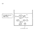
この遊離している膜結合型酵素と膜結合型酵素を固定化されている炭素基材との重水素活性の差が一定の方向性を持って膜結合型酵素が炭素基材に固定化されることによって生じる理論的な考察を行った。結果をまとめて図5に示す。
図5において、Dとは重水素を意味する。
From the above results, the membrane-bound enzyme immobilized on the ketjen black powder showed a deuterium substitution activity of about 2 to 12% of the free enzyme. This is thought to be due to the fact that electrons generated by the deuterium dissociation reaction were transferred to carbon, thereby preventing the deuterium substitution reaction, and it was fixed by the bond between the hydrophobic group of the membrane-bound enzyme and the hydrophobic group of the carbon substrate. It is considered that this indicates that the membrane-bound enzyme is immobilized on the carbon substrate.
The difference in deuterium activity between the free membrane-bound enzyme and the carbon substrate on which the membrane-bound enzyme is immobilized has a certain direction, and the membrane-bound enzyme is immobilized on the carbon substrate. Theoretical considerations arising from The results are summarized in FIG.
In FIG. 5, D means deuterium.
Claims (6)
Priority Applications (1)
| Application Number | Priority Date | Filing Date | Title |
|---|---|---|---|
| JP2008208690A JP5219265B2 (en) | 2008-08-13 | 2008-08-13 | Enzyme electrode and method for producing the same |
Applications Claiming Priority (1)
| Application Number | Priority Date | Filing Date | Title |
|---|---|---|---|
| JP2008208690A JP5219265B2 (en) | 2008-08-13 | 2008-08-13 | Enzyme electrode and method for producing the same |
Publications (2)
| Publication Number | Publication Date |
|---|---|
| JP2010043978A true JP2010043978A (en) | 2010-02-25 |
| JP5219265B2 JP5219265B2 (en) | 2013-06-26 |
Family
ID=42015473
Family Applications (1)
| Application Number | Title | Priority Date | Filing Date |
|---|---|---|---|
| JP2008208690A Expired - Fee Related JP5219265B2 (en) | 2008-08-13 | 2008-08-13 | Enzyme electrode and method for producing the same |
Country Status (1)
| Country | Link |
|---|---|
| JP (1) | JP5219265B2 (en) |
Cited By (2)
| Publication number | Priority date | Publication date | Assignee | Title |
|---|---|---|---|---|
| WO2011162027A1 (en) | 2010-06-25 | 2011-12-29 | ソニー株式会社 | Biofuel cell |
| US9303255B2 (en) | 2010-08-26 | 2016-04-05 | Aisin Seiki Kabushiki Kaisha | Electrode having enzyme crystals immobilized thereon, method for producing electrode having enzyme crystals immobilized thereon, and biological fuel cell and biosensor provided with electrode having enzyme crystals immobilized thereon |
Citations (17)
| Publication number | Priority date | Publication date | Assignee | Title |
|---|---|---|---|---|
| JPS62236483A (en) * | 1986-04-04 | 1987-10-16 | Hitachi Ltd | Immobilized enzyme and production thereof |
| JPH03229144A (en) * | 1989-05-31 | 1991-10-11 | Nakano Vinegar Co Ltd | Oxygen sensor |
| JPH0470558A (en) * | 1990-07-11 | 1992-03-05 | Yamaguchi Pref Gov | Ethanol sensor |
| JP2002214190A (en) * | 2001-01-12 | 2002-07-31 | National Institute Of Advanced Industrial & Technology | Constant-potential electrolytic hydrogen sensor |
| JP2003132930A (en) * | 2001-10-26 | 2003-05-09 | Osaka Gas Co Ltd | Methane fuel cell |
| JP2005501387A (en) * | 2001-08-24 | 2005-01-13 | イシス イノベイション リミテッド | Fuel cell |
| JP2005083873A (en) * | 2003-09-08 | 2005-03-31 | Mitsubishi Pencil Co Ltd | Biosensor |
| JP2006508519A (en) * | 2002-11-27 | 2006-03-09 | セント・ルイス・ユニバーシティ | Immobilization of enzymes used in biofuel cells and sensors |
| JP2006127957A (en) * | 2004-10-29 | 2006-05-18 | Sony Corp | Fuel cell and its manufacturing method |
| JP2007103307A (en) * | 2005-10-07 | 2007-04-19 | Sony Corp | Method of manufacturing fuel cell, fuel cell, method of manufacturing negative electrode for fuel cell, negative electrode for fuel cell, electronic equipment, vehicle, power generating system, co-generation system, method of manufacturing enzyme reaction utilizing device, enzyme reaction utilizing device, method of manufacturing electrode for enzyme reaction utilizing device, electrode for enzyme utilizing device, and immobilization method |
| JP2007121280A (en) * | 2005-09-30 | 2007-05-17 | Canon Inc | Enzyme electrode, sensor using it, and biological fuel cell |
| JP2007225444A (en) * | 2006-02-23 | 2007-09-06 | Denso Corp | Enzyme functional electrode, biosensor and fuel cell |
| JP2007257983A (en) * | 2006-03-23 | 2007-10-04 | Sony Corp | Fuel cell and its manufacturing method, negative electrode for fuel cell and its manufacturing method, electronic equipment, electrode reaction utilization device and its manufacturing method, electrode for electrode reaction utilization device and its manufacturing method, high output agent, and mediator diffusion accelerator |
| JP2008071584A (en) * | 2006-09-13 | 2008-03-27 | Toyota Motor Corp | Electron transfer mediator modification enzyme electrode, and biological fuel cell equipped with this |
| JP2008263803A (en) * | 2007-04-17 | 2008-11-06 | Toyota Motor Corp | Method for isolating and purifying hydrogenase, hydrogenase enzyme solution, and fuel battery using electrode catalyst produced from the hydrogenase enzyme solution |
| JP2008306979A (en) * | 2007-06-14 | 2008-12-25 | Toyota Motor Corp | Modified hydrogenase and enzymatic electrode using the same, and method for modifying hydrogenase |
| JP2009515303A (en) * | 2005-11-02 | 2009-04-09 | セント・ルイス・ユニバーシティ | Direct electron transfer using enzymes in bioanodes, biocathodes, and biofuel cells |
-
2008
- 2008-08-13 JP JP2008208690A patent/JP5219265B2/en not_active Expired - Fee Related
Patent Citations (17)
| Publication number | Priority date | Publication date | Assignee | Title |
|---|---|---|---|---|
| JPS62236483A (en) * | 1986-04-04 | 1987-10-16 | Hitachi Ltd | Immobilized enzyme and production thereof |
| JPH03229144A (en) * | 1989-05-31 | 1991-10-11 | Nakano Vinegar Co Ltd | Oxygen sensor |
| JPH0470558A (en) * | 1990-07-11 | 1992-03-05 | Yamaguchi Pref Gov | Ethanol sensor |
| JP2002214190A (en) * | 2001-01-12 | 2002-07-31 | National Institute Of Advanced Industrial & Technology | Constant-potential electrolytic hydrogen sensor |
| JP2005501387A (en) * | 2001-08-24 | 2005-01-13 | イシス イノベイション リミテッド | Fuel cell |
| JP2003132930A (en) * | 2001-10-26 | 2003-05-09 | Osaka Gas Co Ltd | Methane fuel cell |
| JP2006508519A (en) * | 2002-11-27 | 2006-03-09 | セント・ルイス・ユニバーシティ | Immobilization of enzymes used in biofuel cells and sensors |
| JP2005083873A (en) * | 2003-09-08 | 2005-03-31 | Mitsubishi Pencil Co Ltd | Biosensor |
| JP2006127957A (en) * | 2004-10-29 | 2006-05-18 | Sony Corp | Fuel cell and its manufacturing method |
| JP2007121280A (en) * | 2005-09-30 | 2007-05-17 | Canon Inc | Enzyme electrode, sensor using it, and biological fuel cell |
| JP2007103307A (en) * | 2005-10-07 | 2007-04-19 | Sony Corp | Method of manufacturing fuel cell, fuel cell, method of manufacturing negative electrode for fuel cell, negative electrode for fuel cell, electronic equipment, vehicle, power generating system, co-generation system, method of manufacturing enzyme reaction utilizing device, enzyme reaction utilizing device, method of manufacturing electrode for enzyme reaction utilizing device, electrode for enzyme utilizing device, and immobilization method |
| JP2009515303A (en) * | 2005-11-02 | 2009-04-09 | セント・ルイス・ユニバーシティ | Direct electron transfer using enzymes in bioanodes, biocathodes, and biofuel cells |
| JP2007225444A (en) * | 2006-02-23 | 2007-09-06 | Denso Corp | Enzyme functional electrode, biosensor and fuel cell |
| JP2007257983A (en) * | 2006-03-23 | 2007-10-04 | Sony Corp | Fuel cell and its manufacturing method, negative electrode for fuel cell and its manufacturing method, electronic equipment, electrode reaction utilization device and its manufacturing method, electrode for electrode reaction utilization device and its manufacturing method, high output agent, and mediator diffusion accelerator |
| JP2008071584A (en) * | 2006-09-13 | 2008-03-27 | Toyota Motor Corp | Electron transfer mediator modification enzyme electrode, and biological fuel cell equipped with this |
| JP2008263803A (en) * | 2007-04-17 | 2008-11-06 | Toyota Motor Corp | Method for isolating and purifying hydrogenase, hydrogenase enzyme solution, and fuel battery using electrode catalyst produced from the hydrogenase enzyme solution |
| JP2008306979A (en) * | 2007-06-14 | 2008-12-25 | Toyota Motor Corp | Modified hydrogenase and enzymatic electrode using the same, and method for modifying hydrogenase |
Cited By (2)
| Publication number | Priority date | Publication date | Assignee | Title |
|---|---|---|---|---|
| WO2011162027A1 (en) | 2010-06-25 | 2011-12-29 | ソニー株式会社 | Biofuel cell |
| US9303255B2 (en) | 2010-08-26 | 2016-04-05 | Aisin Seiki Kabushiki Kaisha | Electrode having enzyme crystals immobilized thereon, method for producing electrode having enzyme crystals immobilized thereon, and biological fuel cell and biosensor provided with electrode having enzyme crystals immobilized thereon |
Also Published As
| Publication number | Publication date |
|---|---|
| JP5219265B2 (en) | 2013-06-26 |
Similar Documents
| Publication | Publication Date | Title |
|---|---|---|
| Liu et al. | Production of electricity during wastewater treatment using a single chamber microbial fuel cell | |
| US7238440B2 (en) | Membrane free fuel cell | |
| Kim et al. | Single-enzyme nanoparticles armored by a nanometer-scale organic/inorganic network | |
| Prasad et al. | Direct electron transfer with yeast cells and construction of a mediatorless microbial fuel cell | |
| Arechederra et al. | Development of glycerol/O2 biofuel cell | |
| Muguruma et al. | Mediatorless direct electron transfer between flavin adenine dinucleotide-dependent glucose dehydrogenase and single-walled carbon nanotubes | |
| Ryu et al. | Direct extraction of photosynthetic electrons from single algal cells by nanoprobing system | |
| Yuan et al. | Strategies for bioelectrochemical CO2 reduction | |
| Sakai et al. | High-power formate/dioxygen biofuel cell based on mediated electron transfer type bioelectrocatalysis | |
| JP4588649B2 (en) | Enzyme functional electrode and biosensor and fuel cell | |
| JP2006093090A (en) | Fuel cell, its using method and its cathode electrode, electronic equipment, electrode reaction utilizing device and its electrode | |
| Moon et al. | Recent progress in formate dehydrogenase (FDH) as a non-photosynthetic CO2 utilizing enzyme: A short review | |
| NL1031147C2 (en) | Device comprising a new cathode system and method for generating electrical energy with the aid of this. | |
| Xiu et al. | Hydrogen‐mediated electron transfer in hybrid microbial–inorganic systems and application in energy and the environment | |
| Alvarez-Malmagro et al. | Bioelectrocatalytic activity of W-formate dehydrogenase covalently immobilized on functionalized gold and graphite electrodes | |
| Karyakin et al. | The limiting performance characteristics in bioelectrocatalysis of hydrogenase enzymes | |
| CN107429264A (en) | Method and apparatus for chemical recycling of carbon dioxide | |
| Tsujimura et al. | CueO-immobilized porous carbon electrode exhibiting improved performance of electrochemical reduction of dioxygen to water | |
| Yan et al. | Photofuel cell coupling with redox cycling as a highly sensitive and selective self-powered sensing platform for the detection of tyrosinase activity | |
| Ratautas et al. | Mediatorless electron transfer in glucose dehydrogenase/laccase system adsorbed on carbon nanotubes | |
| Baca et al. | Microbial electrochemical systems with future perspectives using advanced nanomaterials and microfluidics | |
| JP2005501387A (en) | Fuel cell | |
| Herkendell | Status update on bioelectrochemical systems: prospects for carbon electrode design and scale-up | |
| CN101151764A (en) | Immobilized enzymes in biocathodes | |
| Lojou et al. | Kinetic studies on the electron transfer between various c-type cytochromes and iron (III) using a voltammetric approach |
Legal Events
| Date | Code | Title | Description |
|---|---|---|---|
| A621 | Written request for application examination |
Free format text: JAPANESE INTERMEDIATE CODE: A621 Effective date: 20110413 |
|
| A521 | Written amendment |
Free format text: JAPANESE INTERMEDIATE CODE: A821 Effective date: 20110413 |
|
| A977 | Report on retrieval |
Free format text: JAPANESE INTERMEDIATE CODE: A971007 Effective date: 20120614 |
|
| A131 | Notification of reasons for refusal |
Free format text: JAPANESE INTERMEDIATE CODE: A131 Effective date: 20120717 |
|
| A521 | Written amendment |
Free format text: JAPANESE INTERMEDIATE CODE: A523 Effective date: 20120907 |
|
| TRDD | Decision of grant or rejection written | ||
| A01 | Written decision to grant a patent or to grant a registration (utility model) |
Free format text: JAPANESE INTERMEDIATE CODE: A01 Effective date: 20130205 |
|
| A61 | First payment of annual fees (during grant procedure) |
Free format text: JAPANESE INTERMEDIATE CODE: A61 Effective date: 20130304 |
|
| FPAY | Renewal fee payment (event date is renewal date of database) |
Free format text: PAYMENT UNTIL: 20160315 Year of fee payment: 3 |
|
| R151 | Written notification of patent or utility model registration |
Ref document number: 5219265 Country of ref document: JP Free format text: JAPANESE INTERMEDIATE CODE: R151 |
|
| FPAY | Renewal fee payment (event date is renewal date of database) |
Free format text: PAYMENT UNTIL: 20160315 Year of fee payment: 3 |
|
| R250 | Receipt of annual fees |
Free format text: JAPANESE INTERMEDIATE CODE: R250 |
|
| R250 | Receipt of annual fees |
Free format text: JAPANESE INTERMEDIATE CODE: R250 |
|
| R250 | Receipt of annual fees |
Free format text: JAPANESE INTERMEDIATE CODE: R250 |
|
| LAPS | Cancellation because of no payment of annual fees |