JP2010043837A - Ultra low injection angle fuel hole in combustor fuel nozzle - Google Patents
Ultra low injection angle fuel hole in combustor fuel nozzle Download PDFInfo
- Publication number
- JP2010043837A JP2010043837A JP2009140642A JP2009140642A JP2010043837A JP 2010043837 A JP2010043837 A JP 2010043837A JP 2009140642 A JP2009140642 A JP 2009140642A JP 2009140642 A JP2009140642 A JP 2009140642A JP 2010043837 A JP2010043837 A JP 2010043837A
- Authority
- JP
- Japan
- Prior art keywords
- fuel
- fuel nozzle
- swirler
- mixing passage
- swirler vanes
- Prior art date
- Legal status (The legal status is an assumption and is not a legal conclusion. Google has not performed a legal analysis and makes no representation as to the accuracy of the status listed.)
- Pending
Links
Images


Classifications
-
- F—MECHANICAL ENGINEERING; LIGHTING; HEATING; WEAPONS; BLASTING
- F23—COMBUSTION APPARATUS; COMBUSTION PROCESSES
- F23R—GENERATING COMBUSTION PRODUCTS OF HIGH PRESSURE OR HIGH VELOCITY, e.g. GAS-TURBINE COMBUSTION CHAMBERS
- F23R3/00—Continuous combustion chambers using liquid or gaseous fuel
- F23R3/28—Continuous combustion chambers using liquid or gaseous fuel characterised by the fuel supply
- F23R3/286—Continuous combustion chambers using liquid or gaseous fuel characterised by the fuel supply having fuel-air premixing devices
-
- F—MECHANICAL ENGINEERING; LIGHTING; HEATING; WEAPONS; BLASTING
- F23—COMBUSTION APPARATUS; COMBUSTION PROCESSES
- F23R—GENERATING COMBUSTION PRODUCTS OF HIGH PRESSURE OR HIGH VELOCITY, e.g. GAS-TURBINE COMBUSTION CHAMBERS
- F23R3/00—Continuous combustion chambers using liquid or gaseous fuel
- F23R3/02—Continuous combustion chambers using liquid or gaseous fuel characterised by the air-flow or gas-flow configuration
- F23R3/04—Air inlet arrangements
- F23R3/10—Air inlet arrangements for primary air
- F23R3/12—Air inlet arrangements for primary air inducing a vortex
- F23R3/14—Air inlet arrangements for primary air inducing a vortex by using swirl vanes
-
- B—PERFORMING OPERATIONS; TRANSPORTING
- B33—ADDITIVE MANUFACTURING TECHNOLOGY
- B33Y—ADDITIVE MANUFACTURING, i.e. MANUFACTURING OF THREE-DIMENSIONAL [3-D] OBJECTS BY ADDITIVE DEPOSITION, ADDITIVE AGGLOMERATION OR ADDITIVE LAYERING, e.g. BY 3-D PRINTING, STEREOLITHOGRAPHY OR SELECTIVE LASER SINTERING
- B33Y80/00—Products made by additive manufacturing
-
- F—MECHANICAL ENGINEERING; LIGHTING; HEATING; WEAPONS; BLASTING
- F23—COMBUSTION APPARATUS; COMBUSTION PROCESSES
- F23C—METHODS OR APPARATUS FOR COMBUSTION USING FLUID FUEL OR SOLID FUEL SUSPENDED IN A CARRIER GAS OR AIR
- F23C2900/00—Special features of, or arrangements for combustion apparatus using fluid fuels or solid fuels suspended in air; Combustion processes therefor
- F23C2900/07001—Air swirling vanes incorporating fuel injectors
Abstract
Description
本発明は、総括的にはガスタービンに関する。より具体的には、本発明は、ガスタービンエンジン用の燃料ノズルに関する。 The present invention relates generally to gas turbines. More specifically, the present invention relates to a fuel nozzle for a gas turbine engine.
ガスタービンは一般的に、該ガスタービンの燃焼器セクション内に多数の燃料ノズル(又はスウォズル)を含む。各ノズルは、燃焼のために燃料及び空気の混合気を燃焼室に送給するための1以上の通路を有する部品である。多くの場合、燃料ノズルは、燃焼に先立って燃料及び空気の混合を改善して全体的に均質な混合気にするためのスワーラを含む。スワーラは、ノズルから延びかつ空気力学的輪郭を有する複数のベーンを含む。多くの場合、スワーラベーンは、該スワーラベーンの表面上の燃料孔に燃料を供給する通路を含む。燃料が燃料孔から流出すると、燃料は、スワーラベーンを通過して流れる流体、一般的には空気と混合する。燃料孔は一般的に、スワーラベーン内の燃料プレナムをそこで燃料が空気と混合する通路に連結する直線孔として構成される。従って、燃料孔は一般的に、通過空気に対してほぼ垂直に燃料を噴射する。通過空気流内に燃料が噴射されると、ジェット・イン・クロスフロー現象が生じ、それにより、噴射孔の下流であるが燃焼ゾーンのほぼ上流に低速度流の再循環ゾーンが形成される。 A gas turbine typically includes a number of fuel nozzles (or swozzles) within the combustor section of the gas turbine. Each nozzle is a component having one or more passages for delivering a fuel and air mixture to the combustion chamber for combustion. In many cases, the fuel nozzle includes a swirler to improve the fuel and air mixing prior to combustion to a generally homogeneous mixture. The swirler includes a plurality of vanes extending from the nozzle and having an aerodynamic profile. Often, swirler vanes include passages that supply fuel to fuel holes on the surface of the swirler vanes. As fuel flows out of the fuel holes, the fuel mixes with the fluid flowing through the swirler vanes, typically air. The fuel holes are typically configured as straight holes that connect the fuel plenum in the swirler vane to a passage where the fuel mixes with air. Thus, the fuel holes typically inject fuel substantially perpendicular to the passing air. When fuel is injected into the passing air stream, a jet-in-cross flow phenomenon occurs, thereby creating a low velocity flow recirculation zone downstream of the injection holes but substantially upstream of the combustion zone.
再循環ゾーンは、特に合成ガス、カーボン無含有合成ガス、及び水素−天然ガスブレンドのような高反応性高水素燃料の場合に問題である。これらの燃料は、低速度再循環ゾーン内での燃料の滞留時間よりも極めて短いブローオフ又はブローアウト時間を有し、従って点火源を設けた場合には、再循環ゾーン内におけるあらゆる燃料が着火しかつスワーラベーン近くで燃焼し続けて、燃料ノズル及び場合によってはガスタービンのその他の部品を損傷させるおそれがある。 The recirculation zone is particularly problematic for highly reactive high hydrogen fuels such as synthesis gas, carbon-free synthesis gas, and hydrogen-natural gas blends. These fuels have a blow-off or blow-out time that is much shorter than the residence time of the fuel in the low-speed recirculation zone, so if an ignition source is provided, any fuel in the recirculation zone will ignite. And it can continue to burn near the swirler vanes and damage the fuel nozzles and possibly other parts of the gas turbine.
本発明の1つの態様によると、燃焼器用の燃料ノズルは、それを通して流体が燃焼区域に向かって導かれる混合通路と、該混合通路内に配置された複数のスワーラベーンとを含む。複数のスワーラベーンの各スワーラベーンは、それを通して燃料が該複数のスワーラベーンの外表面にほぼ平行な噴射方向において混合通路に流入し、それによって燃料ノズルの保炎傾向を減少させる1以上の燃料孔を含む。 According to one aspect of the invention, a fuel nozzle for a combustor includes a mixing passage through which fluid is directed toward a combustion zone and a plurality of swirler vanes disposed within the mixing passage. Each swirler vane of the plurality of swirler vanes includes one or more fuel holes through which fuel flows into the mixing passage in an injection direction substantially parallel to the outer surface of the plurality of swirler vanes, thereby reducing the flame holding tendency of the fuel nozzle. .
本発明の別の態様によると、燃焼器用の燃料ノズルを作動させる方法は、複数のスワーラベーンを通過する混合通路内に流体を流すステップと、複数のスワーラベーンの外表面にほぼ平行な噴射方向において混合通路内に燃料を噴射し、それによって燃料ノズルの保炎傾向を減少させるステップとを含む。 In accordance with another aspect of the invention, a method of operating a fuel nozzle for a combustor includes flowing a fluid in a mixing passage through a plurality of swirler vanes and mixing in an injection direction substantially parallel to an outer surface of the plurality of swirler vanes. Injecting fuel into the passageway, thereby reducing the flame holding tendency of the fuel nozzle.
これらの及びその他の利点並びに特徴は、図面と関連させてなした以下の詳細な説明から明らかになるであろう。 These and other advantages and features will become apparent from the following detailed description taken in conjunction with the drawings.
本発明は、本明細書と共に提出した特許請求の範囲において具体的に指摘しかつ明確に特許請求している。本発明の上記の及びその他の目的、特徴並びに利点は、添付図面と関連させてなした以下の詳細な説明から明らかである。 The invention is specifically pointed out and distinctly claimed in the claims appended hereto. The above and other objects, features and advantages of the present invention will be apparent from the following detailed description taken in conjunction with the accompanying drawings.
この詳細な説明は、図面を参照しながら実施例によって、その利点及び特徴と共に本発明の実施形態を説明する。 The detailed description explains embodiments of the invention, together with advantages and features, by way of example with reference to the drawings.
図1に示すのは、スワーラ12を含む燃料ノズル10の一部分である。スワーラは、ノズル入口14から流体流、通常は空気を受けまたその空気を燃料と混合して空気/燃料混合気にするように構成されかつ配置される。空気/燃料混合気は次に、下流に進み、下流において該混合気は、燃焼区域16内で点火される。図2に最も良く示しているように、スワーラ12は、中心本体20の円周方向周りに配置されかつシュラウド22まで延びる複数のスワーラベーン18を含む。図1の実施形態のスワーラ12は、1つの実施形態では、直接金属レーザ焼結(DMLS)法によって製作されるが、例えば鋳造法、溶接法又は機械加工法を含むその他の製作方法も、本開示の技術的範囲内で意図している。
Shown in FIG. 1 is a portion of a
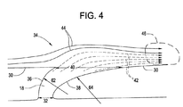
図3に最も良く示しているように、複数のスワーラベーン18は、1以上の内部プレナム24を有することができる。プレナム24は、1以上の中心本体孔26において中心本体20に連結され、また該中心本体20から1以上のプレナム24を通して燃料を流しかつスワーラベーン外表面30に配置された1以上の孔28を通して該プレナム24から流出させることができるように構成される。図4に示すように、各燃料孔28は、幾つかの実施形態では円形又はレーストラック形断面を有する調量セクションを含み、この調量セクションは、燃料孔28の最小断面積であって該燃料孔28を通って混合通路34内に流れる燃料流量を調整する。燃料孔28のリーディング壁36は、緩やかに湾曲しており、リーディング曲率半径62を有することができかつ約33°の角度で外表面30と交わる。この図示した実施形態では、角度は約33°であるが、例えば約15〜55°の範囲内の角度のようなその他の好適な角度を使用することができることを理解されたい。燃料孔28のトレーリング壁38は、リーディング曲率半径62よりも大きいトレーリング曲率半径64を有し、かつ該トレーリング壁38が外表面30と交わる時に該トレーリング壁38が該外表面30に対してほぼ接線方向となるように配置される。さらに、トレーリング曲率半径64は、例えば調量セクション32から混合通路34まで増大するように変化させることができる。得られた燃料孔28は、調量セクション32の断面積よりも大きい出口断面積40を有し、それにより流れの拡散を可能にする。さらに、トレーリング壁38が外表面30と接線方向に交わるので、燃料は、矢印42で示すように、トレーリング壁38の近くで、混合通路34を通る空気流44にほぼ平行に該混合通路34内に噴射される。空気流44内に燃料42を噴射することにより、該空気流44との燃料42のほぼ並流が形成されて、典型的な燃料孔構成での燃料の再循環ゾーンとは対照的に高下流方向速度を有する燃料42で下流区域46を満たす。
As best shown in FIG. 3, the plurality of
図5及び図6に示すのは、燃料孔28の出口48の2つの構成の図である。幾つかの実施形態では、図5に示すように、出口48は、下流端縁部50、上流端縁部52及び2つの側方端縁部54を含む。図5の実施形態では、側方端縁部54は、互いにほぼ平行かつ流れ方向56にほぼ平行であるか、また/又は流れ方向56にほぼ平行である。他の実施形態では、図6に示すように、出口48の側方端縁部54は、出口48の幅60が上流端縁部52においてよりも下流端縁部50において大きくなるように、流れ方向56からフレア角度58で広がって(フレアして)いる。逆に、幾つかの実施形態では、下流端縁部50における幅60が上流端縁部52における幅60よりも小さくなるように側方端縁部54をフレアさせるのが有利である場合もある。図5及び図6に示す出口48の構成は、同一のベーン18内で又は同一の燃料ノズル10内で共に利用することができることを理解されたい。さらに、本明細書に記載した出口48構成は、単なる例示に過ぎず、本発明の技術的範囲内でその他の出口48構成も考えられる。
FIGS. 5 and 6 show two configurations of the
本発明の実施形態による燃料孔28は、種々の製作方法により形成することができる。幾つかの実施形態では、燃料孔28は、複数のスワーラベーン18の直接金属レーザ焼結(DMLS)時に形成される。
The
本明細書に記載した燃料孔28により、空気流44にほぼ平行な混合通路34内への燃料42の噴射が得られ、それにより、燃焼ゾーン(図示せず)に向かう高速度の燃料42の流れが生じる。高速度の流れは、再循環ゾーンの形成を縮小し、それによって燃料ノズル10の保炎傾向を減少させる。
The
限られた数の実施形態のみに関して本発明を詳細に説明してきたが、本発明がそのような開示した実施形態に限定されるものではないことは、容易に理解される筈である。むしろ、本発明は、これまで説明していないが本発明の技術思想及び技術的範囲に相応するあらゆる数の変形、変更、置換え又は均等な構成を組込むように改良することができる。さらに、本発明の様々な実施形態について説明してきたが、本発明の態様は説明した実施形態の一部のみを含むことができることを理解されたい。従って、本発明は、上記の説明によって限定されるものと見なすべきでなく、本発明は、特許請求の範囲の技術的範囲によってのみ限定される。 Although the invention has been described in detail with respect to only a limited number of embodiments, it should be readily understood that the invention is not limited to such disclosed embodiments. Rather, the invention can be modified to incorporate any number of variations, alterations, substitutions or equivalent arrangements not heretofore described, but which are commensurate with the spirit and scope of the invention. Moreover, while various embodiments of the invention have been described, it is to be understood that aspects of the invention can include only some of the described embodiments. Accordingly, the invention is not to be seen as limited by the foregoing description, but is limited only by the scope of the claims.
10 燃料ノズル
12 スワーラ
14 ノズル入口
16 燃焼区域
18 スワーラベーン
20 中心本体
22 シュラウド
24 プレナム
26 中心本体孔
28 燃料孔
30 外表面
32 調量セクション
34 混合通路
36 リーディング壁
38 トレーリング壁
40 断面積
42 矢印
44 空気流
46 下流区域
48 出口
50 下流端縁部
52 上流端縁部
54 側方端縁部
56 流れ方向
58 フレア角度
60 幅
62 曲率
64 曲率
10
Claims (10)
それを通して流体が燃焼区域(16)に向かって導かれる混合通路(34)と、
前記混合通路(34)内に配置された複数のスワーラベーン(18)と、を含み、
前記複数のスワーラベーン(18)の各スワーラベーン(18)が、それを通して燃料が該複数のスワーラベーン(18)の外表面(30)にほぼ平行な噴射方向において前記混合通路(34)に流入し、それによって該燃料ノズル(10)の保炎傾向を減少させる1以上の燃料孔(28)を
含む燃料ノズル(10)。 A fuel nozzle (10) for a combustor,
A mixing passageway (34) through which fluid is directed towards the combustion zone (16);
A plurality of swirler vanes (18) disposed in the mixing passage (34);
Each swirler vane (18) of the plurality of swirler vanes (18) passes through the mixing passage (34) through which fuel flows in an injection direction generally parallel to the outer surface (30) of the plurality of swirler vanes (18), A fuel nozzle (10) comprising one or more fuel holes (28) that reduces the flame holding tendency of the fuel nozzle (10).
複数のスワーラベーン(18)を通過する混合通路(34)内に流体を流すステップと、
前記複数のスワーラベーン(18)の外表面(30)にほぼ平行な噴射方向において前記混合通路(34)内に燃料を噴射し、それによって前記燃料ノズル(10)の保炎傾向を減少させるステップと
を含む方法。 A method of operating a fuel nozzle (10) for a combustor, comprising:
Flowing a fluid in a mixing passage (34) through a plurality of swirler vanes (18);
Injecting fuel into the mixing passage (34) in an injection direction substantially parallel to the outer surface (30) of the plurality of swirler vanes (18), thereby reducing the flame holding tendency of the fuel nozzle (10); Including methods.
Applications Claiming Priority (1)
| Application Number | Priority Date | Filing Date | Title |
|---|---|---|---|
| US12/190,918 US8291705B2 (en) | 2008-08-13 | 2008-08-13 | Ultra low injection angle fuel holes in a combustor fuel nozzle |
Publications (2)
| Publication Number | Publication Date |
|---|---|
| JP2010043837A true JP2010043837A (en) | 2010-02-25 |
| JP2010043837A5 JP2010043837A5 (en) | 2013-03-07 |
Family
ID=41528288
Family Applications (1)
| Application Number | Title | Priority Date | Filing Date |
|---|---|---|---|
| JP2009140642A Pending JP2010043837A (en) | 2008-08-13 | 2009-06-12 | Ultra low injection angle fuel hole in combustor fuel nozzle |
Country Status (5)
| Country | Link |
|---|---|
| US (1) | US8291705B2 (en) |
| JP (1) | JP2010043837A (en) |
| CN (1) | CN101650032A (en) |
| DE (1) | DE102009025961A1 (en) |
| FR (1) | FR2935042A1 (en) |
Families Citing this family (6)
| Publication number | Priority date | Publication date | Assignee | Title |
|---|---|---|---|---|
| US9121609B2 (en) * | 2008-10-14 | 2015-09-01 | General Electric Company | Method and apparatus for introducing diluent flow into a combustor |
| US20130040254A1 (en) * | 2011-08-08 | 2013-02-14 | General Electric Company | System and method for monitoring a combustor |
| US20130192243A1 (en) * | 2012-01-31 | 2013-08-01 | Matthew Patrick Boespflug | Fuel nozzle for a gas turbine engine and method of operating the same |
| US9289826B2 (en) | 2012-09-17 | 2016-03-22 | Honeywell International Inc. | Turbine stator airfoil assemblies and methods for their manufacture |
| US9400104B2 (en) | 2012-09-28 | 2016-07-26 | United Technologies Corporation | Flow modifier for combustor fuel nozzle tip |
| KR102363091B1 (en) | 2020-07-06 | 2022-02-14 | 두산중공업 주식회사 | Nozzle for combustor, combustor, and gas turbine including the same |
Citations (1)
| Publication number | Priority date | Publication date | Assignee | Title |
|---|---|---|---|---|
| JP2008089298A (en) * | 2006-10-03 | 2008-04-17 | General Electric Co <Ge> | Function enhancement with liquid fuel for natural gas swirl stabilized nozzle and method |
Family Cites Families (15)
| Publication number | Priority date | Publication date | Assignee | Title |
|---|---|---|---|---|
| GB1139004A (en) * | 1966-02-28 | 1969-01-08 | Mini Of Technology | Improvements in or relating to combustion devices |
| US4887425A (en) * | 1988-03-18 | 1989-12-19 | General Electric Company | Fuel spraybar |
| US5351477A (en) * | 1993-12-21 | 1994-10-04 | General Electric Company | Dual fuel mixer for gas turbine combustor |
| EP1096201A1 (en) * | 1999-10-29 | 2001-05-02 | Siemens Aktiengesellschaft | Burner |
| US6619026B2 (en) * | 2001-08-27 | 2003-09-16 | Siemens Westinghouse Power Corporation | Reheat combustor for gas combustion turbine |
| US6655145B2 (en) * | 2001-12-20 | 2003-12-02 | Solar Turbings Inc | Fuel nozzle for a gas turbine engine |
| US6832481B2 (en) * | 2002-09-26 | 2004-12-21 | Siemens Westinghouse Power Corporation | Turbine engine fuel nozzle |
| ES2288687T3 (en) * | 2003-07-04 | 2008-01-16 | Siemens Aktiengesellschaft | OPEN REFRIGERATION COMPONENT FOR A GAS TURBINE, COMBUSTION CHAMBER AND GAS TURBINE. |
| US7596950B2 (en) * | 2005-09-16 | 2009-10-06 | General Electric Company | Augmentor radial fuel spray bar with counterswirling heat shield |
| US7703288B2 (en) * | 2005-09-30 | 2010-04-27 | Solar Turbines Inc. | Fuel nozzle having swirler-integrated radial fuel jet |
| US20070163114A1 (en) * | 2006-01-13 | 2007-07-19 | General Electric Company | Methods for fabricating components |
| EP1847696A1 (en) * | 2006-04-21 | 2007-10-24 | Siemens Aktiengesellschaft | Component for a secondary combustion system in a gas turbine and corresponding gas turbine. |
| EP1847684A1 (en) * | 2006-04-21 | 2007-10-24 | Siemens Aktiengesellschaft | Turbine blade |
| US20080078182A1 (en) * | 2006-09-29 | 2008-04-03 | Andrei Tristan Evulet | Premixing device, gas turbines comprising the premixing device, and methods of use |
| US20080134685A1 (en) * | 2006-12-07 | 2008-06-12 | Ronald Scott Bunker | Gas turbine guide vanes with tandem airfoils and fuel injection and method of use |
-
2008
- 2008-08-13 US US12/190,918 patent/US8291705B2/en not_active Expired - Fee Related
-
2009
- 2009-06-10 DE DE102009025961A patent/DE102009025961A1/en not_active Withdrawn
- 2009-06-11 FR FR0953896A patent/FR2935042A1/en not_active Withdrawn
- 2009-06-12 JP JP2009140642A patent/JP2010043837A/en active Pending
- 2009-06-15 CN CN200910149455A patent/CN101650032A/en active Pending
Patent Citations (1)
| Publication number | Priority date | Publication date | Assignee | Title |
|---|---|---|---|---|
| JP2008089298A (en) * | 2006-10-03 | 2008-04-17 | General Electric Co <Ge> | Function enhancement with liquid fuel for natural gas swirl stabilized nozzle and method |
Also Published As
| Publication number | Publication date |
|---|---|
| US8291705B2 (en) | 2012-10-23 |
| DE102009025961A1 (en) | 2010-02-18 |
| US20100037614A1 (en) | 2010-02-18 |
| FR2935042A1 (en) | 2010-02-19 |
| CN101650032A (en) | 2010-02-17 |
Similar Documents
| Publication | Publication Date | Title |
|---|---|---|
| JP5773342B2 (en) | Fuel injection device | |
| US8393157B2 (en) | Swozzle design for gas turbine combustor | |
| JP6335903B2 (en) | Flame sheet combustor dome | |
| JP5772245B2 (en) | Fuel injection device | |
| US8925323B2 (en) | Fuel/air premixing system for turbine engine | |
| RU2430307C2 (en) | Air-fuel mix injector, combustion chamber and gas turbine engine with said injector | |
| EP2218966B1 (en) | Fuel injection for gas turbine combustors | |
| CA2820071C (en) | Axial swirler for a gas turbine burner | |
| JP5850900B2 (en) | Reheat burner arrangement | |
| CN102798147B (en) | For the system and method for the current control in gas-turbine unit | |
| KR102543858B1 (en) | System and method having annular flow path architecture | |
| JP5798301B2 (en) | Gas turbine burner | |
| US20120297784A1 (en) | System and method for flow control in gas turbine engine | |
| JP2010159951A (en) | Method and system to enhance flame holding in gas turbine engine | |
| JP2011075271A (en) | Apparatus and method for gas turbine nozzle | |
| JP2010060275A (en) | Turning angle of secondary fuel nozzle for turbomachinery combustor | |
| JP2010043837A (en) | Ultra low injection angle fuel hole in combustor fuel nozzle | |
| US20180045414A1 (en) | Swirler, burner and combustor for a gas turbine engine | |
| JP2004526933A (en) | Burner device that mixes fuel and air to burn | |
| JP2013238386A (en) | Fuel injector with mixing circuit | |
| WO2011092779A1 (en) | Gas turbine combustor | |
| KR102405991B1 (en) | Flamesheet combustor contoured liner | |
| JP6092007B2 (en) | Gas turbine combustor | |
| US20150033752A1 (en) | Gas turbine combustion system and method of flame stabilization in such a system | |
| JP6417620B2 (en) | Combustor, gas turbine |
Legal Events
| Date | Code | Title | Description |
|---|---|---|---|
| A621 | Written request for application examination |
Free format text: JAPANESE INTERMEDIATE CODE: A621 Effective date: 20120607 |
|
| A521 | Request for written amendment filed |
Free format text: JAPANESE INTERMEDIATE CODE: A523 Effective date: 20130111 |
|
| A621 | Written request for application examination |
Free format text: JAPANESE INTERMEDIATE CODE: A621 Effective date: 20130111 |
|
| A871 | Explanation of circumstances concerning accelerated examination |
Free format text: JAPANESE INTERMEDIATE CODE: A871 Effective date: 20130111 |
|
| A975 | Report on accelerated examination |
Free format text: JAPANESE INTERMEDIATE CODE: A971005 Effective date: 20130131 |
|
| A131 | Notification of reasons for refusal |
Free format text: JAPANESE INTERMEDIATE CODE: A131 Effective date: 20130409 |
|
| A977 | Report on retrieval |
Free format text: JAPANESE INTERMEDIATE CODE: A971007 Effective date: 20130411 |
|
| A601 | Written request for extension of time |
Free format text: JAPANESE INTERMEDIATE CODE: A601 Effective date: 20130709 |
|
| A602 | Written permission of extension of time |
Free format text: JAPANESE INTERMEDIATE CODE: A602 Effective date: 20130712 |
|
| A601 | Written request for extension of time |
Free format text: JAPANESE INTERMEDIATE CODE: A601 Effective date: 20130809 |
|
| A602 | Written permission of extension of time |
Free format text: JAPANESE INTERMEDIATE CODE: A602 Effective date: 20130814 |
|
| A601 | Written request for extension of time |
Free format text: JAPANESE INTERMEDIATE CODE: A601 Effective date: 20130909 |
|
| A602 | Written permission of extension of time |
Free format text: JAPANESE INTERMEDIATE CODE: A602 Effective date: 20130912 |
|
| A521 | Request for written amendment filed |
Free format text: JAPANESE INTERMEDIATE CODE: A523 Effective date: 20131008 |
|
| A02 | Decision of refusal |
Free format text: JAPANESE INTERMEDIATE CODE: A02 Effective date: 20131203 |