JP2010043786A - Air conditioner - Google Patents
Air conditioner Download PDFInfo
- Publication number
- JP2010043786A JP2010043786A JP2008207828A JP2008207828A JP2010043786A JP 2010043786 A JP2010043786 A JP 2010043786A JP 2008207828 A JP2008207828 A JP 2008207828A JP 2008207828 A JP2008207828 A JP 2008207828A JP 2010043786 A JP2010043786 A JP 2010043786A
- Authority
- JP
- Japan
- Prior art keywords
- dust
- roll filter
- roll
- filter
- brush
- Prior art date
- Legal status (The legal status is an assumption and is not a legal conclusion. Google has not performed a legal analysis and makes no representation as to the accuracy of the status listed.)
- Granted
Links
Images


Abstract
Description
本発明は、吸込空気の塵埃を捕集するフィルタを備えた空気調和機に関する。 The present invention relates to an air conditioner provided with a filter that collects dust of suction air.
従来、空気調和機において吸込空気中の塵埃を除去するフィルタのメンテナンスを容易にすべく、フィルタから塵埃を取り除く塵埃除去部を設けたものが提案されている(例えば、特許文献1参照。)。この塵埃除去部は、フィルタに付着した塵埃を除去する回転ブラシと、この回転ブラシで除去した塵埃を捕集するダストボックスと、このダストボックス及び回転ブラシをエアフィルタに沿って移動させるガイドレール及び駆動モータと、を吸込グリル上に設けた構成となっている。
しかし、従来の構成では、吸込グリル上にエアフィルタ、回転ブラシ、ダストボックス、ガイドレール及び駆動モータ等が配置されているため、この吸込グリルを昇降させる昇降モータを含む機構の負荷が大きく、大きな重量を安定して昇降させる能力が要求されるという問題があった。
そこで、本発明は、上述した従来の技術が有する課題を解消し、ダストボックスを昇降する際の負荷を軽減するともに、このダストボックス内の塵埃を容易に廃棄することができる空気調和機を提供することを目的とする。
However, in the conventional configuration, since an air filter, a rotating brush, a dust box, a guide rail, a drive motor, and the like are arranged on the suction grill, the load on the mechanism including the lifting motor that lifts and lowers the suction grill is large and heavy. There was a problem that the ability to move up and down stably was required.
Therefore, the present invention provides an air conditioner that solves the problems of the conventional technology described above, reduces the load when the dust box is raised and lowered, and can easily dispose of dust in the dust box. With the goal.
上述課題を解決するため、本発明は、熱交換器及び送風機を有する本体ユニットと、この本体ユニットの下方に配置され、被調和室の空気を吸い込む吸込口を有する化粧パネルとを備えた空気調和機において、前記吸込口内の一方側においてロール状に巻き回され、前記吸込口と前記送風機との間に繰り出されて前記吸込口からの吸込空気の塵埃を捕集するロールフィルタと、前記ロールフィルタを繰り出し或いは巻き取る巻取手段とを設け、前記ロールフィルタの表面に当接して前記ロールフィルタの塵埃を除去する除去手段と、前記除去手段により前記ロールフィルタから除去された塵埃が当該除去手段から移されて集積されるダストボックスとを備え、さらに、前記ダストボックスを、前記ロールフィルタ及び前記除去手段に対して昇降可能に支持する昇降手段を備えたことを特徴とする。 In order to solve the above-described problems, the present invention provides an air conditioner including a main body unit having a heat exchanger and a blower, and a decorative panel that is disposed below the main body unit and has a suction port for sucking air in a conditioned room. A roll filter that is wound in a roll shape on one side of the suction port and that is drawn out between the suction port and the blower to collect dust from the suction air from the suction port, and the roll filter Removing means for removing the dust from the roll filter in contact with the surface of the roll filter, and dust removed from the roll filter by the removing means from the removing means. A dust box that is transferred and integrated, and further, the dust box is raised with respect to the roll filter and the removing means. Characterized by comprising a lifting means for movably supported.
この構成によれば、ロールフィルタを巻取手段によって繰り出し或いは巻き取ることにより、ロールフィルタの表面に当接する除去手段によって、ロールフィルタの表面に付着した塵埃を容易に除去することができ、除去された塵埃が集積されるダストボックスを昇降させることでダストボックス内の塵埃を簡単に取り除くことができる。これにより、フィルタのメンテナンスが容易で、ダストボックスを昇降する際の負荷が非常に軽くて済む空気調和機を提供できる。また、長期間にわたって交換せず使用可能なロールフィルタから塵埃を除去することで、ロールフィルタの交換周期をさらに長くすることができ、メンテナンスに係る労力を大幅に軽減できる。 According to this configuration, the dust attached to the surface of the roll filter can be easily removed and removed by the removing means that comes into contact with the surface of the roll filter by feeding or winding the roll filter by the winding means. The dust in the dust box can be easily removed by raising and lowering the dust box in which the accumulated dust is accumulated. Accordingly, it is possible to provide an air conditioner in which the maintenance of the filter is easy and the load when raising and lowering the dust box is very light. Moreover, by removing dust from the roll filter that can be used without replacement over a long period of time, the replacement period of the roll filter can be further extended, and the labor involved in maintenance can be greatly reduced.
この構成において、前記吸込口からの吸込空気の塵埃を捕集した前記ロールフィルタを、前記巻取手段によって前記吸込口と前記送風機との間から前記吸込口内の一方側或いは他方側に巻き取りつつ前記除去手段によって塵埃を除去し、その後に、塵埃を除去した部分の前記ロールフィルタを再び前記吸込口と前記送風機との間に繰り出す構成としてもよい。 In this configuration, the roll filter that collects dust from the suction air from the suction port is wound around one side or the other side in the suction port from between the suction port and the blower by the winding means. It is good also as a structure which removes dust with the said removal means, and after that, the said roll filter of the part from which dust was removed is let out between the said suction inlet and the said air blower again.
この場合、ロールフィルタを巻取手段によって巻き取ることで塵埃を除去した後で、このロールフィルタを再び吸込口と送風機との間に繰り出して、吸込空気の塵埃を捕集するフィルタとして使用するので、ロールフィルタの塵埃を除去して繰り返し使用できる。これにより、ロールフィルタの交換周期を大幅に延長することができ、メンテナンスに係る労力を軽減できる。 In this case, after removing the dust by winding the roll filter with the winding means, the roll filter is again extended between the suction port and the blower and used as a filter for collecting the dust of the suction air. It can be used repeatedly by removing dust from the roll filter. Thereby, the exchange period of a roll filter can be extended significantly and the labor concerning a maintenance can be reduced.
また、この構成において、前記除去手段を前記ロールフィルタの表面に対して接離可能に移動させる移動手段を備え、前記移動手段によって前記除去手段を前記ロールフィルタの表面に当接させて、前記ロールフィルタを前記巻取手段によって前記吸込口内の一方側或いは他方側に巻き取ることで前記除去手段によって塵埃を除去し、その後、前記移動手段によって前記除去手段を前記ロールフィルタの表面から離間させてから塵埃を除去した部分の前記ロールフィルタを再び前記吸込口と前記送風機との間に繰り出す構成としてもよい。 Further, in this configuration, a moving means that moves the removing means so as to come into contact with and separate from the surface of the roll filter is provided, and the removing means is brought into contact with the surface of the roll filter by the moving means, and the roll After removing the dust by the removing means by winding the filter on one side or the other side in the suction port by the winding means, and then separating the removing means from the surface of the roll filter by the moving means. It is good also as a structure which pays out again the said roll filter of the part which removed dust between the said suction inlet and the said air blower.
この場合、除去手段をロールフィルタの表面に当接させてロールフィルタを巻き取ることで塵埃を除去し、除去手段をロールフィルタの表面から離して再びロールフィルタを繰り出すので、巻取手段を利用してロールフィルタの表面から塵埃を効率よく除去する一方、単にロールフィルタを巻き取り或いは繰り出す場合にはロールフィルタに除去手段が当接しない。このため、ロールフィルタを巻き取り或いは繰り出す動作を効率よく行うことができ、除去手段及びロールフィルタの耐久性の向上が期待できる。 In this case, the removing means is brought into contact with the surface of the roll filter to remove the dust by winding up the roll filter, and the removing means is separated from the surface of the roll filter and the roll filter is fed out again. The dust is efficiently removed from the surface of the roll filter. On the other hand, when the roll filter is simply wound or fed out, the removing means does not contact the roll filter. For this reason, the roll filter can be wound or fed out efficiently, and the durability of the removing means and the roll filter can be expected to be improved.
さらに、この構成において、前記除去手段は、前記ロールフィルタにおいて塵埃が付着する側の表面に当接するブラシであり、前記ロールフィルタを挟んで前記ブラシに対向する位置に押さえ板を備えた構成としてもよい。
この場合、ブラシをロールフィルタに当接させ、このブラシに対向する押さえ板を設けたことにより、ロールフィルタの表面の塵埃を、効率よく確実に除去できる。
Further, in this configuration, the removing means may be a brush that comes into contact with the surface of the roll filter on which dust adheres, and a pressing plate may be provided at a position facing the brush across the roll filter. Good.
In this case, dust on the surface of the roll filter can be efficiently and reliably removed by bringing the brush into contact with the roll filter and providing a pressing plate facing the brush.
また、この構成において、前記本体ユニットと前記化粧パネルとの間にフィルタチャンバを備え、このフィルタチャンバに、前記ロールフィルタと、前記巻取手段と、前記除去手段とを設けた構成としてもよい。
この場合、ロールフィルタと、巻取手段と、除去手段とをフィルタチャンバに設けたことにより、昇降手段の負荷が軽く済む。
In this configuration, a filter chamber may be provided between the main unit and the decorative panel, and the roll filter, the winding unit, and the removing unit may be provided in the filter chamber.
In this case, since the roll filter, the winding unit, and the removing unit are provided in the filter chamber, the load on the lifting unit can be reduced.
本発明によれば、ロールフィルタを用いるとともにロールフィルタの交換周期を長くすることで、メンテナンスに係る労力を大幅に軽減することが可能であり、ダストボックスを昇降する際の負荷が非常に軽くて済む空気調和機を実現できる。 According to the present invention, it is possible to significantly reduce the labor involved in maintenance by using a roll filter and lengthening the replacement period of the roll filter, and the load when raising and lowering the dust box can be very light. An air conditioner can be realized.
以下、本発明の一実施の形態を、図面を参照して説明する。
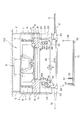
図1は、本発明の実施の形態に係る天井埋込型空気調和機100の斜視図であり、図2は天井埋込型空気調和機100の分解斜視図である。また、図3は天井埋込型空気調和機100の断面図である。
天井埋込型空気調和機100は、箱形に形成された板金製の本体ユニット1を有し、この本体ユニット1と、フィルタチャンバ20と、化粧パネル21とが三段に重ねられて構成されている。
本体ユニット1の外側面には複数の吊り金具1Bが設けられており、各々の吊り金具1Bには天井に固定された吊下ボルト2がナット4によって固定され、これらの吊下ボルト2を介して、天井埋込型空気調和機100は天井空間内に吊り下げ設置される。
Hereinafter, an embodiment of the present invention will be described with reference to the drawings.
FIG. 1 is a perspective view of a ceiling-embedded
The ceiling-embedded
A plurality of
図3に示すように、本体ユニット1の内部には、側板1A及び天面の内側に発泡スチロール製の断熱材3がほぼ全面にわたって配置されており、この断熱材3の内側に、送風機9、及び熱交換器11が収容されている。
送風機9は、シャフトを下向きに配置されたモータ5と、モータ5のシャフトに取り付けられたターボファン7とで構成されている。熱交換器11は、上面視で五角形に成形されたプレートフィン型の熱交換器であり、送風機9を取り囲むように配置される。
As shown in FIG. 3, inside the
The
熱交換器11の下方には、熱交換器11の下面11Aを覆うように、発泡スチロール樹脂等の合成樹脂製のドレンパン13が配設され、ドレンパン13に溜まるドレンを外部に排出するドレンポンプ(図示略)が設けられている。
ドレンパン13は、本体ユニット1の側板1Aの内面に接するように配設され、ドレンパン13の中央には吸込開口14が開口し、周縁部には熱交換器11を通った送風機9の排気を通すための吹出開口15が形成されている。吸込開口14の上部には、吸込開口14を通った被調和室の空気を送風機9に案内するノズル17が取り付けられている。また、ドレンパン13には天井埋込型空気調和機100の制御回路や電源回路等を収容した電装ボックス(図示略)等の各種部品がねじ止めされている。
Below the
The
フィルタチャンバ20は、ドレンパン13の直下に重ねて配設されており、フィルタチャンバ20にはドレンパン13の吹出開口15に連通する通風孔25と、吸込開口14に連通する吸込開口26とが形成されている。
フィルタチャンバ20の下面には、化粧パネル21が取り付けられ、化粧パネル21は、図3に示すように天井板10と略面一となっている。
化粧パネル21には、被調和室の空気を吸込む吸込口22と、熱交換器11を通った調和空気を被調和室に吹き出す吹出口23とが形成され、吸込口22はフィルタチャンバ20の吸込開口26に連通し、吹出口23はフィルタチャンバ20の通風孔25に連通する位置および形状に形成されている。
さらに、図1に示すように化粧パネル21の下面隅部にはインジケータ21Aが配置されている。インジケータ21Aは複数のLEDを備え、これらLEDの点灯状態(点灯、消灯、点滅)によって天井埋込型空気調和機100の動作状態を表示するとともに、各種の報知を行う。
The
A
The
Further, as shown in FIG. 1, an
また、化粧パネル21には、吸込口22に嵌合する吸込グリル30と、吸込グリル30を4本の吊紐36、37、38、39によって昇降自在に支持する昇降ユニット35とが取り付けられている。吸込グリル30の中央には室内空気を吸い込む吸込口31が形成され、吸込グリル30が吸込口22に嵌合した状態で吸込口31が吸込開口26に連通する。
The
昇降ユニット35は、化粧パネル21の内側、すなわちフィルタチャンバ20側の面に、板金製のステー(図示略)を介して取り付けられ、4本の吊紐36〜39を繰り出し、或いは巻き戻すことにより、所定の範囲で吸込グリル30を昇降させる。昇降ユニット35は、吸込グリル30とともに昇降手段として機能する。
吸込グリル30は、その一辺に2本の吊紐36、37が固定され、他辺に2本の吊紐38、39が固定されている。昇降ユニット35は、吊紐36〜39の繰り出し及び巻き戻しを行う昇降機構(図示略)と、昇降機構を制御する制御基板(図示略)とを、一つの筐体に収納したものである。
The lifting / lowering
The
吊紐36〜39は、その一端がそれぞれ吸込グリル30の裏面、すなわち図中上側の面に固定され、他端は、化粧パネル21の裏面に設けられたガイドによって水平方向に転向され、昇降ユニット35内に収容される。
昇降機構は、吊紐36〜39がそれぞれ巻き回されるボビン(図示略)、ボビンを回転させるギヤ(図示略)及びグリル昇降モータ37(図6)を内蔵し、このグリル昇降モータ37の正転或いは逆転動作によってボビンが正方向または逆方向に回転され、吊紐36〜39の繰り出し或いは巻き戻しが行われる。
吊紐36〜39が巻かれた各ボビンは、吸込グリル30をなるべく水平を保って昇降させるべく、各々の吊紐36〜39が一様に繰り出され、或いは巻き戻されるように、その径と回転量が設定されている。また、各ボビンは独立した軸により支持されていてもよいし、複数のボビンを同軸に支持され、同時に回転する構成としてもよい。
One end of each of the hanging straps 36 to 39 is fixed to the back surface of the
The lifting mechanism includes a bobbin (not shown) around which the hanging straps 36 to 39 are wound, a gear (not shown) for rotating the bobbin, and a grill lifting motor 37 (FIG. 6). The bobbin is rotated in the forward direction or the reverse direction by rolling or reversing operation, and the hanging straps 36 to 39 are fed out or rewound.
Each bobbin around which the hanging straps 36 to 39 are wound has a diameter and a diameter so that each of the hanging straps 36 to 39 is uniformly fed out or rewound in order to raise and lower the
このように構成される天井埋込型空気調和機100は、図示しない室外機から供給される冷媒を熱交換器11に通して、熱交換器11を蒸発器または凝縮器として機能させることにより、被調和室の室内空気を冷却または加熱する。すなわち、天井埋込型空気調和機100は、送風機9の動作によって吸込グリル30の吸込口31から室内空気を吸い込み、この室内空気は化粧パネル21の吸込口22、フィルタチャンバ20の吸込開口26、本体ユニット1の吸込開口14、及び、ノズル17を通って吸い上げられる。この室内空気は送風機9によって熱交換器11に送り込まれ、熱交換器11を通る際に冷却または加熱され、調和空気となる。そして、この調和空気は、本体ユニット1の吹出開口15からフィルタチャンバ20の通風孔25を通って下方に流れ、化粧パネル21の吹出口23から被調和室に吹き出され、被調和室を冷房または暖房する。
The ceiling-embedded
フィルタチャンバ20の吸込開口26には、ロールフィルタ40が配設されている。ロールフィルタ40は、送風機9によって吸込口31から吸い込まれた被調和室内の空気を通過させる際に、この吸込空気中に浮遊する塵埃を捕集するフィルタであり、室内空気が入る吸込口31側の面は、塵埃が付着する捕集面40Aとなる。
A
ロールフィルタ40の一端は、吸込開口26の一端側に配設された第1ロール41に巻かれており、他端は吸込開口26の他端側に配設された第2ロール42に巻かれている。ロールフィルタ40は、第1ロール41と第2ロール42との間で、吸込開口26の端に配設されたガイドローラ47、48に架け渡されている。ガイドローラ47、48は、それぞれ吸込開口26の端に極めて近い位置に配設されており、ガイドローラ47、48間に張られたロールフィルタ40は、吸込開口26のほぼ全面を覆っていて、このガイドローラ47、48間に吸込空気を通過させる。
第1ロール41、第2ロール42、及びガイドローラ47、48は、いずれも、吸込開口26の内壁面に直接またはステー等を介して、回転可能に取り付けられている。
One end of the
The
第1ロール41には使用前のロールフィルタ40が巻かれており、このロールフィルタ40が順次繰り出されて、フィルタとして使用される。ロールフィルタ40のうち、ガイドローラ47、48間に位置する部分が吸込空気を通すフィルタとして機能するので、このガイドローラ47、48間の距離に相当する長さを1回分とする。第1ロール41には1回分の使用量に比べて十分に長く、例えば数回〜数十回分の長さのロールフィルタ40が巻かれている。このため、天井埋込型空気調和機100の運転中に塵埃が捕集面40Aに付着した場合には、1回分の長さのロールフィルタ40を第2ロール42に巻き取り、巻き取り分に相当する長さを第1ロール41から繰り出すことによって、吸込開口26を覆うフィルタを全て新品に替えることができる。この動作によれば、第1ロール41と第2ロール42を回転させるだけで、古いフィルタを新品のフィルタに交換した場合と同様に、塵埃の捕集能力が回復する、通風抵抗が低下する等の効果が得られる。
A
第1ロール41の軸にはギヤ41Aが取り付けられ、このギヤ41Aには伝達ギヤ43が噛み合い、この伝達ギヤ43には第1巻取モータ45の回転軸に連結されたギヤ45Aが噛み合っている。一方、第2ロール42の軸にはギヤ42Aが取り付けられ、このギヤ42Aは伝達ギヤ44に噛み合い、伝達ギヤ44には、第2巻取モータ46の回転軸に連結されたギヤ46Aが噛み合っている。このため、第1巻取モータ45(巻取手段)の回転動作によって第1ロール41が回転し、第2巻取モータ46(巻取手段)の回転動作によって第2ロール42が回転する。
A
本実施形態では、ロールフィルタ40を第1ロール41から第2ロール42に向けて送る方向(図3中符号A)を順方向、第2ロール42から第1ロール41に向けて送る方向(図3中符号B)を逆方向とする。ロールフィルタ40を順方向に送る場合は第2巻取モータ46によって第2ロール42が回転され、ロールフィルタ40が第2ロール42に巻き取られる。一方、ロールフィルタ40を逆方向に送る場合は第1巻取モータ45によって第1ロール41が回され、ロールフィルタ40が第1ロール41に巻き取られる。
In the present embodiment, the direction in which the
そして、ガイドローラ47、48間には、ガイドローラ47側に寄った位置に、ブラシ51と押さえ板53とが配設されている。ブラシ51は、一面側に植毛され、この植毛面がロールフィルタ40の捕集面40Aに当接した状態で、捕集面40Aに付着している塵埃を掻き落とすブラシである。また、押さえ板53は、ロールフィルタ40を挟んでブラシ51に対向する位置にあって、ブラシ51とともにロールフィルタ40を挟み込む板状部材である。
ブラシ51及び押さえ板53は、いずれも、ロールフィルタ40の幅方向に延びる棒形状の部材であって、その両端は吸込開口26の壁面に支持されている。ブラシ51及び押さえ板53は、後述する移動ユニット50によって、ロールフィルタ40に近づく方向と、ロールフィルタ40から離れる方向とに移動させることが可能である。
A
The
図4は、天井埋込型空気調和機100の要部構成を示す拡大図であり、図4Aはブラシ51及び押さえ板53を移動させる移動ユニット50の構成を示す要部拡大側面図であり、図4Bはダストボックス57の取付状態を示す要部断面図である。
図4Aに示すように、移動ユニット50(移動手段)は、ブラシ51と押さえ板53とのほぼ中間位置に配設されたブラシ昇降ギヤ61と、ブラシ昇降モータ64の回転軸に取り付けられた駆動ギヤ63と、駆動ギヤ63の回転力をブラシ昇降ギヤ61に伝達する伝達ギヤ62と、を備えている。これらブラシ昇降ギヤ61、伝達ギヤ62及び駆動ギヤ63は、吸込開口26を構成するフィルタチャンバ20の壁面に、回転可能に支持されている。
4 is an enlarged view showing a main part configuration of the ceiling-embedded
As shown in FIG. 4A, the moving unit 50 (moving means) includes a brush lifting / lowering
また、ブラシ51の末端にはブラシ支持軸52が突出し、押さえ板53の末端には押さえ板支持軸54が突出している。これらブラシ支持軸52及び押さえ板支持軸54は、フィルタチャンバ20の壁面に固定された2本のガイド枠55によって側方から挟まれており、このガイド枠55に沿って、上下にスライド可能となっている。
A
ブラシ支持軸52には押さえ板53に向かって突出するラック56が取り付けられ、押さえ板支持軸54にはブラシ51に向かって突出するラック58が取り付けられており、これらのラック56、58はブラシ昇降ギヤ61に噛み合っている。このため、ブラシ昇降ギヤ61の回転によって、ラック56、58が上下に移動し、ブラシ51及び押さえ板53が同時に上昇または下降する。
図4Aに示す構成では、ブラシ昇降ギヤ61が、図中符号D1で示すように反時計回りに回転すると、ラック56が上昇し、ラック58が下降する。このため、ブラシ51と押さえ板53は互いに接近するように、図中矢印D3で示す向きに移動して、ロールフィルタ40を挟み込む。
これに対し、ブラシ昇降ギヤ61が、図中符号D2で示すように時計回りに回転すると、ラック56が下降する一方で、ラック58は上昇する。このため、ブラシ51と押さえ板53は互いに離隔するように、図中矢印D4で示す向きに移動して、ロールフィルタ40から離れる。
A
In the configuration shown in FIG. 4A, when the
On the other hand, when the brush raising / lowering
このように、移動ユニット50は、ブラシ昇降モータ64の動作によってブラシ51と押さえ板53とを、ロールフィルタ40に接近及び当接させ、或いは離隔させるように移動させる。このため、捕集面40Aの塵埃を掻き落とす必要がある場合にはブラシ51と押さえ板53とをロールフィルタ40に当接させ、それ以外の状態ではブラシ51と押さえ板53とをロールフィルタ40から離しておくことができる。
そして、移動ユニット50によってブラシ51と押さえ板53とがロールフィルタ40側に移動されると、ブラシ51が捕集面40Aに当接するとともに、ロールフィルタ40の裏側に押さえ板53が当接する。つまり、ロールフィルタ40はブラシ51と押さえ板53とに挟まれるため、ブラシ51が捕集面40Aに確実に接触し、捕集面40Aの塵埃を確実に掻き落とすことができ、捕集面40Aに強く付着した塵埃も除去できる。
In this way, the moving
When the
また、ブラシ51の下方には、ブラシ51によって捕集面40Aから掻き落とされた塵埃を捕集するダストボックス57が配設されている。ダストボックス57は上面が開口しており、ブラシ51の端から落下する塵埃を受けて蓄積する箱である。
図4Bに示すように、ダストボックス57は、吸込グリル30の上面に立設された2枚のリブ33に挟まれて支持される。ダストボックス57の側面にはボス59が設けられ、リブ33には、ボス59が嵌合する受け穴34が形成されていて、受け穴34にボス59がはまり込むことで、ダストボックス57が脱落しないよう支持されている。
ダストボックス57内に塵埃が溜まった場合には、ダストボックス57を吸込グリル30から取り外して、ダストボックス57内の塵埃を捨てることができる。この場合、ダストボックス57の上部の開口部の両端を、図4Bに矢印で示すように、リブ33から離れる方向に押圧して、受け穴34からボス59を離脱させることで、ダストボックス57を取り外すことができる。
A
As shown in FIG. 4B, the
When dust accumulates in the
また、ダストボックス57は吸込グリル30に支持されているため、昇降ユニット35の動作により吸込グリル30を下降させると、ダストボックス57は吸込グリル30とともに下降する。
図5は、天井埋込型空気調和機100において吸込グリル30を下降させた状態を示す断面図である。
この図5に示すように、吸込グリル30は、昇降ユニット35から繰り出される4本の吊紐36〜39により吊り下げられ、化粧パネル21から真下に下降する。このとき、吸込グリル30の裏面、すなわち上面のリブ33、33によって保持されているダストボックス57は、吸込グリル30とともに下降する。従って、ダストボックス57に塵埃が溜まった場合には、吸込グリル30を下降させて、上記のようにダストボックス57を取り外し、ゴミを捨て、必要に応じてダストボックス57を洗浄すればよい。
また、吸込グリル30にはロールフィルタ40を含む各部が搭載されず、ダストボックス57が取り付けられただけであるから、吸込グリル30を昇降させる際に昇降ユニット35に加わる重量負荷が小さくて済むという利点がある。
Further, since the
FIG. 5 is a cross-sectional view showing a state where the
As shown in FIG. 5, the
Further, since the
図6は、ロールフィルタ40の駆動に係る制御回路70の構成を示す機能ブロック図である。
この制御回路70は、各部を集中制御する制御回路70に、不揮発性メモリ72、モータドライバ73、センサ制御回路74、及び、通信部78を接続して構成される。
マイコン71は、図示しないメモリを内蔵し、このメモリに格納されたプログラムを読み出して実行することにより、制御回路70の各部を制御する。
不揮発性メモリ72は、EEPROMやフラッシュメモリにより構成され、マイコン71によってモータドライバ73やセンサ制御回路74を制御する際に必要な設定値等を記憶する。
モータドライバ73は、天井埋込型空気調和機100が備える第1巻取モータ45、第2巻取モータ46、ブラシ昇降モータ64、及びグリル昇降モータ37の各モータに接続されている。モータドライバ73は、これら各モータに対して、マイコン71の制御に従って駆動電流を供給し、各モータを駆動制御する。ここで、第1巻取モータ45、第2巻取モータ46、ブラシ昇降モータ64、及びグリル昇降モータ37のいずれかがステッピングモータで構成される場合、モータドライバ73は、当該モータに対して駆動パルスを出力して、必要量だけ当該モータを動作させる。
FIG. 6 is a functional block diagram showing the configuration of the
The
The
The
The
センサ制御回路74は、巻取位置センサ66、グリル位置センサ67、及びダストボックスセンサ68の各センサに接続されている。巻取位置センサ66は、第1ロール41及び第2ロール42のいずれか、或いは両方におけるロールフィルタ40の巻き取り量を検出するセンサである。巻取位置センサ66の検出値に基づいて、ロールフィルタ40が、第1ロール41と第2ロール42との各々に巻かれている量を求めることができる。巻取位置センサ66は、具体的には、第1ロール41及び第2ロール42の回転量を検出するロータリーエンコーダを用いて実現可能である。
グリル位置センサ67は、昇降ユニット35によってグリル昇降モータ37を上昇または下降させる際の吸込グリル30の位置を検出するセンサである。グリル位置センサ67は、具体的には、吊紐36〜39を巻き取るボビンの回転量を検出するロータリーエンコーダを用いて実現可能である。
The
The
ダストボックスセンサ68は、ダストボックス57に溜まった塵埃が所定量に達したことを検出するセンサであり、このダストボックスセンサ68の検出値に基づいて、ダストボックス57内のゴミを捨てる必要があるか否かを判別できる。ダストボックスセンサ68は、例えば、ダストボックス57が透明な箱で構成される場合に、このダストボックス57に光を透過させて透光量を検出することで塵埃の量を検出するセンサや、ダストボックス57の上端近傍における塵埃の有無を光学的に検出するセンサ、或いは、ダストボックス57の重量を検出するセンサ等により実現できる。
センサ制御回路74は、巻取位置センサ66、グリル位置センサ67及びダストボックスセンサ68の各々における検出値を予め設定された所定周期でサンプリングし、検出値を示すデジタルデータをマイコン71に出力する。
The
The
また、マイコン71は、通信部78により、天井埋込型空気調和機100を操作するリモコン80との間で無線通信を実行可能である。
リモコン80は、複数の操作子と、この操作子の操作により設定された内容を表示する液晶表示装置とを備え、当該操作子の操作に応じて、操作信号を通信部78に無線送信する。通信部78は、リモコン80から送信される操作信号を受信して、マイコン71に出力する。例えば、リモコン80が備える操作子によって吸込グリル30を下降させるよう指示された場合、マイコン71は、この操作を示す操作信号に応答して、モータドライバ73によってグリル昇降モータ37を正転動作させ、吸込グリル30を下降させる。ここで、マイコン71は、センサ制御回路74を介してグリル位置センサ67の検出値を取得し、吸込グリル30が所定位置まで下降したところでグリル昇降モータ37を停止させる。その後、リモコン80によって吸込グリル30を上昇させる指示が入力された場合、マイコン71は、この指示操作の操作信号に応答して、モータドライバ73によってグリル昇降モータ37を逆転動作させ、吸込グリル30を上昇させる。
Further, the
The
マイコン71は、センサ制御回路74から入力されるデータに基づいて、モータドライバ73を制御して各モータを動作させることで、ロールフィルタ40の巻き取り動作、ロールフィルタ40の清掃動作等を実行する。
また、マイコン71は、センサ制御回路74から入力されるデータに基づいて、ダストボックス57内の塵埃を捨てる必要があると判別した場合には、インジケータ21Aを所定の状態で点灯或いは点滅させることで、ゴミ捨てが必要である旨の報知を行う。
The
Further, when the
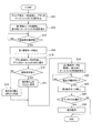
図7は、天井埋込型空気調和機100の動作を示すフローチャートであり、特に、ロールフィルタ40の駆動に係る動作を示す。
この図7に示す動作は、天井埋込型空気調和機100の空調運転時間が、予め設定された所定時間に達する毎に、実行される。
FIG. 7 is a flowchart showing the operation of the ceiling-embedded
The operation shown in FIG. 7 is executed each time the air conditioning operation time of the ceiling-embedded
制御回路70のマイコン71は、天井埋込型空気調和機100の空調運転の累積運転時間が所定時間に達する毎に、ロールフィルタ40の清掃を行うため、モータドライバ73を制御してブラシ昇降モータ64を動作させ、ブラシ51がロールフィルタ40の捕集面40Aに接するように、ブラシ51と押さえ板53とを移動させる(ステップS11)。
次に、マイコン71は、第1巻取モータ45を動作させて、ロールフィルタ40を第1ロール41に巻き取ることで、ロールフィルタ40を逆方向(図3の矢印B方向)に移動させる(ステップS12)。
この巻き取り動作によって、ロールフィルタ40のうち吸込口31からの吸込空気の塵埃を捕集した部分が、第1ロール41側に送られ、その途中でブラシ51によってロールフィルタ40の塵埃が掻き落とされる。
The
Next, the
As a result of this winding operation, the portion of the
ロールフィルタ40を第1ロール41に巻き取る動作の間、マイコン71は、巻取位置センサ66の検出値を監視し(ステップS13)、1回分に相当する長さだけロールフィルタ40を巻き取ると(ステップS13;Yes)、モータドライバ73を制御して第1巻取モータ45を停止させ(ステップS14)、ブラシ昇降モータ64を動作させて、ブラシ51を捕集面40Aから離れさせる(ステップS15)。これにより、ロールフィルタ40の動きが停止し、捕集面40Aからブラシ51が離れる。
During the operation of winding the
ここで、マイコン71は、第1ロール41に巻き取った部分のロールフィルタ40が再使用可能か否かを判別する(ステップS17)。ロールフィルタ40は、ブラシ51により塵埃を掻き落とすことで、同じ部分を、フィルタとして複数回使用でき、その使用回数の上限は予め設定されている。マイコン71は、ステップS12〜S13で巻き取った1回分のロールフィルタ40の累積使用回数と、使用可能な上限とを比較し、この1回分のロールフィルタ40が再使用できるか否かを判別する。
そして、再使用可能な場合には、巻き取り量を1回分に相当する長さに設定し(ステップS16)、巻き取った部分を再使用できない場合は巻き取り量として2回分(1回分の2倍)に相当する長さを設定する(ステップS18)。
巻き取り量が1回分に設定された場合、第1ロール41から1回分のロールフィルタ40が繰り出され、吸込口31の下流側に配置される。この場合、ブラシ51によって塵埃が書き取られた部分が再びフィルタとして使用される。これに対し、巻き取り量が2回分に設定された場合、第1ロール41から2回分のロールフィルタ40が繰り出される。すなわち、先にブラシ51によって塵埃が書き取られた部分は第2ロール42に巻き取られ、この部分に続く未使用の部分が、吸込口31の下流側に配置されてフィルタとして使用される。つまり、巻き取り量が2回分に設定された場合には、フィルタとして使用する部分が未使用品に交換されたに等しい。
Here, the
And when reusable, the amount of winding is set to the length equivalent to 1 time (step S16), and when the wound part cannot be reused, it is set as 2 times (2 for 1 time). Is set (step S18).
When the winding amount is set to one time, the
マイコン71は、モータドライバ73を制御して第2巻取モータ46を動作させることにより、ロールフィルタ40を第2ロール42に巻き取って、順方向(図3の矢印A方向)に移動させる(ステップS19)。この巻き取り動作中、マイコン71は、巻取位置センサ66の検出値を監視し(ステップS20)、設定された巻き取り量のロールフィルタ40が巻き取られるまで、巻き取り動作を継続させる。
設定された巻き取り量の巻き取りが完了した場合(ステップS20;Yes)、マイコン71は、モータドライバ73を制御して第2巻取モータ46を停止させ(ステップS21)、センサ制御回路74によって取得されるダストボックスセンサ68の検出値に基づいて、ダストボックス57内の塵埃が満杯か否かを判別する(ステップS22)。ここで、ダストボックス57が満杯であれば(ステップS22;Yes)、マイコン71は、インジケータ21Aによる報知を行い(ステップS23)、本処理を終了する。また、ダストボックスセンサ68の検出値から、ダストボックス57が満杯でないと判別した場合(ステップS22;No)、マイコン71は、そのまま本処理を終了する。
The
When winding of the set winding amount is completed (step S20; Yes), the
以上のように、本発明を適用した実施形態に係る天井埋込型空気調和機100によれば、ロールフィルタ40を第1巻取モータ45及び第2巻取モータ46によって繰り出し或いは巻き取ることにより、ロールフィルタ40の表面に当接するブラシ51によって、ロールフィルタ40の表面に付着した塵埃を容易に除去することができ、除去された塵埃が集積されるダストボックス57を昇降させることでダストボックス57内の塵埃を簡単に破棄できる。これにより、ロールフィルタ40のメンテナンスが容易で、ダストボックス57を昇降する際の負荷が非常に軽くて済む天井埋込型空気調和機100を実現できる。また、ロールフィルタ40に付着した塵埃を除去することで、長期間にわたって交換せず使用可能なロールフィルタ40の交換周期を、さらに長くすることができ、メンテナンスに係る労力を大幅に軽減できる。
As described above, according to the ceiling-embedded
また、吸込空気の塵埃を捕集したロールフィルタ40を巻き取りつつブラシ51によって塵埃を除去し、その後に、塵埃を除去した部分のロールフィルタ40を再び吸込口31と送風機9との間に繰り出す。このため、ロールフィルタ40の塵埃を除去して繰り返し使用できる。これにより、ロールフィルタ40の交換周期を大幅に延長することができ、メンテナンスに係る労力を軽減できる。
In addition, dust is removed by the
また、ブラシ51をロールフィルタ40の表面に接離可能に移動させる移動ユニット50を備え、ブラシ51をロールフィルタ40の表面に当接させて塵埃を除去し、その後、ブラシ51をロールフィルタ40の表面から離して、塵埃を除去した部分のロールフィルタ40を再び吸込口31と送風機9との間に繰り出す。これにより、第1巻取モータ45及び第2巻取モータ46の動力を利用してロールフィルタ40の表面から塵埃を効率よく除去できる。その一方で、単にロールフィルタ40を巻き取り或いは繰り出す場合にはロールフィルタ40にブラシ51が当接しないので、ロールフィルタ40を巻き取り或いは繰り出す動作を効率よく行うことができる。さらに、ブラシ51とロールフィルタ40との不要な接触を無くすことで、ブラシ51及びロールフィルタ40の耐久性の向上が期待できる。
Moreover, the moving
さらに、ロールフィルタ40において塵埃が付着する捕集面40Aに当接するブラシ51と、ロールフィルタ40を挟んでブラシ51に対向する押さえ板53とを備えているので、ロールフィルタ40の捕集面40Aの塵埃を、効率よく確実に除去できる。
また、フィルタチャンバ20に、ロールフィルタ40と、第1巻取モータ45及び第2巻取モータ46と、ブラシ51とを設け、吸込グリル30にダストボックス57のみを支持させたことで、吸込グリル30及び昇降ユニット35の負荷が軽く済む。
Further, since the
In addition, the
また、天井埋込型空気調和機100は、制御回路70が備えるマイコン71によって、モータドライバ73を介して第1巻取モータ45、第2巻取モータ46、及びブラシ昇降モータ64を制御するとともに、センサ制御回路74を介して巻取位置センサ66及びダストボックスセンサ68の検出値を取得して、ロールフィルタ40の巻き取り及びブラシ51と押さえ板53の移動を行うので、効率のよい制御を行い、各部を素早く動作させる。そして、マイコン71は、移動ユニット50によりブラシ51を捕集面40Aに当接させて、第1巻取モータ45を駆動してロールフィルタ40を巻き取って塵埃を除去し、続いてブラシ51を捕集面40Aから離隔させて第2巻取モータ46によってロールフィルタ40を巻き取ることで、ロールフィルタ40の同じ部分を何度も利用するので、ロールフィルタ40の交換周期を延長し、メンテナンスの頻度を大幅に低下させることができる。ロールフィルタ40の交換時期が来るまでの間、ユーザは、マイコン71の制御によるインジケータ21Aの報知動作を見て、リモコン80の操作によって吸込グリル30を降下させ、ダストボックス57内の塵埃を捨てるだけでよく、少ない労力で簡単なメンテナンスを行うだけで、塵埃によるロールフィルタ40の目詰まり、及び、これに起因する運転効率の低下等を回避して、快適に天井埋込型空気調和機100を使用できる。
The ceiling-embedded
以上、本発明の一実施形態について説明したが、本発明はこれに限定されるものではなく、種々の変更実施が可能である。例えば、上記実施形態において、ダストボックス57が吸込グリル30の裏面に設けられたリブ33によって保持される構成を例に挙げて説明したが、本発明はこれに限定されるものではなく、ネジ等により固定されてもよいし、クリップ等により着脱可能に固定されていてもよい。また、ブラシ51により捕集面40Aから掻き落とされた塵埃をダストボックス57の上面に案内するガイドを、ブラシ51の下方に設けてもよい。さらに、ダストボックス57を昇降させる機構の具体的な構成も任意であって、4本の吊紐36〜39により吸込グリル30全体を昇降させる構成のほか、吸込グリル30の一部のみが昇降する構成としてもよく、この場合、吊紐の数は任意である。また、ロールフィルタ40の塵埃を除去する構成はブラシ51に限らず、回転式のブラシを用いることも可能であるし、第1ロール41及び第2ロール42を回転させる構成についても、伝達ギヤ43、44、第1巻取モータ45及び第2巻取モータ46を用いた機構に限定されず、例えばモータによって第1ロール41及び第2ロール42の軸を直接駆動してもよく、移動ユニット50の具体的な構成も任意である。
さらに、本発明を適用した空気調和機は天井埋込型空気調和機100に限らず、天井吊下型の空気調和機にも適用可能であり、その他の具体的態様も任意に変更可能である。
As mentioned above, although one Embodiment of this invention was described, this invention is not limited to this, A various change implementation is possible. For example, in the above-described embodiment, the
Furthermore, the air conditioner to which the present invention is applied is not limited to the ceiling-embedded
1 本体ユニット
9 送風機
11 熱交換器
13 ドレンパン
20 フィルタチャンバ
21 化粧パネル
22 吸込口
26 吸込開口
30 吸込グリル(昇降手段)
31 吸込口
33 リブ
34 受け穴
35 昇降ユニット(昇降手段)
40 ロールフィルタ
40A 捕集面
41 第1ロール
42 第2ロール
45 第1巻取モータ(巻取手段)
46 第2巻取モータ(巻取手段)
47、48 ガイドローラ
50 移動ユニット(移動手段)
51 ブラシ
53 押さえ板
57 ダストボックス
64 ブラシ昇降モータ
70 制御回路
71 マイコン
100 天井埋込型空気調和機
DESCRIPTION OF
31
40
46 Second winding motor (winding means)
47, 48
51
Claims (5)
前記吸込口内の一方側においてロール状に巻き回され、前記吸込口と前記送風機との間に繰り出されて前記吸込口からの吸込空気の塵埃を捕集するロールフィルタと、前記ロールフィルタを繰り出し或いは巻き取る巻取手段とを設け、
前記ロールフィルタの表面に当接して前記ロールフィルタの塵埃を除去する除去手段と、前記除去手段により前記ロールフィルタから除去された塵埃が当該除去手段から移されて集積されるダストボックスとを備え、さらに、前記ダストボックスを、前記ロールフィルタ及び前記除去手段に対して昇降可能に支持する昇降手段を備えたこと、
を特徴とする空気調和機。 In an air conditioner including a main body unit having a heat exchanger and a blower, and a decorative panel that is disposed below the main body unit and has a suction port for sucking air in a conditioned room,
A roll filter wound around in one side of the suction port and drawn out between the suction port and the blower to collect dust from the suction air from the suction port; A winding means for winding,
A removing unit that contacts the surface of the roll filter and removes dust from the roll filter; and a dust box in which the dust removed from the roll filter by the removing unit is transferred from the removing unit and accumulated. And a lifting means for supporting the dust box so as to be lifted and lowered relative to the roll filter and the removing means,
Air conditioner characterized by.
を特徴とする請求項1記載の空気調和機。 The roll filter, which has collected dust from the intake air from the suction port, is wound by the removing means while being wound from one side of the suction port to the other or the other side between the suction port and the blower by the winding means. Removing the dust, and then feeding out the part of the roll filter from which the dust has been removed again between the suction port and the blower,
The air conditioner according to claim 1.
前記移動手段によって前記除去手段を前記ロールフィルタの表面に当接させて、前記ロールフィルタを前記巻取手段によって前記吸込口内の一方側或いは他方側に巻き取ることで前記除去手段によって塵埃を除去し、その後、前記移動手段によって前記除去手段を前記ロールフィルタの表面から離間させてから塵埃を除去した部分の前記ロールフィルタを再び前記吸込口と前記送風機との間に繰り出すこと、
を特徴とする請求項2記載の空気調和機。 A moving means for moving the removing means so as to come in contact with and separate from the surface of the roll filter;
The removing means is brought into contact with the surface of the roll filter by the moving means, and dust is removed by the removing means by winding the roll filter to one side or the other side in the suction port by the winding means. Then, the part of the roll filter from which the dust is removed after separating the removing unit from the surface of the roll filter by the moving unit is again fed between the suction port and the blower,
The air conditioner according to claim 2.
を特徴とする請求項1から3のいずれかに記載の空気調和機。 The removing means is a brush that contacts the surface of the roll filter on which dust adheres, and has a pressing plate at a position facing the brush across the roll filter;
The air conditioner according to any one of claims 1 to 3.
を特徴とする請求項1から4のいずれかに記載の空気調和機。 A filter chamber is provided between the main unit and the decorative panel, and the roll filter, the winding unit, and the removing unit are provided in the filter chamber.
The air conditioner according to any one of claims 1 to 4.
Priority Applications (1)
| Application Number | Priority Date | Filing Date | Title |
|---|---|---|---|
| JP2008207828A JP5283448B2 (en) | 2008-08-12 | 2008-08-12 | Air conditioner |
Applications Claiming Priority (1)
| Application Number | Priority Date | Filing Date | Title |
|---|---|---|---|
| JP2008207828A JP5283448B2 (en) | 2008-08-12 | 2008-08-12 | Air conditioner |
Publications (2)
| Publication Number | Publication Date |
|---|---|
| JP2010043786A true JP2010043786A (en) | 2010-02-25 |
| JP5283448B2 JP5283448B2 (en) | 2013-09-04 |
Family
ID=42015310
Family Applications (1)
| Application Number | Title | Priority Date | Filing Date |
|---|---|---|---|
| JP2008207828A Expired - Fee Related JP5283448B2 (en) | 2008-08-12 | 2008-08-12 | Air conditioner |
Country Status (1)
| Country | Link |
|---|---|
| JP (1) | JP5283448B2 (en) |
Cited By (5)
| Publication number | Priority date | Publication date | Assignee | Title |
|---|---|---|---|---|
| JP2011016433A (en) * | 2009-07-08 | 2011-01-27 | East Japan Railway Co | Roll filter unit for railroad vehicle |
| KR20110116864A (en) * | 2010-04-20 | 2011-10-26 | 엘지전자 주식회사 | Air conditioner |
| KR101201234B1 (en) | 2010-07-22 | 2012-11-14 | 주식회사 성창에어텍 | Air cleaner for vehicles |
| KR20140100017A (en) * | 2013-02-05 | 2014-08-14 | 엘지전자 주식회사 | An air-conditioner and a controlling method thereof |
| CN105066399A (en) * | 2015-09-02 | 2015-11-18 | 珠海格力电器股份有限公司 | Lifting type panel grating installation structure and air conditioner |
Citations (10)
| Publication number | Priority date | Publication date | Assignee | Title |
|---|---|---|---|---|
| JPS63104913U (en) * | 1986-12-26 | 1988-07-07 | ||
| JP2001021205A (en) * | 1999-07-12 | 2001-01-26 | Sanyo Electric Co Ltd | Air conditioning apparatus |
| JP2007040689A (en) * | 2005-07-04 | 2007-02-15 | Mitsubishi Heavy Ind Ltd | Indoor unit and air conditioner |
| JP2007225171A (en) * | 2006-02-22 | 2007-09-06 | Mitsubishi Heavy Ind Ltd | Indoor unit and air conditioner |
| JP2007271174A (en) * | 2006-03-31 | 2007-10-18 | Fujitsu General Ltd | Ceiling embedded type air conditioner |
| JP2007285629A (en) * | 2006-04-18 | 2007-11-01 | Daikin Ind Ltd | Indoor unit for air conditioning system |
| JP2007309584A (en) * | 2006-05-18 | 2007-11-29 | Toshiba Kyaria Kk | Air conditioner |
| JP2008173616A (en) * | 2007-01-22 | 2008-07-31 | Kowa Co Ltd | Cleaning tool and air conditioner |
| JP2008196755A (en) * | 2007-02-09 | 2008-08-28 | Daikin Ind Ltd | Indoor unit of air conditioning device |
| JP2009264659A (en) * | 2008-04-24 | 2009-11-12 | Mitsubishi Heavy Ind Ltd | Indoor unit and air conditioner |
-
2008
- 2008-08-12 JP JP2008207828A patent/JP5283448B2/en not_active Expired - Fee Related
Patent Citations (10)
| Publication number | Priority date | Publication date | Assignee | Title |
|---|---|---|---|---|
| JPS63104913U (en) * | 1986-12-26 | 1988-07-07 | ||
| JP2001021205A (en) * | 1999-07-12 | 2001-01-26 | Sanyo Electric Co Ltd | Air conditioning apparatus |
| JP2007040689A (en) * | 2005-07-04 | 2007-02-15 | Mitsubishi Heavy Ind Ltd | Indoor unit and air conditioner |
| JP2007225171A (en) * | 2006-02-22 | 2007-09-06 | Mitsubishi Heavy Ind Ltd | Indoor unit and air conditioner |
| JP2007271174A (en) * | 2006-03-31 | 2007-10-18 | Fujitsu General Ltd | Ceiling embedded type air conditioner |
| JP2007285629A (en) * | 2006-04-18 | 2007-11-01 | Daikin Ind Ltd | Indoor unit for air conditioning system |
| JP2007309584A (en) * | 2006-05-18 | 2007-11-29 | Toshiba Kyaria Kk | Air conditioner |
| JP2008173616A (en) * | 2007-01-22 | 2008-07-31 | Kowa Co Ltd | Cleaning tool and air conditioner |
| JP2008196755A (en) * | 2007-02-09 | 2008-08-28 | Daikin Ind Ltd | Indoor unit of air conditioning device |
| JP2009264659A (en) * | 2008-04-24 | 2009-11-12 | Mitsubishi Heavy Ind Ltd | Indoor unit and air conditioner |
Cited By (7)
| Publication number | Priority date | Publication date | Assignee | Title |
|---|---|---|---|---|
| JP2011016433A (en) * | 2009-07-08 | 2011-01-27 | East Japan Railway Co | Roll filter unit for railroad vehicle |
| KR20110116864A (en) * | 2010-04-20 | 2011-10-26 | 엘지전자 주식회사 | Air conditioner |
| KR101633789B1 (en) * | 2010-04-20 | 2016-06-27 | 엘지전자 주식회사 | Air conditioner |
| KR101201234B1 (en) | 2010-07-22 | 2012-11-14 | 주식회사 성창에어텍 | Air cleaner for vehicles |
| KR20140100017A (en) * | 2013-02-05 | 2014-08-14 | 엘지전자 주식회사 | An air-conditioner and a controlling method thereof |
| KR102034300B1 (en) * | 2013-02-05 | 2019-10-18 | 엘지전자 주식회사 | An air-conditioner and a controlling method thereof |
| CN105066399A (en) * | 2015-09-02 | 2015-11-18 | 珠海格力电器股份有限公司 | Lifting type panel grating installation structure and air conditioner |
Also Published As
| Publication number | Publication date |
|---|---|
| JP5283448B2 (en) | 2013-09-04 |
Similar Documents
| Publication | Publication Date | Title |
|---|---|---|
| JP5283448B2 (en) | Air conditioner | |
| JP4840565B2 (en) | Air conditioner | |
| KR20140100017A (en) | An air-conditioner and a controlling method thereof | |
| JP2010032194A (en) | Ceiling-embedded air conditioner | |
| JP5327081B2 (en) | Automatic filter cleaning device and air conditioner | |
| JP2010043781A (en) | Air conditioner | |
| JP2005083721A (en) | Air conditioner | |
| JP2010096499A (en) | Indoor unit and air conditioner | |
| JPH05106859A (en) | Indoor unit of air conditioner | |
| KR20080058732A (en) | Air conditioner and the control method for the same | |
| JP4040433B2 (en) | Air conditioner indoor unit | |
| JP2010243030A (en) | Air supply ventilation device | |
| JP2005172362A (en) | Air conditioner | |
| JP5800496B2 (en) | Air conditioner indoor unit | |
| JP5911310B2 (en) | Air conditioner indoor unit | |
| JP2018096634A (en) | Blower device | |
| JP2010043783A (en) | Ceiling-recessed air conditioning device | |
| JP2010071502A (en) | Air conditioner | |
| JP5305808B2 (en) | Air conditioner | |
| WO2019038837A1 (en) | Air conditioner and notification method | |
| KR101633789B1 (en) | Air conditioner | |
| JP2007309583A (en) | Ceiling-embedded air conditioner | |
| JP5329166B2 (en) | Air conditioner | |
| KR20090044786A (en) | Air conditioner | |
| JP5356041B2 (en) | Air conditioner |
Legal Events
| Date | Code | Title | Description |
|---|---|---|---|
| A621 | Written request for application examination |
Free format text: JAPANESE INTERMEDIATE CODE: A621 Effective date: 20110801 |
|
| A977 | Report on retrieval |
Free format text: JAPANESE INTERMEDIATE CODE: A971007 Effective date: 20121011 |
|
| A131 | Notification of reasons for refusal |
Free format text: JAPANESE INTERMEDIATE CODE: A131 Effective date: 20121016 |
|
| A521 | Request for written amendment filed |
Free format text: JAPANESE INTERMEDIATE CODE: A523 Effective date: 20121213 |
|
| RD02 | Notification of acceptance of power of attorney |
Free format text: JAPANESE INTERMEDIATE CODE: A7422 Effective date: 20121213 |
|
| TRDD | Decision of grant or rejection written | ||
| A01 | Written decision to grant a patent or to grant a registration (utility model) |
Free format text: JAPANESE INTERMEDIATE CODE: A01 Effective date: 20130430 |
|
| A61 | First payment of annual fees (during grant procedure) |
Free format text: JAPANESE INTERMEDIATE CODE: A61 Effective date: 20130528 |
|
| R151 | Written notification of patent or utility model registration |
Ref document number: 5283448 Country of ref document: JP Free format text: JAPANESE INTERMEDIATE CODE: R151 |
|
| LAPS | Cancellation because of no payment of annual fees |