JP2010043705A - Joint for flexible tube - Google Patents
Joint for flexible tube Download PDFInfo
- Publication number
- JP2010043705A JP2010043705A JP2008208417A JP2008208417A JP2010043705A JP 2010043705 A JP2010043705 A JP 2010043705A JP 2008208417 A JP2008208417 A JP 2008208417A JP 2008208417 A JP2008208417 A JP 2008208417A JP 2010043705 A JP2010043705 A JP 2010043705A
- Authority
- JP
- Japan
- Prior art keywords
- flexible
- flexible tube
- joint
- tube
- sealing material
- Prior art date
- Legal status (The legal status is an assumption and is not a legal conclusion. Google has not performed a legal analysis and makes no representation as to the accuracy of the status listed.)
- Granted
Links
- 230000002093 peripheral effect Effects 0.000 claims abstract description 15
- 238000003780 insertion Methods 0.000 claims description 36
- 230000037431 insertion Effects 0.000 claims description 36
- 239000003566 sealing material Substances 0.000 claims description 28
- 239000000463 material Substances 0.000 abstract description 12
- 239000012530 fluid Substances 0.000 abstract description 5
- 238000007789 sealing Methods 0.000 abstract description 2
- 230000035515 penetration Effects 0.000 abstract 4
- 238000012856 packing Methods 0.000 description 12
- 230000004048 modification Effects 0.000 description 6
- 238000012986 modification Methods 0.000 description 6
- 210000000078 claw Anatomy 0.000 description 5
- 230000007246 mechanism Effects 0.000 description 4
- 230000008878 coupling Effects 0.000 description 3
- 238000010168 coupling process Methods 0.000 description 3
- 238000005859 coupling reaction Methods 0.000 description 3
- 229920001971 elastomer Polymers 0.000 description 3
- 239000005060 rubber Substances 0.000 description 3
- 229920003002 synthetic resin Polymers 0.000 description 3
- 239000000057 synthetic resin Substances 0.000 description 3
- 229920002943 EPDM rubber Polymers 0.000 description 2
- 229920000459 Nitrile rubber Polymers 0.000 description 2
- 230000000694 effects Effects 0.000 description 2
- 230000005489 elastic deformation Effects 0.000 description 2
- 229920003048 styrene butadiene rubber Polymers 0.000 description 2
- 229920000181 Ethylene propylene rubber Polymers 0.000 description 1
- 239000002174 Styrene-butadiene Substances 0.000 description 1
- BZHJMEDXRYGGRV-UHFFFAOYSA-N Vinyl chloride Chemical compound ClC=C BZHJMEDXRYGGRV-UHFFFAOYSA-N 0.000 description 1
- 230000004308 accommodation Effects 0.000 description 1
- 238000006243 chemical reaction Methods 0.000 description 1
- 239000002184 metal Substances 0.000 description 1
- 230000002265 prevention Effects 0.000 description 1
- 230000007480 spreading Effects 0.000 description 1
Images


Abstract
Description
本発明は、流体漏れが生じにくいフレキシブル管用継手に関する。 The present invention relates to a joint for flexible pipes that hardly causes fluid leakage.
特許文献1は、図9に示すようなフレキシブル管用継手を開示する。このフレキシブル管用継手は、継手本体200と、スリーブ202と、リングスプリング204と、Oリング206と、パッキン208と、押輪210と、を具備する。
Patent Document 1 discloses a joint for flexible pipe as shown in FIG. This flexible pipe joint includes a
継手本体200には、大径孔200aと中径孔200bと小径孔200cとが入口側より順に形成されている。スリーブ202は、継手本体200の中径孔200bに摺動自在に装着され、フレキシブル管300の先端部分と係合する。スリーブ202の入口側は継手本体200の大径孔200aにまで延びている。リングスプリング204は、環状に形成され、弾性変形によって拡縮し、荷重がかかっていない状態においてフレキシブル管300の谷部312外周に嵌入され、拡径した状態においててスリーブ202の入口側外面に装着される。押輪210は、継手本体200の入口側にOリング206を介して螺着されている。押輪210の内周面にはパッキン208が装着されている。押輪210の内奥端付近の内周面は、谷部312外周にリングスプリング204が嵌入したときのそのリングスプリング204の外径よりも小径に形成されている。
A
しかしながら、特許文献1に開示されたフレキシブル管用継手では、流体漏れが生じやすいという問題があった。 However, the flexible pipe joint disclosed in Patent Document 1 has a problem that fluid leakage is likely to occur.
本発明は、このような問題点を解消するためになされたものであり、その目的とするところは、流体漏れが生じにくいフレキシブル管用継手を提供することにある。 The present invention has been made to solve such problems, and an object of the present invention is to provide a joint for flexible pipes that is less likely to cause fluid leakage.
上記目的を達成するために、本発明のある局面に従うと、フレキシブル管用継手10は、継手本体20と、継手本体20内に収容される弾性変形可能なシール材22とを備える。フレキシブル管300は、継手本体20内に挿入される。フレキシブル管300の外周部には、円周方向全周に延びる山部310と谷部312とが管軸方向へ交互に並設されている。シール材22には中央に管挿入孔60が形成されている。その管挿入孔60にフレキシブル管300が挿入される。シール材22は、管挿入孔60に挿入されたフレキシブル管300の外周面と継手本体20の内周面との間でシールする。シール材22の内周側に、フレキシブル管300の外周面に対向する凸部50を有しており、凸部50は、シール材22の管挿入孔60内にフレキシブル管300を挿入することによって、フレキシブル管300の山部310を乗り越えて、フレキシブル管300の谷部312にかみあう。
In order to achieve the above object, according to one aspect of the present invention, the
本発明によれば、流体漏れを生じにくくできる。 According to the present invention, it is difficult to cause fluid leakage.
以下、図面を参照しつつ、本発明の実施の形態について説明する。以下の説明では、同一の部品には同一の符号を付してある。それらの名称および機能も同一である。したがって、それらについての詳細な説明は繰返さない。 Hereinafter, embodiments of the present invention will be described with reference to the drawings. In the following description, the same parts are denoted by the same reference numerals. Their names and functions are also the same. Therefore, detailed description thereof will not be repeated.
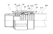
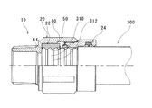
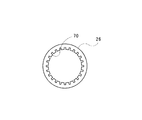
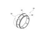
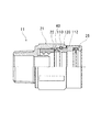
図1は、本発明の実施形態にかかるフレキシブル管用継手10を、フレキシブル管300差込み前の状態で示す半欠截断面図である。図2は、フレキシブル管300差込み途中の状態で示す同フレキシブル管用継手10の半欠截断面図である。図3は、フレキシブル管300の差込み完了後の状態で示す同フレキシブル管用継手10の半欠截断面図である。図4は、フレキシブル管300に引抜力がかかったときの同フレキシブル管用継手10の半欠截断面図である。図5は、本発明の実施形態にかかる突起つきリング26の平面図である。図6は、本発明の実施形態にかかる支え部材28の斜視図である。
FIG. 1 is a half-broken cross-sectional view showing a
図1に示すように、本実施例に係るフレキシブル管用継手10は、継手本体20と、シール材22と、押輪24と、突起つきリング26と、支え部材28と、リング30とを備える。
As shown in FIG. 1, the
継手本体20の一端部には、挿入口40が形成されている。継手本体20の他端部の外周には、接続用雄ねじ48が形成されている。挿入口40は、金属製のフレキシブル管300の先端部が挿入される部分である。シール材22は、この継手本体20内に収容される。押輪24は挿入口40の内部にねじ止めされる。押輪24は、管挿入用孔36を有している。突起つきリング26と、支え部材28と、リング30とは、継手本体20の挿入口40の内部に収容される。
An
フレキシブル管300は、図2に示すように、外周部に円周方向全周に延びる山部310と谷部312とを管軸方向へ交互に並設し、その外周を塩化ビニールなどの合成樹脂層314で被覆したものである。
As shown in FIG. 2, the
図1に示すように、継手本体20の挿入口40の奥には、収容部42が設けられている。シール材22は、この収容部42の中に収容される。収容部42の中において、シール材22は、継手本体20の軸方向に移動できる。収容部42の奥にはストッパー部44が設けられている。ストッパー部44の中心に、カラー46が設けられている。フレキシブル管300が継手本体20の中に挿入され、その先端がストッパー部44に達すると、カラー46の先端はフレキシブル管300の中に嵌まり込む。
As shown in FIG. 1, an
本実施形態において、シール材22はゴム製の円筒である。シール材22の素材として用いられるゴムの例には、NBR(Acrylonitrile-Butadiene Rubber)、SBR(Styrene-butadiene rubber)、EPDM(ethylene propylene rubber)などがある。シール材22の内周面には凸部50が設けられている。
In the present embodiment, the
図5に示すように、突起つきリング26は、内周に突起70が設けられた座金状の部材である。突起つきリング26の内周をフレキシブル管300が通過するとき、突起70は、フレキシブル管300の山部310によって押し広げられる。その山部310が突起つきリング26の内周を通過すると、突起70は山部310が通過する前の状態に戻る。
As shown in FIG. 5, the
図6に示すように、支え部材28は、リング部80と複数の爪82とを有する。爪82は、リング部80と一体となるように形成されている。上述したリング30は、爪82の先端の段部92に嵌まり込み、爪82が広がるのを防ぐ。なお、突起つきリング26と支え部材28とによって、フレキシブル管300が引き抜かれるのを防止する抜止機構が構成されている。抜止機構による引抜防止の仕組みについては後述する。
As shown in FIG. 6, the
図1に示すように、押輪24はパッキン溝90を有する。パッキン溝90は、押輪24の入口側の端の内周に設けられている。パッキン溝90は、円周方向に形成されている。パッキン溝90には、防水パッキン100が嵌め込まれている。防水パッキン100は、EPDMなどで作られている。防水パッキン100の断面はT形状である。
As shown in FIG. 1, the
次に、上述したフレキシブル管用継手10にフレキシブル管300を接続する要領について図1〜図3を参照しつつ説明する。
Next, the point which connects the
継手本体20には、シール材22と、突起つきリング26と、支え部材28と、リング30とが予め収容されており、かつ、継手本体20の挿入口40には、押輪24がねじ止めされている。
In the
フレキシブル管300の接続に際しては、先ずフレキシブル管300(このフレキシブル管300の合成樹脂層314は予め剥離されている。その結果、このフレキシブル管300の山部310が6個分ほど露出している。)を、押輪24の管挿入用孔36を通じて継手本体20の挿入口40内に差し込む。押輪24の中を通過したフレキシブル管300の先端は、支え部材28の内周を通過した後、突起つきリング26の突起70に接触する。
When connecting the
突起70に接触したフレキシブル管300の先端は、そのまま突起70を押す。このとき、シール材22と突起つきリング26とは収容部42の軸方向に移動する。その後、シール材22の一端がストッパー部44に当たると、突起つきリング26の突起70は、フレキシブル管300の先端により押し広げられる。シール材22はストッパー部44によって動きが制限されている。支え部材28にはそのような制限がかかっていない。これにより、支え部材28は、継手本体20の軸方向へは自由に移動できる。支え部材28が移動できるので、突起つきリング26が変形するためのスペースは十分にある。その結果、差し込むだけでフレキシブル管300をフレキシブル管用継手10に接続することが可能となる。図2はこの時点の状況を示す。
The tip of the
突起つきリング26の突起70がフレキシブル管300の先端により押し広げられると、フレキシブル管300の先端は、突起つきリング26を通過してシール材22の管挿入孔60内に進入する。シール材22の凸部50は、シール材22の管挿入孔60内にフレキシブル管300が挿入されると、フレキシブル管300の山部310を乗り越えて、フレキシブル管300の谷部312にかみあう。その後、フレキシブル管300の先端がストッパー部44に突き当たるまで、シール材22の凸部50は、フレキシブル管300の山部310を乗り越えることと、フレキシブル管300の谷部312にかみ合うこととを繰り返す。フレキシブル管300の先端がストッパー部44に突き当たると、フレキシブル管300の差込みは完了である。図3は、この状況を示す。
When the
フレキシブル管300の差込み完了後に、フレキシブル管300に対して引抜力がかかったとする。この場合、フレキシブル管300はその引抜力の方向に少し動く。凸部50が谷部312にかみ合っているので、シール材22も同様に動く。シール材22に押され、突起つきリング26も同様に動く。支え部材28は、突起つきリング26に押されて動いた後、押輪24の先端部にあたる。これにより、シール材22と、突起つきリング26と、支え部材28とは、それ以上動けなくなる。図4は、この状況を示す。
Assume that a pulling force is applied to the
この状態でさらに引抜力がかかったとすると、突起つきリング26の突起70はフレキシブル管300の山部310から力を受ける。これに対し、突起70は、支え部材28から反力を受けるので、フレキシブル管300が継手本体20に挿入されたときのように広がらない。突起70は、谷部312に嵌ったままである。その結果、フレキシブル管300はフレキシブル管用継手10から抜けない。
If further pulling force is applied in this state, the
今回開示された実施形態はすべての点で例示である。本発明の範囲は上述した実施形態に基づいて制限されるものではなく、本発明の趣旨を逸脱しない範囲で種々の設計変更をしてもよいのはもちろんである。 The embodiments disclosed herein are illustrative in all respects. The scope of the present invention is not limited based on the above-described embodiment, and various design changes may be made without departing from the spirit of the present invention.
たとえば、本発明は、継手本体20の一端に挿入口40が形成され、継手本体20の他端の外周に接続用雄ねじ48が形成された雄ねじフレキシブル管用継手に限られない。本発明は、他の構造、例えば、両端に受口部を有する左右対称のソケット形のフレキシブル管用継手や、エルボ型のフレキシブル管用継手などにも適用できることは勿論である。
For example, the present invention is not limited to the male threaded flexible pipe joint in which the
また、本発明は、フレキシブル管300の谷部312のうち2箇所をシール材がシールするものに限定されない。シール材のうち、フレキシブル管300の谷部312に密着する部分は、1箇所のみであってもよく、3箇所以上あってもよい。
Further, the present invention is not limited to the case where the sealing material seals two portions of the
また、凸部50の間隔は、フレキシブル管300の谷部312の間隔より小さくても良い。凸部50の間隔は、フレキシブル管300の谷部312にかみ合う際、弾性変形によって広がるためである。
Further, the interval between the
また、抜止機構は、上述した形態のものに限られない。 Further, the retaining mechanism is not limited to the one described above.
また、押輪は、挿入口40の内部にねじ止めされるものに限られない。図7は、本発明の第1の変形例にかかるフレキシブル管用継手11を、フレキシブル管差込み前の状態で示す半欠截断面図である。本変形例にかかるフレキシブル管用継手11は、上述した継手本体20と押輪24とに代えて、継手本体21と押輪25とを備える。継手本体21は、スナップリング係合溝110を有する。スナップリング係合溝110は、挿入口40の内周に形成されている。押輪21は、スナップリング収容溝112を有する。スナップリング収容溝112は、押輪21のうち、挿入口40に挿入する部分の外周に形成されている。押輪25は、スナップリング120によって継手本体21に固定されている。スナップリング120の外周がスナップリング係合溝110に嵌まり込んでおり、スナップリング120の内周がスナップリング収容溝112に嵌まり込んでいる。その他の点は、上述した継手本体20および押輪24と同様である。このような構造であっても、上述したフレキシブル管用継手10と同様の効果を得ることができる。
Further, the push wheel is not limited to one that is screwed into the
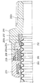
また、押輪は、必ずしも必要なものではない。図8は、本発明の第2の変形例にかかるフレキシブル管用継手12を、フレキシブル管差込み前の状態で示す半欠截断面図である。本変形例にかかるフレキシブル管用継手12は、継手本体32と、シール材22と、リテーナ33と、抜け止め防止材34とを備える。シール材22と、リテーナ33と、抜け止め防止材34とは、弾性係数が互いに異なるゴムでできている。このフレキシブル管用継手12にフレキシブル管300を挿入する際には、シール材22がストッパー部の方向へスライドする。それに伴い、リテーナ33もストッパー部の方向へスライドする。これにより、抜け止め防止材34の周囲には隙間ができるので、抜け止め防止材34はその外径および内径を拡げることができる。これにより、フレキシブル管用継手12にフレキシブル管300を挿入することが可能である。これに対し、フレキシブル管用継手12からフレキシブル管300を引き抜こうとしたときには、抜け止め防止材34は継手本体32の内壁に押し付けられる。これにより、抜け止め防止材34の内周はフレキシブル管300に食い込む。これにより、フレキシブル管300が抜けることは防止される。なお、フレキシブル管300の外周と継手本体32の内周とをシールするための原理は上述した実施形態と同様である。このような構造であっても、上述したフレキシブル管用継手10と同様の効果を得ることができる。
Further, the push wheel is not always necessary. FIG. 8 is a half-broken cross-sectional view showing the flexible pipe joint 12 according to the second modification of the present invention in a state before the flexible pipe is inserted. The flexible pipe joint 12 according to this modification includes a
10,11,12 フレキシブル管用継手
20,21,32,200 継手本体
22 シール材
24,25,210 押輪
26 突起つきリング
28 支え部材
30,206 リング
33 リテーナ
34 抜け止め防止材
36 管挿入用孔
40 挿入口
42 収容部
44 ストッパー部
46 カラー
48 雄ねじ
50 凸部
60 管挿入孔
70 突起
80 リング部
82 爪
90 パッキン溝
92 段部
100 防水パッキン
110 スナップリング係合溝
112 スナップリング収容溝
120 スナップリング
200a 大径孔
200b 中径孔
200c 小径孔
202 スリーブ
204 リングスプリング
208 パッキン
300 フレキシブル管
310 山部
312 谷部
314 合成樹脂層
10, 11, 12 Flexible pipe joint 20, 21, 32, 200
Claims (2)
前記継手本体内に収容される弾性変形可能なシール材とを備え、
フレキシブル管が前記継手本体内に挿入され、
前記フレキシブル管の外周部には、円周方向全周に延びる山部と谷部とが管軸方向へ交互に並設されており、
前記シール材には、中央に管挿入孔が形成されていて前記フレキシブル管が挿入され、
前記シール材は、前記管挿入孔に挿入されたフレキシブル管の外周面と前記継手本体の内周面との間でシールするフレキシブル管用継手であって、
前記シール材の内周側に、前記フレキシブル管の外周面に対向する凸部を有しており、
前記凸部は、前記シール材の管挿入孔内に前記フレキシブル管を挿入することによって、前記フレキシブル管の山部を乗り越えて、前記フレキシブル管の谷部にかみあうことを特徴とする、フレキシブル管用継手。 The fitting body;
An elastically deformable sealing material housed in the joint body,
A flexible tube is inserted into the joint body,
On the outer periphery of the flexible tube, ridges and valleys extending in the entire circumferential direction are alternately arranged in the tube axis direction,
In the sealing material, a tube insertion hole is formed in the center and the flexible tube is inserted,
The sealing material is a joint for flexible pipes that seals between an outer peripheral surface of a flexible pipe inserted into the pipe insertion hole and an inner peripheral surface of the joint body,
On the inner peripheral side of the sealing material, it has a convex portion facing the outer peripheral surface of the flexible tube,
The joint for a flexible pipe is characterized in that the convex part is engaged with a valley part of the flexible pipe by overcoming the peak part of the flexible pipe by inserting the flexible pipe into the pipe insertion hole of the sealing material. .
隣接する前記凸部同士が互いに接続されており、
前記凸部同士の間隔が前記フレキシブル管の谷部同士の間隔の整数倍であることを特徴とする、請求項1に記載のフレキシブル管用継手。 The sealing material has a plurality of the convex portions arranged so as to be aligned in the tube axis direction of the flexible tube,
The adjacent convex portions are connected to each other,
The joint for flexible pipes according to claim 1, wherein an interval between said convex parts is an integral multiple of an interval between trough parts of said flexible pipe.
Priority Applications (1)
| Application Number | Priority Date | Filing Date | Title |
|---|---|---|---|
| JP2008208417A JP5427378B2 (en) | 2008-08-13 | 2008-08-13 | Fitting for flexible pipe |
Applications Claiming Priority (1)
| Application Number | Priority Date | Filing Date | Title |
|---|---|---|---|
| JP2008208417A JP5427378B2 (en) | 2008-08-13 | 2008-08-13 | Fitting for flexible pipe |
Publications (2)
| Publication Number | Publication Date |
|---|---|
| JP2010043705A true JP2010043705A (en) | 2010-02-25 |
| JP5427378B2 JP5427378B2 (en) | 2014-02-26 |
Family
ID=42015249
Family Applications (1)
| Application Number | Title | Priority Date | Filing Date |
|---|---|---|---|
| JP2008208417A Active JP5427378B2 (en) | 2008-08-13 | 2008-08-13 | Fitting for flexible pipe |
Country Status (1)
| Country | Link |
|---|---|
| JP (1) | JP5427378B2 (en) |
Cited By (1)
| Publication number | Priority date | Publication date | Assignee | Title |
|---|---|---|---|---|
| JP5028538B1 (en) * | 2011-10-14 | 2012-09-19 | Jfe継手株式会社 | Fitting for flexible pipe |
Citations (8)
| Publication number | Priority date | Publication date | Assignee | Title |
|---|---|---|---|---|
| JPS5894986U (en) * | 1981-12-21 | 1983-06-28 | 東京瓦斯株式会社 | Spiral tube connection device |
| JPS6029990U (en) * | 1983-08-05 | 1985-02-28 | 東京瓦斯株式会社 | Packing for fittings in flexible gas pipes |
| JPS6084886U (en) * | 1983-11-18 | 1985-06-11 | 日立金属株式会社 | Spiral tube connection device |
| JPS62184280U (en) * | 1986-05-16 | 1987-11-24 | ||
| JPH0391592U (en) * | 1989-12-29 | 1991-09-18 | ||
| JP2001208260A (en) * | 1999-11-18 | 2001-08-03 | Osaka Gas Co Ltd | Easy release joint for flexible tube |
| JP2003028365A (en) * | 2001-07-19 | 2003-01-29 | Tokyo Gas Co Ltd | Insert type pipe joint |
| JP2005282724A (en) * | 2004-03-30 | 2005-10-13 | Osaka Gas Co Ltd | Metal bellows pipe joint |
-
2008
- 2008-08-13 JP JP2008208417A patent/JP5427378B2/en active Active
Patent Citations (8)
| Publication number | Priority date | Publication date | Assignee | Title |
|---|---|---|---|---|
| JPS5894986U (en) * | 1981-12-21 | 1983-06-28 | 東京瓦斯株式会社 | Spiral tube connection device |
| JPS6029990U (en) * | 1983-08-05 | 1985-02-28 | 東京瓦斯株式会社 | Packing for fittings in flexible gas pipes |
| JPS6084886U (en) * | 1983-11-18 | 1985-06-11 | 日立金属株式会社 | Spiral tube connection device |
| JPS62184280U (en) * | 1986-05-16 | 1987-11-24 | ||
| JPH0391592U (en) * | 1989-12-29 | 1991-09-18 | ||
| JP2001208260A (en) * | 1999-11-18 | 2001-08-03 | Osaka Gas Co Ltd | Easy release joint for flexible tube |
| JP2003028365A (en) * | 2001-07-19 | 2003-01-29 | Tokyo Gas Co Ltd | Insert type pipe joint |
| JP2005282724A (en) * | 2004-03-30 | 2005-10-13 | Osaka Gas Co Ltd | Metal bellows pipe joint |
Cited By (2)
| Publication number | Priority date | Publication date | Assignee | Title |
|---|---|---|---|---|
| JP5028538B1 (en) * | 2011-10-14 | 2012-09-19 | Jfe継手株式会社 | Fitting for flexible pipe |
| JP2013087808A (en) * | 2011-10-14 | 2013-05-13 | Jfe Pipe Fitting Mfg Co Ltd | Flexible pipe joint |
Also Published As
| Publication number | Publication date |
|---|---|
| JP5427378B2 (en) | 2014-02-26 |
Similar Documents
| Publication | Publication Date | Title |
|---|---|---|
| JP3724360B2 (en) | connector | |
| JP2008240771A (en) | Sealing method and sealing structure of joint for flexible pipe | |
| JP5202178B2 (en) | Fitting for flexible pipe | |
| JP5427378B2 (en) | Fitting for flexible pipe | |
| JP5193569B2 (en) | Fitting for flexible pipe | |
| JP2009144740A (en) | Joint having adapter | |
| JP5238405B2 (en) | Fitting for flexible pipe | |
| JP4873604B2 (en) | Pipe fitting | |
| JP2004003535A (en) | Joint for flexible tube | |
| JP4032112B2 (en) | Plug-in fittings | |
| JP5194187B2 (en) | Fitting for flexible pipe | |
| JP5028232B2 (en) | Fitting for flexible pipe | |
| JP5268798B2 (en) | Fitting for flexible pipe | |
| JP5193689B2 (en) | Fitting for flexible pipe | |
| JP2005308139A (en) | Pipe joint structure | |
| JP5463083B2 (en) | Fitting for flexible pipe | |
| JP2008101786A (en) | Pipe joint | |
| JP5380587B2 (en) | Fitting for flexible pipe | |
| JP5481573B2 (en) | Fitting for flexible pipe | |
| JP2006009997A (en) | Tube fitting | |
| JP5346473B2 (en) | Fitting for flexible pipe | |
| JP2003004187A (en) | Fitting with tubular body damage preventing mechanism | |
| JP5193570B2 (en) | Fitting for flexible pipe | |
| JP2012207673A (en) | Joint for flexible tube | |
| JP2004044760A (en) | Flexible tube coupling |
Legal Events
| Date | Code | Title | Description |
|---|---|---|---|
| A621 | Written request for application examination |
Free format text: JAPANESE INTERMEDIATE CODE: A621 Effective date: 20101215 |
|
| A977 | Report on retrieval |
Free format text: JAPANESE INTERMEDIATE CODE: A971007 Effective date: 20120629 |
|
| A131 | Notification of reasons for refusal |
Free format text: JAPANESE INTERMEDIATE CODE: A131 Effective date: 20120703 |
|
| A521 | Request for written amendment filed |
Free format text: JAPANESE INTERMEDIATE CODE: A523 Effective date: 20120829 |
|
| A131 | Notification of reasons for refusal |
Free format text: JAPANESE INTERMEDIATE CODE: A131 Effective date: 20130305 |
|
| A521 | Request for written amendment filed |
Free format text: JAPANESE INTERMEDIATE CODE: A523 Effective date: 20130426 |
|
| TRDD | Decision of grant or rejection written | ||
| A01 | Written decision to grant a patent or to grant a registration (utility model) |
Free format text: JAPANESE INTERMEDIATE CODE: A01 Effective date: 20131105 |
|
| A61 | First payment of annual fees (during grant procedure) |
Free format text: JAPANESE INTERMEDIATE CODE: A61 Effective date: 20131202 |
|
| R150 | Certificate of patent or registration of utility model |
Free format text: JAPANESE INTERMEDIATE CODE: R150 Ref document number: 5427378 Country of ref document: JP Free format text: JAPANESE INTERMEDIATE CODE: R150 |
|
| R250 | Receipt of annual fees |
Free format text: JAPANESE INTERMEDIATE CODE: R250 |
|
| R250 | Receipt of annual fees |
Free format text: JAPANESE INTERMEDIATE CODE: R250 |
|
| S533 | Written request for registration of change of name |
Free format text: JAPANESE INTERMEDIATE CODE: R313533 |
|
| R350 | Written notification of registration of transfer |
Free format text: JAPANESE INTERMEDIATE CODE: R350 |
|
| R250 | Receipt of annual fees |
Free format text: JAPANESE INTERMEDIATE CODE: R250 |