JP2010043653A - Chain and chain power-transmission system - Google Patents
Chain and chain power-transmission system Download PDFInfo
- Publication number
- JP2010043653A JP2010043653A JP2008206138A JP2008206138A JP2010043653A JP 2010043653 A JP2010043653 A JP 2010043653A JP 2008206138 A JP2008206138 A JP 2008206138A JP 2008206138 A JP2008206138 A JP 2008206138A JP 2010043653 A JP2010043653 A JP 2010043653A
- Authority
- JP
- Japan
- Prior art keywords
- chain
- link plate
- face
- transmission system
- sliding contact
- Prior art date
- Legal status (The legal status is an assumption and is not a legal conclusion. Google has not performed a legal analysis and makes no representation as to the accuracy of the status listed.)
- Granted
Links
Images


Abstract
Description
本発明は、チェーンとチェーンガイドとの間の摺動摩擦を低減する構造に関する。 The present invention relates to a structure for reducing sliding friction between a chain and a chain guide.
エンジンにおいては、クランクシャフトからカムシャフトへの動力伝達にチェーン(タイミングチェーン)を用いるものが知られている。通常タイミングチェーンのスパンには、適正な張力を維持するために、テンショナとしてチェーンガイド(ガイド部材)があてがわれる。チェーンはチェーンガイドに摺接するため、チェーンとチェーンガイドとの間には摩擦損失が発生し、これはエンジン回転数の上昇とともに増大する。すなわち、エンジン回転数の上昇によりチェーンの走行速度が上昇すると、チェーンの遠心力が増大し、チェーンからチェーンガイドに掛かる垂直抗力が増大するため、チェーンとチェーンガイドとの間の摩擦が増大する。これらのことから、エンジンの燃費向上には、チェーンとチェーンガイドとの間の摺動摩擦を低減することが望まれる。 Some engines use a chain (timing chain) for power transmission from a crankshaft to a camshaft. Usually, a chain guide (guide member) is applied as a tensioner to the span of the timing chain in order to maintain an appropriate tension. Since the chain is in sliding contact with the chain guide, a friction loss is generated between the chain and the chain guide, which increases as the engine speed increases. That is, when the traveling speed of the chain increases due to an increase in the engine speed, the centrifugal force of the chain increases and the vertical drag applied from the chain to the chain guide increases, so that the friction between the chain and the chain guide increases. For these reasons, it is desired to reduce the sliding friction between the chain and the chain guide in order to improve the fuel consumption of the engine.
摩擦抵抗を低減するために、交互に連接されるリンクプレートの外側リンクプレートの高さを内側リンクプレートの高さよりも低くすることにより、ガイド部材と接触するリンクプレートを内側リンクプレートのみとして摩擦損失を低減したローラチェーンが提案されている(特許文献1)。
しかし、特許文献1の構成では、内側リンクプレートと外側リンクプレートの形状を異ならせ、更にそれらを交互に連結する必要があるので、製造工程が煩雑化しコストの上昇を招く。
However, in the configuration of
本発明は、簡略な構成でチェーンとチェーンガイドとの間の摩擦損失を低減することを目的としている。 An object of the present invention is to reduce the friction loss between a chain and a chain guide with a simple configuration.
本発明のチェーン式伝動システムは、リンクプレートを連接してなるチェーンと、リンクプレートの端面と摺接しチェーンの走行をガイドするガイド部材とを備え、リンクプレート厚さ方向に沿ったリンクプレートの端面とガイド部材の摺接面との間の接触面積が低減されたことを特徴としている。 The chain transmission system of the present invention includes a chain formed by connecting link plates, and a guide member that slides in contact with the end surface of the link plate and guides the travel of the chain, and the end surface of the link plate along the link plate thickness direction. The contact area between the guide member and the sliding contact surface of the guide member is reduced.
例えば、上記端面のリンクプレート厚さ方向の断面形状が湾曲部を備えて接触面積が低減される。湾曲部には、上記端面の少なくとも一方のエッジ部をアール形状としたものが含まれる。また、湾曲部には、上記端面の両エッジ部をアール形状としたものが含まれてもよい。あるいは、湾曲部には、上記端面の長手方向に沿った溝が含まれてもよい。 For example, the cross-sectional shape of the end face in the link plate thickness direction includes a curved portion, and the contact area is reduced. The curved portion includes those in which at least one edge portion of the end face is rounded. In addition, the curved portion may include those in which both edge portions of the end face are rounded. Alternatively, the curved portion may include a groove along the longitudinal direction of the end surface.
また、接触面積を低減するために、摺接面に、リンクプレート厚さよりも狭い間隔でチェーンの走行方向に沿った複数の溝を形成してもよい。 Further, in order to reduce the contact area, a plurality of grooves along the running direction of the chain may be formed on the sliding contact surface at intervals narrower than the link plate thickness.
本発明のチェーンは、チェーンのリンクプレートの端面と摺接し、チェーンの走行をガイドするガイド部材とを備えるチェーン式伝動システムにおいて用いられるチェーンであって、リンクプレート厚さ方向に沿ったリンクプレートの端面と、ガイド部材の摺接面との間の接触面積が、端面のリンクプレート厚さ方向の断面形状が湾曲部を備えたことにより低減されたことを特徴としている。 The chain of the present invention is a chain used in a chain transmission system that includes a guide member that is in sliding contact with the end face of the link plate of the chain and guides the travel of the chain, and is a link plate that extends in the link plate thickness direction. The contact area between the end surface and the sliding contact surface of the guide member is characterized in that the cross-sectional shape of the end surface in the link plate thickness direction is provided with a curved portion.
本発明のガイド部材は、チェーン式伝動システムにおいて、チェーンのリンクプレートの端面と摺接しチェーンの走行をガイドするガイド部材であって、リンクプレート厚さ方向に沿ったリンクプレートの端面とガイド部材の摺接面との間の接触面積が、摺接面にリンクプレート厚さよりも狭い間隔でチェーンの走行方向に沿った複数の溝を形成したことにより低減されたことを特徴としている。 The guide member of the present invention is a guide member that slides in contact with the end face of the link plate of the chain and guides the travel of the chain in the chain type transmission system, and the end face of the link plate along the link plate thickness direction and the guide member The contact area with the sliding surface is reduced by forming a plurality of grooves along the running direction of the chain at intervals smaller than the link plate thickness on the sliding surface.
以上のように本発明によれば、簡略な構成でチェーンとチェーンガイドとの間の摩擦損失を低減することができる。 As described above, according to the present invention, the friction loss between the chain and the chain guide can be reduced with a simple configuration.
以下、本発明の実施の形態について図面を参照して説明する。
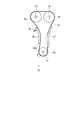
図1は、本発明の第1実施形態であるチェーン式動力伝達システムの構成を示す模式図である。
Hereinafter, embodiments of the present invention will be described with reference to the drawings.
FIG. 1 is a schematic diagram showing a configuration of a chain type power transmission system according to a first embodiment of the present invention.
本実施形態において、チェーン式動力伝達システム10は、クランクシャフト11からカムシャフト12へと動力を伝達する内燃機関のタイミングドライブシステムとして用いられる。タイミングチェーン(チェーン)13は、クランクシャフトスプロケット(原動スプロケット)14およびカムシャフトスプロケット(従動スプロケット)15に掛け回され、クランクシャフトスプロケット14とカムシャフトスプロケット15とを結ぶチェーンスパンはチェーンガイド(ガイド部材)16、17によって案内される。
In the present embodiment, the chain type
チェーンガイド16は、その一端が回転軸16Aを中心にエンジンブロックに枢着されるとともにバネや油圧等を用いた付勢部材18を用いて、回転軸16Aを中心に回転付勢される。すなわち、チェーンガイド16は、タイミングチェーン13を押圧してタイミングチェーン13の張力を調整するテンショナレバーとして機能する。また、チェーンガイド17は例えばエンジンブロックに固定されている。
One end of the
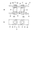
図2は、タイミングチェーン13の部分拡大図であり、図2(a)は平面図、図2(b)は側面図である。
2 is a partially enlarged view of the
タイミングチェーン13は、従来周知のように、一対の内側リンクプレート19と一対の外側リンクプレート20とを交互に連接して構成される。本実施形態では、内側リンクプレート19および外側リンクプレート20に、略同一形状のプレートが用いられる。各リンクプレート19、20は、例えば長方形の薄板部材の両端をそれぞれ略半円形に成形した形状を呈し、両端部には穴19A、20Aがそれぞれ設けられる。
As is conventionally known, the
一対の内側リンクプレート19の端部は、穴19Aが連接される一対の外側リンクプレート20の穴20Aと重なり合うように、外側リンクプレート20の端部の内側に配置され、重ね合わせられた穴19A、20Aには、それぞれピン21が挿通される。このように、内側リンクプレート19と外側リンクプレート20は、ピン21により回転可能に交互に連結される。また、本実施形態のタイミングチェーン13は、例えばローラチェーンであり、ピン21の周りには各々ローラ22が装着される。なお、ピン21とローラ22の間には通常ブッシュが介挿されるが本図では省略されている。
The end portions of the pair of
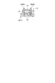
図3は、チェーンガイド16(または17)に接触するタイミングチェーン13と、チェーンガイド16(17)との関係を示す横断面図である。図3に示されるように、タイミングチェーン13は、リンクプレート19(または20)のチェーン長手方向に沿った端面23において、チェーンガイド16(17)の摺接面24に摺接し、チェーンガイド16(17)に沿って走行される。
FIG. 3 is a cross-sectional view showing the relationship between the
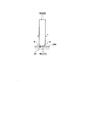
図4は、図3の左側のリンクプレート19(20)の断面形状を拡大して示したものである。従来リンクプレートの長手方向に沿った端面は、平坦面とされているので、リンクプレートは、チェーンガイドの摺接面と、リンクプレート厚さ方向に沿って、その厚さtに渡って接触する。一方、本実施形態では、リンクプレート19(20)の端面23の一方のエッジ部にアール(R)が設けられる。図3の例では、両側に配置されたリンクプレート19(20)の端面23の外側のエッジ部にアールが設けられている。
FIG. 4 is an enlarged view of the cross-sectional shape of the link plate 19 (20) on the left side of FIG. Since the end surface along the longitudinal direction of the conventional link plate is a flat surface, the link plate contacts the sliding contact surface of the chain guide over the thickness t along the link plate thickness direction. . On the other hand, in this embodiment, a radius (R) is provided at one edge portion of the
リンクプレート19、20の長手方向に沿った端面23の一方のエッジ部にアールを設けることにより、リンクプレート19、20とチェーンガイド16(17)との間の、プレート厚さ方向に沿った接触面積を、プレート厚さ全体に渡って接触する場合よりも小さくすることができる。
Contact is provided along the plate thickness direction between the
なお、本実施形態のように片側のエッジ部にのみにアールを設ける場合には、リンクプレートを型抜き加工により形成し、この型抜き加工においてアールを予め設けることも可能である。また、打ち抜き加工によりリンクプレートを形成した後に、エッジ部に対して研磨等の機械処理を施してアールを形成してもよい。 In addition, when providing a round only in the edge part of one side like this embodiment, it is also possible to form a link plate by a die cutting process and to provide a round in advance in this die cutting process. Further, after the link plate is formed by punching, the edge portion may be subjected to mechanical processing such as polishing to form a radius.
以上のように第1実施形態によれば、リンクプレートのチェーン長手方向に沿った他面のエッジ部にアール(湾曲部)を設けることにより、リンクプレート厚さ方向に沿ったリンクプレートの端面とチェーンガイドの摺接面との間の接触面積を小さくしている。これにより、リンクプレート端面とチェーンガイドの摺接面との間における潤滑液の膜形成を促進し、摩擦抵抗を小さくして摩擦損失を低減することができる。また、接触面積を小さくすることにより、面圧が高まり、リンクプレートは摺接面との接触により早期に平滑化され、摩擦係数が低減され得る。 As described above, according to the first embodiment, by providing a radius (curved portion) at the edge portion of the other surface along the chain longitudinal direction of the link plate, the end surface of the link plate along the link plate thickness direction The contact area between the sliding surface of the chain guide is reduced. Thereby, the film formation of the lubricating liquid between the link plate end surface and the sliding contact surface of the chain guide can be promoted, the frictional resistance can be reduced, and the friction loss can be reduced. Further, by reducing the contact area, the surface pressure increases, and the link plate can be smoothed at an early stage by contact with the sliding contact surface, and the friction coefficient can be reduced.
次ぎに図5に第1実施形態の変形例を示す。この変形例では、リンクプレート19、20の端面23の両エッジ部にアール(R)が設けられている。このように、他面23の両エッジ部にアール(R)を設けても、第1実施形態と同様の効果を得ることができる。
Next, FIG. 5 shows a modification of the first embodiment. In this modification, R (R) is provided at both edge portions of the
なお、第1実施形態では外側のエッジ部にアールを設ける構成としたが、内側のエッジ部にアールを設ける構成であってもよい。また、アールが設けられるエッジ部を一方のリンクプレートのみとすることも可能であり、または一方のリンクプレートは外側にアールを設け、他方を内側に設ける構成や、これらと変形例の構成を組み合わせることも可能である。 In addition, although it was set as the structure which provides a round at an outer edge part in 1st Embodiment, the structure which provides a round at an inner edge part may be sufficient. Further, it is possible to use only one link plate as an edge portion where a round is provided, or one link plate is provided with a round on the outside and the other is provided on the inside, or a combination of these and the configuration of the modified example. It is also possible.
次ぎに図6を参照して、本発明の第2実施形態について説明する。第2実施形態は、第1実施形態におけるリンクプレートの端面23の形状が異なるのみで、その他の構成に関しては第1実施形態と同様である。したがって、第1実施形態と異なる構成についてのみ図6を参照して説明する。
Next, a second embodiment of the present invention will be described with reference to FIG. The second embodiment is the same as the first embodiment with respect to the other configurations, except that the shape of the
図6は、第1実施形態およびその変形例における図4、図5に対応するリンクプレートの横断面図である。第2実施形態のリンクプレート(内側、外側を含む)25のチェーン長手方向に沿った端面26には、エッジ部にアールを設ける代わりに、長手方向に沿って少なくとも1つ以上の溝(湾曲部)27が形成され、図6の例では、3つの溝27が端面26に形成されている。
FIG. 6 is a cross-sectional view of the link plate corresponding to FIGS. 4 and 5 in the first embodiment and its modification. The
以上のように、第2実施形態においても、第1実施形態と同様にリンクプレート厚さ方向に沿った接触面積を、端面が平面であるときよりも小さくでき、第1実施形態と同様の効果を得ることができる。 As described above, also in the second embodiment, the contact area along the thickness direction of the link plate can be made smaller than in the case where the end face is a plane, as in the first embodiment, and the same effect as in the first embodiment. Can be obtained.
次ぎに図7を参照して、本発明の第3実施形態について説明する。第1および第2実施形態では、リンクプレートの端面に湾曲部を設けることにより、リンクプレートとチェーンガイドとの間のリンクプレート厚さ方向に沿った接触面積を低減していたが、第3実施形態では、チェーンガイドの摺接面に加工を施すことにより接触面積を低減している。 Next, a third embodiment of the present invention will be described with reference to FIG. In the first and second embodiments, the curved plate is provided on the end surface of the link plate to reduce the contact area along the link plate thickness direction between the link plate and the chain guide. In the embodiment, the contact area is reduced by processing the sliding contact surface of the chain guide.
図7は、図4〜図6に対応する図であり、リンクプレートとチェーンガイドのチェーン走行方向に対して垂直な面に沿った断面図である。第3実施形態において、リンクプレート28は、長手方向に沿った端面29が平坦面とされている。これに対して、チェーンガイド30の摺接面31には、チェーン走行方向に沿って複数の溝32が設けられる。溝32は、リンクプレート28の厚さtよりも狭い間隔で刻設される。すなわち、端面29は、少なくとも1つの溝32と常に対面し、端面29と摺接面31との間の接触面積は端面29と摺接面31が平面のときよりも低減される。
FIG. 7 is a view corresponding to FIGS. 4 to 6, and is a cross-sectional view of the link plate and the chain guide along a plane perpendicular to the chain traveling direction. In the third embodiment, the
以上のように、本発明の第3実施形態においても、第1、第2実施形態と同様の効果を得ることができる。 As described above, also in the third embodiment of the present invention, the same effects as those in the first and second embodiments can be obtained.
なお、本実施形態では、図1に示されるように、チェーンガイドがチェーンの外側端面とのみ摺接するので、第1実施形態、変形例、第2実施形態におけるチェーンの端面への加工は外側の端面にのみ施せばよいが、チェーンガイドが内側端面にも摺接される場合には、チェーン内側の端面にも同様の加工が施される。 In this embodiment, as shown in FIG. 1, since the chain guide is in sliding contact with only the outer end surface of the chain, the processing on the end surface of the chain in the first embodiment, the modified example, and the second embodiment is performed on the outer side. However, when the chain guide is also slidably contacted with the inner end surface, the same processing is performed on the inner end surface.
また、本実施形態ではリンクプレートの端面は、チェーン長手方向に沿った平行で直線的なものとされたが、リンクプレートには、従来周知のような中央部が括れた薄板部材を作用してもよい。また、本実施形態では、ローラチェーンを例に説明を行ったが、チェーンの形式は他の形式であってもよい。 In this embodiment, the end face of the link plate is parallel and linear along the longitudinal direction of the chain. However, a thin plate member with a central portion that is conventionally known acts on the link plate. Also good. In the present embodiment, the roller chain has been described as an example, but the chain may be of other types.
10 タイミングドライブシステム(チェーン式動力伝達システム)
13 タイミングチェーン
14 クランクシャフトスプロケット
15 カムシャフトスプロケット
16、17 チェーンガイド(ガイド部材)
19 内側リンクプレート
20 外側リンクプレート
23 端面
24、31 摺接面
27 溝
32 溝
10 Timing drive system (chain power transmission system)
13
19
Claims (8)
In a chain transmission system, a guide member that is in sliding contact with an end surface of a link plate of a chain and guides the travel of the chain, the end surface of the link plate along the thickness direction of the link plate and a sliding contact surface of the guide member The chain-type transmission is reduced by forming a plurality of grooves along the running direction of the chain at intervals narrower than the link plate thickness on the sliding contact surface. Guide member of the system.
Priority Applications (1)
| Application Number | Priority Date | Filing Date | Title |
|---|---|---|---|
| JP2008206138A JP5437607B2 (en) | 2008-08-08 | 2008-08-08 | Chain and chain-type power transmission system |
Applications Claiming Priority (1)
| Application Number | Priority Date | Filing Date | Title |
|---|---|---|---|
| JP2008206138A JP5437607B2 (en) | 2008-08-08 | 2008-08-08 | Chain and chain-type power transmission system |
Publications (2)
| Publication Number | Publication Date |
|---|---|
| JP2010043653A true JP2010043653A (en) | 2010-02-25 |
| JP5437607B2 JP5437607B2 (en) | 2014-03-12 |
Family
ID=42015200
Family Applications (1)
| Application Number | Title | Priority Date | Filing Date |
|---|---|---|---|
| JP2008206138A Active JP5437607B2 (en) | 2008-08-08 | 2008-08-08 | Chain and chain-type power transmission system |
Country Status (1)
| Country | Link |
|---|---|
| JP (1) | JP5437607B2 (en) |
Cited By (3)
| Publication number | Priority date | Publication date | Assignee | Title |
|---|---|---|---|---|
| GB2499507A (en) * | 2012-02-03 | 2013-08-21 | Tsubakimoto Chain Co | Chain having chain guide contacting links curved in the widthwise and longitudinal directions |
| DE102016109223A1 (en) * | 2016-05-19 | 2017-11-23 | Volkswagen Aktiengesellschaft | Chain for a timing drive of a reciprocating internal combustion engine and control drive a reciprocating internal combustion engine with such a chain |
| DE102012107488B4 (en) * | 2011-08-24 | 2020-11-26 | Tsubakimoto Chain Co. | Chain transmission with a roller chain that has tabs with a convex contour |
Citations (3)
| Publication number | Priority date | Publication date | Assignee | Title |
|---|---|---|---|---|
| JP2006329221A (en) * | 2005-05-23 | 2006-12-07 | Toyota Motor Corp | Chain type transmission device |
| JP2006342880A (en) * | 2005-06-08 | 2006-12-21 | Toyota Motor Corp | Chain type transmission device |
| JP2008025744A (en) * | 2006-07-21 | 2008-02-07 | Tsubakimoto Chain Co | Low friction chain |
-
2008
- 2008-08-08 JP JP2008206138A patent/JP5437607B2/en active Active
Patent Citations (3)
| Publication number | Priority date | Publication date | Assignee | Title |
|---|---|---|---|---|
| JP2006329221A (en) * | 2005-05-23 | 2006-12-07 | Toyota Motor Corp | Chain type transmission device |
| JP2006342880A (en) * | 2005-06-08 | 2006-12-21 | Toyota Motor Corp | Chain type transmission device |
| JP2008025744A (en) * | 2006-07-21 | 2008-02-07 | Tsubakimoto Chain Co | Low friction chain |
Cited By (7)
| Publication number | Priority date | Publication date | Assignee | Title |
|---|---|---|---|---|
| DE102012107488B4 (en) * | 2011-08-24 | 2020-11-26 | Tsubakimoto Chain Co. | Chain transmission with a roller chain that has tabs with a convex contour |
| GB2499507A (en) * | 2012-02-03 | 2013-08-21 | Tsubakimoto Chain Co | Chain having chain guide contacting links curved in the widthwise and longitudinal directions |
| US8968132B2 (en) | 2012-02-03 | 2015-03-03 | Tsubakimoto Chain Co. | Chain |
| GB2499507B (en) * | 2012-02-03 | 2018-02-07 | Tsubakimoto Chain Co | Chain |
| DE102013201462B4 (en) * | 2012-02-03 | 2020-03-26 | Tsubakimoto Chain Co. | Chain |
| DE102016109223A1 (en) * | 2016-05-19 | 2017-11-23 | Volkswagen Aktiengesellschaft | Chain for a timing drive of a reciprocating internal combustion engine and control drive a reciprocating internal combustion engine with such a chain |
| CN107420486A (en) * | 2016-05-19 | 2017-12-01 | 大众汽车有限公司 | For controlling the chain of transmission device and there is the control transmission device of this chain |
Also Published As
| Publication number | Publication date |
|---|---|
| JP5437607B2 (en) | 2014-03-12 |
Similar Documents
| Publication | Publication Date | Title |
|---|---|---|
| KR101436203B1 (en) | Power transmission chain | |
| US7419449B2 (en) | Low friction chain | |
| JP5253428B2 (en) | Link plate | |
| JP4368912B2 (en) | Engine transmission chain | |
| KR101698749B1 (en) | Guide plate and chain | |
| US11280385B2 (en) | Transfer belt | |
| JP2013044386A (en) | Chain transmission apparatus | |
| EP2100055B1 (en) | Silent chain | |
| US8968132B2 (en) | Chain | |
| JP2009103231A (en) | Transmission chain for engine | |
| JP2016532826A (en) | Low-mass chain link and friction reduction assembly | |
| JP5437607B2 (en) | Chain and chain-type power transmission system | |
| JP2006329221A (en) | Chain type transmission device | |
| KR101717450B1 (en) | Chain | |
| JP2007032815A (en) | Power transmitting chain and power transmission device | |
| JP2005321066A (en) | Power transmission chain and power transmission unit using the same | |
| JP5317889B2 (en) | chain | |
| JP5187768B2 (en) | chain | |
| JP4893561B2 (en) | Power transmission chain and power transmission device | |
| JP4821258B2 (en) | Power transmission chain and power transmission device | |
| JP2008185119A (en) | Power transmission device | |
| JP2007100737A (en) | Power transmission chain and power transmission device using the same | |
| JP2011069412A (en) | Power transmission chain and power transmission device | |
| JP4507077B2 (en) | Power transmission chain and power transmission device including the same | |
| JP2009222106A (en) | Power transmission chain and power transmission device |
Legal Events
| Date | Code | Title | Description |
|---|---|---|---|
| A621 | Written request for application examination |
Free format text: JAPANESE INTERMEDIATE CODE: A621 Effective date: 20110701 |
|
| A977 | Report on retrieval |
Free format text: JAPANESE INTERMEDIATE CODE: A971007 Effective date: 20120525 |
|
| A131 | Notification of reasons for refusal |
Free format text: JAPANESE INTERMEDIATE CODE: A131 Effective date: 20120605 |
|
| A521 | Written amendment |
Free format text: JAPANESE INTERMEDIATE CODE: A523 Effective date: 20120801 |
|
| A131 | Notification of reasons for refusal |
Free format text: JAPANESE INTERMEDIATE CODE: A131 Effective date: 20130305 |
|
| A521 | Written amendment |
Free format text: JAPANESE INTERMEDIATE CODE: A523 Effective date: 20130501 |
|
| TRDD | Decision of grant or rejection written | ||
| A01 | Written decision to grant a patent or to grant a registration (utility model) |
Free format text: JAPANESE INTERMEDIATE CODE: A01 Effective date: 20131203 |
|
| A61 | First payment of annual fees (during grant procedure) |
Free format text: JAPANESE INTERMEDIATE CODE: A61 Effective date: 20131212 |
|
| R150 | Certificate of patent or registration of utility model |
Ref document number: 5437607 Country of ref document: JP Free format text: JAPANESE INTERMEDIATE CODE: R150 Free format text: JAPANESE INTERMEDIATE CODE: R150 |