JP2010042903A - Paper conveying device and image forming apparatus - Google Patents
Paper conveying device and image forming apparatus Download PDFInfo
- Publication number
- JP2010042903A JP2010042903A JP2008207989A JP2008207989A JP2010042903A JP 2010042903 A JP2010042903 A JP 2010042903A JP 2008207989 A JP2008207989 A JP 2008207989A JP 2008207989 A JP2008207989 A JP 2008207989A JP 2010042903 A JP2010042903 A JP 2010042903A
- Authority
- JP
- Japan
- Prior art keywords
- paper
- roller
- sheet
- correction control
- pair
- Prior art date
- Legal status (The legal status is an assumption and is not a legal conclusion. Google has not performed a legal analysis and makes no representation as to the accuracy of the status listed.)
- Granted
Links
Images


Landscapes
- Delivering By Means Of Belts And Rollers (AREA)
- Registering Or Overturning Sheets (AREA)
Abstract
Description
本発明は、用紙を搬送する用紙搬送装置及び用紙搬送装置を備えた画像形成装置に関し、特に、搬送される用紙の曲がりを補正する際に生じる用紙のシワを除去できるようにしたものである。 The present invention relates to a sheet conveying apparatus that conveys a sheet and an image forming apparatus including the sheet conveying apparatus. In particular, the present invention can remove wrinkles of a sheet that occur when correcting the bending of the conveyed sheet.
従来から、複写機等の画像形成装置では、搬送される用紙の曲がり(斜行)を補正する機能を有した用紙搬送装置が組み込まれている。従来の用紙搬送装置は、用紙の搬送方向に対して左右に並列されるレジストローラと称されるローラ対を備え、左右のローラ対による用紙の搬送速度(搬送量)を変化させることで、用紙の曲がりを補正している。 2. Description of the Related Art Conventionally, image forming apparatuses such as copiers have incorporated a paper transport device having a function of correcting the skew (skew) of the transported paper. A conventional paper transport device includes a pair of rollers called registration rollers arranged in parallel on the left and right with respect to the paper transport direction, and changes the paper transport speed (transport amount) by the left and right roller pairs. The bend is corrected.
このような従来の用紙搬送装置としては、用紙の搬送方向に対してローラ対の手前に配置される搬送ローラ対を、用紙から離間させる機構を備え、搬送される用紙が長い場合に搬送ローラ対を用紙から離間させ、用紙の長さ方向に生じるシワを防ぐ技術が提案されている(例えば、特許文献1参照)。 Such a conventional paper transport device includes a mechanism for separating the transport roller pair disposed in front of the roller pair in the paper transport direction from the paper, and the transport roller pair when the transported paper is long. A technique has been proposed in which wrinkles are separated from the paper and wrinkles that occur in the length direction of the paper are prevented (see, for example, Patent Document 1).
しかし、従来の用紙搬送装置は、左右のローラ対による用紙の搬送速度を変化させて用紙の曲がりを補正するので、用紙の幅方向にシワが発生するという問題があった。 However, the conventional sheet conveying apparatus has a problem that wrinkles occur in the width direction of the sheet because the sheet conveying speed by the pair of left and right rollers is changed to correct the bending of the sheet.
本発明は、このような課題を解決するためになされたもので、用紙の曲がりを補正することで発生するしわを除去できるようにした用紙搬送装置及びこの用紙搬送装置を備えた画像形成装置を提供することを目的とする。 SUMMARY An advantage of some aspects of the invention is to provide a sheet conveying apparatus capable of removing wrinkles generated by correcting the bending of the sheet and an image forming apparatus including the sheet conveying apparatus. The purpose is to provide.
上述した課題を解決するため、本発明は、用紙の搬送方向に対して左右に並列され、同軸上に配置される少なくとも2個の駆動ローラ及び駆動ローラとそれぞれ対向する従動ローラを有した給紙ローラ対と、駆動ローラを独立して駆動する給紙モータと、駆動ローラまたは従動ローラを、用紙に対して離接する方向に移動させ、少なくとも一方の給紙ローラ対を、用紙に対して離間及び圧着させる圧着離間機構と、用紙が曲がっているか否かを検知する検知センサと、給紙モータを制御して駆動ローラで用紙を搬送し、用紙の搬送方向に対する左右で搬送量を異ならせて、検知センサで検知された用紙の曲がりを補正する曲がり補正制御と、圧着離間機構を制御して一方の給紙ローラ対を用紙から離間させ、曲がり補正制御で発生した用紙のシワを、用紙の復元力で元に戻すシワ補正制御を行う制御部とを備えた用紙搬送装置である。 In order to solve the above-described problem, the present invention provides a sheet feeding device having at least two driving rollers arranged in parallel on the left and right sides with respect to the sheet conveyance direction and a driven roller facing each of the driving rollers. The pair of rollers, the paper feed motor that independently drives the drive roller, and the drive roller or the driven roller are moved in a direction to be separated from and contacted with the paper, and at least one paper feed roller pair is A pressure separation mechanism that performs pressure bonding, a detection sensor that detects whether or not the paper is bent, a paper feed motor that controls the paper to be transported by the drive roller, and the transport amount is different on the left and right with respect to the paper transport direction. Bending correction control that corrects the bending of the paper detected by the detection sensor, and one of the paper feed roller pairs is separated from the paper by controlling the pressure-separation separation mechanism. The word, a sheet conveying apparatus and a control unit for performing wrinkle correction control undo by the restoring force of the paper.
また、本発明は、用紙に画像を形成する画像形成部と、画像形成部に用紙を搬送する用紙搬送装置を備え、用紙搬送装置は、用紙の搬送方向に対して左右に並列され、同軸上に配置される少なくとも2個の駆動ローラ及び駆動ローラとそれぞれ対向する従動ローラを有した給紙ローラ対と、駆動ローラを独立して駆動する給紙モータと、駆動ローラまたは従動ローラを、用紙に対して離接する方向に移動させ、少なくとも一方の給紙ローラ対を、用紙に対して離間及び圧着させる圧着離間機構と、用紙が曲がっているか否かを検知する検知センサと、給紙モータを制御して駆動ローラで用紙を搬送し、用紙の搬送方向に対する左右で搬送量を異ならせて、検知センサで検知された用紙の曲がりを補正する曲がり補正制御と、圧着離間機構を制御して一方の給紙ローラ対を用紙から離間させ、曲がり補正制御で発生した用紙のシワを、用紙の復元力で元に戻すシワ補正制御を行う制御部とを備えた画像形成装置である。 In addition, the present invention includes an image forming unit that forms an image on a sheet, and a sheet conveying device that conveys the sheet to the image forming unit. A sheet feeding roller pair having at least two driving rollers and a driven roller respectively opposed to the driving roller, a sheet feeding motor for independently driving the driving roller, and a driving roller or a driven roller on the sheet. Controls the pressure separation mechanism that moves and separates the at least one paper feed roller pair from and against the paper, the detection sensor that detects whether the paper is bent, and the paper feed motor. Then, the sheet is conveyed by the drive roller, and the amount of conveyance is varied between the right and left with respect to the sheet conveyance direction, and the bending correction control for correcting the bending of the sheet detected by the detection sensor and the pressure separation mechanism are controlled. And by separating the one of the pair of feeding rollers from the sheet, wrinkles of the sheet generated by the correction control bending, an image forming apparatus and a control unit for performing wrinkle correction control undo by the restoring force of the paper.
本発明の用紙搬送装置及び画像形成装置では、検知センサで用紙の曲がり(斜行)が検知されると、検知センサで検知された用紙の曲がり量に基づき給紙モータを制御して、駆動ローラを独立して駆動し、用紙の搬送方向に対する左右で搬送量を異ならせて、用紙の曲がりを補正する曲がり補正制御が行われる。用紙の曲がり補正制御を行った後、圧着離間機構を制御して一方の給紙ローラ対を用紙から離間させ、曲がり補正制御で発生した用紙のシワを、用紙の復元力で元に戻すシワ補正制御が行われる。 In the paper conveying device and the image forming apparatus according to the present invention, when the detection sensor detects the bending (skew) of the paper, the paper feeding motor is controlled based on the paper bending amount detected by the detection sensor, and the driving roller Are independently driven, and the bending correction control for correcting the bending of the sheet is performed by changing the conveyance amount on the right and left with respect to the conveyance direction of the sheet. After the paper bending correction control is performed, the crimping and separation mechanism is controlled to separate one paper feed roller pair from the paper, and the paper wrinkles generated by the bending correction control are restored to the original with the paper restoring force. Control is performed.
本発明によれば、用紙の搬送方向に対して左右に並列される給紙ローラ対で、用紙の搬送量を異ならせて用紙の曲がり補正を行う場合に、左右の給紙ローラ対の間で用紙に発生するシワを除去することができる。 According to the present invention, when paper skew correction is performed by changing the amount of paper transport between the pair of paper feed rollers arranged side by side with respect to the paper transport direction, Wrinkles generated on the paper can be removed.
そして、左右の一方の給紙ローラ対による用紙の圧着を解除することで、用紙の復元力を利用してシワを除去するので、簡単な構成で確実に用紙のシワを除去することができる。 Then, by releasing the pressure-bonding of the paper by the pair of left and right paper feed rollers, the wrinkle is removed by utilizing the restoring force of the paper, so that the paper can be reliably removed with a simple configuration.
以下、図面を参照して本発明の用紙搬送装置及び画像形成装置の実施の形態について説明する。 Hereinafter, embodiments of a sheet conveying device and an image forming apparatus according to the present invention will be described with reference to the drawings.
<第1の実施の形態の用紙搬送装置の構成例>
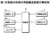
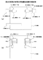
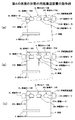
図1及び図2は、第1の実施の形態の用紙搬送装置の一例を示す構成図で、図1(a)は、第1の実施の形態の用紙搬送装置を駆動ローラの側から見た模式的な平面図、図1(b)は、第1の実施の形態の用紙搬送装置を従動ローラの側から見た模式的な平面図である。また、図2(a),図2(b)は、第1の実施の形態の用紙搬送装置を用紙の搬送方向に対する一の側方から見た模式的な側面図である。また、図3は、第1の実施の形態の用紙搬送装置の制御系の一例を示す機能ブロック図である。
<Configuration Example of Paper Conveying Device of First Embodiment>
FIGS. 1 and 2 are configuration diagrams showing an example of the sheet conveying apparatus according to the first embodiment. FIG. 1A is a diagram of the sheet conveying apparatus according to the first embodiment as viewed from the drive roller side. FIG. 1B is a schematic plan view of the sheet conveying apparatus according to the first embodiment viewed from the driven roller side. FIGS. 2A and 2B are schematic side views of the sheet conveying apparatus according to the first embodiment as viewed from one side with respect to the sheet conveying direction. FIG. 3 is a functional block diagram illustrating an example of a control system of the sheet conveying apparatus according to the first embodiment.
第1の実施の形態の用紙搬送装置1Aは、用紙Pを搬送する給紙ローラ対2L,2Rと、給紙ローラ対2L,2Rを独立して駆動する給紙モータ3L,3Rを備える。
The sheet conveying apparatus 1A according to the first embodiment includes sheet
給紙ローラ対2Lは、用紙Pの搬送方向に対して左側に配置され、給紙モータ3Lに駆動される駆動ローラ20Lと、駆動ローラ20Lに対向配置される従動ローラ21Lを備える。給紙ローラ対2Rは、用紙Pの搬送方向に対して右側に配置され、給紙モータ3Rに駆動される駆動ローラ20Rと、駆動ローラ20Rに対向配置される従動ローラ21Rを備える。
The paper
駆動ローラ20Lと駆動ローラ20Rは、独立した軸に支持されて同軸上に配置され、従動ローラ21Lと従動ローラ21Rは、独立した軸に支持されて同軸上に配置される。
The driving roller 20L and the driving roller 20R are supported on independent shafts and arranged coaxially, and the driven
駆動ローラ20Lは給紙モータ3Lの駆動力が伝達され、駆動ローラ20Rは給紙モータ3Rの駆動力が伝達されて、駆動ローラ20Lと駆動ローラ20Rは、独立して駆動が可能である。
The driving force of the
用紙搬送装置1Aは、給紙ローラ対2Lと給紙ローラ対2Rの何れか、本例では、給紙ローラ対2Rによる用紙Pの圧着及び圧着の解除を行う圧着離間機構4Rを備える。圧着離間機構4Rは、給紙ローラ対2Rを構成する駆動ローラ20Rと従動ローラ21Rのいずれか、本例では、従動ローラ21Rを用紙Pに対して圧着及び離間する方向に移動可能に支持する支持部材40Rを備える。また、圧着離間機構4Rは、従動ローラ21Rを用紙Pに対して圧着及び離間する方向に移動させるソレノイド及びバネ等を有した駆動部41Rを備える。
The sheet conveying apparatus 1A includes a pressure-separating / separating mechanism 4R for pressing and releasing the pressure-bonding of the paper P by the paper-feed roller pair 2R, in this example, the paper-
用紙搬送装置1Aは、用紙Pの曲がり量等を検知する検知センサ5を備える。検知センサ5は例えばラインセンサで構成され、用紙Pの幅方向における所定の範囲で用紙Pの搬送方向の先端位置が検知される。また。用紙Pの幅方向における一方の側端、本例では搬送方向に対して左端位置が検知される。
The sheet conveying apparatus 1A includes a
これにより、検知センサ5の出力から、搬送される用紙Pが曲がっているか否か、及び用紙Pの側端位置等が検知される。また、用紙Pが曲がっている場合は、検知センサ5の出力から、用紙Pの曲がり量と曲がり方向が検知される。例えば、用紙Pの幅方向において左右のどちらが先行(遅延)しているか、及び左右の先行(遅延)量が検知される。
Thereby, from the output of the
用紙搬送装置1Aは、検知センサ5の出力に基づいて、用紙Pの搬送制御を行う制御部6を備える。制御部6は、検知センサ5の出力から検知された用紙Pの曲がり量と曲がり方向に基づき給紙モータ3L及び給紙モータ3Rを制御して、用紙Pの曲がりを補正する曲がり補正制御を行う。また、圧着離間機構4Rを制御して、曲がり補正制御によって用紙Pに発生したシワを除去するシワ補正制御を行う。
The
用紙搬送装置1Aは、搬送される用紙Pの紙情報が設定される情報設定部7を備える。情報設定部7は、用紙Pのサイズ、紙種、坪量、紙目等の紙情報が操作者等によって予め設定され、設定された紙情報が図示しない記憶部に記憶される。
The sheet conveying apparatus 1A includes an
制御部6は、シワ補正制御で用紙Pから離間させる従動ローラ21Rによる用紙Pの再圧着の有無を示す再圧着フラグNと、再圧着を行う場合の離間時間であるシワ補正時間Tを、情報設定部7で設定された紙情報に基づいて設定する。
The
<画像形成装置の構成例>
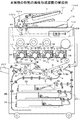
図4は、本発明の用紙搬送装置が適用された本実施の形態の画像形成装置の一例を示す全体構成図である。本実施の形態の画像形成装置100Aは、画像形成装置本体GHと画像読取装置YS等を備える。画像形成装置本体GHは、タンデム型カラー画像形成部と称されるもので、複数組の画像形成ユニット10Y,10M,10C,10Kと、中間転写体16と、2次転写部17A等を備える。
<Configuration example of image forming apparatus>
FIG. 4 is an overall configuration diagram illustrating an example of the image forming apparatus according to the present embodiment to which the sheet conveying device of the present invention is applied. The
画像形成装置本体GHの上部には、自動原稿送り装置101と走査露光装置102を備えた画像読取装置YSが設置されている。自動原稿送り装置101の原稿台上に載置された原稿dは、搬送部101aにより搬送され、走査露光装置102の光学系102aにより原稿dの片面または両面の画像が走査露光され、ラインイメージセンサCCDに読み込まれる。
An image reading device YS including an
ラインイメージセンサCCDにより光電変換された画像信号は、図示しない画像処理部において、アナログ処理、A/D変換、シェーディング補正、画像圧縮処理等が行われた後、露光部13Y,13M,13C,13Kに送られる。
The image signal photoelectrically converted by the line image sensor CCD is subjected to analog processing, A / D conversion, shading correction, image compression processing, etc. in an image processing unit (not shown), and then exposed to the
イエロー(Y)色の画像を形成する画像形成ユニット10Yは、ドラム状の感光体11Yの周囲に帯電部12Y、露光部13Y、現像部14Y、一次転写部17Y及びクリーニング部18Yを有する。マゼンタ(M)色の画像を形成する画像形成ユニット10Mは、ドラム状の感光体11Mの周囲に帯電部12M、露光部13M、現像部14M、一次転写部17M及びクリーニング部18Mを有する。
The
シアン(C)色の画像を形成する画像形成ユニット10Cは、ドラム状の感光体11Cの周囲に帯電部12C、露光部13C、現像部14C、一次転写部17C及びクリーニング部18Cを有する。黒(Bk)色の画像を形成する画像形成ユニット10Kは、ドラム状の感光体11Kの周囲に帯電部12K、露光部13K、現像部14K、一次転写部17K及びクリーニング部18Kを有する。そして、帯電部12Yと露光部13Y、帯電部12Mと露光部13M、帯電部12Cと露光部13C、及び帯電部12Kと露光部13Kは、潜像形成部を構成する。
An image forming unit 10C for forming a cyan (C) color image includes a charging unit 12C, an exposure unit 13C, a developing unit 14C, a primary transfer unit 17C, and a cleaning unit 18C around a drum-shaped photoconductor 11C. The
なお、現像部14Y,14M,14C,14Kは、イエロー(Y)、マゼンタ(M)、シアン(C)及び黒(K)のトナーとキャリアからなる2成分現像剤を収容している。
The developing
中間転写体16は、複数のローラにより巻回され、回動可能に支持されている。定着装置19は、定着ローラ93及び加圧ローラ94を有し、定着ローラ93と加圧ローラ94との間に形成されたニップ部で用紙P上のトナー像を加熱及び加圧して定着する。 The intermediate transfer member 16 is wound around a plurality of rollers and is rotatably supported. The fixing device 19 includes a fixing roller 93 and a pressure roller 94, and fixes the toner image on the paper P by heating and pressing at a nip portion formed between the fixing roller 93 and the pressure roller 94.
画像形成ユニット10Y,10M,10C,10Kより形成された各色のトナー像は、回動する中間転写体16上に一次転写部17Y,17M,17C,17Kにより逐次転写され、中間転写体16上に各色のトナー像が重ね合わされたカラートナー像が形成される。
The toner images of the respective colors formed by the
給紙トレイ200内に収容された用紙Pは、給紙部201の分離繰出ローラ202により1枚毎に分離され、給紙ローラ203で用紙搬送装置1Aに搬送される。画像形成装置100Aにおいて、図1及び図2で説明した給紙ローラ対2L,2Rはレジストローラと称される。
The paper P stored in the
給紙ローラ203で給紙ローラ対2L,2Rへ給紙された用紙Pは、必要に応じて後述する曲がり補正制御及びシワ補正制御を行った後、給紙ローラ対2L,2Rで一旦停止される。そして、用紙Pの先端と中間転写体16上のトナー像との位置が一致するタイミングで、給紙ローラ対2L,2Rが回転を開始することにより、用紙Pが2次転写部17Aに給紙され、用紙P上にカラートナー像が転写される(2次転写)。
The paper P fed to the paper
カラートナー像が転写された用紙Pは、定着装置19において加熱及び加圧され、用紙P上にカラートナー像が定着される。カラートナー像が定着された用紙Pは、排紙ローラ204に搬送されて機外の排紙トレイ205上に排紙される。
The paper P on which the color toner image has been transferred is heated and pressurized by the fixing device 19, and the color toner image is fixed on the paper P. The paper P on which the color toner image has been fixed is conveyed to a
一方、2次転写部17Aにより用紙Pにカラートナー像を転写した後、用紙Pを曲率分離した中間転写体16は、中間転写体クリーニング部18Aにより残留トナーが除去される。 On the other hand, after the color toner image is transferred to the paper P by the secondary transfer unit 17A, the residual toner is removed by the intermediate transfer member cleaning unit 18A from the intermediate transfer member 16 that has separated the curvature of the paper P.
なお、以上はカラー画像を形成する画像形成装置であったが、モノクロ画像を形成する画像形成装置であっても良い。 Although the above is an image forming apparatus that forms a color image, an image forming apparatus that forms a monochrome image may be used.
<第1の実施の形態の用紙搬送装置の動作例>
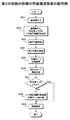
図5は、第1の実施の形態の用紙搬送装置の動作の一例を示すフローチャート、図6は、第1の実施の形態の用紙搬送装置における曲がり補正制御及びシワ補正制御の一例を示す動作説明図で、次に、各図を参照して第1の実施の形態の用紙搬送装置1A及び画像形成装置100Aの動作例について説明する。なお、図6において、用紙Pに対して従動ローラが圧着されている給紙ローラ対は実線で示し、従動ローラが離間して圧着が解除されている給紙ローラ対は模式的に破線で示している。
<Example of Operation of Paper Conveying Device of First Embodiment>
FIG. 5 is a flowchart showing an example of the operation of the sheet conveying apparatus of the first embodiment, and FIG. 6 is an explanation of the operation showing an example of the bending correction control and the wrinkle correction control in the sheet conveying apparatus of the first embodiment. Next, operation examples of the sheet conveying apparatus 1A and the
用紙搬送装置1Aは、上述したように画像形成装置100Aに組み込まれ、画像形成処理に先立って、制御部6は、ステップSA1の処理で、情報設定部7から紙情報を入手する。そして、制御部6は、ステップSA2の処理で、シワ補正制御後の従動ローラ21Rによる用紙Pの再圧着の有無を示す再圧着フラグNと、再圧着を行う場合のシワ補正時間Tを設定する。
As described above, the sheet conveying apparatus 1A is incorporated in the
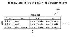
図7は、紙情報と再圧着フラグ及びシワ補正時間の関係の一例を示すテーブルの説明図である。テーブル300は、紙情報として設定される紙種と紙サイズに対応して、再圧着フラグNとシワ補正時間Tが設定される。図7では、再圧着フラグN=0は再圧着無、再圧着フラグN=1は再圧着有の設定である。また、再圧着フラグN=1の場合は、シワ補正時間Tが設定されている。制御部6は、情報設定部7から入手した紙情報に基づき、テーブル300を参照して再圧着フラグNとシワ補正時間Tを設定する。
FIG. 7 is an explanatory diagram of a table showing an example of the relationship between the paper information, the recompression flag, and the wrinkle correction time. In the table 300, a recompression flag N and a wrinkle correction time T are set in accordance with the paper type and paper size set as the paper information. In FIG. 7, the re-compression flag N = 0 is set so that there is no re-compression, and the re-compression flag N = 1 is set to have re-compression. When the re-compression flag N = 1, the wrinkle correction time T is set. The
用紙搬送装置1Aは、画像形成装置100Aの給紙トレイ200内に収容された用紙Pが、給紙部201の分離繰出ローラ202により1枚毎に分離され、給紙ローラ203によって検知センサ5に給紙される。
In the sheet conveying apparatus 1A, the sheets P stored in the
制御部6は、ステップSA3の処理で、搬送される用紙Pが曲がっているか否かを検知センサ5の出力から検知し、用紙Pが曲がっている場合は、用紙Pの曲がり量を検知する。
In step SA3, the
制御部6は、検知センサ5の出力から図6(a)に実線で示すように用紙Pが曲がっていると検知すると、ステップSA4の処理で、用紙Pの曲がりを補正する補正制御を行う。用紙Pの曲がり補正制御では、制御部6は、検知センサ5で検知された用紙Pの曲がり量に基づいて、用紙Pの曲がりを補正するために必要な給紙モータ3L及び給紙モータ3Rの駆動時間及び回転数等を設定する。
When the
制御部6は、用紙Pの曲がり量に基づき設定された駆動時間及び回転数で給紙モータ3Lと給紙モータ3Rを制御して、駆動ローラ20Lと駆動ローラ20Rの回転速度に差を付けて駆動する。これにより、用紙Pにおいて駆動ローラ20Lによって搬送される搬送方向に対する左側と、駆動ローラ20Rによって搬送される右側で搬送量を異ならせて、図6(b)に二点鎖線で示す状態から、図6(b)に実線で示すように、用紙Pにおいて先行している側と遅延している側の先端位置を揃える。
The
制御部6は、検知センサ5で検知された用紙Pの曲がり量に基づいて給紙モータ3Lと給紙モータ3Rを制御して、用紙Pの曲がりを補正すると、給紙モータ3Lと給紙モータ3Rを制御して、駆動ローラ20Lと駆動ローラ20Rの駆動を停止する。
When the
用紙Pの曲がり補正制御では、用紙Pの幅方向において左右の両側に配置される駆動ローラ20Lと駆動ローラ20Rによる搬送量に差を付けて用紙Pを搬送することで、図6(b)に示すように、用紙Pは幅方向にシワPeが生じる。そこで、ステップSA5の処理で、用紙Pのシワを補正する補正制御を行う。 In the bending correction control of the paper P, the paper P is transported with a difference in the transport amount by the driving roller 20L and the driving roller 20R arranged on both the left and right sides in the width direction of the paper P, thereby FIG. As shown, the paper P has wrinkles Pe in the width direction. Therefore, correction control for correcting wrinkles of the paper P is performed in the process of step SA5.
用紙Pのシワ補正制御では、制御部6は、圧着離間機構4Rを制御して、図2(b)に示すように従動ローラ21Rを用紙Pから離間させる。これにより、用紙Pは、給紙ローラ対2L側では、駆動ローラ20Lと従動ローラ21Lとの間に挟持されて圧着された状態が保持されると共に、給紙ローラ対2R側では、駆動ローラ20Rと従動ローラ21Rによる圧着が解除される。
In the wrinkle correction control of the paper P, the
曲がり補正制御で用紙Pに生じたシワPeは、従動ローラ21Rを用紙Pから離間させて、駆動ローラ20Rと従動ローラ21Rによる用紙Pの挟持を解除することで、用紙Pのコシによる復元力で伸ばされ、図6(c)に示すように、用紙Pはシワの無い平らな状態に戻される。 The wrinkle Pe generated on the paper P by the bending correction control causes the driven roller 21R to be separated from the paper P, and the pinching of the paper P by the driving roller 20R and the driven roller 21R is released. As shown in FIG. 6C, the sheet P is returned to a flat state without wrinkles.
制御部6は、ステップSA6の処理で、再圧着フラグNが従動ローラ21Rによる再圧着有と設定されているか、再圧着無と設定されているかを判断する。
In step SA6, the
制御部6は、再圧着フラグNが従動ローラ21Rによる再圧着有と設定されていると、ステップSA7の処理で、紙情報に基づいて予め設定したシワ補正時間Tが経過した後、圧着離間機構4Rを制御して、従動ローラ21Rで用紙Pを駆動ローラ20Rに圧着する。
When the re-compression flag N is set to be re-compressed by the driven roller 21R, the
そして、制御部6は、ステップSA8の処理で、給紙ローラ対2Lと給紙ローラ対2Rの双方で駆動ローラ20L,20Rと従動ローラ21L,21Rにより用紙Pを挟持した状態で給紙モータ3Lと給紙モータ3Rを制御して、駆動ローラ20Lと駆動ローラ20Rを同速度で駆動し、用紙Pを搬送する。
In step SA8, the
制御部6は、再圧着フラグNが従動ローラ21Rによる再圧着無と設定されていると、給紙ローラ対2Rによる圧着は解除した状態を保ち、ステップSA8の処理で、給紙ローラ対2Lで駆動ローラ20Lと従動ローラ21Lにより用紙Pを挟持した状態で給紙モータ3Lを制御して駆動ローラ20Lを駆動し、用紙Pを搬送する。
When the re-compression flag N is set so that the re-compression by the driven roller 21R is not performed, the
一般的に、用紙のサイズが小さい場合は、片側の給紙ローラ対だけで用紙を搬送しても、用紙の曲がりは発生し難い。一方、用紙のサイズが大きい場合は、片側の給紙ローラ対だけで用紙を搬送すると、用紙の曲がりが発生する可能性があり、両側の給紙ローラ対で用紙を搬送する必要がある。そこで、情報設定部7で設定される紙情報として、図7に示すように、用紙のサイズを設定できるようにして、例えば、用紙の大きさがA4であれば、再圧着フラグNで再圧着無と設定され、用紙の大きさがA3以上であれば、再圧着フラグNで再圧着有と設定される。また、用紙の表面が滑りやすいと、片側の給紙ローラ対だけで用紙を搬送すると、用紙の曲がりが発生する可能性があり、両側の給紙ローラ対で用紙を搬送する必要がある。そこで、情報設定部7で設定される紙情報として、図7に示すように、用紙の紙種を設定できるようにして、例えば、紙種がコート紙であれば、用紙の大きさがA4であっても、再圧着フラグNで再圧着有と設定される。
In general, when the paper size is small, even if the paper is transported by only one pair of paper feed rollers, the paper is unlikely to be bent. On the other hand, if the paper size is large, the paper may be bent when the paper is transported only by the pair of paper feed rollers on one side, and the paper must be transported by the pair of paper feed rollers on both sides. Therefore, as the paper information set by the
このように、シワ補正制御で用紙から離間させた従動ローラについて、用紙のサイズ及び紙種に応じて再圧着の有無が設定されることで、曲がり補正制御及びシワ補正制御で曲がり及びシワが補正された用紙が、再度曲がって搬送されることを防ぐことができる。また、再圧着が不要な用紙では再圧着の動作を省略することで、処理時間を短縮することができる。なお、シワ補正制御後の従動ローラの再圧着の有無の設定は、図7に示すようなテーブルでも良いし、補正量を決めておいてこれを利用しても良い。また、シワ補正制御後の従動ローラの再圧着の有無を、紙種等によらずどちらか一方に固定しても良い。 In this way, for the driven roller separated from the paper by the wrinkle correction control, the presence / absence of re-compression is set according to the paper size and paper type, so that the bend and wrinkle are corrected by the bending correction control and the wrinkle correction control. It is possible to prevent the used paper from being bent and conveyed again. Further, the processing time can be shortened by omitting the re-compression operation for the paper that does not require re-compression. In addition, the setting as to whether or not the re-pressing of the driven roller after the wrinkle correction control may be set using a table as shown in FIG. 7, or a correction amount may be determined and used. Further, the presence / absence of re-pressurization of the driven roller after the wrinkle correction control may be fixed to either one regardless of the paper type or the like.
図4で説明した画像形成装置100Aでは、中間転写体16上のトナー像との位置が一致するタイミングで、再圧着フラグNに基づいて駆動ローラ20Lまたは駆動ローラ20L,20Rが回転を開始することにより、用紙Pが2次転写部17Aに給紙される。
In the
<第2の実施の形態の用紙搬送装置の構成例>
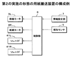
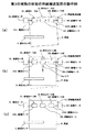
図8及び図9は、第2の実施の形態の用紙搬送装置の一例を示す構成図で、図8(a)は、第2の実施の形態の用紙搬送装置を駆動ローラの側から見た模式的な平面図、図8(b)は、第2の実施の形態の用紙搬送装置を従動ローラの側から見た模式的な平面図である。また、図9(a),図9(b)は、第2の実施の形態の用紙搬送装置を用紙の搬送方向に対する一の側方から見た模式的な側面図である。また、図10は、第2の実施の形態の用紙搬送装置の制御系の一例を示す機能ブロック図である。
<Example of Configuration of Paper Conveying Device of Second Embodiment>
FIGS. 8 and 9 are configuration diagrams showing an example of the sheet conveying apparatus according to the second embodiment. FIG. 8A shows the sheet conveying apparatus according to the second embodiment as viewed from the drive roller side. FIG. 8B is a schematic plan view of the sheet conveying apparatus according to the second embodiment viewed from the driven roller side. FIGS. 9A and 9B are schematic side views of the sheet conveying apparatus according to the second embodiment as viewed from one side with respect to the sheet conveying direction. FIG. 10 is a functional block diagram illustrating an example of a control system of the sheet conveying apparatus according to the second embodiment.
第2の実施の形態の用紙搬送装置1Bは、用紙Pを搬送する給紙ローラ対2L,2Rと、給紙ローラ対2L,2Rを独立して駆動する給紙モータ3L,3Rを備える。
The sheet conveying apparatus 1B according to the second embodiment includes sheet feeding
給紙ローラ対2Lは、用紙Pの搬送方向に対して左側に配置され、給紙モータ3Lに駆動される駆動ローラ20Lと、駆動ローラ20Lに対向配置される従動ローラ21Lを備える。給紙ローラ対2Rは、用紙Pの搬送方向に対して右側に配置され、給紙モータ3Rに駆動される駆動ローラ20Rと、駆動ローラ20Rに対向配置される従動ローラ21Rを備える。
The paper
駆動ローラ20Lと駆動ローラ20Rは、独立した軸に支持されて同軸上に配置され、従動ローラ21Lと従動ローラ21Rは、独立した軸に支持されて同軸上に配置される。
The driving roller 20L and the driving roller 20R are supported on independent shafts and arranged coaxially, and the driven
駆動ローラ20Lは給紙モータ3Lの駆動力が伝達され、駆動ローラ20Rは給紙モータ3Rの駆動力が伝達されて、駆動ローラ20Lと駆動ローラ20Rは、独立して駆動が可能である。
The driving force of the
用紙搬送装置1Bは、給紙ローラ対2L,2Rによる用紙Pの圧着及び圧着の解除を行う圧着離間機構4L,4Rを備える。圧着離間機構4Lは、給紙ローラ対2Lを構成する駆動ローラ20Lと従動ローラ21Lの何れか、本例では従動ローラ21Lを、用紙Pに対して圧着及び離間する方向に移動可能に支持する支持部材40Lを備える。また、圧着離間機構4Lは、従動ローラ21Lを用紙Pに対して圧着及び離間する方向に移動させるソレノイド及びバネ等を有した駆動部41Lを備える。
The sheet transport apparatus 1B includes pressure-bonding / separating mechanisms 4L and 4R that perform pressure-bonding and release of the pressure-bonding of the paper P by the pair of
圧着離間機構4Rは、給紙ローラ対2Rを構成する駆動ローラ20Rと従動ローラ21Rのいずれか、本例では従動ローラ21Rを、用紙Pに対して圧着及び離間する方向に移動可能に支持する支持部材40Rを備える。また、圧着離間機構4Rは、従動ローラ21Rを用紙Pに対して圧着及び離間する方向に移動させるソレノイド及びバネ等を有した駆動部41Rを備える。
The pressure separation / separation mechanism 4R supports one of the driving roller 20R and the driven roller 21R constituting the paper feed roller pair 2R, in this example, the driven roller 21R so as to be movable in the direction of pressure bonding and separation with respect to the paper
用紙搬送装置1Bは、用紙Pの曲がり量等を検知する検知センサ5を備える。検知センサ5は例えばラインセンサで構成され、検知センサ5の出力から、搬送される用紙Pが曲がっているか否か、及び用紙Pの側端位置等が検知される。また、用紙Pが曲がっている場合は、検知センサ5の出力から、用紙Pの曲がり量と曲がり方向が検知される。例えば、用紙Pの幅方向において左右のどちらが先行(遅延)しているか、及び左右の先行(遅延)量が検知される。
The sheet transport apparatus 1B includes a
用紙搬送装置1Bは、検知センサ5の出力に基づいて、用紙Pの搬送制御を行う制御部6を備える。制御部6は、検知センサ5の出力から検知された用紙Pの曲がり量と曲がり方向に基づき給紙モータ3L及び給紙モータ3Rを制御して、用紙Pの曲がりを補正する曲がり補正制御を行う。また、検知センサ5の出力から検知された用紙Pの曲がり方向に基づき圧着離間機構4Lまたは圧着離間機構4Rを制御して、曲がり補正制御によって用紙Pに発生したシワを除去するシワ補正制御を行う。
The sheet transport apparatus 1B includes a
用紙搬送装置1Bは、搬送される用紙Pの紙情報が設定される情報設定部7を備える。情報設定部7は、用紙Pのサイズ、紙種、坪量、紙目等の紙情報が操作者等によって予め設定され、設定された紙情報が図示しない記憶部に記憶される。
The paper transport apparatus 1B includes an
制御部6は、シワ補正制御で用紙Pから離間させる従動ローラ21Lまたは従動ローラ21Rによる用紙Pの再圧着の有無を示す再圧着フラグNと、再圧着を行う場合の離間時間であるシワ補正時間Tを、情報設定部7で設定された紙情報に基づいて設定する。
The
<第2の実施の形態の用紙搬送装置の動作例>
図11は、第2の実施の形態の用紙搬送装置の動作の一例を示すフローチャート、図12及び図13は、第2の実施の形態の用紙搬送装置における曲がり補正制御及びシワ補正制御の一例を示す動作説明図で、次に、各図を参照して第2の実施の形態の用紙搬送装置1B及び画像形成装置100Aの動作例について説明する。なお、図12及び図13において、用紙Pに対して従動ローラが圧着されている給紙ローラ対は実線で示し、従動ローラが離間して圧着が解除されている給紙ローラ対は模式的に破線で示している。
<Example of Operation of Paper Conveying Device of Second Embodiment>
FIG. 11 is a flowchart showing an example of the operation of the sheet conveying apparatus according to the second embodiment. FIGS. 12 and 13 are examples of the bending correction control and the wrinkle correction control in the sheet conveying apparatus according to the second embodiment. Next, operation examples of the sheet conveying apparatus 1B and the
用紙搬送装置1Bは、図4で説明した画像形成装置100Aに組み込まれ、画像形成処理に先立って、制御部6は、ステップSB1の処理で、情報設定部7から紙情報を入手する。そして、制御部6は、ステップSB2の処理で、情報設定部7から入手した紙情報に基づき、図7に示すテーブル300を参照して再圧着フラグNとシワ補正時間Tを設定する。
The paper transport apparatus 1B is incorporated in the
用紙搬送装置1Bは、画像形成装置100Aの給紙トレイ200内に収容された用紙Pが、給紙部201の分離繰出ローラ202により1枚毎に分離され、給紙ローラ203によって検知センサ5に給紙される。
In the sheet conveying apparatus 1B, the sheets P stored in the
制御部6は、ステップSB3の処理で、搬送される用紙Pが曲がっているか否かを検知センサ5の出力から検知し、用紙Pが曲がっている場合は、用紙Pの曲がり量と曲がり方向を検知する。
In step SB3, the
制御部6は、ステップSB4の処理で、シワ補正制御で従動ローラ21Lと従動ローラ21Rのどちらを用紙Pから離間させて、給紙ローラ対による用紙Pに対する圧着を解除するか、検知センサ5で検知された用紙Pの曲がり方向に基づき選択する。
The
例えば、検知センサ5で検知された用紙Pの曲がり方向が、図12(a)に示すように、用紙Pの搬送方向に対して右側が先行する右先行の場合は、シワ補正制御で用紙Pに対する圧着を解除する従動ローラとして、従動ローラ21Rが選択される。一方、用紙Pの曲がり方向が、図13(a)に示すように左先行の場合は、シワ補正制御で用紙Pに対する圧着を解除する従動ローラとして、従動ローラ21Lが選択される。
For example, when the bending direction of the paper P detected by the
制御部6は、検知センサ5の出力から用紙Pが曲がっていると検知すると、ステップSB5の処理で、用紙Pの曲がり補正制御を行う。用紙Pの曲がり補正制御では、制御部6は、検知センサ5で検知された用紙Pの曲がり量と曲がり方向に基づいて、用紙Pの曲がりを補正するために必要な給紙モータ3L及び給紙モータ3Rの駆動時間及び回転数等を設定する。
When the
制御部6は、用紙Pの曲がり量と曲がり方向に基づき設定された駆動時間及び回転数で給紙モータ3Lと給紙モータ3Rを制御して、駆動ローラ20Lと駆動ローラ20Rの回転速度に差を付けて駆動する。これにより、用紙Pにおいて駆動ローラ20Lによって搬送される搬送方向に対する左側と、駆動ローラ20Rによって搬送される右側で搬送量を異ならせて、用紙Pにおいて先行している側と遅延している側の先端位置を揃える。
The
例えば、検知センサ5で検知された用紙Pの曲がり方向が、図12(a)に示すように右先行の場合は、用紙Pの先行している側の駆動ローラ20Rの駆動は停止し、用紙Pの遅延している側の駆動ローラ20Lを駆動する。または、駆動ローラ20Rを駆動ローラ20Lより低速で駆動する。これにより、駆動ローラ20Lと駆動ローラ20Rによる搬送量に差を付けて、図12(b)に二点鎖線で示す状態から、図12(b)に実線で示すように、用紙Pにおいて先行している右側の先端位置に遅延している左側の先端位置を揃える。
For example, when the bending direction of the paper P detected by the
一方、検知センサ5で検知された用紙Pの曲がり方向が、図13(a)に示すように左先行の場合は、用紙Pの先行している側の駆動ローラ20Lの駆動は停止し、用紙Pの遅延している側の駆動ローラ20Rを駆動する。または、駆動ローラ20Lを駆動ローラ20Rより低速で駆動する。これにより、駆動ローラ20Lと駆動ローラ20Rによる搬送量に差を付けて、図13(b)に二点鎖線で示す状態から、図13(b)に実線で示すように、用紙Pにおいて先行している左側の先端位置に遅延している右側の先端位置を揃える。
On the other hand, when the bending direction of the paper P detected by the
制御部6は、検知センサ5で検知された用紙Pの曲がり量と曲がり方向に基づいて給紙モータ3Lと給紙モータ3Rを制御して、用紙Pの曲がりを補正すると、給紙モータ3Lと給紙モータ3Rを制御して、駆動ローラ20Lと駆動ローラ20Rの駆動を停止する。
When the
用紙Pの曲がり補正制御では、用紙Pの幅方向において左右の両側に配置される駆動ローラ20Lと駆動ローラ20Rによる搬送量に差を付けて用紙Pを搬送することで、図12(b)及び図13(b)に示すように、用紙Pは幅方向にシワPeが生じる。そこで、ステップSB6の処理で、用紙Pのシワを補正する補正制御を行う。 In the bending correction control of the paper P, the paper P is transported with a difference in the transport amount by the driving roller 20L and the driving roller 20R disposed on both the left and right sides in the width direction of the paper P, and FIG. As shown in FIG. 13B, the paper P has wrinkles Pe in the width direction. Therefore, correction control for correcting wrinkles of the paper P is performed in the process of step SB6.
用紙Pのシワ補正制御では、制御部6は、検知センサ5で検知された用紙Pの曲がり方向に基づき上述したステップSB4の処理で選択された従動ローラを用紙Pから離間させて、曲がり補正制御によってシワが発生した側の従動ローラによる用紙Pに対する圧着を解除する。
In the wrinkle correction control of the paper P, the
例えば、検知センサ5で検知された用紙Pの曲がり方向が右先行であると、制御部6は、図12(b)に示すように圧着離間機構4Rを制御して、従動ローラ21Rを用紙Pから離間させる。これにより、用紙Pは、給紙ローラ対2L側では、駆動ローラ20Lと従動ローラ21Lとの間に挟持されて圧着された状態が保持されると共に、給紙ローラ対2R側では、駆動ローラ20Rと従動ローラ21Rによる圧着が解除される。
For example, when the bending direction of the paper P detected by the
曲がり補正制御で用紙Pに生じたシワPeは、従動ローラ21Rを用紙Pから離間させて、駆動ローラ20Rと従動ローラ21Rによる用紙Pの挟持を解除することで、用紙Pのコシによる復元力で伸ばされ、図12(c)に示すように、用紙Pはシワの無い平らな状態に戻される。 The wrinkle Pe generated on the paper P by the bending correction control causes the driven roller 21R to be separated from the paper P, and the pinching of the paper P by the driving roller 20R and the driven roller 21R is released. As shown in FIG. 12C, the sheet P is returned to a flat state without wrinkles.
一方、検知センサ5で検知された用紙Pの曲がり方向が左先行であると、制御部6は、図13(b)に示すように圧着離間機構4Lを制御して、従動ローラ21Lを用紙Pから離間させる。これにより、用紙Pは、給紙ローラ対2R側では、駆動ローラ20Rと従動ローラ21Rとの間に挟持されて圧着された状態が保持されると共に、給紙ローラ対2L側では、駆動ローラ20Lと従動ローラ21Lによる圧着が解除される。
On the other hand, if the bending direction of the paper P detected by the
曲がり補正制御で用紙Pに生じたシワPeは、従動ローラ21Lを用紙Pから離間させて、駆動ローラ20Lと従動ローラ21Lによる用紙Pの挟持を解除することで、用紙Pのコシによる復元力で伸ばされ、図13(c)に示すように、用紙Pはシワの無い平らな状態に戻される。
The wrinkle Pe generated on the paper P by the bending correction control is caused by the restoring force due to the stiffness of the paper P by separating the driven
用紙Pの曲がり方向と、曲がり補正制御における用紙Pの搬送方法によっては、左右の何れかの従動ローラ対を用紙Pから離間できる構成の方が望ましい場合がある。そこで、第2の実施の形態の用紙搬送装置1Bでは、用紙Pの曲がり方向に応じて用紙Pから離間させる従動ローラ対を選択することで、様々な様態の用紙の曲がりに対応して曲がり補正を行うと共に、シワの除去を行うことができるようになる。 Depending on the bending direction of the paper P and the conveyance method of the paper P in the bending correction control, it may be desirable that the left and right driven roller pairs be separated from the paper P. Therefore, in the paper conveyance device 1B according to the second embodiment, by selecting a driven roller pair that is separated from the paper P in accordance with the bending direction of the paper P, the bending correction is performed in response to various forms of paper bending. In addition, wrinkles can be removed.
制御部6は、ステップSB7の処理で、再圧着フラグNが従動ローラ21Lまたは従動ローラ21Rによる再圧着有と設定されているか、再圧着無と設定されているかを判断する。
In step SB7, the
制御部6は、再圧着フラグNが再圧着有と設定されていると、ステップSB8の処理で、紙情報に基づいて予め設定したシワ補正時間Tが経過した後、圧着離間機構を制御して、従動ローラで用紙Pを給紙ローラに圧着する。
If the re-compression flag N is set to have re-compression, the
用紙Pの曲がり方向が右先行であった場合は、シワ補正時間Tが経過した後、圧着離間機構4Rを制御して、従動ローラ21Rで用紙Pを駆動ローラ20Rに圧着する。一方、用紙Pの曲がり方向が左先行であった場合は、シワ補正時間Tが経過した後、圧着離間機構4Lを制御して、従動ローラ21Lで用紙Pを駆動ローラ20Lに圧着する。
When the bending direction of the paper P is right leading, after the wrinkle correction time T has elapsed, the pressure separation mechanism 4R is controlled so that the paper P is pressure-bonded to the driving roller 20R by the driven roller 21R. On the other hand, when the bending direction of the paper P is the left leading, after the wrinkle correction time T elapses, the pressure separation mechanism 4L is controlled, and the paper P is pressure-bonded to the driving roller 20L by the driven
そして、制御部6は、ステップSB9の処理で、給紙ローラ対2Lと給紙ローラ対2Rの双方で駆動ローラ20L,20Rと従動ローラ21L,21Rにより用紙Pを挟持した状態で給紙モータ3Lと給紙モータ3Rを制御して、駆動ローラ20Lと駆動ローラ20Rを同速度で駆動し、用紙Pを搬送する。
Then, in the process of step SB9, the
制御部6は、再圧着フラグNが従動ローラによる再圧着無と設定されていると、シワ補正制御で圧着が解除されていない給紙ローラ対で用紙Pを搬送する。
When the re-compression flag N is set so that the re-compression by the driven roller is not performed, the
用紙Pの曲がり方向が右先行であった場合は、シワ補正制御で圧着が解除された従動ローラ21Rの再圧着動作は行わず、ステップSB9の処理で、給紙ローラ対2Lで駆動ローラ20Lと従動ローラ21Lにより用紙Pを挟持した状態で給紙モータ3Lを制御して駆動ローラ20Lを駆動し、用紙Pを搬送する。一方、用紙Pの曲がり方向が左先行であった場合は、シワ補正制御で圧着が解除された従動ローラ21Lの再圧着動作は行わず、ステップSB9の処理で、給紙ローラ対2Rで駆動ローラ20Rと従動ローラ21Rにより用紙Pを挟持した状態で給紙モータ3Rを制御して駆動ローラ20Rを駆動し、用紙Pを搬送する。
When the curving direction of the paper P is right-leading, the re-crimping operation of the driven roller 21R that has been crimped by the wrinkle correction control is not performed, and the
画像形成装置100Aでは、中間転写体16上のトナー像との位置が一致するタイミングで、再圧着フラグNに基づいて駆動ローラ20Lまたは駆動ローラ20R、あるいは駆動ローラ20Lと駆動ローラ20Rの双方が回転を開始することにより、用紙Pが2次転写部17Aに給紙される。
In the
<第3の実施の形態の用紙搬送装置の構成例>
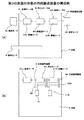
図14及び図15は、第3の実施の形態の用紙搬送装置の一例を示す構成図で、図14(a)は、第3の実施の形態の用紙搬送装置を駆動ローラの側から見た模式的な平面図、図14(b)は、第3の実施の形態の用紙搬送装置を従動ローラの側から見た模式的な平面図である。また、図15(a),図15(b)は、第3の実施の形態の用紙搬送装置を用紙の搬送方向に対する一の側方から見た模式的な側面図である。また、図16は、第3の実施の形態の用紙搬送装置の制御系の一例を示す機能ブロック図である。
<Configuration Example of Paper Conveying Device of Third Embodiment>
FIGS. 14 and 15 are configuration diagrams showing an example of the sheet conveying apparatus according to the third embodiment. FIG. 14A is a diagram illustrating the sheet conveying apparatus according to the third embodiment as viewed from the drive roller side. FIG. 14B is a schematic plan view of the sheet conveying apparatus according to the third embodiment viewed from the driven roller side. FIGS. 15A and 15B are schematic side views of the sheet conveying apparatus according to the third embodiment as viewed from one side with respect to the sheet conveying direction. FIG. 16 is a functional block diagram illustrating an example of a control system of the sheet conveying apparatus according to the third embodiment.
第3の実施の形態の用紙搬送装置1Cは、第1の実施の形態の用紙搬送装置1Aにおいて、給紙ローラ対2L,2Rの間に、用紙Pに対する圧着を解除可能な押さえローラ対8を備える。なお、第3の実施の形態の用紙搬送装置1Cにおいて、押さえローラ対8及び押さえローラ対8に関連する構成以外は、第1の実施の形態の用紙搬送装置1Aと同じ構成であるので、同じ番号を付して詳細な説明は省略する。
The sheet conveying apparatus 1C according to the third embodiment includes a pressing roller pair 8 capable of releasing the pressure bonding to the sheet P between the sheet feeding
押さえローラ対8は、用紙Pの搬送方向に対して中央に配置される非駆動ローラ80と、非駆動ローラ80に対向配置される押さえローラ81を備える。非駆動ローラ80は、駆動ローラ20L及び駆動ローラ20Rと独立した軸に支持されて同軸上に配置される。また、押さえローラ81は、従動ローラ21L及び従動ローラ21Rと独立した軸に支持されて同軸上に配置される。
The pair of pressing rollers 8 includes a non-driving roller 80 disposed in the center with respect to the conveyance direction of the paper P and a pressing roller 81 disposed to face the non-driving roller 80. The non-driving roller 80 is supported on a shaft independent of the driving roller 20L and the driving roller 20R and is arranged coaxially. The pressing roller 81 is supported on a shaft independent of the driven
用紙搬送装置1Cは、押さえローラ対8による用紙Pの挟持及び挟持の解除を行う圧着離間機構9を備える。圧着離間機構9は、押さえローラ対8を構成する非駆動ローラ80と押さえローラ81の何れか、本例では押さえローラ81を、用紙Pに対して圧着及び離間する方向に移動可能に支持する支持部材90を備える。また、圧着離間機構9は、押さえローラ81を用紙Pに対して圧着及び離間する方向に移動させるソレノイド及びバネ等を有した駆動部91を備える。
The
<第3の実施の形態の用紙搬送装置の動作例>
図17は、第3の実施の形態の用紙搬送装置の動作の一例を示すフローチャート、図18は、第3の実施の形態の用紙搬送装置における曲がり補正制御及びシワ補正制御の一例を示す動作説明図で、次に、各図を参照して第3の実施の形態の用紙搬送装置1C及び画像形成装置100Aの動作例について説明する。なお、図18において、用紙Pに対して従動ローラが圧着されている給紙ローラ対及び押さえローラが圧着されている押さえローラ対は実線で示し、従動ローラが離間して圧着が解除されている給紙ローラ対及び押さえローラが離間して圧着が解除されている押さえローラ対は模式的に破線で示している。
<Example of Operation of Paper Conveying Device of Third Embodiment>
FIG. 17 is a flowchart showing an example of the operation of the sheet conveying apparatus of the third embodiment, and FIG. 18 is an explanation of the operation showing an example of the bending correction control and the wrinkle correction control in the sheet conveying apparatus of the third embodiment. Next, operation examples of the sheet conveying apparatus 1C and the
用紙搬送装置1Cは、図4で説明した画像形成装置100Aに組み込まれ、画像形成処理に先立って、制御部6は、ステップSC1の処理で、情報設定部7から紙情報を入手する。そして、制御部6は、ステップSC2の処理で、情報設定部7から入手した紙情報に基づき、図7に示すテーブル300を参照して再圧着フラグNとシワ補正時間Tを設定する。
The paper conveying apparatus 1C is incorporated in the
用紙搬送装置1Cは、画像形成装置100Aの給紙トレイ200内に収容された用紙Pが、給紙部201の分離繰出ローラ202により1枚毎に分離され、給紙ローラ203によって検知センサ5に給紙される。ここで、画像形成装置100Aの給紙トレイ200から用紙Pを給紙する工程では、圧着離間機構9を制御して押さえローラ81を用紙Pに対して離間する位置に退避させ、押さえローラ対8では用紙Pが挟持されない状態とする。
In the sheet conveying apparatus 1C, the sheets P stored in the
制御部6は、ステップSC3の処理で、搬送される用紙Pが曲がっているか否かを検知センサ5の出力から検知し、用紙Pが曲がっている場合は、用紙Pの曲がり量を検知する。
In step SC3, the
制御部6は、検知センサ5の出力から図18(a)に示すように用紙Pが曲がっていると検知すると、ステップSC4の処理で、用紙Pの曲がりを補正する補正制御を行う。用紙Pの曲がり補正制御では、制御部6は、検知センサ5で検知された用紙Pの曲がり量に基づいて、用紙Pの曲がりを補正するために必要な給紙モータ3L及び給紙モータ3Rの駆動時間及び回転数等を設定する。
When detecting that the paper P is bent as shown in FIG. 18A from the output of the
制御部6は、用紙Pの曲がり量に基づき設定された駆動時間及び回転数で給紙モータ3Lと給紙モータ3Rを制御して、駆動ローラ20Lと駆動ローラ20Rの回転速度に差を付けて駆動する。これにより、用紙Pにおいて駆動ローラ20Lによって搬送される搬送方向に対する左側と、駆動ローラ20Rによって搬送される右側で搬送量を異ならせて、図18(b)に二点鎖線で示す状態から、図18(b)に実線で示すように、用紙Pにおいて先行している側と遅延している側の先端位置を揃える。
The
制御部6は、検知センサ5で検知された用紙Pの曲がり量に基づいて給紙モータ3Lと給紙モータ3Rを制御して、用紙Pの曲がりを補正すると、給紙モータ3Lと給紙モータ3Rを制御して、駆動ローラ20Lと駆動ローラ20Rの駆動を停止する。
When the
用紙Pの曲がり補正制御では、用紙Pの幅方向において左右の両側に配置される駆動ローラ20Lと駆動ローラ20Rによる搬送量に差を付けて用紙Pを搬送することで、図18(b)に示すように、用紙Pは幅方向にシワPeが生じる。そこで、ステップSC5の処理で、用紙Pのシワを補正する補正制御を行う。 In the bending correction control of the paper P, the paper P is transported with a difference in the transport amount by the driving roller 20L and the driving roller 20R arranged on both the left and right sides in the width direction of the paper P, so that FIG. As shown, the paper P has wrinkles Pe in the width direction. Therefore, correction control for correcting the wrinkles of the paper P is performed in the process of step SC5.
用紙Pのシワ補正制御では、制御部6は、圧着離間機構4Rを制御して、従動ローラ21Rを用紙Pから離間させる。これにより、用紙Pは、給紙ローラ対2L側では、駆動ローラ20Lと従動ローラ21Lとの間に挟持されて圧着された状態が保持されると共に、給紙ローラ対2R側では、駆動ローラ20Rと従動ローラ21Rによる圧着が解除される。
In the wrinkle correction control for the paper P, the
制御部6は、従動ローラ21Rによる用紙Pの圧着を解除すると、ステップSC6の処理で、用紙Pから離間している押さえローラ81を、圧着離間機構9を制御して用紙Pに圧着させ、用紙Pを非駆動ローラ80と押さえローラ81との間に挟持する。
When the
これにより、曲がり補正制御で用紙Pに発生したシワPeは、用紙Pのコシによる復元力と、曲がり補正制御でシワが発生しやすい用紙Pの中央付近を押さえローラ対8で押さえることで伸ばされ、図18(c)に示すように、用紙Pはシワの無い平らな状態に戻される。 As a result, the wrinkle Pe generated on the paper P by the bending correction control is stretched by pressing the restoring force due to the stiffness of the paper P and the vicinity of the center of the paper P where the wrinkle is easily generated by the bending correction control with the pressing roller pair 8. As shown in FIG. 18C, the paper P is returned to a flat state without wrinkles.
制御部6は、ステップSC7の処理で、再圧着フラグNが従動ローラ21Rによる再圧着有と設定されているか、再圧着無と設定されているかを判断する。
In step SC7, the
制御部6は、再圧着フラグNが従動ローラ21Rによる再圧着有と設定されていると、ステップSC8の処理で、紙情報に基づいて予め設定したシワ補正時間Tが経過した後、圧着離間機構4Rを制御して、従動ローラ21Rで用紙Pを駆動ローラ20Rに圧着する。
If the re-compression flag N is set to be re-compressed by the driven roller 21R, the
そして、制御部6は、ステップSC9の処理で、給紙ローラ対2Lと給紙ローラ対2Rの双方で駆動ローラ20L,20Rと従動ローラ21L,21Rにより用紙Pを挟持した状態で給紙モータ3Lと給紙モータ3Rを制御して、駆動ローラ20Lと駆動ローラ20Rを同速度で駆動し、用紙Pを搬送する。
Then, in the process of step SC9, the
制御部6は、再圧着フラグNが従動ローラ21Rによる再圧着無と設定されていると、ステップSC9の処理で、給紙ローラ対2Lで駆動ローラ20Lと従動ローラ21Lにより用紙Pを挟持した状態で給紙モータ3Lを制御して駆動ローラ20Lを駆動し、用紙Pを搬送する。なお、シワ補正制御後に用紙Pを搬送する工程では、圧着離間機構9を制御して押さえローラ81を用紙Pから離間させ、非駆動ローラ80と押さえローラ81による挟持を解除しても良い。
When the re-compression flag N is set so that the re-compression is not performed by the driven roller 21R, the
画像形成装置100Aでは、中間転写体16上のトナー像との位置が一致するタイミングで、再圧着フラグNに基づいて駆動ローラ20Lまたは駆動ローラ20L,20Rが回転を開始することにより、用紙Pが2次転写部17Aに給紙される。
In the
<第3の実施の形態の用紙搬送装置の他の動作例>
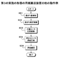
図19は、第3の実施の形態の用紙搬送装置の動作の他の例を示すフローチャートで、次に、各図を参照して第3の実施の形態の用紙搬送装置1C及び画像形成装置100Aの他の動作例について説明する。
<Another example of operation of the sheet conveying apparatus according to the third embodiment>
FIG. 19 is a flowchart illustrating another example of the operation of the sheet conveying apparatus according to the third embodiment. Next, with reference to the drawings, the sheet conveying apparatus 1C and the
用紙搬送装置1Cは、画像形成装置100Aの給紙トレイ200内に収容された用紙Pが、給紙部201の分離繰出ローラ202により1枚毎に分離され、給紙ローラ203によって検知センサ5に給紙される。ここで、画像形成装置100Aの給紙トレイ200から用紙Pを給紙する工程では、圧着離間機構9を制御して押さえローラ81を用紙Pに対して離間する位置に退避させ、押さえローラ対8では用紙Pが挟持されない状態とする。
In the sheet conveying apparatus 1C, the sheets P stored in the
制御部6は、ステップSD1の処理で、搬送される用紙Pが曲がっているか否かを検知センサ5の出力から検知し、用紙Pが曲がっている場合は、用紙Pの曲がり量を検知する。
In step SD1, the
制御部6は、検知センサ5の出力から用紙Pが曲がっていると検知すると、ステップSD2の処理で、用紙Pの曲がりを補正する補正制御を行う。用紙Pの曲がり補正制御では、制御部6は、検知センサ5で検知された用紙Pの曲がり量に基づいて、用紙Pの曲がりを補正するために必要な給紙モータ3L及び給紙モータ3Rの駆動時間及び回転数等を設定する。
When the
制御部6は、用紙Pの曲がり量に基づき設定された駆動時間及び回転数で給紙モータ3Lと給紙モータ3Rを制御して、駆動ローラ20Lと駆動ローラ20Rの回転速度に差を付けて駆動する。これにより、用紙Pにおいて駆動ローラ20Lによって搬送される搬送方向に対する左側と、駆動ローラ20Rによって搬送される右側で搬送量を異ならせて、用紙Pにおいて先行している側と遅延している側の先端位置を揃える。
The
制御部6は、検知センサ5で検知された用紙Pの曲がり量に基づいて給紙モータ3Lと給紙モータ3Rを制御して、用紙Pの曲がりを補正すると、給紙モータ3Lと給紙モータ3Rを制御して、駆動ローラ20Lと駆動ローラ20Rの駆動を停止する。
When the
用紙Pの曲がり補正制御では、用紙Pの幅方向において左右の両側に配置される駆動ローラ20Lと駆動ローラ20Rによる搬送量に差を付けて用紙Pを搬送することで、用紙Pは幅方向にシワが生じる。そこで、ステップSD3の処理で、用紙Pのシワを補正する補正制御を行う。 In the bending correction control of the paper P, the paper P is transported in the width direction by transporting the paper P with a difference in the transport amount by the driving roller 20L and the driving roller 20R arranged on the left and right sides in the width direction of the paper P. Wrinkles occur. Therefore, correction control for correcting the wrinkles of the paper P is performed in the process of step SD3.
用紙Pのシワ補正制御では、制御部6は、圧着離間機構4Rを制御して、従動ローラ21Rを用紙Pから離間させる。これにより、用紙Pは、給紙ローラ対2L側では、駆動ローラ20Lと従動ローラ21Lとの間に挟持された状態が保持されると共に、給紙ローラ対2R側では、駆動ローラ20Rと従動ローラ21Rによる挟持が解除される。
In the wrinkle correction control for the paper P, the
制御部6は、従動ローラ21Rによる用紙Pの圧着を解除すると、ステップSD4の処理で、用紙Pから離間している押さえローラ81を、圧着離間機構9を制御して用紙Pに圧着させ、用紙Pを非駆動ローラ80と押さえローラ81との間に挟持する。
When the
これにより、曲がり補正制御で用紙Pに発生したシワは、用紙Pのコシによる復元力と、曲がり補正制御でシワが発生しやすい用紙Pの中央付近を押さえローラ対8で押さえることで伸ばされ、用紙Pはシワの無い平らな状態に戻される。 Thus, the wrinkles generated on the paper P by the bending correction control are stretched by pressing the restoring force due to the stiffness of the paper P and the vicinity of the center of the paper P where the wrinkles are easily generated by the bending correction control with the pressing roller pair 8. The paper P is returned to a flat state without wrinkles.
制御部6は、シワ補正制御で押さえローラ対8により用紙Pを挟持すると、給紙ローラ対2Lで駆動ローラ20Lと従動ローラ21Lにより用紙Pを挟持した状態で、給紙モータ3Lを制御して駆動ローラ20Lを駆動し、用紙Pを搬送する。シワ補正制御で従動ローラ21Rを用紙Pから離間させたことで、シワ補正制御後の用紙Pの搬送工程では、給紙ローラ対2Rの側では駆動ローラ20Lと従動ローラ21Rにより用紙Pが挟持されていない。ただし、押さえローラ対8で非駆動ローラ80と押さえローラ81で用紙Pを挟持することで、用紙Pの搬送を安定して行える。
When the sheet P is nipped by the pair of pressing rollers 8 in the wrinkle correction control, the
画像形成装置100Aでは、中間転写体16上のトナー像との位置が一致するタイミングで、再圧着フラグNに基づいて駆動ローラ20Lが回転を開始することにより、用紙Pが2次転写部17Aに給紙される。
In the
<第4の実施の形態の用紙搬送装置の構成例>
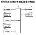
図20及び図21は、第4の実施の形態の用紙搬送装置の一例を示す構成図で、図20(a)は、第4の実施の形態の用紙搬送装置を駆動ローラの側から見た模式的な平面図、図20(b)は、第4の実施の形態の用紙搬送装置を従動ローラの側から見た模式的な平面図である。また、図21(a),図21(b)は、第4の実施の形態の用紙搬送装置を用紙の搬送方向に対する一の側方から見た模式的な側面図である。また、図22は、第4の実施の形態の用紙搬送装置の制御系の一例を示す機能ブロック図である。
<Configuration Example of Paper Conveying Device of Fourth Embodiment>
20 and 21 are configuration diagrams showing an example of the sheet conveying apparatus of the fourth embodiment. FIG. 20A shows the sheet conveying apparatus of the fourth embodiment as viewed from the drive roller side. FIG. 20B is a schematic plan view of the paper conveying device according to the fourth embodiment as viewed from the driven roller side. FIGS. 21A and 21B are schematic side views of the sheet conveying apparatus according to the fourth embodiment as viewed from one side with respect to the sheet conveying direction. FIG. 22 is a functional block diagram illustrating an example of a control system of the sheet conveying apparatus according to the fourth embodiment.
第4の実施の形態の用紙搬送装置1Dは、第2の実施の形態の用紙搬送装置1Bにおいて、給紙ローラ対2L,2Rの間に、用紙Pに対する圧着を解除可能な押さえローラ対8を備える。なお、第4の実施の形態の用紙搬送装置1Dにおいて、押さえローラ対8及び押さえローラ対8に関連する構成以外は、第2の実施の形態の用紙搬送装置1Bと同じ構成であるので、同じ番号を付して詳細な説明は省略する。
In the sheet conveying apparatus 1D of the fourth embodiment, in the sheet conveying apparatus 1B of the second embodiment, a pressing roller pair 8 capable of releasing the pressure bonding to the sheet P is provided between the sheet feeding
押さえローラ対8は、用紙Pの搬送方向に対して中央に配置される非駆動ローラ80と、非駆動ローラ80に対向配置される押さえローラ81を備える。非駆動ローラ80は、駆動ローラ20L及び駆動ローラ20Rと独立した軸に支持されて同軸上に配置される。また、押さえローラ81は、従動ローラ21L及び従動ローラ21Rと独立した軸に支持されて同軸上に配置される。
The pair of pressing rollers 8 includes a non-driving roller 80 disposed in the center with respect to the conveyance direction of the paper P and a pressing roller 81 disposed to face the non-driving roller 80. The non-driving roller 80 is supported on a shaft independent of the driving roller 20L and the driving roller 20R and is arranged coaxially. The pressing roller 81 is supported on a shaft independent of the driven
用紙搬送装置1Dは、押さえローラ対8による用紙Pの挟持及び挟持の解除を行う圧着離間機構9を備える。圧着離間機構9は、押さえローラ対8を構成する非駆動ローラ80と押さえローラ81のいずれか、本例では押さえローラ81を、用紙Pに対して圧着及び離間する方向に移動可能に支持する支持部材90を備える。また、圧着離間機構9は、押さえローラ81を用紙Pに対して圧着及び離間する方向に移動させるソレノイド及びバネ等を有した駆動部91を備える。
The sheet conveying apparatus 1D includes a pressure-bonding / separating mechanism 9 that holds and releases the sheet P by the pressing roller pair 8. The pressure separation / separation mechanism 9 supports either the non-driving roller 80 or the pressure roller 81 constituting the pressure roller pair 8, in this example, the pressure roller 81 movably supported with respect to the paper P in the direction of pressure bonding and separation. A
<第4の実施の形態の用紙搬送装置の動作例>
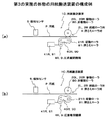
図23は、第4の実施の形態の用紙搬送装置の動作の一例を示すフローチャート、図24及び図25は、第4の実施の形態の用紙搬送装置における曲がり補正制御及びシワ補正制御の一例を示す動作説明図で、次に、各図を参照して第4の実施の形態の用紙搬送装置1D及び画像形成装置100Aの動作例について説明する。なお、図24及び図25において、用紙Pに対して従動ローラが圧着されている給紙ローラ対及び押さえローラが圧着されている押さえローラ対は実線で示し、従動ローラが離間して圧着が解除されている給紙ローラ対及び押さえローラが離間して圧着が解除されている押さえローラ対は模式的に破線で示している。
<Operation Example of Paper Conveying Device of Fourth Embodiment>
FIG. 23 is a flowchart showing an example of the operation of the sheet conveying apparatus of the fourth embodiment. FIGS. 24 and 25 are examples of the bending correction control and the wrinkle correction control in the sheet conveying apparatus of the fourth embodiment. Next, operation examples of the sheet conveying apparatus 1D and the
用紙搬送装置1Dは、画像形成装置100Aの給紙トレイ200内に収容された用紙Pが、給紙部201の分離繰出ローラ202により1枚毎に分離され、給紙ローラ203によって検知センサ5に給紙される。ここで、画像形成装置100Aの給紙トレイ200から用紙Pを給紙する工程では、圧着離間機構9を制御して押さえローラ81を用紙Pに対して離間する位置に退避させ、押さえローラ対8では用紙Pが挟持されない状態とする。
In the sheet conveying apparatus 1D, the sheets P stored in the
制御部6は、ステップSE1の処理で、搬送される用紙Pが曲がっているか否かを検知センサ5の出力から検知し、用紙Pが曲がっている場合は、用紙Pの曲がり量と曲がり方向を検知する。
In the process of step SE1, the
制御部6は、ステップSE2の処理で、シワ補正制御で従動ローラ21Lと従動ローラ21Rのどちらを用紙Pから離間させて、用紙Pに対する圧着を解除するか、検知センサ5で検知された用紙Pの曲がり方向に基づき選択する。
In the process of step SE2, the
例えば、検知センサ5で検知された用紙Pの曲がり方向が、図24(a)に示すように、用紙Pの搬送方向に対して右側が先行する右先行の場合は、シワ補正制御で用紙Pに対する圧着を解除する従動ローラとして、従動ローラ21Rが選択される。一方、用紙Pの曲がり方向が、図25(a)に示すように左先行の場合は、シワ補正制御で用紙Pに対する圧着を解除する従動ローラとして、従動ローラ21Lが選択される。
For example, when the bending direction of the paper P detected by the
制御部6は、検知センサ5の出力から用紙Pが曲がっていると検知すると、ステップSE3の処理で、用紙Pの曲がり補正制御を行う。用紙Pの曲がり補正制御では、制御部6は、検知センサ5で検知された用紙Pの曲がり量と曲がり方向に基づいて、用紙Pの曲がりを補正するために必要な給紙モータ3L及び給紙モータ3Rの駆動時間及び回転数等を設定する。
When the
制御部6は、用紙Pの曲がり量と曲がり方向に基づき設定された駆動時間及び回転数で給紙モータ3Lと給紙モータ3Rを制御して、駆動ローラ20Lと駆動ローラ20Rの回転速度に差を付けて駆動する。これにより、用紙Pにおいて駆動ローラ20Lによって搬送される搬送方向に対する左側と、駆動ローラ20Rによって搬送される右側で搬送量を異ならせて、用紙Pにおいて先行している側と遅延している側の先端位置を揃える。
The
例えば、検知センサ5で検知された用紙Pの曲がり方向が、図24(a)に示すように右先行の場合は、用紙Pの先行している側の駆動ローラ20Rの駆動は停止し、用紙Pの遅延している側の駆動ローラ20Lを駆動する。または、駆動ローラ20Rを駆動ローラ20Lより低速で駆動する。これにより、駆動ローラ20Lと駆動ローラ20Rによる搬送量に差を付けて、図24(b)に二点鎖線で示す状態から、図24(b)に実線で示すように、用紙Pにおいて先行している右側の先端位置に遅延している左側の先端位置を揃える。
For example, when the bending direction of the paper P detected by the
一方、検知センサ5で検知された用紙Pの曲がり方向が、図25(a)に示すように左先行の場合は、用紙Pの先行している側の駆動ローラ20Lの駆動は停止し、用紙Pの遅延している側の駆動ローラ20Rを駆動する。または、駆動ローラ20Lを駆動ローラ20Rより低速で駆動する。これにより、駆動ローラ20Lと駆動ローラ20Rによる搬送量に差を付けて、図25(b)に二点鎖線で示す状態から、図25(b)に実線で示すように、用紙Pにおいて先行している左側の先端位置に遅延している右側の先端位置を揃える。
On the other hand, when the bending direction of the paper P detected by the
制御部6は、検知センサ5で検知された用紙Pの曲がり量と曲がり方向に基づいて給紙モータ3Lと給紙モータ3Rを制御して、用紙Pの曲がりを補正すると、給紙モータ3Lと給紙モータ3Rを制御して、駆動ローラ20Lと駆動ローラ20Rの駆動を停止する。
When the
用紙Pの曲がり補正制御では、用紙Pの幅方向において左右の両側に配置される駆動ローラ20Lと駆動ローラ20Rによる搬送量に差を付けて用紙Pを搬送することで、図24(b)及び図25(b)に示すように、用紙Pは幅方向にシワPeが生じる。そこで、ステップSE4の処理で、用紙Pのシワを補正する補正制御を行う。 In the bending correction control of the paper P, the paper P is transported with a difference in the transport amount by the driving roller 20L and the driving roller 20R arranged on both the left and right sides in the width direction of the paper P, and FIG. As shown in FIG. 25B, the paper P has wrinkles Pe in the width direction. Therefore, correction control for correcting the wrinkles of the paper P is performed in the process of step SE4.
用紙Pのシワ補正制御では、制御部6は、検知センサ5で検知された用紙Pの曲がり方向に基づき上述したステップSE2の処理で選択された従動ローラを用紙Pから離間させて、曲がり補正制御によってシワが発生した側の従動ローラによる用紙Pに対する圧着を解除する。
In the wrinkle correction control of the paper P, the
例えば、検知センサ5で検知された用紙Pの曲がり方向が右先行であると、制御部6は、図24(b)に示すように圧着離間機構4Rを制御して、従動ローラ21Rを用紙Pから離間させる。これにより、用紙Pは、給紙ローラ対2L側では、駆動ローラ20Lと従動ローラ21Lとの間に挟持されて圧着された状態が保持されると共に、給紙ローラ対2R側では、駆動ローラ20Rと従動ローラ21Rによる圧着が解除される。
For example, if the bending direction of the paper P detected by the
一方、検知センサ5で検知された用紙Pの曲がり方向が左先行であると、制御部6は、図25(b)に示すように圧着離間機構4Lを制御して、従動ローラ21Lを用紙Pから離間させる。これにより、用紙Pは、給紙ローラ対2R側では、駆動ローラ20Rと従動ローラ21Rとの間に挟持されて圧着された状態が保持されると共に、給紙ローラ対2L側では、駆動ローラ20Lと従動ローラ21Lによる圧着が解除される。
On the other hand, if the bending direction of the paper P detected by the
制御部6は、用紙Pの曲がり方向に基づき従動ローラ21Lまたは従動ローラ21Rによる用紙Pの圧着を解除すると、ステップSE5の処理で、用紙Pから離間している押さえローラ81を、圧着離間機構9を制御して用紙Pに圧着させ、用紙Pを非駆動ローラ80と押さえローラ81との間に挟持する。
When the
これにより、曲がり補正制御で用紙Pに発生したシワPeは、用紙Pのコシによる復元力と、曲がり補正制御でシワが発生しやすい用紙Pの中央付近を押さえローラ対8で押さえることで伸ばされ、図24(c)及び図25(c)に示すように、用紙Pはシワの無い平らな状態に戻される。 As a result, the wrinkle Pe generated on the paper P by the bending correction control is stretched by pressing the restoring force due to the stiffness of the paper P and the vicinity of the center of the paper P where the wrinkle is easily generated by the bending correction control with the pressing roller pair 8. 24 (c) and 25 (c), the paper P is returned to a flat state without wrinkles.
制御部6は、シワ補正制御で押さえローラ対8により用紙Pを挟持すると、ステップSE6の処理で、給紙ローラ対2Lまたは給紙ローラ対2Rで駆動ローラと従動ローラにより用紙Pを挟持した状態で、給紙モータ3Lまたは給紙モータ3Rを制御して駆動ローラ20Lまたは駆動ローラ20Rを駆動し、用紙Pを搬送する。シワ補正制御で従動ローラ21Lまたは従動ローラ21Rを用紙Pから離間させたことで、シワ補正制御後の用紙Pの搬送工程では、一方の給紙ローラ対の側では駆動ローラと従動ローラにより用紙Pが挟持されていない。ただし、押さえローラ対8で非駆動ローラ80と押さえローラ81で用紙Pを挟持することで、用紙Pの搬送を安定して行える。
When the sheet P is held by the pressing roller pair 8 by the wrinkle correction control, the
画像形成装置100Aでは、中間転写体16上のトナー像との位置が一致するタイミングで、再圧着フラグNに基づいて駆動ローラ20Lまたは駆動ローラ20R、あるいは駆動ローラ20Lと駆動ローラ20Rの双方が回転を開始することにより、用紙Pが2次転写部17Aに給紙される。
In the
本発明は、用紙の斜行を補正する機能を有した画像形成装置に適用される。 The present invention is applied to an image forming apparatus having a function of correcting skew of a sheet.
1A〜1D・・・用紙搬送装置、2L,2R・・・給紙ローラ対、20L,20R・・・駆動ローラ、21L,21R・・・従動ローラ、3L,3R・・・給紙モータ、4L,4R・・・圧着離間機構、5・・・検知センサ、6・・・制御部、7・・・情報設定部、8・・・押さえローラ対、80・・・非駆動ローラ、81・・・押さえローラ、9・・・圧着離間機構 1A to 1D: Paper transport device, 2L, 2R: Paper feed roller pair, 20L, 20R: Drive roller, 21L, 21R: Driven roller, 3L, 3R: Paper feed motor, 4L , 4R: pressure separation mechanism, 5: detection sensor, 6: control unit, 7: information setting unit, 8: press roller pair, 80: non-driving roller, 81.・ Pressing roller, 9 ... Pressing and separating mechanism
Claims (7)
前記駆動ローラを独立して駆動する給紙モータと、
前記駆動ローラまたは前記従動ローラを、用紙に対して離接する方向に移動させ、少なくとも一方の前記給紙ローラ対を、用紙に対して離間及び圧着させる圧着離間機構と、
用紙が曲がっているか否かを検知する検知センサと、
前記給紙モータを制御して前記駆動ローラで用紙を搬送し、用紙の搬送方向に対する左右で搬送量を異ならせて、前記検知センサで検知された用紙の曲がりを補正する曲がり補正制御と、前記圧着離間機構を制御して一方の前記給紙ローラ対を用紙から離間させ、曲がり補正制御で発生した用紙のシワを、用紙の復元力で元に戻すシワ補正制御を行う制御部と
を備えたことを特徴とする用紙搬送装置。 A pair of paper feed rollers having at least two drive rollers arranged in parallel on the left and right with respect to the paper conveyance direction and driven rollers respectively facing the drive rollers;
A paper feed motor for independently driving the drive roller;
A pressure-separation separation mechanism that moves the driving roller or the driven roller in a direction in which the driving roller or the driven roller is separated from or contacted with the paper, and separates and presses at least one of the paper feeding roller pairs with respect to the paper;
A detection sensor for detecting whether the paper is bent,
Bending correction control for controlling the sheet feeding motor to convey the sheet with the driving roller, and varying the amount of conveyance on the right and left with respect to the sheet conveying direction to correct the bending of the sheet detected by the detection sensor; A control unit that controls the pressure-separation mechanism to separate one of the pair of paper feed rollers from the paper, and performs wrinkle correction control that restores the wrinkle of the paper generated by the bending correction control to the original by the restoring force of the paper. A sheet conveying apparatus characterized by the above.
前記制御部は、前記検知センサで検知される用紙の曲がり方向に基づき、シワ補正制御で用紙から離間させる前記給紙ローラ対を選択して前記圧着離間機構を制御し、用紙の曲がり方向に応じた一方の前記給紙ローラ対を用紙から離間させてシワ補正制御を行う
ことを特徴とする請求項1記載の用紙搬送装置。 The pair of paper feed rollers arranged side by side with respect to the paper transport direction are each provided with the pressure-bonding separation mechanism.
The control unit selects the paper feed roller pair to be separated from the paper by the wrinkle correction control based on the paper bending direction detected by the detection sensor and controls the pressure-bonding separation mechanism, and according to the paper bending direction. The sheet conveying apparatus according to claim 1, wherein wrinkle correction control is performed by separating the other pair of sheet feeding rollers from the sheet.
ことを特徴とする請求項1または2記載の用紙搬送装置。 The control unit holds one of the paper feed roller pairs separated from the sheet by the wrinkle correction control in a state of being separated from the sheet and the other of the other of the two of the paper rollers held in a state of being crimped to the sheet by the wrinkle correction control. The sheet conveying apparatus according to claim 1, wherein the sheet that has undergone the bending correction control and the wrinkle correction control is conveyed by the pair of sheet feeding rollers.
ことを特徴とする請求項1または2記載の用紙搬送装置。 The control unit re-compresses one of the paper feed roller pairs separated from the paper by the wrinkle correction control, and the one paper feed roller pair re-compressed to the paper after the wrinkle correction control and the wrinkle correction control. 3. The paper conveying apparatus according to claim 1, wherein the paper having undergone the bending correction control and the wrinkle correction control is conveyed by the other pair of paper feed rollers held in a state of being pressed against the paper. .
前記制御部は、シワ補正制御で用紙から離間させた一方の前記給紙ローラ対による再圧着の有無と、用紙から離間させた前記給紙ローラ対による再圧着をする場合に、再圧着するまでの補正時間を、前記情報設定部で設定された紙種情報に基づいて判断し、
再圧着をしないと判断した場合は、シワ補正制御で用紙から離間させた一方の前記給紙ローラ対を、用紙から離間させた状態で保持し、シワ補正制御で用紙に圧着させた状態に保持された他方の前記給紙ローラ対で、曲がり補正制御及びシワ補正制御が行われた用紙を搬送し、
再圧着をすると判断した場合は、シワ補正制御で用紙から離間させた一方の前記給紙ローラ対を、予め設定された補正時間に従い用紙に再圧着させ、シワ補正制御後に用紙に再圧着された一方の前記給紙ローラ対、及びシワ補正制御で用紙に圧着させた状態に保持された他方の前記給紙ローラ対で、曲がり補正制御及びシワ補正制御が行われた用紙を搬送する
ことを特徴とする請求項1または2記載の用紙搬送装置。 It has an information setting section that sets the paper type information of the paper,
The control unit determines whether or not re-compression is performed by the one pair of paper feed rollers separated from the paper by the wrinkle correction control, and when re-compression is performed by the pair of paper feed rollers separated from the paper. Is determined based on the paper type information set in the information setting unit,
If it is determined that re-crimping will not be performed, the pair of paper feed rollers separated from the paper by wrinkle correction control is held in a state of being separated from the paper, and held in a state of being crimped to the paper by wrinkle correction control. The other pair of paper feed rollers is used to transport the paper subjected to the bending correction control and the wrinkle correction control,
If it is determined that re-crimping is performed, the pair of paper feed rollers separated from the paper by the wrinkle correction control is re-press-bonded to the paper in accordance with a preset correction time, and is re-press-bonded to the paper after the wrinkle correction control. One of the pair of paper feed rollers and the other pair of paper feed rollers held in a state of being pressed against the paper by the wrinkle correction control convey the paper subjected to the bending correction control and the wrinkle correction control. The sheet conveying apparatus according to claim 1 or 2.
前記非駆動ローラまたは前記押さえローラを、用紙に対して離接する方向に移動させ、前記押さえローラ対を、用紙に対して離間及び圧着させる押さえローラ圧着離間機構とを備え、
前記制御部は、用紙から離間させた前記押さえローラ対を、シワ補正制御で一方の前記給紙ローラ対を用紙から離間させると、用紙に圧着させる
ことを特徴とする請求項1〜5に何れか記載の用紙搬送装置。 A pair of pressing rollers disposed between the pair of paper feed rollers juxtaposed in the right and left of the sheet conveying direction, having a non-driving roller coaxially with the driving roller, and having a pressing roller coaxial with the driven roller. When,
A non-driving roller or the pressing roller is moved in a direction in which the non-driving roller is separated from or contacted with the paper, and the pressing roller pair is separated and pressed against the paper;
6. The control unit according to any one of claims 1 to 5, wherein the control unit causes the pair of pressing rollers separated from the sheet to be pressed against the sheet when the one sheet feeding roller pair is separated from the sheet by wrinkle correction control. Or a paper conveying device.
前記画像形成部に用紙を搬送する用紙搬送装置を備え、
前記用紙搬送装置は、
用紙の搬送方向に対して左右に並列され、同軸上に配置される少なくとも2個の駆動ローラ及び前記駆動ローラとそれぞれ対向する従動ローラを有した給紙ローラ対と、
前記駆動ローラを独立して駆動する給紙モータと、
前記駆動ローラまたは前記従動ローラを、用紙に対して離接する方向に移動させ、少なくとも一方の前記給紙ローラ対を、用紙に対して離間及び圧着させる圧着離間機構と、
用紙が曲がっているか否かを検知する検知センサと、
前記給紙モータを制御して前記駆動ローラで用紙を搬送し、用紙の搬送方向に対する左右で搬送量を異ならせて、前記検知センサで検知された用紙の曲がりを補正する曲がり補正制御と、前記圧着離間機構を制御して一方の前記給紙ローラ対を用紙から離間させ、曲がり補正制御で発生した用紙のシワを、用紙の復元力で元に戻すシワ補正制御を行う制御部とを備えた
ことを特徴とする画像形成装置。 An image forming unit for forming an image on paper;
A paper transport device for transporting paper to the image forming unit;
The paper conveying device is
A pair of paper feed rollers having at least two drive rollers arranged in parallel on the left and right with respect to the paper conveyance direction and driven rollers respectively facing the drive rollers;
A paper feed motor for independently driving the drive roller;
A pressure-separation separation mechanism that moves the driving roller or the driven roller in a direction in which the driving roller or the driven roller is separated from or contacted with the paper, and separates and presses at least one of the paper feeding roller pairs with respect to the paper;
A detection sensor for detecting whether the paper is bent,
Bending correction control for controlling the sheet feeding motor to convey the sheet with the driving roller, and varying the amount of conveyance on the right and left with respect to the sheet conveying direction to correct the bending of the sheet detected by the detection sensor; A control unit that controls the crimping separation mechanism to separate one of the pair of paper feed rollers from the paper, and performs wrinkle correction control that restores the wrinkles of the paper generated by the bending correction control to the original by the restoring force of the paper. An image forming apparatus.
Priority Applications (1)
| Application Number | Priority Date | Filing Date | Title |
|---|---|---|---|
| JP2008207989A JP5045604B2 (en) | 2008-08-12 | 2008-08-12 | Paper conveying apparatus and image forming apparatus |
Applications Claiming Priority (1)
| Application Number | Priority Date | Filing Date | Title |
|---|---|---|---|
| JP2008207989A JP5045604B2 (en) | 2008-08-12 | 2008-08-12 | Paper conveying apparatus and image forming apparatus |
Publications (2)
| Publication Number | Publication Date |
|---|---|
| JP2010042903A true JP2010042903A (en) | 2010-02-25 |
| JP5045604B2 JP5045604B2 (en) | 2012-10-10 |
Family
ID=42014622
Family Applications (1)
| Application Number | Title | Priority Date | Filing Date |
|---|---|---|---|
| JP2008207989A Expired - Fee Related JP5045604B2 (en) | 2008-08-12 | 2008-08-12 | Paper conveying apparatus and image forming apparatus |
Country Status (1)
| Country | Link |
|---|---|
| JP (1) | JP5045604B2 (en) |
Cited By (2)
| Publication number | Priority date | Publication date | Assignee | Title |
|---|---|---|---|---|
| JP2019038676A (en) * | 2017-08-28 | 2019-03-14 | コニカミノルタ株式会社 | Paper conveying apparatus and image forming apparatus |
| US10384893B2 (en) | 2017-03-22 | 2019-08-20 | Canon Finetech Nisca Inc. | Sheet conveying apparatus, image reading apparatus, and image forming apparatus |
-
2008
- 2008-08-12 JP JP2008207989A patent/JP5045604B2/en not_active Expired - Fee Related
Cited By (3)
| Publication number | Priority date | Publication date | Assignee | Title |
|---|---|---|---|---|
| US10384893B2 (en) | 2017-03-22 | 2019-08-20 | Canon Finetech Nisca Inc. | Sheet conveying apparatus, image reading apparatus, and image forming apparatus |
| JP2019038676A (en) * | 2017-08-28 | 2019-03-14 | コニカミノルタ株式会社 | Paper conveying apparatus and image forming apparatus |
| JP6996165B2 (en) | 2017-08-28 | 2022-01-17 | コニカミノルタ株式会社 | Paper transfer device and image forming device |
Also Published As
| Publication number | Publication date |
|---|---|
| JP5045604B2 (en) | 2012-10-10 |
Similar Documents
| Publication | Publication Date | Title |
|---|---|---|
| JP5445510B2 (en) | Conveying apparatus and image forming apparatus | |
| EP3543186B1 (en) | Sheet processing apparatus and image forming system incorporating the same | |
| US7422209B2 (en) | Sheet conveying apparatus and image forming apparatus | |
| JP2019163121A (en) | Sheet processing device and image formation system | |
| CN107010466A (en) | After-treatment device and the image processing system for possessing the after-treatment device | |
| JP6128829B2 (en) | Post-processing apparatus and control method thereof | |
| JP5045604B2 (en) | Paper conveying apparatus and image forming apparatus | |
| US20210403262A1 (en) | Sheet conveying apparatus | |
| JP2006036493A (en) | Sheet handling device and image forming device equipped with it | |
| JP5887951B2 (en) | Image forming apparatus | |
| CN107703723B (en) | Image forming apparatus | |
| JP5825098B2 (en) | Paper conveying apparatus and image forming apparatus | |
| JP5895555B2 (en) | Image forming apparatus | |
| JP6561898B2 (en) | Image forming apparatus | |
| JP2008081251A (en) | Sheet conveyance system | |
| JP2005162384A (en) | Registration device, image forming device using it, and image reading device | |
| JP2009120333A (en) | Sheet conveying device and image forming device | |
| JP5321073B2 (en) | Paper conveying apparatus and image forming apparatus | |
| JP2009029618A (en) | Paper post-processing device and paper post-processing method | |
| JP2014118235A (en) | Sheet folding device, image formation apparatus, and image formation system | |
| JP4973518B2 (en) | Image forming apparatus | |
| JP2017171505A (en) | Sheet folding device, image formation apparatus, image formation system and sheet folding method | |
| JP6380322B2 (en) | Image forming apparatus | |
| JP2007119091A (en) | Recording medium delivery device and image forming device | |
| JP2009083965A (en) | Post-processing device and image forming system |
Legal Events
| Date | Code | Title | Description |
|---|---|---|---|
| A621 | Written request for application examination |
Free format text: JAPANESE INTERMEDIATE CODE: A621 Effective date: 20110207 |
|
| RD02 | Notification of acceptance of power of attorney |
Free format text: JAPANESE INTERMEDIATE CODE: A7422 Effective date: 20110913 |
|
| A977 | Report on retrieval |
Free format text: JAPANESE INTERMEDIATE CODE: A971007 Effective date: 20120614 |
|
| TRDD | Decision of grant or rejection written | ||
| A01 | Written decision to grant a patent or to grant a registration (utility model) |
Free format text: JAPANESE INTERMEDIATE CODE: A01 Effective date: 20120619 |
|
| A01 | Written decision to grant a patent or to grant a registration (utility model) |
Free format text: JAPANESE INTERMEDIATE CODE: A01 |
|
| A61 | First payment of annual fees (during grant procedure) |
Free format text: JAPANESE INTERMEDIATE CODE: A61 Effective date: 20120702 |
|
| FPAY | Renewal fee payment (event date is renewal date of database) |
Free format text: PAYMENT UNTIL: 20150727 Year of fee payment: 3 |
|
| R150 | Certificate of patent or registration of utility model |
Free format text: JAPANESE INTERMEDIATE CODE: R150 |
|
| S111 | Request for change of ownership or part of ownership |
Free format text: JAPANESE INTERMEDIATE CODE: R313111 |
|
| R350 | Written notification of registration of transfer |
Free format text: JAPANESE INTERMEDIATE CODE: R350 |
|
| LAPS | Cancellation because of no payment of annual fees |