JP2010042874A - Garbage container for separation - Google Patents
Garbage container for separation Download PDFInfo
- Publication number
- JP2010042874A JP2010042874A JP2008206149A JP2008206149A JP2010042874A JP 2010042874 A JP2010042874 A JP 2010042874A JP 2008206149 A JP2008206149 A JP 2008206149A JP 2008206149 A JP2008206149 A JP 2008206149A JP 2010042874 A JP2010042874 A JP 2010042874A
- Authority
- JP
- Japan
- Prior art keywords
- container
- garbage
- container body
- lid
- waste
- Prior art date
- Legal status (The legal status is an assumption and is not a legal conclusion. Google has not performed a legal analysis and makes no representation as to the accuracy of the status listed.)
- Granted
Links
Images


Classifications
-
- Y—GENERAL TAGGING OF NEW TECHNOLOGICAL DEVELOPMENTS; GENERAL TAGGING OF CROSS-SECTIONAL TECHNOLOGIES SPANNING OVER SEVERAL SECTIONS OF THE IPC; TECHNICAL SUBJECTS COVERED BY FORMER USPC CROSS-REFERENCE ART COLLECTIONS [XRACs] AND DIGESTS
- Y02—TECHNOLOGIES OR APPLICATIONS FOR MITIGATION OR ADAPTATION AGAINST CLIMATE CHANGE
- Y02W—CLIMATE CHANGE MITIGATION TECHNOLOGIES RELATED TO WASTEWATER TREATMENT OR WASTE MANAGEMENT
- Y02W30/00—Technologies for solid waste management
- Y02W30/10—Waste collection, transportation, transfer or storage, e.g. segregated refuse collecting, electric or hybrid propulsion
Landscapes
- Refuse Receptacles (AREA)
Abstract
Description
本発明は、ごみを分別して廃棄・回収可能な分別用ごみ容器に関する。 The present invention relates to a separation waste container that can separate and dispose of and collect waste.
近年、ごみを分別し、可燃ごみと不燃ごみとを分けて廃棄するだけでなく、リサイクルの可能なごみを資源ごみとして回収することが一般化している。特に、毎日多くの人が利用する駅や公共施設、また商業施設やオフィスビルなどのように、多量のごみが出される場所では、ごみを可燃ごみ、不燃ごみ、ビン、缶、ペットボトル等の種類別に分別して回収するように、専用のごみ容器を設置することが重要となっている。 In recent years, it has become common not only to separate garbage and separate and dispose of combustible waste and non-burnable waste, but also to collect recyclable waste as resource waste. Especially in places where a lot of garbage is taken out, such as stations, public facilities, commercial facilities, and office buildings that many people use every day, such as combustible waste, non-combustible waste, bottles, cans, plastic bottles, etc. It is important to install a dedicated waste container so that it can be collected by type.
多数の人が容易にごみを分別して廃棄できるようにしておくには、設置するごみ容器に、その容器に投入すべきごみの種類をわかりやすく示し、また、分別を無視したごみの投入を防ぐ必要がある。そこで、回収するごみの種類ごとに表示し、ごみの投入口の形状を異なるものとしたり、ごみ容器や投入口の色を変えたりする工夫がなされている。 In order to make it easy for many people to separate and dispose of garbage, the garbage container to be installed should be clearly marked with the type of garbage that should be thrown into the container, and it should be avoided There is a need. In view of this, a device has been devised in which the type of garbage to be collected is displayed and the shape of the garbage inlet is made different, or the color of the garbage container or the inlet is changed.
しかし、一箇所で複数種類のごみをそれぞれ分別して回収するには、分別する種類に対応する個数のごみ容器を設置しておかなければならず、ごみ容器の設置に場所をとってしまうため、給湯室や休憩室のように狭い場所であっても設置できる分別用のごみ容器であることが必要とされた。 However, in order to separate and collect multiple types of garbage at one place, it is necessary to install as many garbage containers as the types to be sorted, and it takes up space to install the garbage containers. It was necessary to be a garbage container for separation that can be installed even in a small place such as a hot water supply room or a break room.
分別用のごみ容器として、例えば、特許文献1には、普通ごみを収容する第1ごみ容器と、空き缶等の回収ごみを収容する第2ごみ容器とを、上下二段に積み上げた構造のごみ容器について記載されている。このような構成により、狭い場所あっても2種類のごみを回収できるように意図されている。
前記従来のごみ容器の場合、上下二段にごみ容器を積み上げた構成であるので、それぞれの容器の容量があまり大きくなく、ペットボトルなどのように嵩ばるごみであれば、容器がすぐにいっぱいになってしまうという問題点がある。また、ごみ容器に投入されたごみを回収するには、下段のごみは上段のごみ容器を取り除かなければ作業できず、手間がかかるものである。さらに、このような分別用のごみ容器を設置するに際し、新規のごみ容器を購入するだけでなく、できるだけ既設のごみ容器を利用して、ごみを分別できるようにすることが、環境面を考慮してもより望ましいものとなる。 In the case of the conventional garbage container, since the garbage containers are stacked in two upper and lower stages, the capacity of each container is not so large, and if the garbage is bulky, such as PET bottles, the container is filled quickly. There is a problem of becoming. Moreover, in order to collect the waste thrown into the waste container, the lower waste cannot be worked unless the upper waste container is removed, which is troublesome. Furthermore, when installing such a waste container for separation, not only purchasing a new waste container but also using existing waste containers as much as possible so that the waste can be separated in consideration of the environment. Even more desirable.
そこで、本発明は、上記のような問題点にかんがみてなされたものであり、一つのごみ容器で複数種類のごみの分別投入を可能として少ないスペースでも設置でき、ごみ容器の中に取り付ける回収用の内袋も、分別数に対応させて複数枚をきちんと保持できるようにするとともに、ごみの回収や内袋の取り替え作業も容易に行える構造とし、また、既設のごみ容器をそのまま利用することも可能な分別用のごみ容器を提供するものである。 Therefore, the present invention has been made in view of the above-mentioned problems, and can be installed in a small space so that a plurality of types of garbage can be separated and fed into one garbage container, and can be installed in a garbage container. The inner bag also has a structure that can hold multiple sheets properly according to the number of separation, can easily collect and replace the inner bag, and can use the existing waste container as it is A possible waste container is provided.
上記した目的を達成するため、本発明に係るごみ容器は、上部が開口して内側にごみ回収用の内袋が収容される容器本体と、ごみの投入口を備えて前記容器本体の上部に取り付けられる蓋体を有し、前記蓋体は、片流れ状に形成された傾斜面を備え、この傾斜面の傾斜流れ方向に複数個の投入口が配列されており、前記容器本体は、投入口の配置に対応させて複数の内袋を保持しうる袋取付部材が備えられて、これらの内袋により内部が区画されることを特徴とする。このような発明により、一つのごみ容器で複数種類のごみの分別投入を可能とし、省スペースでも設置することができる。 In order to achieve the above-described object, a garbage container according to the present invention includes a container body in which an upper part is opened and an inner bag for collecting garbage is accommodated inside, and a garbage input port provided at an upper part of the container body. The lid body has an inclined surface formed in a single flow shape, and a plurality of input ports are arranged in the inclined flow direction of the inclined surface. A bag attaching member capable of holding a plurality of inner bags corresponding to the arrangement of the inner bag is provided, and the inside is partitioned by these inner bags. According to such an invention, it is possible to separate and input a plurality of types of garbage in one garbage container, and it can be installed even in a space-saving manner.
前記構成において、前記容器本体は隅部にアールを設けた略直方体形状の外形状に形成されるとともに、上部開口の長辺方向に沿って前記蓋体の傾斜面が設けられて、容器本体の内部が上部開口の長辺方向を分割するように区画されていることが好ましい。 In the above configuration, the container body is formed in a substantially rectangular parallelepiped outer shape with rounded corners, and an inclined surface of the lid body is provided along the long side direction of the upper opening. It is preferable that the inside is partitioned so as to divide the long side direction of the upper opening.
また、本発明において、前記蓋体の投入口は、蓋体の傾斜面に形成された互いに同形状の複数個の開口孔に、投入口が開設された着脱自在な投入口部材を装着して設けられることが好ましい。これにより、使用者の求めに応じて多様な分別形態のごみの回収が可能となる。 Further, in the present invention, the insertion port of the lid body is provided with a detachable insertion port member provided with an insertion port in a plurality of openings having the same shape formed on the inclined surface of the lid body. It is preferable to be provided. This makes it possible to collect various types of waste according to the user's request.
より詳細には、前記投入口部材は、略円形あるいは楕円形の投入口、略矩形の投入口、または開閉蓋付きの投入口のいずれかが形成されていることが好ましい。このように、投入口の形状を異ならせることにより、投入を許容するごみの種類を限定し、また使用者にもごみの分別をわかりやすく示すことが可能となる。 More specifically, the charging port member is preferably formed with either a substantially circular or elliptical loading port, a substantially rectangular loading port, or a loading port with an opening / closing lid. In this way, by changing the shape of the input port, it is possible to limit the types of waste that are allowed to be input, and to easily show the user how to separate the waste.
また、本発明では、前記袋取付部材は、容器本体の上部開口縁の内側に沿って配設される押さえ枠と、容器本体の対向する側面間上部に架け渡される仕切材とを備え、前記仕切材は、一体とされた平行板材に内袋の端部を係止可能な凸部が設けられて、平行板材間に内袋の端部を折り返して係止させるとともに、前記押さえ枠にて前記内袋を容器本体の上部開口縁の内側に沿って保持することを特徴とする。 Further, in the present invention, the bag mounting member includes a holding frame disposed along the inside of the upper opening edge of the container body, and a partition member spanned between the upper portions of the container bodies facing each other, The partition member is provided with a convex portion capable of locking the end portion of the inner bag on the integrated parallel plate material, and the end portion of the inner bag is folded and locked between the parallel plate materials, and the holding frame The inner bag is held along the inner side of the upper opening edge of the container body.
さらに、前記仕切材は、その両端部を、容器本体の上部開口縁における対向する内側面にそれぞれ固着される固定部に固定しうる構造を有し、各固定部には、仕切材の端部を嵌入可能な固定孔が複数個配設されていることが好ましい。このような構成により、容器本体に内袋を好適に設置でき、作業性が高められるとともに、ごみの許容量に可変性をもたせることが可能となる。 Further, the partition member has a structure capable of fixing both end portions thereof to fixing portions respectively fixed to opposing inner side surfaces of the upper opening edge of the container body, and each fixing portion includes an end portion of the partition member. It is preferable that a plurality of fixing holes into which can be inserted are provided. With such a configuration, the inner bag can be suitably installed in the container body, the workability can be improved, and the allowable amount of waste can be made variable.
また、本発明では、前記容器本体は、さらに、隣接して並べられた他の容器本体と一体に結合可能な連結部材を備え、この連結部材は、隣接する容器本体の上部開口縁にそれぞれ嵌着されて挟持する二つの挟持部と、これらの挟持部間に設けられて隣接する蓋体の取付クリアランスを形成する溝部とを有することを特徴とする。これにより、複数個のごみ容器を一箇所に安定的に設置することができ、また連結されたごみ容器同士を離すことも容易であり、より多様な使用形態に対応することが可能となる。 In the present invention, the container main body further includes a connecting member that can be integrally coupled to another adjacent container main body, and the connecting member is fitted to each upper opening edge of the adjacent container main body. It is characterized by having two sandwiching portions that are worn and sandwiched, and a groove portion that is provided between these sandwiching portions and that forms an attachment clearance between adjacent lids. Thereby, a plurality of garbage containers can be stably installed at one place, and the connected garbage containers can be easily separated from each other, so that it is possible to cope with various usage forms.
上述のように構成される本発明の分別用ごみ容器によれば、一つのごみ容器で複数種類のごみの分別投入を可能とすることができ、少ないスペースでも設置することが可能である。また、ごみ容器の中にセットする内袋も、分別数に対応させて複数枚をきちんと保持することができ、投入後のごみの回収や内袋の取り替え作業も容易に行える構造となされている。また、本発明のごみ容器の構成によれば、既設のごみ容器の容器本体をそのまま利用することも可能であり、分別仕様のごみ容器に変更することができる。 According to the garbage container for separation of the present invention configured as described above, it is possible to separate and input a plurality of types of garbage with one garbage container, and it is possible to install in a small space. In addition, the inner bag to be set in the garbage container can also hold a plurality of sheets properly according to the number of separation, and the structure is such that the collection of the garbage after insertion and the replacement work of the inner bag can be easily performed. . Moreover, according to the structure of the garbage container of this invention, it is also possible to use the container main body of the existing garbage container as it is, and it can change into the garbage container of a classification specification.
以下、本発明に係る分別用ごみ容器を実施するための最良の形態について、図面を参照しつつ説明する。 Hereinafter, the best mode for carrying out the separation waste container according to the present invention will be described with reference to the drawings.
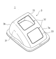
図1は本発明に係る分別用ごみ容器の一例を示す斜視図であり、図2は、ごみ容器の蓋体を示す斜視図である。なお、説明の便宜上、図1中に示すように前後方向および左右方向を規定するが、ごみ容器の正面位置は使用形態に応じて適宜である。 FIG. 1 is a perspective view showing an example of a separation waste container according to the present invention, and FIG. 2 is a perspective view showing a lid of the waste container. For convenience of explanation, the front-rear direction and the left-right direction are defined as shown in FIG. 1, but the front position of the waste container is appropriate depending on the usage pattern.
ごみ容器1は、上部が開口した略有底角筒状の容器本体2と、容器本体2の上部に取り付けられる蓋体3を有する。容器本体2は、図示しないが、内側に、ごみ回収用の内袋が収容されるようになっている。
The
容器本体2の側面上部には、蓋体3を着脱自在に保持するフック部材4が回動可能に設けられている。フック部材4は、容器本体2の前面および後面上部に、対向させて一対設けられている。また、容器本体2は、隅部にアールをもたせた外形状で形成されており、上部開口は、略縦長形状となっている。
A
ここで、ごみ容器1を構成する容器本体2および蓋体3は、ポリプロピレン、ポリエチレン等の適宜の合成樹脂系材料を用いて、インジェクションブロー成形等により形成されている。
Here, the container
ごみ容器1の蓋体3は、容器本体2の上部開口の長辺方向に、片流れ状に形成された傾斜面3aを備えている。図2に示す形態では、傾斜面3aが後方から前方へ傾斜した片流れ状に形成され、この傾斜面3aの背面側は急勾配の傾斜面3bとなっている。蓋体3も容器本体2と同様に隅部にアールを持たせた外形状であり、傾斜面3aもアールを有するように形成されている。また、蓋体3は四周裾部が容器本体2の上部開口縁に覆い被さるように、段部31が形成されており、容器本体2の上部に嵌め合わされる形状を有している。
The
図2に示すように、蓋体3は、傾斜面3aの傾斜流れ方向に複数個の開口孔32が形成されている。例示の形態においては、傾斜面3aに前後方向に並んで2つの開口孔32が配列されており、それぞれ略矩形の同形状に開設されている。これらの開口孔32は、それぞれ投入口部材34a〜34cが装着されて、ごみ容器1のごみの投入口35を形成する(図1参照)。各開口孔32は、周縁部が傾斜面3aの表面方向にリブ33が立上げられている。
As shown in FIG. 2, the
図3は、ごみ容器1における投入口のバリエーションを示す斜視図であり、図4は、投入口部材の例を示す裏面側の斜視図である。
FIG. 3 is a perspective view showing a variation of the inlet in the
蓋体3に装着される投入口部材34a、34b、34cは、ごみの種類ごとに異なる孔形状および色彩で形成されている。すなわち、投入口部材34a〜34cは、略矩形状の縁フレーム341に、異なる形態の投入口35がそれぞれ設けられている。
The
投入口35の形状は複数種類あり、例えば、缶や瓶、ペットボトルなどの投入を許容する円形状の投入口35を有する投入口部材34a(図4(a)参照)、また、可燃ごみあるいは不燃ごみ等の不定形のごみの投入を許容する略矩形状の投入口35を有する投入口部材34bがある。さらに、略矩形状の投入口35に開閉蓋351が取り付けられた開閉蓋付き投入口35を有する投入口部材34c(図4(b)参照)もある。円形状の投入口35は、特にペットボトル用に楕円形状であってもよい。
There are a plurality of shapes of the
これらの複数種類の投入口部材34a〜34cは、ごみ容器1の分別形態に応じて、蓋体3の開口孔32に組み合わせ自在に装着される。例示した図1では、蓋体3の前方の開口孔32に開閉蓋351付きの略矩形状の投入口35が設けられた投入口部材34cが装着されている。また、後方の開口孔32には、円形状の投入口35を備えた投入口部材34aが装着されている。図3(a)では、投入口部材34bと投入口部材34aが、図3(b)では、投入口部材34cと投入口部材34bが、さらに図3(c)では、投入口部材34bと投入口部材34cが、それぞれ組み合わせられて蓋体3に装着されている。
The plurality of types of
また、投入口部材34a〜34cは、投入口35の形状、すなわち投入を許容するごみの種類に応じて、異なる色で形成されていることが好ましい。例えば、缶回収用の投入口35であれば黄色の投入口部材34aとし、瓶回収用の投入口35であれば青色の投入口部材34aとするなど、使用者に回収するごみの種類をわかりやすく示すことが可能である。また、これらの投入口部材34a〜34cの色は、容器本体2および蓋体3の色とも異なることが望ましい。
Further, it is preferable that the
図4に示すように、投入口部材34a、34cは、蓋体3の開口孔32に嵌入する内枠342が裏面側に立設され、この内枠342には、開口孔32に係止する複数の爪部343が突設されている。
As shown in FIG. 4, the
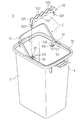
図5は、容器本体2の内側の構造を示す斜視図である。例示するように、容器本体2には、2枚の内袋を保持しうるように袋取付部材5が配設される。袋取付部材5は、前記蓋体3の投入口35の配置に対応させて設けられ、容器本体2に設置される内袋により、容器本体2の内部は前後に区画される。
FIG. 5 is a perspective view showing the inner structure of the
袋取付部材5は、容器本体2の上部開口縁の内側に沿って配設される押さえ枠51、51と、容器本体2の対向する側面間上部に架け渡される仕切材52とを備えている。押さえ枠51、51は、それぞれ容器本体2の長辺方向の側面中央上部の支点21に支着され、容器本体2の上部内周に沿って略コ字状に形成されている。各押さえ枠51、51は、支点21を回動中心として、起伏自在に軸支されている。
The
また、例示の場合、蓋体3において前後に均等配置された投入口35(開口孔34)に対応して、容器本体2の内部が上部開口の長辺方向を二分割するように、仕切材52が配設される。仕切材52は、一体とされた二枚の平行板材521、521に、内袋の端部を係止可能な凸部522が設けられている。例示の場合、凸部522は複数個が均等間隔で設けられて、略波形状を形成している。
Moreover, in the case of illustration, the partition material is formed so that the inside of the container
また、仕切材52は、その両端部が下方へ突出した固定片523となされ、容器本体2の上部開口縁における支点21に固着された固定部53、53に支持されている。各固定部53には、仕切材52の固定片523を嵌入可能な固定孔531が、複数個配設されている。容器本体2の大きさに応じて、固定部53のいずれかの固定孔531を選択して仕切材52の固定片523、523を嵌入させるようにする。これにより、一種類の長さの仕切材52で、異なる容器本体2の内法寸法に対応することができる。
Further, the
このように、容器本体2の上部開口縁に、袋取付部材5を配設することにより、容器本体2内には内袋を容易に設置することができる。すなわち、内袋の端縁部を、押さえ枠51と容器本体2との間に挟み込むとともに、仕切材52の平行板材521、521間に、内袋の残りの端縁部を折り返して挟み込み、複数の凸部522…522で係止させることができる。これにより、容器本体2の内部は、内袋によって二分され、二種類のごみを分別して回収することが可能となる。
Thus, by arranging the
これにより、容器本体2の内部は内袋のみで区画されて、仕切板などで明確に領域を区分されていないので、一方の内袋のごみが多くなっても許容される。すなわち、ごみ容器1は複数枚の内袋を袋取付部材5のみで保持する構成であるので、容器本体2の内部で、内袋はその大きさを自由に拡げることができる。例示のように保持される2枚の内袋は、その間に仕切板等を介在させないので、一方の内袋が投入されたごみでいっぱいになっても、他方の内袋が設置されている方へふくらむことができ、ごみの投入許容量に幅をもたせることができる。これにより、一方の投入口35から投入されるごみの量が他方より多い場合でも、直ちに一方の内袋を交換しなければならないということは避けられ、内袋の交換頻度を少なくして、ごみの回収をすることも可能となる。
Thereby, since the inside of the container
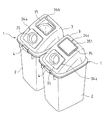
かかるごみ容器1は、単独で設置されるだけでなく、図6に示すように、複数個が隣接配置される利用形態も可能である。そして、蓋体3の投入口35を、複数種類の投入口部材34a〜34cを組み合わせて装着することで、多様なごみの分別形態に対応することができる。この場合、容器本体2は、隣接して並べられた他の容器本体2と、連結部材6により一体に結合される。
Such a
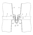
図7は、連結部材6の一例を示す斜視図であり、図8は容器本体2同士の連結部の部分断面図である。この連結部材6は、隣接する容器本体2、2の上部開口縁にそれぞれ嵌着されて挟持する二つの挟持部61、61と、これらの挟持部61、61間に設けられて蓋体3の取付クリアランスを形成する溝部62とを有する形状となっている。溝部62には、連結リブ63が配設され、側面に着脱爪64、64が弾性的に形成されている。着脱爪64は、溝部62の底部から立設され、外方へ突出している。これにより、図8に示されるように、挟持部61で挟み込んだ容器本体2の端縁部を、下方から着脱爪64の屈曲した先端部が係合保持して、連結部材6が容器本体2に固着される。着脱爪64は弾性的に形成されているので、容器本体2との係合解除も容易であり、連結部材6の着脱も適宜行うことができる。固着された連結部材6の溝部62には、隣接するごみ容器1同士の各蓋体3の四周裾部が挿入される。
FIG. 7 is a perspective view showing an example of the connecting
このように構成されるごみ容器1は、図1に示すように前後方向に投入口35が配置されているので、場所をとらず狭い幅スペースにも設置することができる。また、蓋体3の傾斜面3aの流れ方向に複数の投入口35が配列された形態であるため、ごみ容器1が奥行き方向に長くとも、後方の投入口35にもごみを投入しやすく形成することができる。
As shown in FIG. 1, the
さらに、図6に示すように、ごみ容器1を2個並設したり、図示しないが3個以上連結して設置したりする使用形態も可能であり、投入口35の形態の組み合わせにより、省スペースで多様なごみの分別回収を行うことができる。ごみ容器1同士は、連結部材6で結合されているので、がたついたり倒れたりする不都合も生じず、好適に利用することができる。
Furthermore, as shown in FIG. 6, it is possible to use two
なお、容器本体2と蓋体3とは、互いに対をなす一組のごみ容器1として提供されてもよいが、既に使用されている規定容量の容器本体2に対し、適応する大きさの蓋体3を新たに提供して、ごみの分別を促進する利用形態も可能である。また、容器本体2および蓋体3を透明体で形成して、投入されたごみをごみ容器1の外側から視認できるようにすることで、ごみの分別意識が高まり、効果的に分別回収を進めることが可能となる。
The
また、本発明のごみ容器1は、各部材の構成を他の様々な形で実施することができる。そのため、上述の実施形態はあらゆる点で単なる例示にすぎず、限定的なものではない。
Moreover, the
1 ごみ容器
2 容器本体
3 蓋体
3a 傾斜面
31 段部
32 開口孔
33 リブ
34 投入口部材
35 投入口
4 フック部材
5 袋取付部材
51 押さえ枠
52 仕切材
53 固定部
6 連結部材
61 挟持部
62 溝部
DESCRIPTION OF
Claims (7)
前記蓋体は、片流れ状に形成された傾斜面を備え、この傾斜面の傾斜流れ方向に複数個の投入口が配列されており、前記容器本体は、投入口の配置に対応させて複数の内袋を保持しうる袋取付部材が備えられて、これらの内袋により内部が区画されることを特徴とする分別用ごみ容器。 A container main body in which an upper part is opened and an inner bag for collecting garbage is accommodated inside, and a lid body that is provided with a waste inlet and is attached to the upper part of the container main body,
The lid includes an inclined surface formed in a single flow shape, and a plurality of input ports are arranged in the inclined flow direction of the inclined surface, and the container body has a plurality of input ports corresponding to the arrangement of the input ports. A garbage container for separation, comprising a bag attaching member capable of holding an inner bag, and the inside of the bag is partitioned by these inner bags.
前記容器本体は隅部にアールを設けた略直方体形状の外形状に形成されるとともに、上部開口の長辺方向に沿って前記蓋体の傾斜面が設けられて、容器本体の内部が上部開口の長辺方向を分割するように区画されていることを特徴とする分別用ごみ容器。 A waste container for separation according to claim 1,
The container body is formed in a substantially rectangular parallelepiped outer shape with rounded corners, and an inclined surface of the lid body is provided along the long side direction of the upper opening so that the inside of the container body is the upper opening. A waste container for separation, which is partitioned so as to divide the long side direction.
前記蓋体の投入口は、蓋体の傾斜面に形成された互いに同形状の複数個の開口孔に、投入口が開設された着脱自在な投入口部材を装着して設けられることを特徴とする分別用ごみ容器。 A waste container for separation according to claim 1 or 2,
The opening of the lid is provided with a plurality of openings of the same shape formed on the inclined surface of the lid by attaching a detachable inlet member having an opening. Garbage container for sorting.
前記投入口部材は、略円形あるいは楕円形の投入口、略矩形の投入口、または開閉蓋付きの投入口のいずれかが形成されていることを特徴とする分別用ごみ容器。 A waste container for separation according to claim 3,
The waste container according to any one of the preceding claims, wherein the inlet member is formed with either a substantially circular or elliptical inlet, a substantially rectangular inlet, or an inlet with an open / close lid.
前記袋取付部材は、容器本体の上部開口縁の内側に沿って配設される押さえ枠と、容器本体の対向する側面間上部に架け渡される仕切材とを備え、
前記仕切材は、一体とされた平行板材に内袋の端部を係止可能な凸部が設けられて、平行板材間に内袋の端部を折り返して係止させるとともに、前記押さえ枠にて前記内袋を容器本体の上部開口縁の内側に沿って保持することを特徴とする分別用ごみ容器。 A waste container for separation according to any one of claims 1 to 4,
The bag mounting member includes a holding frame disposed along the inner side of the upper opening edge of the container body, and a partition member spanned between the upper portions between the opposing side surfaces of the container body,
The partition member is provided with a convex portion capable of locking the end portion of the inner bag on the integrated parallel plate material, and the end portion of the inner bag is folded and locked between the parallel plate materials, and the holding frame is attached to the holding frame. And holding the inner bag along the inside of the upper opening edge of the container body.
前記仕切材は、その両端部を、容器本体の上部開口縁における対向する内側面にそれぞれ固着される固定部に固定しうる構造を有し、各固定部には、仕切材の端部を嵌入可能な固定孔が複数個配設されていることを特徴とする分別用ごみ容器。 A waste container for separation according to claim 5,
The partition member has a structure capable of fixing both end portions thereof to fixing portions fixed to opposing inner side surfaces of the upper opening edge of the container body, and an end portion of the partition member is inserted into each fixing portion. A garbage container for separation, wherein a plurality of possible fixing holes are provided.
前記容器本体は、さらに、隣接して並べられた他の容器本体と一体に結合可能な連結部材を備え、
この連結部材は、隣接する容器本体の上部開口縁にそれぞれ嵌着されて挟持する二つの挟持部と、これらの挟持部間に設けられて隣接する蓋体の取付クリアランスを形成する溝部とを有することを特徴とする分別用ごみ容器。 A waste container for separation according to any one of claims 1 to 6,
The container body further includes a connecting member that can be integrally coupled to another container body arranged adjacent to the container body,
This connecting member has two clamping parts that are respectively fitted and clamped at the upper opening edges of the adjacent container main bodies, and a groove part that is provided between these clamping parts and forms a mounting clearance for the adjacent lid. A garbage container for separation characterized by this.
Priority Applications (1)
| Application Number | Priority Date | Filing Date | Title |
|---|---|---|---|
| JP2008206149A JP5258032B2 (en) | 2008-08-08 | 2008-08-08 | Garbage container for separation |
Applications Claiming Priority (1)
| Application Number | Priority Date | Filing Date | Title |
|---|---|---|---|
| JP2008206149A JP5258032B2 (en) | 2008-08-08 | 2008-08-08 | Garbage container for separation |
Publications (2)
| Publication Number | Publication Date |
|---|---|
| JP2010042874A true JP2010042874A (en) | 2010-02-25 |
| JP5258032B2 JP5258032B2 (en) | 2013-08-07 |
Family
ID=42014593
Family Applications (1)
| Application Number | Title | Priority Date | Filing Date |
|---|---|---|---|
| JP2008206149A Active JP5258032B2 (en) | 2008-08-08 | 2008-08-08 | Garbage container for separation |
Country Status (1)
| Country | Link |
|---|---|
| JP (1) | JP5258032B2 (en) |
Cited By (7)
| Publication number | Priority date | Publication date | Assignee | Title |
|---|---|---|---|---|
| CN102530449A (en) * | 2010-12-30 | 2012-07-04 | 佛山普立华科技有限公司 | Garbage box |
| CN103350844A (en) * | 2013-08-06 | 2013-10-16 | 徐州市万德福公共设施制造有限公司 | Garbage can with replaceable throwing port |
| EP3056452A1 (en) * | 2015-02-11 | 2016-08-17 | Hailo-Werk Rudolf Loh GmbH & Co. KG | Waste collector |
| JP2019001579A (en) * | 2017-06-13 | 2019-01-10 | サントリーホールディングス株式会社 | Cover for dust bin and dust bin |
| KR102051574B1 (en) * | 2019-06-13 | 2019-12-03 | 홍복선 | Recycling bin of recyclable waste |
| JP2021098571A (en) * | 2019-12-20 | 2021-07-01 | サントリーホールディングス株式会社 | Sorting auxiliary tool and trash box |
| JP7493332B2 (en) | 2019-12-20 | 2024-05-31 | サントリーホールディングス株式会社 | Sorting aids and bins |
Citations (8)
| Publication number | Priority date | Publication date | Assignee | Title |
|---|---|---|---|---|
| US4874111A (en) * | 1989-01-27 | 1989-10-17 | Heller Triangle Spring Co. | Multi-compartment refuse container |
| JPH0820401A (en) * | 1994-03-05 | 1996-01-23 | Arai:Kk | Refuse box with variable partition plate |
| JPH10139105A (en) * | 1996-11-08 | 1998-05-26 | Sekisui Chem Co Ltd | Refuse bin for sorted collection |
| JP2002128201A (en) * | 2000-10-26 | 2002-05-09 | Mizushima Kogyo Kk | Connection device for refuse container |
| JP2004131210A (en) * | 2002-10-08 | 2004-04-30 | Gifu Plast Ind Co Ltd | Sorting collection vessel |
| JP2006206317A (en) * | 2005-01-28 | 2006-08-10 | Naoki Tsuji | Partitioning tool for classification of garbage container |
| JP2006290598A (en) * | 2005-04-14 | 2006-10-26 | Takao Fukuda | Divided type trash can |
| JP2006327751A (en) * | 2005-05-26 | 2006-12-07 | Takao Fukuda | Separate type trash can |
-
2008
- 2008-08-08 JP JP2008206149A patent/JP5258032B2/en active Active
Patent Citations (8)
| Publication number | Priority date | Publication date | Assignee | Title |
|---|---|---|---|---|
| US4874111A (en) * | 1989-01-27 | 1989-10-17 | Heller Triangle Spring Co. | Multi-compartment refuse container |
| JPH0820401A (en) * | 1994-03-05 | 1996-01-23 | Arai:Kk | Refuse box with variable partition plate |
| JPH10139105A (en) * | 1996-11-08 | 1998-05-26 | Sekisui Chem Co Ltd | Refuse bin for sorted collection |
| JP2002128201A (en) * | 2000-10-26 | 2002-05-09 | Mizushima Kogyo Kk | Connection device for refuse container |
| JP2004131210A (en) * | 2002-10-08 | 2004-04-30 | Gifu Plast Ind Co Ltd | Sorting collection vessel |
| JP2006206317A (en) * | 2005-01-28 | 2006-08-10 | Naoki Tsuji | Partitioning tool for classification of garbage container |
| JP2006290598A (en) * | 2005-04-14 | 2006-10-26 | Takao Fukuda | Divided type trash can |
| JP2006327751A (en) * | 2005-05-26 | 2006-12-07 | Takao Fukuda | Separate type trash can |
Cited By (7)
| Publication number | Priority date | Publication date | Assignee | Title |
|---|---|---|---|---|
| CN102530449A (en) * | 2010-12-30 | 2012-07-04 | 佛山普立华科技有限公司 | Garbage box |
| CN103350844A (en) * | 2013-08-06 | 2013-10-16 | 徐州市万德福公共设施制造有限公司 | Garbage can with replaceable throwing port |
| EP3056452A1 (en) * | 2015-02-11 | 2016-08-17 | Hailo-Werk Rudolf Loh GmbH & Co. KG | Waste collector |
| JP2019001579A (en) * | 2017-06-13 | 2019-01-10 | サントリーホールディングス株式会社 | Cover for dust bin and dust bin |
| KR102051574B1 (en) * | 2019-06-13 | 2019-12-03 | 홍복선 | Recycling bin of recyclable waste |
| JP2021098571A (en) * | 2019-12-20 | 2021-07-01 | サントリーホールディングス株式会社 | Sorting auxiliary tool and trash box |
| JP7493332B2 (en) | 2019-12-20 | 2024-05-31 | サントリーホールディングス株式会社 | Sorting aids and bins |
Also Published As
| Publication number | Publication date |
|---|---|
| JP5258032B2 (en) | 2013-08-07 |
Similar Documents
| Publication | Publication Date | Title |
|---|---|---|
| JP5258032B2 (en) | Garbage container for separation | |
| US5246119A (en) | Customized arrangement for presorting recyclable materials | |
| JP2006327751A (en) | Separate type trash can | |
| JP2006290598A (en) | Divided type trash can | |
| KR200334332Y1 (en) | a garbage can | |
| JP2014122116A (en) | Lid for garbage container and garbage container | |
| JP2937875B2 (en) | Trash can | |
| JP3123762U (en) | Garbage can | |
| JP2007084222A (en) | Garbage box bag retainer frame | |
| KR20200089153A (en) | Separate collection box for connected vinyl bags | |
| JP3208398U (en) | Packaging bag assembly | |
| CN210392311U (en) | Classified garbage bag | |
| JP3244460B2 (en) | Sorting trash container | |
| JP2603247Y2 (en) | Sorting pail | |
| JP2995618B2 (en) | Sorting trash container | |
| JP3113473U (en) | Separable storage box | |
| CN211632087U (en) | Take takeaway cutlery box of rubbish classification and storage function | |
| US20230143316A1 (en) | Waste container | |
| JP2002087503A (en) | Sorting refuse housing vessel | |
| CN210557041U (en) | Sealing device and garbage can | |
| JP3554893B2 (en) | A gusseted paper bag that closes and holds the opening without using any other fasteners | |
| KR20080007761A (en) | Trash can | |
| KR200489536Y1 (en) | A trash bin having a connection unit | |
| JP2009120325A (en) | Collection apparatus | |
| KR100378144B1 (en) | Wastebin |
Legal Events
| Date | Code | Title | Description |
|---|---|---|---|
| A625 | Written request for application examination (by other person) |
Free format text: JAPANESE INTERMEDIATE CODE: A625 Effective date: 20110617 |
|
| A977 | Report on retrieval |
Free format text: JAPANESE INTERMEDIATE CODE: A971007 Effective date: 20120920 |
|
| A131 | Notification of reasons for refusal |
Free format text: JAPANESE INTERMEDIATE CODE: A131 Effective date: 20120925 |
|
| A521 | Written amendment |
Free format text: JAPANESE INTERMEDIATE CODE: A523 Effective date: 20121112 |
|
| RD02 | Notification of acceptance of power of attorney |
Free format text: JAPANESE INTERMEDIATE CODE: A7422 Effective date: 20121112 |
|
| TRDD | Decision of grant or rejection written | ||
| A01 | Written decision to grant a patent or to grant a registration (utility model) |
Free format text: JAPANESE INTERMEDIATE CODE: A01 Effective date: 20130326 |
|
| A61 | First payment of annual fees (during grant procedure) |
Free format text: JAPANESE INTERMEDIATE CODE: A61 Effective date: 20130419 |
|
| FPAY | Renewal fee payment (event date is renewal date of database) |
Free format text: PAYMENT UNTIL: 20160502 Year of fee payment: 3 |
|
| R150 | Certificate of patent or registration of utility model |
Ref document number: 5258032 Country of ref document: JP Free format text: JAPANESE INTERMEDIATE CODE: R150 Free format text: JAPANESE INTERMEDIATE CODE: R150 |