JP2010042307A - Humidifying chamber - Google Patents
Humidifying chamber Download PDFInfo
- Publication number
- JP2010042307A JP2010042307A JP2009267835A JP2009267835A JP2010042307A JP 2010042307 A JP2010042307 A JP 2010042307A JP 2009267835 A JP2009267835 A JP 2009267835A JP 2009267835 A JP2009267835 A JP 2009267835A JP 2010042307 A JP2010042307 A JP 2010042307A
- Authority
- JP
- Japan
- Prior art keywords
- chamber
- flow tube
- humidification chamber
- humidification
- gas
- Prior art date
- Legal status (The legal status is an assumption and is not a legal conclusion. Google has not performed a legal analysis and makes no representation as to the accuracy of the status listed.)
- Granted
Links
- XLYOFNOQVPJJNP-UHFFFAOYSA-N water Substances O XLYOFNOQVPJJNP-UHFFFAOYSA-N 0.000 claims abstract description 85
- 239000012530 fluid Substances 0.000 claims abstract description 9
- 238000003780 insertion Methods 0.000 claims description 5
- 230000037431 insertion Effects 0.000 claims description 5
- 238000012546 transfer Methods 0.000 claims description 5
- 238000013022 venting Methods 0.000 claims description 2
- 239000007789 gas Substances 0.000 abstract description 53
- 230000033001 locomotion Effects 0.000 abstract description 16
- 230000008901 benefit Effects 0.000 description 8
- 230000029058 respiratory gaseous exchange Effects 0.000 description 6
- 238000007789 sealing Methods 0.000 description 5
- 230000008020 evaporation Effects 0.000 description 4
- 238000001704 evaporation Methods 0.000 description 4
- 230000000295 complement effect Effects 0.000 description 3
- 230000008878 coupling Effects 0.000 description 3
- 238000010168 coupling process Methods 0.000 description 3
- 238000005859 coupling reaction Methods 0.000 description 3
- 238000001746 injection moulding Methods 0.000 description 3
- 239000007788 liquid Substances 0.000 description 3
- 230000007246 mechanism Effects 0.000 description 3
- 230000000241 respiratory effect Effects 0.000 description 3
- 238000013459 approach Methods 0.000 description 2
- 230000005494 condensation Effects 0.000 description 2
- 238000009833 condensation Methods 0.000 description 2
- 238000004519 manufacturing process Methods 0.000 description 2
- 239000004033 plastic Substances 0.000 description 2
- QVGXLLKOCUKJST-UHFFFAOYSA-N atomic oxygen Chemical compound [O] QVGXLLKOCUKJST-UHFFFAOYSA-N 0.000 description 1
- 230000004888 barrier function Effects 0.000 description 1
- 230000009286 beneficial effect Effects 0.000 description 1
- 230000005540 biological transmission Effects 0.000 description 1
- 238000009530 blood pressure measurement Methods 0.000 description 1
- 238000004140 cleaning Methods 0.000 description 1
- 238000009429 electrical wiring Methods 0.000 description 1
- 238000007667 floating Methods 0.000 description 1
- 238000010438 heat treatment Methods 0.000 description 1
- 238000002347 injection Methods 0.000 description 1
- 239000007924 injection Substances 0.000 description 1
- 230000003993 interaction Effects 0.000 description 1
- 230000013011 mating Effects 0.000 description 1
- 238000005259 measurement Methods 0.000 description 1
- 238000000034 method Methods 0.000 description 1
- 208000001797 obstructive sleep apnea Diseases 0.000 description 1
- 239000001301 oxygen Substances 0.000 description 1
- 229910052760 oxygen Inorganic materials 0.000 description 1
- 238000004023 plastic welding Methods 0.000 description 1
- 210000002345 respiratory system Anatomy 0.000 description 1
- 201000002859 sleep apnea Diseases 0.000 description 1
- 230000001954 sterilising effect Effects 0.000 description 1
- 238000004659 sterilization and disinfection Methods 0.000 description 1
- 239000012815 thermoplastic material Substances 0.000 description 1
- 229920006352 transparent thermoplastic Polymers 0.000 description 1
- 238000009423 ventilation Methods 0.000 description 1
Images


Classifications
-
- A—HUMAN NECESSITIES
- A61—MEDICAL OR VETERINARY SCIENCE; HYGIENE
- A61M—DEVICES FOR INTRODUCING MEDIA INTO, OR ONTO, THE BODY; DEVICES FOR TRANSDUCING BODY MEDIA OR FOR TAKING MEDIA FROM THE BODY; DEVICES FOR PRODUCING OR ENDING SLEEP OR STUPOR
- A61M16/00—Devices for influencing the respiratory system of patients by gas treatment, e.g. mouth-to-mouth respiration; Tracheal tubes
- A61M16/10—Preparation of respiratory gases or vapours
- A61M16/14—Preparation of respiratory gases or vapours by mixing different fluids, one of them being in a liquid phase
- A61M16/16—Devices to humidify the respiration air
-
- A—HUMAN NECESSITIES
- A61—MEDICAL OR VETERINARY SCIENCE; HYGIENE
- A61M—DEVICES FOR INTRODUCING MEDIA INTO, OR ONTO, THE BODY; DEVICES FOR TRANSDUCING BODY MEDIA OR FOR TAKING MEDIA FROM THE BODY; DEVICES FOR PRODUCING OR ENDING SLEEP OR STUPOR
- A61M16/00—Devices for influencing the respiratory system of patients by gas treatment, e.g. mouth-to-mouth respiration; Tracheal tubes
- A61M16/10—Preparation of respiratory gases or vapours
- A61M16/1075—Preparation of respiratory gases or vapours by influencing the temperature
- A61M16/109—Preparation of respiratory gases or vapours by influencing the temperature the humidifying liquid or the beneficial agent
-
- A—HUMAN NECESSITIES
- A61—MEDICAL OR VETERINARY SCIENCE; HYGIENE
- A61M—DEVICES FOR INTRODUCING MEDIA INTO, OR ONTO, THE BODY; DEVICES FOR TRANSDUCING BODY MEDIA OR FOR TAKING MEDIA FROM THE BODY; DEVICES FOR PRODUCING OR ENDING SLEEP OR STUPOR
- A61M16/00—Devices for influencing the respiratory system of patients by gas treatment, e.g. mouth-to-mouth respiration; Tracheal tubes
- A61M16/0057—Pumps therefor
- A61M16/0066—Blowers or centrifugal pumps
Abstract
Description
本発明は、加湿気体を供給するための装置に関する。より詳細には、例えば、消費者用CPAP供給装置におけるような、患者の呼吸補助を行なう一体型装置のための加湿器構成に関する。 The present invention relates to an apparatus for supplying a humidified gas. More particularly, it relates to a humidifier arrangement for an integrated device that provides patient respiratory assistance, such as in a consumer CPAP delivery device.
加湿システムは、ヒータベースと、ヒータベースの上に取り付けられた使い捨て加湿チャンバとを含むものが知られており、チャンバの中で、水の供給をヒータベースにより加熱することができる。空気は、加湿チャンバのルーフの入口空気ポートを通ってチャンバに入り、給水源からの水の蒸発により加湿され、その後、加湿チャンバのルーフの出口ポートを通ってチャンバから出て行く。 Humidification systems are known that include a heater base and a disposable humidification chamber mounted on the heater base, in which the supply of water can be heated by the heater base. The air enters the chamber through the roof inlet air port of the humidification chamber, is humidified by the evaporation of water from the water supply, and then exits the chamber through the outlet port of the humidification chamber.
この種の加湿チャンバは、現在は、例えば、閉塞型睡眠時無呼吸症候群の在宅治療のために意図されたコンパクトな携帯型ベンチレータ(CPAP装置)にも用いられている。加湿器ベースは、スライドオン加湿チャンバと併せて用いるようにされ、装置に対するチャンバの連結は、単一の摺動運動により達成され、入口空気ポートは、チャンバの側部を水平方向に通るように形成される。空気は、入口空気ポートを通って加湿チャンバに入り、加湿空気は、加湿チャンバから出て、加湿チャンバの上部にある出口ポートを通って呼吸導管の中に入る。 This type of humidification chamber is also currently used in compact portable ventilators (CPAP devices) intended for home treatment of, for example, obstructive sleep apnea syndrome. The humidifier base is intended to be used in conjunction with a slide-on humidification chamber, the connection of the chamber to the device is achieved by a single sliding motion, and the inlet air port passes horizontally through the side of the chamber. It is formed. Air enters the humidification chamber through the inlet air port, and the humidified air exits the humidification chamber and enters the breathing conduit through the outlet port at the top of the humidification chamber.
これらの構成の問題点は、補充目的のためにチャンバを取り外す前に、別の動作で患者の呼吸導管を加湿チャンバの上部から外さなくてはならないことである。これらの構成のさらに別の問題点は、加熱された呼吸導管を使用するには、別の電気ワイヤ接続が要求されることである。 The problem with these configurations is that the patient's respiratory conduit must be disconnected from the top of the humidification chamber in a separate operation before the chamber is removed for refill purposes. Yet another problem with these configurations is that separate electrical wire connections are required to use a heated breathing conduit.
本発明を、特にCPAP供給製品を参照して説明する。しかし、本発明は、加圧気体供給源及び加湿モジュールを含む、あらゆるコンパクトな一体型加湿気体供給製品に適用可能であることが解る。例えば、物理的に同様な装置を、患者の換気、加湿酸素の供給、及び加湿吸入に用いることができる。 The present invention will be described with particular reference to CPAP supplied products. However, it will be appreciated that the present invention is applicable to any compact integrated humidified gas supply product, including a pressurized gas supply and a humidification module. For example, physically similar devices can be used for patient ventilation, humidified oxygen supply, and humidified inhalation.
本発明の目的は、少なくとも上述の問題点を克服し、又は少なくとも公衆に対して有益な選択肢を与える加湿気体を供給する装置を提供することである。 It is an object of the present invention to provide an apparatus for supplying a humidified gas that overcomes at least the above-mentioned problems or at least provides a beneficial option to the public.
本発明の第1の態様は、
気体加湿装置とともに用いられ加湿チャンバであって、
底部に開口を有する水チャンバを構成するコンテナと、
前記水チャンバの底部の開口を囲む熱伝導ベースと、
前記コンテナへの略水平な気体入口と、
前記コンテナからの略水平な気体出口と、
前記気体入口と前記気体出口は、平行であり且つ整列し前記加湿チャンバが単一動作で前記加湿気体供給装置と係合されるように構成され、
前記単一動作は、同時に、前記気体出口及び前記気体入口との流体連結を形成および解除することが可能であり、さらに、前記熱伝導ベースを付勢し前記加湿気体供給装置のヒータに隣接または接触させる、
ことを特徴とする加湿チャンバが提供される。
The first aspect of the present invention is:
A humidification chamber used with a gas humidifier,
A container constituting a water chamber having an opening at the bottom;
A heat conducting base surrounding an opening at the bottom of the water chamber;
A substantially horizontal gas inlet to the container;
A substantially horizontal gas outlet from the container;
The gas inlet and the gas outlet are configured to be parallel and aligned so that the humidification chamber engages the humidified gas supply in a single operation;
The single operation can simultaneously form and break fluid connection with the gas outlet and the gas inlet, and further energize the heat transfer base and adjacent to the heater of the humidified gas supply device or Contact,
A humidification chamber is provided.
少なくとも前記単一動作の最終段階が、前記加湿気体供給装置への前記加湿チャンバの好ましい挿入方向に対応し、
前記好ましい挿入方向が、前記チャンバのベースと略平行であるのが好ましい。
At least the final stage of the single operation corresponds to a preferred direction of insertion of the humidification chamber into the humidification gas supply device;
The preferred insertion direction is preferably substantially parallel to the base of the chamber.
前記チャンバは、さらに、
前記気体入口の内側縁部から前記加湿チャンバの中に延びる第1の細長い流管であって、前記流管の遠位端の開口が前記チャンバの壁から離れている第1の細長い流管と、
前記気体出口の内側縁部から前記加湿チャンバの中に延びる第2の細長い流管であって、前記流管の遠位端の開口が前記チャンバの壁から離れている第2の細長い流管と、を備えているのが好ましい。
The chamber further includes
A first elongate flow tube extending into the humidification chamber from an inner edge of the gas inlet, the first elongate flow tube having an opening at the distal end of the flow tube away from the wall of the chamber; ,
A second elongate flow tube extending from the inner edge of the gas outlet into the humidification chamber, the second elongate flow tube having an opening at the distal end of the flow tube away from the chamber wall; Are preferably provided.
前記第1の流管の開口が該第1の流管の軸線を横切る方向に面し、
前記第2の流管の開口が該第2の流管の軸線を横切る方向に面しているのが好ましい。
The opening of the first flow tube faces in a direction transverse to the axis of the first flow tube;
Preferably, the opening of the second flow tube faces in a direction transverse to the axis of the second flow tube.
前記横切る方向が、下方向ではないのが好ましい。
前記横切る方向が、上方向であるのが好ましい。
The transverse direction is preferably not downward.
The transverse direction is preferably an upward direction.
前記チャンバは、前記第1および第2の流管の間にバッフルを有しているのが好ましい。 The chamber preferably has a baffle between the first and second flow tubes.
前記バッフルが、前記チャンバの屋根から延び、前記チャンバが使用時予想最高水位まで注水されたときの前記チャンバ内の水面より下方で終端しているのが好ましい。 Preferably, the baffle extends from the roof of the chamber and terminates below the water level in the chamber when the chamber is filled to the highest water level expected in use.
前記第2の流管が空気抜きオリフィスを備え、
該空気抜きオリフィスは、前記の細長い流管の頂部に配置され、前記気体出口に隣接した前記細長い流管の端に向けて配置されているのが好ましい。
The second flow tube comprises an air vent orifice;
The venting orifice is preferably located at the top of the elongate flow tube and towards the end of the elongate flow tube adjacent to the gas outlet.
前記加湿チャンバの前記気体入口と前記気体出口が、それぞれ、雌ポートであり、
前記加湿チャンバが、ほぼ円筒形であり、
前記雌ポートが、円筒形壁の頂部に隣接する円筒面に対して開いているのが好ましい。
Each of the gas inlet and the gas outlet of the humidification chamber is a female port;
The humidification chamber is substantially cylindrical;
The female port is preferably open to a cylindrical surface adjacent to the top of the cylindrical wall.
本発明に関連する当業者であれば、特許請求の範囲に定義される本発明の範囲から離れることなく、構成に対する多くの変更、及び本発明の広く異なる実施形態及び適用例を思いつくであろう。本明細書における開示及び説明は、純粋に例示的なものであり、どのような意味でも制限することを意図するものではない。 Those skilled in the art to which the present invention pertains will contemplate many changes in configuration and widely different embodiments and applications of the present invention without departing from the scope of the present invention as defined in the claims. . The disclosures and the descriptions herein are purely illustrative and are not intended to be in any sense limiting.
本発明の実施形態を、より詳細に説明する。
図1及び図2を参照すると、CPAPにおける本発明の好ましい実施形態は、ブロワー及びヒータベースを含むハウジングと、対応する水チャンバとを有する。気体入口ポート5及び気体出口ポート6を有する水チャンバが、携帯型CPAP装置と併せて示されている。CPAP装置は、スライドオン加湿チャンバを受け入れるように構成されている。CPAP装置は、連結マニホルドを通して、水チャンバの気体入口/出口ポートに連結する。気体入口及び出口ポートは、単一の摺動運動で、CPAP装置の連結マニホルド8に連結される。連結マニホルド8は、さらに、加湿空気を患者に供給するための可撓性呼吸導管を受け入れるのに適した補助出口連結ポート9を提供している。
The embodiment of the present invention will be described in more detail.
Referring to FIGS. 1 and 2, the preferred embodiment of the present invention in CPAP has a housing containing a blower and a heater base, and a corresponding water chamber. A water chamber having a
CPAP装置は、チャンバ受け入れベイ47において、水チャンバを加熱するヒータベース58を含む。水チャンバをCPAP装置に配置し係合するための固定装置が設けられている。固定装置は、チャンバ受け入れベイ47の周辺部に、固定ラッチ19及びスロット17を有する。スロットは、水チャンバのベースの周りにあるフランジ18と協働して、使用中に、チャンバを固定する。固定ラッチ19は、チャンバが係合されると、これが取り外されるのを阻止するように作動する。固定手段及び連結マニホルドは、平行な作動軸で配置されて、連結マニホルド8に対するチャンバ入口ポート5及びチャンバ出口ポート6の連結が、同じ単一のスライドオン運動で、チャンバをCPAP装置の中に固定することと併せて達成されるようにする。ポート5、6に対するコネクタの挿入方向は、少なくとも、スライドオン運動の終端部分と同じである。
The CPAP apparatus includes a
ロック位置及び解除位置を有するラッチ19は、ロック位置の方向に付勢されて、チャンバがCPAP装置から取り外されるのを阻止する。ラッチの正面は、水チャンバをCPAP装置に取り付けるのに採用される単一のスライドオン運動中に、フランジ18が、固定ラッチ19を解除位置に付勢して、水チャンバが適切に取り付けられるのを可能にするような形状にすることができる。水チャンバのベースが適切にヒータベースに配置され、入口5及び出口6が適切に連結マニホルド8と係合されると、フランジ18及びチャンバのベースは、固定ラッチ19と接触しなくなる。これにより、図2に示されるように、固定ラッチの付勢手段がラッチをロック位置に付勢して、水チャンバが取り外されるのを阻止する。
A
連結マニホルド8は、加圧空気流をブロワーから受け、これを水チャンバ2の中に向ける通路と、水チャンバの出口ポート6により受けた空気流をCPAP患者用出口ポート9に向ける通路とを含むことが好ましい。マニホルド入口ポート7をマニホルド患者用出口ポート9まで連結する連結通路は、図1においては隠れた詳細48で示されている。本発明の連結マニホルド8は、取り外し可能な部品で具現されて、気体通路の清掃及び/又は殺菌を助けることが好ましい。1つの好ましい実施形態においては、上述の連結通路は、図1及び図2に示されるように、連結マニホルド8より内側にある。
The connecting manifold 8 includes a passage that receives a pressurized air flow from the blower and directs it into the
使用中、CPAP装置のブロワーからの気体は、出口ポート4を通って出て行き、入口ポート5を通ってチャンバ2に入る。チャンバの加熱手段58は、液体の水をチャンバ内で気化させ、チャンバに入る空気は、チャンバの底部における水源からの水の蒸発により加湿された後に、患者用出口ポート6を通ってチャンバから出て行く。出口ポート6からの加湿空気は、入口ポート7を介して、CPAP装置の連結マニホルド8の中に受け入れられる。連結マニホルド8は、空気を、患者への供給のために可撓性導管コネクタに連結するようにされた出口ポート9に向ける。CPAP装置の本体に配置され、水チャンバの上部には直接連結されていない呼吸導管連結部9から得られる利点は、水チャンバをCPAPシステム(呼吸導管を含む)に完全に連結させるか、又はこれらを外すことが、単一のスライドオン又はスライドオフ運動のそれぞれにより達成できることである。この特徴は、従来技術の装置と比較した場合に、補充のための水チャンバの取り外しを単純化する。
In use, gas from the CPAP device blower exits through
例えば、加熱された供給導管において、付加的な電気又は流体連結が要求される場合には、さらに別の利点が得られる。加熱導管の使用は、通常は、導管と加湿空気源との間に電気配線コネクタを要求するが、付加的な流体連結部は、圧力のフィードバック又は測定に用いることができる。本発明においては、コネクタは、導管に対して、あらゆる付加的な電気及び/又は流体連結部54を含むことができる。コネクタは、CPAP機械の連結マニホルド8と一体であり、したがって、使い捨て可能な水チャンバを、例えば、電気伝達接続のない単純なもののままにすることを可能にする。
For example, additional benefits are obtained when additional electrical or fluid connections are required in a heated supply conduit. The use of heated conduits usually requires an electrical wiring connector between the conduit and the humidified air source, but additional fluid connections can be used for pressure feedback or measurement. In the present invention, the connector can include any additional electrical and / or
ここで、本発明の多数の代替的な変形態様を想定し説明する。例えば、マニホルドの加湿気体部分を、ハウジングから別々に取り外すことができるような、加湿気体を水チャンバから可撓性呼吸導管により患者まで供給する、本発明のさらに別の実施形態を想定する。この代替的な実施形態は、図3に示される。入口端部及び出口端部を有するエルボー管は、加湿気体を水チャンバから受け取り、この加湿気体を可撓性呼吸導管の中に向けて、患者に供給するように形成される。この代替的な実施形態においては、CPAP装置ハウジングには、エルボー管を受け取りかつ固定する凹部52が設けられる。凹部52は、ネック部又はくびれをエルボー51の上方に含むことができ、(エルボー51が適切な位置にある場合には)通常の使用の下で、エルボーを適切な位置に保持し、さらに、必要に応じて、エルボーを取り外すことも可能にする。取り外し可能にエルボー51を固定する他の方法は、当業者であれば容易に思いつくであろうことが理解されるであろう。例えば、エルボー51の一方又は他方にあるか、凹部8の周りにあるか、又はこれらの両方にある種々の突起及び相互作用スロットによるものがある。適切な位置に固定された場合には、エルボー管51の入口53は、同じスライドオン運動で、水チャンバの出口8に対する流体連結がなされるように位置決めされる。この代替的な実施形態においては、出口エルボーは、前述のように連結マニホルドの内部分ではなく、呼吸管の終端部分とすることができる。この代替的な実施形態の利点は、潜在的な凝縮と接触する部分が、清掃及び/又は殺菌のために取り外し可能であることである。本実施形態は、さらに、単一のスライドオン/オフ運動で係合可能/係合解除可能という水チャンバの利点を維持する。本実施形態は、さらに、CPAP装置と導管コネクタとの間の付加的な電気又は流体連結54が、直接ハウジングに対して形成されることを可能にして、この代替的手法が、前述の実施形態の利点を維持することを可能にする。
A number of alternative variants of the invention will now be assumed and described. For example, still another embodiment of the invention is envisioned in which humidified gas is supplied from the water chamber to the patient via a flexible breathing conduit such that the humidified gas portion of the manifold can be removed separately from the housing. This alternative embodiment is shown in FIG. An elbow tube having an inlet end and an outlet end is configured to receive humidified gas from the water chamber and direct the humidified gas into the flexible respiratory conduit to the patient. In this alternative embodiment, the CPAP device housing is provided with a
本発明の代替的な実施形態では、水チャンバ及びヒータベースが部分的に又は完全にハウジングの中に囲まれることが想定される。ハウジングは、少なくとも1つの気体入口と、これに隣接し位置合わせされた少なくとも1つの気体出口連結ポートで構成された連結マニホルドを含み、これらは、使用中に、気体を水チャンバに移送及び/又は水チャンバから移送する。第2のハウジングには、連結マニホルドとの整合のために、相補的な入口及び出口連結部が形成されている。この第2のハウジングは、第1のハウジングと係合するようになっており、すべての必要な気体及び電気又は流体連結部を同じスライドオン運動にし、好ましくは、2つのハウジングを互いにロックする固定装置を含む。第2のハウジングは、一体的な空気ブロワーと、CPAPの実施形態の場合においては、患者導管出口ポートとを含むことができる。第1の導管ポートは、使用中に、空気を供給源から受け取り、第2の導管ポートは、加湿空気を患者に供給する。上述の実施形態は、すべての必要な可撓性導管連結部が第2のハウジング(気体供給源を含む)上に製造されるという利点を有する。このことは、水チャンバ及び/又は囲いハウジングが同じスライドオフ/オン運動で取り外され/係合されることを可能にして、チャンバの係合/係合解除及び補充をより単純にする。 In alternative embodiments of the present invention, it is envisioned that the water chamber and heater base are partially or fully enclosed within the housing. The housing includes a connection manifold configured with at least one gas inlet and at least one gas outlet connection port aligned adjacent thereto, which transfers and / or transfers gas to the water chamber during use. Transfer from water chamber. Complementary inlet and outlet connections are formed in the second housing for alignment with the connection manifold. This second housing is adapted to engage with the first housing so that all necessary gas and electrical or fluid connections are in the same slide-on motion, preferably locking the two housings together. Including equipment. The second housing can include an integral air blower and, in the case of CPAP embodiments, a patient conduit outlet port. The first conduit port receives air from the source during use, and the second conduit port supplies humidified air to the patient. The above-described embodiment has the advantage that all the necessary flexible conduit connections are manufactured on the second housing (including the gas source). This allows the water chamber and / or enclosure housing to be removed / engaged with the same slide-off / on motion, making chamber engagement / disengagement and refilling simpler.
本発明の好ましい実施形態においては、加湿器装置と水チャンバとの間を連結するために管状突起(4、7)が形成され、気体をチャンバに供給し、加湿気体をチャンバから受け取る。管状突起は、さらに、弾性ブーツを含み、水チャンバと突起との間に改善されたシールを与えることが好ましい。 In a preferred embodiment of the present invention, tubular protrusions (4, 7) are formed to connect between the humidifier device and the water chamber, supplying gas to the chamber and receiving humidified gas from the chamber. The tubular protrusion further includes an elastic boot, preferably providing an improved seal between the water chamber and the protrusion.
装置のマニホルドと水チャンバとの間の連結が並列ではなく、一方が他方の中に設けられる、例えば、入口と出口とが同軸とすることができる本発明のさらに別の実施形態が想定される。このような構成は、本発明の好ましい実施形態において、より詳細に述べられた構成と同じ利点をもつ。さらに、このような連結部は、圧力測定又は圧力フィードバック並びに電気接続を与えるための同様に構成された管も含むことができる。 Still further embodiments of the invention are envisaged in which the connection between the manifold of the device and the water chamber is not in parallel, one being provided in the other, for example the inlet and outlet can be coaxial. . Such an arrangement has the same advantages as the arrangement described in more detail in the preferred embodiment of the invention. In addition, such connections can also include similarly configured tubes for providing pressure measurement or pressure feedback as well as electrical connections.
上述の好ましい実施形態は、水チャンバが、装置のマニホルドの対応する雄コネクタと嵌合する2つの雌コネクタを有する雄/雌形式の相補的なコネクタを説明したが、当業者であれば、本発明の思想から離れることなく、多くの変形を思いつくであろう。例えば、水チャンバには2つの雄コネクタを形成し、装置のマニホルドには対応する雌コネクタを形成することができ、又は、水チャンバに1つの雄コネクタ及び雌コネクタを形成して、装置のマニホルドの対応する雄コネクタ及び雌コネクタに連結することができる。さらに、水チャンバと装置のマニホルドとを連結するために、雄雌両方の性質をもつコネクタを形成することを想定でき、この場合には、各々のコネクタは、雄形式の突起部分及び雌形式の凹部分の両方を含むことができる。このような連結部は、入口及び出口が、一方が他方の中にある状態で形成された場合に、特に有利である。 While the preferred embodiment described above has described a male / female type complementary connector in which the water chamber has two female connectors that mate with corresponding male connectors on the manifold of the device, those skilled in the art will Many variations will come to mind without departing from the idea of the invention. For example, the water chamber can be formed with two male connectors and the device manifold can be formed with a corresponding female connector, or the water chamber can be formed with one male connector and a female connector to form a device manifold. To corresponding male and female connectors. Furthermore, it is possible to envisage forming male and female connectors to connect the water chamber and the manifold of the device, in which case each connector has a male projection and a female connector. Both recesses can be included. Such a connection is particularly advantageous when the inlet and outlet are formed with one in the other.
本発明の上述の実施形態を参照して、上述の実施形態と併せて用いるのに適した水チャンバの幾つかの共通の特徴を、ここでさらに詳細に説明する。 With reference to the above-described embodiments of the present invention, some common features of a water chamber suitable for use in conjunction with the above-described embodiments will now be described in further detail.
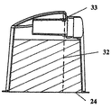
図4及び図5に示されるチャンバは、熱伝導性ベース24により囲まれた、底部開口プラスチックコンテナから構成されており、水平方向に配置された気体入口27及び平行な気体出口28を含む。水チャンバを取り付けるのに採用されるスライドオン方向が水平方向ではなく、水平面又は垂直面から或る角度である、本発明の他の構成も可能であることが想定される。このような場合においては、気体入口27及び出口28は、意図されるスライドオン運動方向と平行でかつこれと位置合わせされて、チャンバの入口/出口ポートと連結マニホルドとの嵌合を可能にすることが好ましい。
The chamber shown in FIGS. 4 and 5 is composed of a bottom open plastic container surrounded by a thermally
本発明の水チャンバは、入口延長管30及び/又は出口延長管31である少なくとも1つの流管を含むことが好ましく、これは、チャンバ壁の周辺部からチャンバの内部の中に内向きに延び、全体的に先細になる本体を有することが好ましい。入口延長管30及び出口延長管31は、チャンバシェル26と同じ透明な熱可塑性材料から成形されることが好ましい。入口/出口延長管を含むことは、チャンバの周りの空気流により生成される雑音を大幅に減少させることが見出された。しかし、流速が高い場合には、水の液滴又は飛び散りが空気流に同伴し、チャンバの出口28に運ばれる可能性がある。このことは、水チャンバが大量の液体を含み、水面がチャンバの出口に近い場合に、特に可能性が高い。この状況は、CPAP装置の出口ポートが患者の供給導管から外れた場合に、回路抵抗を低下させて、著しく高い流速をもたらすことになるように、さらに問題となる可能性がある。さらに、供給導管が連結されていなければ、気体流に同伴するあらゆる液体は、チャンバから直接排出されることになる。この困難性は、種々の延長管構成を含むチャンバにおいては、或る程度緩和することができる。
The water chamber of the present invention preferably includes at least one flow tube that is an
少なくとも1つの延長管は、チャンバが上げ起こされた状態で、チャンバの補充を助ける空気抜き孔33を有することが好ましい。空気抜きは、延長管の上面に配置されることが好ましく、チャンバ壁に連結された延長管の端部の方向に向けられていることが好ましい。図5を参照すると、好ましくは、空気抜き孔33は、タンクが補充のために上げ起こされた場合に、空気抜き弁の高さが、水チャンバに好ましい補充高さ32に対応するように位置決めされる。この特徴は、水チャンバが溢れるのを阻止することを助ける。
The at least one extension tube preferably has an
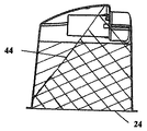
さらに、図6を参照すると、延長管30、31は、水レベル線44により示されるチャンバの傾斜により、気体入口及び気体出口を通って、水が逆流しないようにする堰として作用するのがよい。このことは、チャンバの傾斜により生じる、入口ポート27を通る水の逆流を減少させる。存在するのであれば、空気抜き孔33は、出口延長管31にのみ存在し、入口延長管30には存在しないことが好ましい。或いは、空気抜き孔は、両方に含むことができる。
Further, referring to FIG. 6, the
図10を参照すると、本発明は、さらに、入口延長管と出口延長管との間に配置された下方に延びる中央バッフル又はリブ57を含み、気体が、入口延長管の出口から出口延長管の入口に直接流れることによってチャンバが短絡されるのを防ぐことを確実にしてもよい。バッフルが存在することにより、気体は、より曲がりくねった経路を辿るようにされて、チャンバを通るその移動中に十分な加湿を確実にするが、チャンバ内の圧力損失を受け入れられないレベルにまで増加させることはない。バッフルは、チャンバのルーフから下方に延び、入口/出口ポートの反対側のチャンバ壁の部分から内方に延びることが好ましい。バッフルの大きさは、気体流がチャンバを通る、曲がりくねった経路を辿ることを確実にするだけでなく、さらに、出口延長管31の入口55に入る飛び散りに対して付加的な障壁も与えるものであることが好ましい。飛び散りが延長管に入る危険は、水位が最高のときに最高であるため、バッフルは、チャンバが満たされたときに、水ラインの下で終端するように下方に延びる。
Referring to FIG. 10, the present invention further includes a downwardly extending central baffle or
図4を参照すると、使用中、空気は、入口ポート27によりチャンバの中に受け取られて、入口延長管30内を移動する。入口延長管30を出ると、空気は、チャンバに入り、ここで、給水源からの水の蒸発により加湿される。加湿空気は、矢印45により示されるように、チャンバから出口延長管31を通って流れて、出口ポート28を通って出て行く。図10を参照すると、延長管の代替的な構成があり、ここでは、気体入口27及び気体出口28のそれぞれから最も遠い延長管の遠位端が、延長管の軸から離れる方向に向けられている。延長管は、チャンバ効率を改善するために、チャンバを通って流れる気体の内圧損失を最小にするように成形される。使用中、空気は、入口ポート27によりチャンバの中に受けられて、入口延長管30内を移動する。入口延長管30の上方に面する出口54を出て行く際、気体流は、チャンバ内の水面から離れる方向に向けられて、飛び散り又は水の浮遊が生じる可能性を最小にする。気体流がチャンバに入ると、これは、チャンバのルーフから偏向されて、給水源からの水の蒸発により加湿される。加湿空気は、チャンバから、出口延長管31の上方に面する入口55を通って流れ、出口ポート28を通って出て行く。出口延長管31の上方に向けられた入口55は、飛び散りが水面から出口ポートに対して生じることがある直接経路を排除する。排水穴56が延長管の底部に形成されて、補充後に、水がチャンバの中に戻るように排水されるのを可能にするか、又は、使用中に、凝縮又は飛び散りを蓄積して排水させるのを可能にする。延長管の形状及び方位及び排水穴の位置は、排水穴が低い点にあり、流体が排水穴の方向に流れ、チャンバの中に戻るようなものであることが好ましい。
Referring to FIG. 4, during use, air is received into the chamber by the
或いは、入口延長管の出口及び/又は出口延長管の入口が面する方向は、異なる結果を達成するために変更できることが想定される。例えば、延長管の遠位端における開口部を、延長管の軸の周りで回転させて、あらゆる方向に面するようにすることができる。さらに、入口流管及び出口流管の開口部が面する方向は、同じでなくてもよい。このような構成(例えば、互いに離れる方向に面している)は、飛び散りの可能性を減少させるため、及びバッフルが存在する場合に、飛び散りが延長管の開口部に入る可能性を減少させるのに特に適しているとすることができる。前述の説明は、平行で隣接する円形の入口/出口ポートを有する好ましい実施形態の詳細を与えるが、本発明の精神から離れることなく、他の構成も可能であることが想定される。例えば、チャンバ及び連結マニホルドの入口/出口ポートは、非円形の断面であってもよく、非対称であってもよい。さらに、出口に対する入口ポートの位置を、多数の代替的な構成にすることが可能である。例えば、ポート及び3つの対応する連結部は、さらに、一方が他方の中にある状態で、同軸であってもよいし、オフセットされていてもよい。 Alternatively, it is envisioned that the outlet extension tube outlet and / or the direction in which the outlet extension tube inlet faces can be varied to achieve different results. For example, the opening at the distal end of the extension tube can be rotated about the axis of the extension tube to face in any direction. Further, the direction in which the openings of the inlet flow tube and the outlet flow tube face may not be the same. Such a configuration (eg facing away from each other) reduces the likelihood of splatter and, if a baffle is present, reduces the likelihood of splatter entering the extension tube opening. May be particularly suitable. While the foregoing description gives details of a preferred embodiment having parallel and adjacent circular inlet / outlet ports, it is envisioned that other configurations are possible without departing from the spirit of the invention. For example, the inlet / outlet ports of the chamber and connection manifold may be non-circular in cross section or asymmetric. In addition, the location of the inlet port relative to the outlet can be many alternative configurations. For example, the ports and the three corresponding connections may be coaxial or offset with one in the other.
図7ないし図9を参照すると、組み立てを容易にするために、入口延長管及び出口延長管は、これらのそれぞれの水チャンバの入口又は出口に対するスナップ嵌めとして設けられて、十分な力を適用することにより、入口及び出口を通してチャンバの中に押し付けられて、実質的に防水性で固定した状態にスナップできるようになっている。 Referring to FIGS. 7-9, for ease of assembly, the inlet and outlet extension tubes are provided as snap fits to the inlets or outlets of their respective water chambers to apply sufficient force. This allows it to be pushed through the inlet and outlet into the chamber and snapped into a substantially waterproof and fixed state.
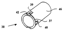
この目的のために、水チャンバの入口27及び出口28ポートの内側端には、内方に垂直に延びる環状フランジ36が形成されており、入口/出口延長管38は、全体的に先細になる管状本体46の一端から垂直に外方に延びる同様なフランジ37を含むことができる。フランジは、取り付けられ組み立てられた状態で、シーリングフランジとして互いに作用する。組み立てられた状態で、延長管を並進運動及び回転運動の両方に対して保持するためには、幾つかの固定機構を設けることができる。各々の場合において、固定機構を、(チャンバの)入口/出口においてであるか、又は入口/出口延長管において形成することができる。しかし、両方の部品は、射出成形が意図されており、チャンバの入口/出口の内面における特定の突起の射出成形は、延長管の外面におけるものの場合よりかなり困難であるため、これらは、延長管上にあることが好ましい。管を並進運動に対して固定し、かつシーリングフランジ間のシーリング状態に固定するためには、入口/出口フランジ36と協働する、延長管の管状本体の周囲に間隔もって配設された複数の保持クリップの突起39を形成することができる。特に、製造を容易にするために、及び単純な2部品射出成形を確実にするために、ノッチ42を、延長管38のフランジ37の突起39に隣接して形成することができる。
For this purpose, the inner ends of the
延長管が或る位置にスナップ嵌めされた場合に、回転運動に対してこれを保持するためには、管状本体の外面に、外方に垂直に延びるフランジ37に隣接しこれと連続する、1つ又はそれ以上の位置決め突起40を周方向に分布させることができる。位置決め突起40は、周方向及び軸方向の両方に、全体的に先細になっていることが好ましい。相補的なノッチ41がチャンバの入口及び出口の内方に延びるフランジ36に形成される。延長管38を取り付ける際、突起40はノッチ41と位置合わせされ、管が完全に挿入されたときには、突起40はノッチ41との緊密な摩擦嵌め状態に入り、完全ではないとしても実質的なシーリングを確実にする。水チャンバの中への延長管の適切な位置及びシーリングを確実にするために採用される機構は、多くの形態をとることができることが理解される。当業者であれば、接着された接合部、種々の形態のプラスチック溶接、及び種々の構成のクリッピング手段及び突起のような多くの代替的手法を思いつくであろう。上述の説明は、1つの特定の好ましい実施形態であり、どのような方法によっても制限することを意味するものではない。
If the extension tube is snapped into place, to retain it against rotational movement, the outer surface of the tubular body is adjacent to and continues to a
述べられた水チャンバの構成は、製造が単純であり、プラスチック部品の各々はこれ自体が単純に射出成形できるものであることが容易に理解されるであろう。したがって、本発明による水チャンバは、顕著な利点を与えるが、既存のチャンバと比較して顕著に高価なものではない。 It will be readily appreciated that the water chamber configuration described is simple to manufacture and that each of the plastic parts can itself be simply injection molded. Thus, while the water chamber according to the present invention provides significant advantages, it is not significantly more expensive than existing chambers.
Claims (10)
底部に開口を有する水チャンバを構成するコンテナと、
前記水チャンバの底部の開口を囲む熱伝導ベースと、
前記コンテナへの略水平な気体入口と、
前記コンテナからの略水平な気体出口と、
前記気体入口と前記気体出口は、平行であり且つ整列し前記加湿チャンバが単一動作で前記加湿気体供給装置と係合されるように構成され、
前記単一動作は、同時に、前記気体出口及び前記気体入口との流体連結を形成および解除することが可能であり、さらに、前記熱伝導ベースを付勢し前記加湿気体供給装置のヒータに隣接または接触させる、
ことを特徴とする加湿チャンバ。 A humidification chamber used with a gas humidifier,
A container constituting a water chamber having an opening at the bottom;
A heat conducting base surrounding an opening at the bottom of the water chamber;
A substantially horizontal gas inlet to the container;
A substantially horizontal gas outlet from the container;
The gas inlet and the gas outlet are parallel and aligned so that the humidification chamber is engaged with the humidification gas supply in a single operation;
The single operation can simultaneously form and break fluid connection with the gas outlet and the gas inlet, and further energize the heat transfer base and adjacent to the heater of the humidified gas supply device or Contact,
A humidification chamber characterized by that.
前記好ましい挿入方向が、前記チャンバのベースと略平行である、
請求項1に記載の加湿チャンバ。 At least the final stage of the single operation corresponds to a preferred direction of insertion of the humidification chamber into the humidification gas supply device;
The preferred insertion direction is substantially parallel to the base of the chamber;
The humidification chamber according to claim 1.
前記気体出口の内側縁部から前記加湿チャンバの中に延びる第2の細長い流管であって、前記流管の遠位端の開口が前記チャンバの壁から離れている第2の細長い流管と、を備えている、
請求項2に記載の加湿チャンバ。 A first elongate flow tube extending into the humidification chamber from an inner edge of the gas inlet, the first elongate flow tube having an opening at the distal end of the flow tube away from the wall of the chamber; ,
A second elongate flow tube extending from the inner edge of the gas outlet into the humidification chamber, the second elongate flow tube having an opening at the distal end of the flow tube away from the chamber wall; Has
The humidification chamber according to claim 2.
前記第2の流管の開口が該第2の流管の軸線を横切る方向に面している、
請求項3に記載の加湿チャンバ。 The opening of the first flow tube faces in a direction transverse to the axis of the first flow tube;
The opening of the second flow tube faces in a direction transverse to the axis of the second flow tube;
The humidification chamber according to claim 3.
請求項4に記載の加湿チャンバ。 The transverse direction is not downward,
The humidification chamber according to claim 4.
請求項4に記載の加湿チャンバ。 The transverse direction is an upward direction,
The humidification chamber according to claim 4.
請求項3ないし6のいずれか1項に記載の加湿チャンバ。 The chamber has a baffle between the first and second flow tubes;
The humidification chamber according to any one of claims 3 to 6.
請求項7に記載の加湿チャンバ。 The baffle extends from the roof of the chamber and terminates below the water level in the chamber when the chamber is filled to the highest water level expected in use.
The humidification chamber according to claim 7.
該空気抜きオリフィスは、前記の細長い流管の頂部に配置され、前記気体出口に隣接した前記細長い流管の端に向けて配置されている、
請求項3ないし8のいずれか1項に記載の加湿チャンバ。 The second flow tube comprises an air vent orifice;
The venting orifice is located at the top of the elongate flow tube and is directed toward the end of the elongate flow tube adjacent to the gas outlet.
The humidification chamber according to any one of claims 3 to 8.
前記加湿チャンバが、ほぼ円筒形であり、
前記雌ポートが、円筒形壁の頂部に隣接する円筒面に対して開いている、
請求項6から請求項9のいずれか1項に記載の加湿チャンバ。 Each of the gas inlet and the gas outlet of the humidification chamber is a female port;
The humidification chamber is substantially cylindrical;
The female port is open to a cylindrical surface adjacent the top of the cylindrical wall;
The humidification chamber according to any one of claims 6 to 9.
Applications Claiming Priority (4)
| Application Number | Priority Date | Filing Date | Title |
|---|---|---|---|
| NZ521446 | 2002-09-17 | ||
| NZ52144602 | 2002-09-17 | ||
| NZ52773403 | 2003-08-20 | ||
| NZ527734 | 2003-08-20 |
Related Parent Applications (1)
| Application Number | Title | Priority Date | Filing Date |
|---|---|---|---|
| JP2004538072A Division JP4436758B2 (en) | 2002-09-17 | 2003-09-17 | Device for supplying humidified gas |
Publications (2)
| Publication Number | Publication Date |
|---|---|
| JP2010042307A true JP2010042307A (en) | 2010-02-25 |
| JP5027205B2 JP5027205B2 (en) | 2012-09-19 |
Family
ID=32033027
Family Applications (2)
| Application Number | Title | Priority Date | Filing Date |
|---|---|---|---|
| JP2004538072A Expired - Lifetime JP4436758B2 (en) | 2002-09-17 | 2003-09-17 | Device for supplying humidified gas |
| JP2009267835A Expired - Lifetime JP5027205B2 (en) | 2002-09-17 | 2009-11-25 | Humidification chamber |
Family Applications Before (1)
| Application Number | Title | Priority Date | Filing Date |
|---|---|---|---|
| JP2004538072A Expired - Lifetime JP4436758B2 (en) | 2002-09-17 | 2003-09-17 | Device for supplying humidified gas |
Country Status (8)
| Country | Link |
|---|---|
| US (1) | US20070079826A1 (en) |
| EP (3) | EP3639879B1 (en) |
| JP (2) | JP4436758B2 (en) |
| AU (2) | AU2003265025B2 (en) |
| CA (5) | CA3067401C (en) |
| DE (1) | DE19212475T1 (en) |
| ES (1) | ES2864689T3 (en) |
| WO (1) | WO2004026382A1 (en) |
Cited By (3)
| Publication number | Priority date | Publication date | Assignee | Title |
|---|---|---|---|---|
| JP2013543753A (en) * | 2010-11-15 | 2013-12-09 | グリュントラー ゲーエムベーハー | Method and apparatus in the field of treatment using medical gas |
| TWI648074B (en) * | 2016-03-01 | 2019-01-21 | 大契連股份有限公司 | Wet high concentration hydrogen mixed gas respiratory system |
| JP2019088809A (en) * | 2012-08-08 | 2019-06-13 | フィッシャー アンド ペイケル ヘルスケア リミテッド | Breathing tube assemblies with adjustable elbow |
Families Citing this family (51)
| Publication number | Priority date | Publication date | Assignee | Title |
|---|---|---|---|---|
| DE10139881B4 (en) * | 2001-08-20 | 2017-06-08 | Resmed R&D Germany Gmbh | Apparatus for supplying a breathing gas and method for controlling the same |
| WO2005011785A1 (en) * | 2003-08-01 | 2005-02-10 | Fisher & Paykel Healthcare Limited | Device for supplying a respiratory gas with integrated humidifier |
| US7607437B2 (en) * | 2003-08-04 | 2009-10-27 | Cardinal Health 203, Inc. | Compressor control system and method for a portable ventilator |
| US8118024B2 (en) | 2003-08-04 | 2012-02-21 | Carefusion 203, Inc. | Mechanical ventilation system utilizing bias valve |
| BRPI0413275A (en) * | 2003-08-04 | 2006-10-10 | Pulmonetic Systems Inc | portable fan and portable fan system |
| US7527053B2 (en) * | 2003-08-04 | 2009-05-05 | Cardinal Health 203, Inc. | Method and apparatus for attenuating compressor noise |
| US8156937B2 (en) * | 2003-08-04 | 2012-04-17 | Carefusion 203, Inc. | Portable ventilator system |
| US7413173B2 (en) * | 2004-09-10 | 2008-08-19 | Ric Investments, Llc | Molded water chamber base plate for use in a humidifier and ventilator assembly |
| DE102006034028A1 (en) | 2005-08-01 | 2007-02-08 | Weinmann Geräte für Medizin GmbH + Co. KG | Artificial respiration e.g. CPAP respiration, apparatus for use in clinic, has respired air humidifier comprising upper part not separable from lower part, and air outlet disposed at preset angle with respect to air inlet |
| WO2007019628A1 (en) | 2005-08-15 | 2007-02-22 | Resmed Ltd | Low cost cpap flow generator and humidifier assembly |
| WO2007019627A1 (en) | 2005-08-15 | 2007-02-22 | Resmed Ltd | Compliant coupling or adaptor |
| CN102133447B (en) * | 2005-08-15 | 2015-01-07 | 瑞思迈有限公司 | Humidifier and/or flow generator for CPAP device |
| US7677246B2 (en) | 2005-09-23 | 2010-03-16 | Ric Investments, Llc | Modular pressure support system |
| CA2625534C (en) * | 2005-10-21 | 2010-02-23 | Compumedics Limited | Apparatus for delivery of pressurised gas |
| AU2006325613B2 (en) | 2005-12-15 | 2012-01-19 | Fisher & Paykel Healthcare Limited | Breathing assistance apparatus |
| CA2959267C (en) | 2006-11-06 | 2020-06-23 | Fisher & Paykel Healthcare Limited | Integrated humidifier chamber and lid |
| EP2152344A1 (en) * | 2007-06-04 | 2010-02-17 | Compumedics Medical Innovation Pty Ltd | Water reservoir baffle |
| CN101690385B (en) | 2007-06-05 | 2015-05-27 | 瑞思迈有限公司 | Electrical heater with particular application to humification and fluid warming |
| USD798437S1 (en) | 2007-07-30 | 2017-09-26 | Fisher & Paykel Healthcare Limited | Breathing apparatus |
| US7997885B2 (en) * | 2007-12-03 | 2011-08-16 | Carefusion 303, Inc. | Roots-type blower reduced acoustic signature method and apparatus |
| US9802022B2 (en) * | 2008-03-06 | 2017-10-31 | Resmed Limited | Humidification of respiratory gases |
| US8888711B2 (en) | 2008-04-08 | 2014-11-18 | Carefusion 203, Inc. | Flow sensor |
| AU2010206053B2 (en) | 2009-07-31 | 2014-08-07 | ResMed Pty Ltd | Wire Heated Tube with Temperature Control System, Tube Type Detection, and Active Over Temperature Protection for Humidifier for Respiratory Apparatus |
| GB201020496D0 (en) * | 2010-12-03 | 2011-01-19 | Intersurgical Ag | Improvements relating to breathing systems |
| EP2694146B1 (en) * | 2011-04-05 | 2017-11-15 | ResMed Limited | Respiratory breathing apparatus |
| US8844533B2 (en) | 2011-06-22 | 2014-09-30 | Breathe Technologies, Inc. | Ventilation mask with integrated piloted exhalation valve |
| US9038634B2 (en) | 2011-06-22 | 2015-05-26 | Breathe Technologies, Inc. | Ventilation mask with integrated piloted exhalation valve |
| US9486602B2 (en) | 2011-06-22 | 2016-11-08 | Breathe Technologies, Inc. | Ventilation mask with integrated piloted exhalation valve and method of ventilating a patient using the same |
| US10213573B2 (en) * | 2011-12-22 | 2019-02-26 | Resmed Limited | Humidifiers for respiratory apparatus |
| AU2013240675B2 (en) * | 2012-03-30 | 2017-10-19 | Fisher & Paykel Healthcare Limited | Humidification system |
| WO2013151448A2 (en) | 2012-04-05 | 2013-10-10 | Fisher & Paykel Healthcare Limited | Breathing assistance apparatus with serviceability features |
| USD732158S1 (en) | 2012-08-08 | 2015-06-16 | Fisher & Paykel Healthcare Limited | Breathing assistance apparatus |
| SG11201605569TA (en) | 2012-09-07 | 2016-08-30 | Fisher & Paykel Healthcare Ltd | Humidification chamber for a respiratory assistance apparatus |
| NZ727820A (en) | 2013-02-01 | 2018-06-29 | Resmed Ltd | Wire heated tube with temperature control system for humidifier for respiratory apparatus |
| US9878121B2 (en) | 2013-03-13 | 2018-01-30 | Breathe Technologies, Inc. | Ventilation mask with heat and moisture exchange device |
| US9861778B2 (en) | 2013-03-15 | 2018-01-09 | Resmed Limited | Humidifier reservoir |
| EP3881887B1 (en) * | 2013-03-15 | 2023-11-15 | ResMed Pty Ltd | Respiratory pressure therapy device |
| CN108465147B (en) * | 2013-09-13 | 2022-09-27 | 费雪派克医疗保健有限公司 | Connection for humidification system |
| EP4119178A3 (en) * | 2013-12-17 | 2023-01-25 | ResMed Pty Ltd | Apparatus for use in treating a respiratory disorder |
| CA2934235C (en) * | 2013-12-20 | 2023-02-28 | Fisher & Paykel Healthcare Limited | Humidification system connections |
| CN104548298B (en) * | 2015-01-09 | 2017-11-14 | 北京怡和嘉业医疗科技股份有限公司 | A kind of lung ventilator |
| CN106267486B (en) * | 2015-05-27 | 2019-03-05 | 广州和普乐健康科技有限公司 | A kind of breathing apparatus |
| TWI711471B (en) * | 2015-06-24 | 2020-12-01 | 紐西蘭商費雪&佩凱爾關心健康有限公司 | Breathing assistance apparatus for delivering a flow of gas |
| USD833226S1 (en) * | 2015-12-10 | 2018-11-13 | Vornado Air, Llc | Water tank |
| EP3452159A4 (en) | 2016-05-02 | 2020-01-01 | Fisher&Paykel Healthcare Limited | Humidification chamber and chamber seal for a respiratory assistance apparatus |
| EP3544663B1 (en) | 2016-11-22 | 2022-12-28 | ResMed Pty Ltd | Humidifier reservoir |
| US11400247B2 (en) | 2016-12-22 | 2022-08-02 | Fisher & Paykel Healthcare Limited | Breathing assistance apparatus |
| US11052217B2 (en) * | 2017-05-17 | 2021-07-06 | ResMed Pty Ltd | Humidifier |
| CN112569439A (en) | 2018-10-26 | 2021-03-30 | 北京怡和嘉业医疗科技股份有限公司 | Respiratory ventilation apparatus |
| CN111939421A (en) * | 2020-07-24 | 2020-11-17 | 天津怡和嘉业医疗科技有限公司 | Ventilation therapy device |
| CN112472937A (en) * | 2020-11-25 | 2021-03-12 | 天津怡和嘉业医疗科技有限公司 | Water tank mounting structure and ventilation treatment equipment |
Citations (3)
| Publication number | Priority date | Publication date | Assignee | Title |
|---|---|---|---|---|
| JPS61232863A (en) * | 1985-04-04 | 1986-10-17 | ザ ビーオーシー グループ ピーエルシー | Humidifying module |
| US5588423A (en) * | 1994-08-20 | 1996-12-31 | Fisher & Paykel Limited | Humidifier chamber |
| WO1998057691A1 (en) * | 1997-06-18 | 1998-12-23 | Resmed Limited | An apparatus for supplying breathable gas |
Family Cites Families (53)
| Publication number | Priority date | Publication date | Assignee | Title |
|---|---|---|---|---|
| US471998A (en) * | 1892-03-29 | Miner s candlestick | ||
| US485127A (en) * | 1892-10-25 | Island | ||
| DE719077C (en) * | 1939-02-28 | 1942-03-28 | Johannes Bretschneider | Device for the physical treatment of the respiratory tract |
| CH489758A (en) * | 1968-04-25 | 1970-04-30 | Badertscher Hans | Water evaporator |
| US3766914A (en) * | 1970-07-29 | 1973-10-23 | H Jacobs | High pressure resuscitating and ventilating system incorporating humidifying means for the breathing mixture |
| US4060576A (en) * | 1972-09-13 | 1977-11-29 | Graham Cameron Grant | Method and apparatus for vapor saturated gas delivery |
| US3914349A (en) * | 1973-04-23 | 1975-10-21 | Sunbeam Corp | Portable humidifier |
| US4098853A (en) * | 1974-03-25 | 1978-07-04 | Chemetron Corporation | Humidifier and automatic control system therefor |
| DE2436406C2 (en) * | 1974-07-29 | 1986-04-03 | Volker O. Prof. Dr.Med. 8012 Ottobrunn Lang | Device for humidifying and heating gases, preferably breathing gases in respirators |
| US4110419A (en) * | 1975-04-18 | 1978-08-29 | Respiratory Care, Inc. | High-volume disposable and semi-disposable cartridge humidifier with self-contained cartridge sterilizing means, and related method |
| US4013122A (en) * | 1975-05-05 | 1977-03-22 | Richard William Long | Diver's gas heater |
| US4152379A (en) * | 1977-05-26 | 1979-05-01 | Airco, Inc. | Anesthesia humidifier |
| US4172105A (en) * | 1979-02-15 | 1979-10-23 | Respiratory Care, Inc. | Pediatric cartridge humidifier |
| US4500480A (en) * | 1982-08-23 | 1985-02-19 | Respiratory Care, Inc. | Pediatric cartridge humidifier |
| US4532088A (en) * | 1983-05-19 | 1985-07-30 | Inspiron Corporation | Heated respiratory therapy humidifier |
| JPS60159931U (en) * | 1984-04-02 | 1985-10-24 | シャープ株式会社 | humidifier |
| US4676237A (en) * | 1985-01-29 | 1987-06-30 | Boutade Worldwide Investments Nv | Inhaler device |
| US4722334A (en) * | 1985-07-16 | 1988-02-02 | Transpirator Technologies, Inc. | Method and apparatus for pulmonary and cardiovascular conditioning of racehorses and competition animals |
| US4941469A (en) * | 1987-11-12 | 1990-07-17 | Carmeli Adahan | Portable ventilator apparatus |
| US4911157A (en) * | 1988-01-07 | 1990-03-27 | Pegasus Research Corporation | Self-regulating, heated nebulizer system |
| US4829998A (en) * | 1988-02-25 | 1989-05-16 | Jackson Richard R | Delivering breathable gas |
| US5101820A (en) * | 1989-11-02 | 1992-04-07 | Christopher Kent L | Apparatus for high continuous flow augmentation of ventilation and method therefor |
| US5148801A (en) * | 1990-03-23 | 1992-09-22 | University Of Victoria | Electronic heater-humidifier for hypothermia treatment |
| CA2039010A1 (en) * | 1990-03-26 | 1991-09-27 | Kenneth G. Miller | Infant incubator humidifier |
| US5224923A (en) * | 1990-03-26 | 1993-07-06 | Air-Shields, Inc. | Infant incubator |
| US5031612A (en) * | 1990-04-24 | 1991-07-16 | Devilbiss Health Care, Inc. | System and method for delivering warm humidified air |
| US5529060A (en) * | 1991-05-22 | 1996-06-25 | Fisher & Paykel Limited | Humidifiers with control systems to prevent condensation |
| SE503089C2 (en) * | 1991-09-20 | 1996-03-25 | Gibeck Respiration Ab | Apparatus for connecting a patient to a respirator comprising a humidifier heat exchanger and use of a humidifier for heat exchanger in this apparatus |
| DE69223723T2 (en) * | 1991-10-04 | 1998-04-16 | Fisher & Paykel | humidifier |
| US5231979A (en) * | 1992-02-14 | 1993-08-03 | Puritan-Bennett Corporation | Humidifier for CPAP device |
| US5392770A (en) * | 1993-06-29 | 1995-02-28 | Clawson; Burrell E. | Tubing circuit systems for humidified respiratory gas |
| US5759149A (en) * | 1993-12-17 | 1998-06-02 | Hill-Rom, Inc. | Patient thermal support device |
| US5640951A (en) * | 1994-03-15 | 1997-06-24 | Fisher & Paykel Limited | Humidifier conduit |
| US5537997A (en) * | 1995-01-26 | 1996-07-23 | Respironics, Inc. | Sleep apnea treatment apparatus and passive humidifier for use therewith |
| US5564415A (en) * | 1995-06-07 | 1996-10-15 | Lifecare International, Inc. | Humidifier for a ventilator |
| US5988164A (en) * | 1995-07-31 | 1999-11-23 | Paluch; Bernard | Breathing circuits with humidity controls |
| US6024694A (en) * | 1995-09-25 | 2000-02-15 | Hill-Rom, Inc. | Humidifier for a thermal support apparatus |
| US6078730A (en) * | 1995-11-13 | 2000-06-20 | Fisher & Paykel Limited | Heat respiratory conduit |
| DE19621541C1 (en) * | 1996-05-29 | 1997-04-10 | Draegerwerk Ag | Respirator machine humidifier with hollow fibre membrane |
| JPH1028737A (en) * | 1996-07-16 | 1998-02-03 | Metoran:Kk | Humidification adjusting unit and humidifier for artificial respirator and manufacture of humidification adjusting unit |
| DE19630466C2 (en) | 1996-07-27 | 1998-05-07 | Nikolaus Netzer | Device for supplying gas for sleep apnea |
| CA2222830C (en) * | 1996-12-02 | 2004-03-30 | Fisher & Paykel Limited | Humidifier sleep apnea treatment apparatus |
| CA2443306C (en) * | 1997-06-17 | 2005-11-22 | Fisher & Paykel Limited | Respiratory humidification system |
| US6125847A (en) * | 1997-10-22 | 2000-10-03 | Lin; Chung-Yuan | Anesthetic applicator with a temperature humidity regulating capability |
| NL1007699C2 (en) * | 1997-12-04 | 1999-06-09 | Medisize Bv | Ventilation system. |
| US6095505A (en) * | 1998-07-15 | 2000-08-01 | Pegasus Research Corporation | Patient-end humidifier |
| US6311958B1 (en) * | 1998-12-01 | 2001-11-06 | Emerson Electric Co. | Humidifier with detachable fan assembly |
| US6398197B1 (en) * | 1999-05-10 | 2002-06-04 | Fisher & Paykel Limited | Water chamber |
| US7096864B1 (en) * | 1999-08-05 | 2006-08-29 | Map Medizin-Technologie Gmbh | Device for supplying respiratory gas |
| US6463925B2 (en) * | 1999-11-22 | 2002-10-15 | The United States Of America As Represented By The Secretary Of The Navy | Hot water heater for diver using hydrogen catalytic reactions |
| US6256454B1 (en) * | 1999-12-11 | 2001-07-03 | Datex- Ohmeda, Inc. | Humidifier for infant warming apparatus |
| US6918389B2 (en) * | 2000-03-21 | 2005-07-19 | Fisher & Paykel Healthcare Limited | Breathing assistance apparatus |
| EP1359962B1 (en) * | 2001-02-16 | 2016-08-17 | ResMed Limited | Humidifier with structure to prevent backflow of liquid through the humidifier inlet |
-
2003
- 2003-09-17 EP EP19215522.4A patent/EP3639879B1/en not_active Expired - Lifetime
- 2003-09-17 AU AU2003265025A patent/AU2003265025B2/en not_active Expired
- 2003-09-17 WO PCT/NZ2003/000214 patent/WO2004026382A1/en active Application Filing
- 2003-09-17 US US10/526,698 patent/US20070079826A1/en not_active Abandoned
- 2003-09-17 CA CA3067401A patent/CA3067401C/en not_active Expired - Lifetime
- 2003-09-17 ES ES19212475T patent/ES2864689T3/en not_active Expired - Lifetime
- 2003-09-17 JP JP2004538072A patent/JP4436758B2/en not_active Expired - Lifetime
- 2003-09-17 EP EP03797756.8A patent/EP1542757B1/en not_active Expired - Lifetime
- 2003-09-17 CA CA2790187A patent/CA2790187C/en not_active Expired - Lifetime
- 2003-09-17 CA CA2495653A patent/CA2495653C/en not_active Expired - Lifetime
- 2003-09-17 EP EP19212475.8A patent/EP3632493B1/en not_active Expired - Lifetime
- 2003-09-17 DE DE19212475.8T patent/DE19212475T1/en active Pending
- 2003-09-17 CA CA2982090A patent/CA2982090C/en not_active Expired - Lifetime
- 2003-09-17 CA CA2890591A patent/CA2890591C/en not_active Expired - Lifetime
-
2009
- 2009-05-14 AU AU2009201906A patent/AU2009201906B2/en not_active Expired
- 2009-11-25 JP JP2009267835A patent/JP5027205B2/en not_active Expired - Lifetime
Patent Citations (3)
| Publication number | Priority date | Publication date | Assignee | Title |
|---|---|---|---|---|
| JPS61232863A (en) * | 1985-04-04 | 1986-10-17 | ザ ビーオーシー グループ ピーエルシー | Humidifying module |
| US5588423A (en) * | 1994-08-20 | 1996-12-31 | Fisher & Paykel Limited | Humidifier chamber |
| WO1998057691A1 (en) * | 1997-06-18 | 1998-12-23 | Resmed Limited | An apparatus for supplying breathable gas |
Cited By (7)
| Publication number | Priority date | Publication date | Assignee | Title |
|---|---|---|---|---|
| JP2013543753A (en) * | 2010-11-15 | 2013-12-09 | グリュントラー ゲーエムベーハー | Method and apparatus in the field of treatment using medical gas |
| US9586019B2 (en) | 2010-11-15 | 2017-03-07 | ResMed Humidification Technologies GmbH | Methods and devices in the field of treatment with medical gases |
| JP2019088809A (en) * | 2012-08-08 | 2019-06-13 | フィッシャー アンド ペイケル ヘルスケア リミテッド | Breathing tube assemblies with adjustable elbow |
| US11241555B2 (en) | 2012-08-08 | 2022-02-08 | Fisher & Paykel Healthcare Limited | Breathing tube assemblies with adjustable elbow |
| JP2022051743A (en) * | 2012-08-08 | 2022-04-01 | フィッシャー アンド ペイケル ヘルスケア リミテッド | Respiration tube assembly with adjustable elbow |
| JP7309934B2 (en) | 2012-08-08 | 2023-07-18 | フィッシャー アンド ペイケル ヘルスケア リミテッド | Breathing tube assembly with adjustable elbow |
| TWI648074B (en) * | 2016-03-01 | 2019-01-21 | 大契連股份有限公司 | Wet high concentration hydrogen mixed gas respiratory system |
Also Published As
| Publication number | Publication date |
|---|---|
| AU2009201906A1 (en) | 2009-06-04 |
| EP1542757A1 (en) | 2005-06-22 |
| ES2864689T3 (en) | 2021-10-14 |
| AU2009201906B2 (en) | 2011-02-24 |
| CA2982090A1 (en) | 2004-04-01 |
| DE19212475T1 (en) | 2020-05-28 |
| EP3639879A1 (en) | 2020-04-22 |
| CA2790187A1 (en) | 2004-04-01 |
| AU2003265025A1 (en) | 2004-04-08 |
| US20070079826A1 (en) | 2007-04-12 |
| CA3067401A1 (en) | 2004-04-01 |
| EP1542757B1 (en) | 2020-01-15 |
| EP3632493A1 (en) | 2020-04-08 |
| CA2890591C (en) | 2017-11-28 |
| CA3067401C (en) | 2023-05-23 |
| EP1542757A4 (en) | 2013-03-20 |
| CA2495653A1 (en) | 2004-04-01 |
| JP2005538802A (en) | 2005-12-22 |
| WO2004026382A1 (en) | 2004-04-01 |
| JP4436758B2 (en) | 2010-03-24 |
| AU2003265025B2 (en) | 2009-02-19 |
| JP5027205B2 (en) | 2012-09-19 |
| EP3639879B1 (en) | 2020-11-11 |
| CA2982090C (en) | 2020-02-25 |
| CA2790187C (en) | 2015-07-07 |
| CA2495653C (en) | 2013-01-08 |
| EP3632493B1 (en) | 2021-01-06 |
| CA2890591A1 (en) | 2004-04-01 |
Similar Documents
| Publication | Publication Date | Title |
|---|---|---|
| JP5027205B2 (en) | Humidification chamber | |
| US7111624B2 (en) | Apparatus for delivering humidified gases | |
| JP4728957B2 (en) | Humidifier water chamber | |
| US11826538B2 (en) | Humidification system connections | |
| AU2003204474B2 (en) | A Connector | |
| CN101242867B (en) | Humidifier and/or flow generator for CPAP device | |
| JP2007501050A (en) | Respiratory gas supply device with integrated humidifier | |
| JP2022506405A (en) | Breathing aid | |
| JP2022506420A (en) | Respiratory aids and / or their components | |
| CN217067338U (en) | Humidifying tank | |
| CN114082068A (en) | Humidifying tank |
Legal Events
| Date | Code | Title | Description |
|---|---|---|---|
| A621 | Written request for application examination |
Free format text: JAPANESE INTERMEDIATE CODE: A621 Effective date: 20091126 |
|
| A131 | Notification of reasons for refusal |
Free format text: JAPANESE INTERMEDIATE CODE: A131 Effective date: 20111205 |
|
| A521 | Request for written amendment filed |
Free format text: JAPANESE INTERMEDIATE CODE: A523 Effective date: 20120227 |
|
| TRDD | Decision of grant or rejection written | ||
| A01 | Written decision to grant a patent or to grant a registration (utility model) |
Free format text: JAPANESE INTERMEDIATE CODE: A01 Effective date: 20120528 |
|
| A01 | Written decision to grant a patent or to grant a registration (utility model) |
Free format text: JAPANESE INTERMEDIATE CODE: A01 |
|
| A61 | First payment of annual fees (during grant procedure) |
Free format text: JAPANESE INTERMEDIATE CODE: A61 Effective date: 20120621 |
|
| FPAY | Renewal fee payment (event date is renewal date of database) |
Free format text: PAYMENT UNTIL: 20150629 Year of fee payment: 3 |
|
| R150 | Certificate of patent or registration of utility model |
Ref document number: 5027205 Country of ref document: JP Free format text: JAPANESE INTERMEDIATE CODE: R150 Free format text: JAPANESE INTERMEDIATE CODE: R150 |
|
| R250 | Receipt of annual fees |
Free format text: JAPANESE INTERMEDIATE CODE: R250 |
|
| R250 | Receipt of annual fees |
Free format text: JAPANESE INTERMEDIATE CODE: R250 |
|
| R250 | Receipt of annual fees |
Free format text: JAPANESE INTERMEDIATE CODE: R250 |
|
| R250 | Receipt of annual fees |
Free format text: JAPANESE INTERMEDIATE CODE: R250 |
|
| R250 | Receipt of annual fees |
Free format text: JAPANESE INTERMEDIATE CODE: R250 |
|
| R250 | Receipt of annual fees |
Free format text: JAPANESE INTERMEDIATE CODE: R250 |
|
| R250 | Receipt of annual fees |
Free format text: JAPANESE INTERMEDIATE CODE: R250 |
|
| R250 | Receipt of annual fees |
Free format text: JAPANESE INTERMEDIATE CODE: R250 |
|
| R250 | Receipt of annual fees |
Free format text: JAPANESE INTERMEDIATE CODE: R250 |
|
| EXPY | Cancellation because of completion of term |