JP2010039681A - Magnetic card issuing machine and magnetic card supply unit - Google Patents

Magnetic card issuing machine and magnetic card supply unit Download PDF

Info

Publication number
JP2010039681A
JP2010039681A JP2008200619A JP2008200619A JP2010039681A JP 2010039681 A JP2010039681 A JP 2010039681A JP 2008200619 A JP2008200619 A JP 2008200619A JP 2008200619 A JP2008200619 A JP 2008200619A JP 2010039681 A JP2010039681 A JP 2010039681A
Authority
JP
Japan
Prior art keywords
magnetic card
card
unit
magnetic
supply unit
Prior art date
Legal status (The legal status is an assumption and is not a legal conclusion. Google has not performed a legal analysis and makes no representation as to the accuracy of the status listed.)
Granted
Application number
JP2008200619A
Other languages
Japanese (ja)
Other versions
JP5295680B2 (en
Inventor
Hitoshi Sato
仁志 佐藤
Yukihide Kato
志英 加藤
Hidenobu Someya
英伸 染谷
Current Assignee (The listed assignees may be inaccurate. Google has not performed a legal analysis and makes no representation or warranty as to the accuracy of the list.)
NEURON KK
Original Assignee
NEURON KK
Priority date (The priority date is an assumption and is not a legal conclusion. Google has not performed a legal analysis and makes no representation as to the accuracy of the date listed.)
Filing date
Publication date
Application filed by NEURON KK filed Critical NEURON KK
Priority to JP2008200619A priority Critical patent/JP5295680B2/en
Publication of JP2010039681A publication Critical patent/JP2010039681A/en
Application granted granted Critical
Publication of JP5295680B2 publication Critical patent/JP5295680B2/en
Expired - Fee Related legal-status Critical Current
Anticipated expiration legal-status Critical

Links

Images

Abstract

<P>PROBLEM TO BE SOLVED: To provide a magnetic card issuing machine and magnetic card supply unit suitable for unattended operation. <P>SOLUTION: The magnetic card issuing machine includes, a supply unit 20 having a magnetic card supplying function, an ejecting unit 40 having a conveying and ejecting function of magnetic card 5, and a recording unit 60 having an information reading/writing function, and those units are arranged in this order to enable a magnetic card to be conveyed in sequence. The recording unit 60 writes information into the magnetic card 5 which is being conveyed in forward direction, then read the information by conveying the card 5 in backward direction. If the written information is valid, then the card is further conveyed in backward direction and issued. If the written information is invalid, then the card is conveyed in forward direction and transferred into the ejecting unit 40. Then, the ejecting unit 40 changes the moving direction of the card and ejects the card into the ejecting stocker. <P>COPYRIGHT: (C)2010,JPO&INPIT

Description

本発明は、磁気カード発券機及び磁気カード供給ユニットに関する。   The present invention relates to a magnetic card ticketing machine and a magnetic card supply unit.

磁気カードは、クレジットカード、銀行カード、ホテルのカードキー及び遊技機に投入されてポイント等が記録される遊技機用カード等に広く利用されている。この種の磁気カードを発券する磁気カード発券機には、複数枚のカードを収納する収納部を備え、この収納部から一枚の磁気カードを引き出して磁気情報を書き込むように構成されたものがある(例えば、特許文献1参照)。
特開2007−280156号公報
Magnetic cards are widely used for credit cards, bank cards, hotel card keys, and gaming machine cards that are inserted into gaming machines to record points and the like. A magnetic card issuing machine for issuing this type of magnetic card has a storage unit that stores a plurality of cards, and is configured to draw out one magnetic card from the storage unit and write magnetic information. Yes (see, for example, Patent Document 1).
JP 2007-280156 A

ところで、無人で磁気カードを発行する発券機を構成しようとした場合、磁気情報が正常に書き込まれなかった際に、これを検出して発券/排出の分別を行う分別機構が必要になる。しかしながら、分別機構を設けると、カード搬送や分別のための位置出しが困難化し、構成の複雑化などを招いてしまう。
また、従来の磁気カード発券機は、上下に重ねられた複数枚のカードから一枚のカードを分離するために、一枚のカードしか通過できないように隙間を微調整可能にしたカード分離機構を設けたものがある。しかしながら、隙間をカード一枚分の隙間に調整すると、反りが生じたカードやカード積載時に作用した力で端面にゆがみが生じたカードが引っ掛かって動作停止に至ったり、カードに傷を付けたりしてしまう。一方、反りやゆがみが生じたカードが十分に通過可能な隙間にすると、カード二枚がその隙間を通過してしまい、特に無人対応の発券機には好ましくない事態が生じる。
By the way, when it is going to comprise the ticketing machine which issues a magnetic card unattended, when a magnetic information is not written normally, the separation mechanism which detects this and separates ticketing / discharge is needed. However, when a sorting mechanism is provided, it is difficult to position the card for card conveyance and sorting, resulting in a complicated configuration.
In addition, the conventional magnetic card ticketing machine has a card separation mechanism that allows fine adjustment of the gap so that only one card can pass to separate one card from a plurality of cards stacked one above the other. There is something provided. However, if the gap is adjusted to the gap of one card, the card that has warped or the card that has been warped on the edge due to the force applied when loading the card will be caught and the operation may be stopped, or the card may be damaged. End up. On the other hand, if the gap in which the warped or distorted card is sufficiently passed is used, the two cards pass through the gap, which is not preferable for an unattended ticketing machine.

本発明は、上述した事情に鑑みてなされたものであり、無人対応に好適な磁気カード発券機及び磁気カード供給ユニットを提供することを目的としており、より具体的には、磁気カードの発券/排出を好適に行い、磁気カードを適切に分離することを目的としている。   The present invention has been made in view of the above-described circumstances, and an object thereof is to provide a magnetic card ticketing machine and a magnetic card supply unit suitable for unattended correspondence, and more specifically, The object is to suitably discharge and separate the magnetic card appropriately.

上記目的を達成するために、本発明は、磁気カード発券機において、磁気カードの供給機能を有した供給ユニットと、磁気カードの搬送及び排出機能を有した排出ユニットと、情報の書き込み及び読み取り機能を有した記録ユニットとを、上記の順に磁気カードを一連に搬送可能に配列し、前記記録ユニットでは、正方向に搬送される磁気カードに情報を書き込み、逆方向に戻して書き込んだ情報を読み取り、書き込んだ情報が正常であった場合には、さらに逆方向に搬送して発券し、該情報が異常であった場合には、正方向に搬送して排出ユニットに移載し、該排出ユニットにおいて方向転換して排出ストッカに排出する構成を備えたことを特徴とする。
この構成によれば、情報が正常に書き込まれなかった際に、これを検出して発券/排出の分別を好適に行うことができる無人対応の磁気カード発券機を提供することができる。
In order to achieve the above object, the present invention provides a magnetic card ticketing machine, a supply unit having a magnetic card supply function, a discharge unit having a magnetic card transport and discharge function, and an information writing and reading function. Are arranged in such a manner that the magnetic cards can be conveyed in series in the above order, and the recording unit writes information to the magnetic card conveyed in the forward direction and returns the written information in the reverse direction to read the written information. If the written information is normal, it is further transported in the reverse direction to issue a ticket. If the information is abnormal, it is transported in the forward direction and transferred to the discharge unit. It is characterized by having a configuration in which the direction is changed and discharged to a discharge stocker.
According to this configuration, it is possible to provide an unattended magnetic card ticketing machine that can detect ticketing / discharge properly when information is not normally written and detect it properly.

上記構成において、前記供給ユニット、前記排出ユニット、及び前記記録ユニットを、一枚のベースプレート上に、上記の順に磁気カードを一連に搬送可能に位置決めして配列しても良い。この構成によれば、供給ユニット、排出ユニット及び記録ユニットの位置決めが共通のベースプレートを基準にして行われるので、容易かつ精度良く位置決めできる。
また、上記構成において、前記各ユニットがモータを含むカード搬送機構を独立して備え、磁気カードを搬送している搬送機構以外の搬送機構のモータの駆動を停止する機能を備えても良い。この構成によれば、モータの駆動数を低減できるため、電力消費量及び最大消費電力を低減することができる。
In the above configuration, the supply unit, the discharge unit, and the recording unit may be positioned and arranged on a single base plate so that the magnetic cards can be conveyed in series in the order described above. According to this configuration, since the positioning of the supply unit, the discharge unit, and the recording unit is performed based on the common base plate, the positioning can be easily and accurately performed.
Further, in the above configuration, each unit may include a card transport mechanism including a motor independently, and may have a function of stopping driving of a motor of a transport mechanism other than the transport mechanism that transports the magnetic card. According to this configuration, since the number of motors driven can be reduced, power consumption and maximum power consumption can be reduced.

また、上記構成において、前記供給ユニットが、複数枚の磁気カードを上下に重ねて収納したカートリッジと、該カートリッジから一番下の磁気カードを排出ユニット側に搬送する機能を有したディスペンサとを備え、前記カートリッジの出口には一番下の磁気カードに重なる二枚目の磁気カードの通過を阻止するストッパを備え、該ストッパの近傍には一番下の磁気カードの先端を付勢して該先端をストッパの下側に案内する案内機構を備えたことを特徴とする。
この構成によれば、磁気カードに反りや歪みのある場合、及び、反りや歪みのない場合のいずれの場合でも、一枚の磁気カードだけを確実に分離することができ、動作停止に至る事態や磁気カードが傷つく事態を防止した無人対応に好適な磁気カード発券機を提供することができる。
Further, in the above configuration, the supply unit includes a cartridge in which a plurality of magnetic cards are stacked one above the other and a dispenser having a function of transporting the bottom magnetic card from the cartridge to the discharge unit side. The outlet of the cartridge is provided with a stopper for blocking the passage of the second magnetic card that overlaps the bottom magnetic card, and the tip of the bottom magnetic card is urged in the vicinity of the stopper to A guide mechanism for guiding the tip to the lower side of the stopper is provided.
According to this configuration, even when the magnetic card is warped or distorted, or when there is no warp or distorted, only one magnetic card can be reliably separated, resulting in an operation stoppage. In addition, it is possible to provide a magnetic card ticketing machine suitable for unattended handling that prevents a situation in which a magnetic card is damaged.

また、本発明は、磁気カード供給ユニットにおいて、複数枚の磁気カードを上下に重ねて収納したカートリッジと、該カートリッジから一番下の磁気カードを引き出す機能を有したディスペンサとを備えた磁気カード供給ユニットであって、前記カートリッジの出口には一番下の磁気カードに重なる二枚目の磁気カードの通過を阻止するストッパを備え、該ストッパの近傍には一番下の磁気カードの先端を付勢して該先端をストッパの下側に案内する案内機構を備えたことを特徴とする。
この構成によれば、磁気カードに反りや歪みのある場合、及び、反りや歪みのない場合のいずれの場合でも、一枚の磁気カードだけを確実に分離することができ、動作停止に至る事態や磁気カードが傷つく事態を防止した無人対応に好適な磁気カード供給ユニットを提供することができる。
Further, the present invention provides a magnetic card supply unit comprising a cartridge in which a plurality of magnetic cards are stored one above the other in a magnetic card supply unit, and a dispenser having a function of pulling out the bottom magnetic card from the cartridge. The cartridge has a stopper at the outlet of the cartridge for blocking the passage of the second magnetic card that overlaps the bottom magnetic card, and the tip of the bottom magnetic card is attached in the vicinity of the stopper. A guide mechanism is provided that guides the tip to the lower side of the stopper.
According to this configuration, even when the magnetic card is warped or distorted, or when there is no warp or distorted, only one magnetic card can be reliably separated, resulting in an operation stoppage. It is possible to provide a magnetic card supply unit suitable for unattended handling that prevents a situation where the magnetic card is damaged.

本発明によれば、無人対応に好適な磁気カード発券機及び磁気カード供給ユニットを提供することができる。   ADVANTAGE OF THE INVENTION According to this invention, the magnetic card ticketing machine and magnetic card supply unit suitable for unattended correspondence can be provided.

以下、本発明の実施の形態を添付の図面を参照しながら説明する。
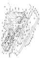
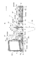
図1及び図2は、本発明の実施の形態に係る磁気カード発券機の構成を示す斜視図であり、図3は側面図、図4は上面図である。なお、各図において、磁気カードの発券口を符号Wで示し、この発券口W側を前方向X、右方向を符号Yで各々示している。
この磁気カード発券機10は、図1及び図2に示すように、磁気カードを発券するための一連の機構を具備する発券機構11と、この発券機構11が固定される一枚のベースプレート13とを備え、このベースプレート13が図示せぬフレームに固定されて全体が外装カバーで覆われる。
Hereinafter, embodiments of the present invention will be described with reference to the accompanying drawings.
1 and 2 are perspective views showing a configuration of a magnetic card ticketing machine according to an embodiment of the present invention, FIG. 3 is a side view, and FIG. 4 is a top view. In each figure, the ticket outlet of the magnetic card is indicated by the symbol W, the ticket outlet W side is indicated by the forward direction X, and the right direction is indicated by the symbol Y.
As shown in FIGS. 1 and 2, the magnetic card ticketing machine 10 includes a ticketing mechanism 11 including a series of mechanisms for issuing a magnetic card, a single base plate 13 to which the ticketing mechanism 11 is fixed, The base plate 13 is fixed to a frame (not shown) and is entirely covered with an exterior cover.

発券機構11は、複数個(本例では、3個)のユニットを備えて構成され、具体的には、磁気カードの供給機能を有した供給ユニット(磁気カード供給ユニット)20と、磁気カードの搬送及び排出機能を有した排出ユニット(カードセレクタとも言う)40と、磁気情報の書き込み及び読み取り機能を有した記録ユニット(エンコーダとも言う)60とを備えている。
これら供給ユニット20、排出ユニット40及び記録ユニット60は、配設される機構部品に合わせて前後長が異なる略同幅の板状フレームを備えて各々単一ユニットとして構成され、供給ユニット20、排出ユニット40、記録ユニット60の順に一列に配列されるようにベースプレート13に固定される。
The ticket issuing mechanism 11 includes a plurality of (in this example, three) units. Specifically, the ticket issuing mechanism 11 includes a supply unit (magnetic card supply unit) 20 having a magnetic card supply function, and a magnetic card. A discharge unit (also referred to as a card selector) 40 having a conveyance and discharge function and a recording unit (also referred to as an encoder) 60 having a function of writing and reading magnetic information are provided.
Each of the supply unit 20, the discharge unit 40, and the recording unit 60 is configured as a single unit with plate-like frames having substantially the same width and different longitudinal lengths according to the mechanical parts to be arranged. The unit 40 and the recording unit 60 are fixed to the base plate 13 so as to be arranged in a line in this order.

ベースプレート13は、略長方形に形成された金属板等の剛性を有する一枚の板部材で形成され、その短手方向の両端部にL字状に折り曲げて形成した足部13A、13Bを有し、この左右一対の足部13A、13Bの間に、発券機構11の載置スペースとなる長方形の平板部13Cが形成される。平板部13Cの左右には、複数のボス部14A、14B、14C及びねじ孔15A、15B、15Cが間隔を空けて形成される。
これら複数のボス部14A〜14Cは、上方に突出すると共に、供給ユニット20、排出ユニット40及び記録ユニット60の各々に対応する位置に設けられ、各ユニット20、40及び60を平板部13Cに配置する際に、各ユニット20、40及び60に設けられた孔部21、41(図示されず)61が各々挿通されることによって、各ユニット20、40及び60を位置決めする位置決め用ボスとして機能する。
The base plate 13 is formed of a single plate member having rigidity, such as a metal plate formed in a substantially rectangular shape, and has leg portions 13A and 13B formed by bending in an L shape at both ends in the short direction. Between the pair of left and right feet 13A and 13B, a rectangular flat plate portion 13C serving as a placement space for the ticketing mechanism 11 is formed. A plurality of boss portions 14A, 14B, 14C and screw holes 15A, 15B, 15C are formed on the left and right sides of the flat plate portion 13C at intervals.
The plurality of boss portions 14A to 14C protrude upward and are provided at positions corresponding to the supply unit 20, the discharge unit 40, and the recording unit 60, and the units 20, 40, and 60 are disposed on the flat plate portion 13C. In doing so, holes 21 and 41 (not shown) 61 provided in the units 20, 40 and 60 are respectively inserted, thereby functioning as positioning bosses for positioning the units 20, 40 and 60. .

ここで、図中、ボス部14Aが供給ユニット20の位置決め用ボスであり、ボス部14Bが排出ユニット40の位置決め用ボスであり、ボス部14Cが記録ユニット60の位置決め用ボスである。
本構成では、図1及び図2に示すように、ユニット20、40及び60毎に2個のボス部14A〜14Cを設けると共に、各ボス部14A〜14Cの間隔をユニット20、40及び60毎に異ならせている。このように2個のボス部14A〜14Cで位置決めすることによって、各ユニット20、40及び60の前後及び左右の位置を精度良く、かつ、簡易に位置決めすることができる。しかも、このユニット20、40及び60毎のボス部14A〜14Cの間隔を異ならせることによって、ユニット20、40及び60を間違ったボス部14A〜14Cに挿通してしまう事態を回避でき、組み立てミスを回避できる。なお、ボス部14A〜14Cの数を変更してもよい。
Here, in the figure, the boss portion 14A is a positioning boss of the supply unit 20, the boss portion 14B is a positioning boss of the discharge unit 40, and the boss portion 14C is a positioning boss of the recording unit 60.
In this configuration, as shown in FIGS. 1 and 2, two boss portions 14A to 14C are provided for each of the units 20, 40, and 60, and the intervals between the boss portions 14A to 14C are set to the units 20, 40, and 60, respectively. Different. By positioning with the two boss portions 14A to 14C in this way, the front and rear and left and right positions of each unit 20, 40 and 60 can be accurately and easily positioned. Moreover, by making the intervals of the boss portions 14A to 14C for each of the units 20, 40 and 60 different, it is possible to avoid a situation where the units 20, 40 and 60 are inserted into the wrong boss portions 14A to 14C, and an assembly error is caused. Can be avoided. Note that the number of the boss portions 14A to 14C may be changed.

また、ねじ孔15A〜15Cは、雌ねじに形成されており、上記ボス部14A〜14Cによって各ユニット20、40及び60を位置決めし、各ユニット20、40及び60がねじ17で該ねじ孔15A〜15Cに締結されることによって、ベースプレート13に固定される(図3、図4参照)。なお、ねじ孔15Aは供給ユニット20に形成されたねじ孔を示し、ねじ孔15Bは排出ユニット40に形成されたねじ孔を示し、ねじ孔15Cは記録ユニット60に形成されたねじ孔を示している。
図1及び図2に示すように、これらボス部14A〜14C及びねじ孔15A〜15Cは、ベースプレート13の平板部13Cの左右で前後方向に延びる直線上に形成されており、また、ボス部14A〜14Cについては排出ユニット40のボス部14Bを除いて、一方側(Y方向側)に集中して設けられる。これによれば、各ユニット20、40及び60をベースプレート13に位置決めする際の視認性及び作業性が向上し、位置決めし易くすることができる。なお、排出ユニット40のボス部14Bのみ左右に振り分け配置したのは、排出ユニット40の前後長が短いため、一方側(Y方向側)に集中配置し難いからである。
Further, the screw holes 15A to 15C are formed in the female screw, and the units 20, 40 and 60 are positioned by the boss portions 14A to 14C, and the units 20, 40 and 60 are screws 17 and the screw holes 15A to 15C. By being fastened to 15C, it is fixed to the base plate 13 (see FIGS. 3 and 4). The screw hole 15A indicates a screw hole formed in the supply unit 20, the screw hole 15B indicates a screw hole formed in the discharge unit 40, and the screw hole 15C indicates a screw hole formed in the recording unit 60. Yes.
As shown in FIGS. 1 and 2, the boss portions 14A to 14C and the screw holes 15A to 15C are formed on a straight line extending in the front-rear direction on the left and right of the flat plate portion 13C of the base plate 13, and the boss portion 14A. ˜14C are provided concentrated on one side (Y direction side) except for the boss portion 14B of the discharge unit 40. According to this, visibility and workability at the time of positioning each unit 20, 40, and 60 to the base plate 13 improve, and it can make it easy to position. Note that the reason why only the boss portion 14B of the discharge unit 40 is distributed to the left and right is that the front and rear length of the discharge unit 40 is short, so that it is difficult to concentrate on one side (Y direction side).

また、記録ユニット60には、発券機構11の各ユニット20、40及び60を統括制御するための主制御基板100が配置されている(後述する図5参照)。この主制御基板100は、ベースプレート13に固定される各ユニット20、40及び60に不図示のケーブルを介して電気的に接続される。ここで、主制御基板100を記録ユニット60に配置しているのは、記録ユニット60には、磁気情報の書き込み及び読み取りを行うためのヘッド部76を有する分、他のユニット20、40よりも主制御基板100に接続される電気部品が多くなり、主制御基板100を記録ユニット60に配置することで、記録ユニット60との間のケーブル長を短くし、かつ、記録ユニット60及び主制御基板100への作業性を確保できるからである。   The recording unit 60 is provided with a main control board 100 for overall control of the units 20, 40 and 60 of the ticket issuing mechanism 11 (see FIG. 5 described later). The main control board 100 is electrically connected to each unit 20, 40 and 60 fixed to the base plate 13 via a cable (not shown). Here, the main control board 100 is arranged in the recording unit 60 because the recording unit 60 has a head portion 76 for writing and reading magnetic information, compared to the other units 20 and 40. The number of electrical components connected to the main control board 100 increases, and the main control board 100 is arranged in the recording unit 60, thereby shortening the cable length between the recording unit 60 and the recording unit 60 and the main control board. This is because workability to 100 can be ensured.

また、図1及び図2中、符号13Dは、主制御基板100に設けられた図示せぬ切替スイッチ(具体的には、オプションプログラム設定用DIPスイッチ)を視認するための窓部であり、符号13Eは、排出ユニット40に対応する領域に設けられたカード排出用の開口部であり、符号13Fは、供給ユニット20のカード搬送ローラ35のクリアランス調整用ねじを回すための作業孔である。
また、符号13Gは、ベースプレート13を不図示のフレームに固定するためのねじ孔であり、符号13Hは、記録ユニット60のコネクタ部60A(図2参照)につなぐケーブルを通すケーブル通し孔であり、符号13I、13Jは、排出ユニット40のコネクタ部40A、40B、40C(図2参照)につなぐケーブルを通すケーブル通し孔であり、符号13K、13Lは、供給ユニット20のコネクタ部20A、20B(図2参照)につなぐケーブルを通すケーブル通し孔である。
Further, in FIG. 1 and FIG. 2, reference numeral 13D denotes a window portion for visually recognizing a changeover switch (not shown) (specifically, an optional program setting DIP switch) provided on the main control board 100. Reference numeral 13E denotes a card discharge opening provided in an area corresponding to the discharge unit 40, and reference numeral 13F denotes a work hole for turning a clearance adjusting screw of the card transport roller 35 of the supply unit 20.
Reference numeral 13G is a screw hole for fixing the base plate 13 to a frame (not shown), and reference numeral 13H is a cable through hole for passing a cable connected to the connector portion 60A (see FIG. 2) of the recording unit 60. Reference numerals 13I and 13J are cable through holes through which cables are connected to the connector sections 40A, 40B and 40C (see FIG. 2) of the discharge unit 40, and reference numerals 13K and 13L are connector sections 20A and 20B (see FIG. 2) is a cable through hole through which the cable to be connected is connected.

<供給ユニット>
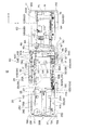
図5は、複数枚の磁気カード5を上下に重ねて収納するカートリッジ22を装着した状態の磁気カード発券機10の縦断面図である。
供給ユニット20は、磁気カード5を一枚ずつ外部(排出ユニット40側)へ供給するカード供給機能を有するユニットであり、上述のカートリッジ22を着脱可能に備えると共に、このカートリッジ22内の磁気カード5を一枚ずつ搬送する機能を有したディスペンサ24を備える。
ディスペンサ24は、図1及び図2に示すように、複数の金属板等の剛性を有する板部材を連結して構成した板状フレーム25を有し、この板状フレーム25は、左右一対の側板25A、25Bを有する。この側板25A、25B間には、前後方向に延びる磁気カード案内板25Cが配置される。また、左右一対の側板25A、25Bの後部及び中間部が上方に延在し、後部間が後板26Aで連結され、中間部間が中間板26Bで連結され、この後板26A及び中間板26Bに囲まれるスペースにカートリッジ22が挿入される。
<Supply unit>
FIG. 5 is a longitudinal sectional view of the magnetic card issuing machine 10 in a state in which a cartridge 22 for storing a plurality of magnetic cards 5 stacked one above the other is mounted.
The supply unit 20 is a unit having a card supply function for supplying the magnetic cards 5 one by one to the outside (on the discharge unit 40 side). The supply unit 20 includes the above-described cartridge 22 in a detachable manner, and the magnetic card 5 in the cartridge 22. Is provided with a dispenser 24 having a function of conveying the sheets one by one.
As shown in FIGS. 1 and 2, the dispenser 24 has a plate-like frame 25 formed by connecting a plurality of rigid plate members such as metal plates, and the plate-like frame 25 includes a pair of left and right side plates. 25A and 25B. A magnetic card guide plate 25C extending in the front-rear direction is disposed between the side plates 25A and 25B. Further, the rear and intermediate portions of the pair of left and right side plates 25A and 25B extend upward, the rear portions are connected by a rear plate 26A, and the intermediate portions are connected by an intermediate plate 26B. The rear plates 26A and the intermediate plates 26B The cartridge 22 is inserted into the space surrounded by.

また、左右一対の側板25A、25Bには、駆動モータ27と、駆動モータ27の駆動によりカートリッジ22から磁気カード5を引き出すクランク機構28(図3参照)と、駆動モータ27の駆動によりクランク機構28にて引き出された磁気カード5を搬送するカード搬送機構29(図5参照)とが配設される。
詳述すると、図3及び図4に示すように、一方(Y方向側)の側板25Aには、駆動モータ27の駆動力を伝達する減速歯車伝達機構30が設けられ、そのうちの最も減速された歯車30A(図4参照)には、楕円回転体32が一体に形成され、この楕円回転体32にピン連結された単一の腕部33を介してカード引出体34を前後に往復移動させ、これにより、磁気カード5を引き出すクランク機構28が構成される。
また、減速歯車伝達機構30の楕円回転体32を回転駆動させる減速歯車30B(図4参照)には、側板25A、25B間に回転自在に設けられたカード搬送ローラ35(図4参照)が連結され、減速歯車30Bの回転によりカード搬送ローラ35を回転させて磁気カード5を搬送する搬送機構29が構成される。
The pair of left and right side plates 25A and 25B includes a drive motor 27, a crank mechanism 28 (see FIG. 3) for pulling out the magnetic card 5 from the cartridge 22 by driving the drive motor 27, and a crank mechanism 28 by driving the drive motor 27. And a card transport mechanism 29 (see FIG. 5) for transporting the magnetic card 5 drawn out in step.
More specifically, as shown in FIGS. 3 and 4, the side plate 25A on one side (Y direction side) is provided with a reduction gear transmission mechanism 30 for transmitting the driving force of the drive motor 27, and the speed reduction is most reduced. The gear 30A (see FIG. 4) is integrally formed with an elliptical rotator 32, and the card drawer 34 is reciprocated back and forth via a single arm 33 pin-connected to the elliptical rotator 32. Thereby, the crank mechanism 28 which draws out the magnetic card 5 is configured.
In addition, a card conveying roller 35 (see FIG. 4) rotatably provided between the side plates 25A and 25B is connected to the reduction gear 30B (see FIG. 4) that rotationally drives the elliptical rotating body 32 of the reduction gear transmission mechanism 30. Thus, the conveyance mechanism 29 is configured to convey the magnetic card 5 by rotating the card conveyance roller 35 by the rotation of the reduction gear 30B.

ここで、カード引出体34は、左右一対の側板25A、25B間のカートリッジ22下方(磁気カード案内板25Cの下方)で前後に移動自在に配設され、腕部33により前後方向に往復移動する。また、このカード引出体34には、前方向Xに移動した際に、カートリッジ22内の最も下に位置する磁気カード5の後端に当接して該カード5を引き出し可能な左右一対の突出部34A(図1、図2参照)を有している。また、このカード引出体34は、付勢ばね(付勢部材)34B(図5参照)により供給ユニット20の後方側へ付勢される。
このため、このカード引出体34が、クランク機構28によって付勢ばね34Bの付勢力に抗して前方向Xへ移動した場合に、突出部34Aがカートリッジ22内の最も下の磁気カード5の後端に当接して該カード5を前方向Xに引き出す。また、磁気カード5を引き出した後は、カード引出体34が、クランク機構28の駆動と付勢ばね34Bの付勢力とによって、突出部34Aがカートリッジ22内の磁気カード5より後方となる位置(正規停止位置)へ移動する。
Here, the card drawer 34 is disposed movably back and forth below the cartridge 22 between the pair of left and right side plates 25A and 25B (below the magnetic card guide plate 25C), and reciprocally moves back and forth by the arm portion 33. . Further, the card drawer 34 has a pair of left and right protrusions that can contact the rear end of the magnetic card 5 located at the bottom of the cartridge 22 and pull out the card 5 when moved in the front direction X. 34A (see FIGS. 1 and 2). The card drawer 34 is urged toward the rear side of the supply unit 20 by an urging spring (urging member) 34B (see FIG. 5).
Therefore, when the card drawer 34 is moved in the forward direction X against the urging force of the urging spring 34B by the crank mechanism 28, the protrusion 34A is located behind the lowermost magnetic card 5 in the cartridge 22. The card 5 is pulled out in the forward direction X in contact with the end. In addition, after the magnetic card 5 is pulled out, the card drawer 34 is positioned so that the protruding portion 34A is behind the magnetic card 5 in the cartridge 22 by the drive of the crank mechanism 28 and the urging force of the urging spring 34B ( Move to the regular stop position.

このように、この供給ユニット20では、単一の駆動モータ27で、クランク機構28の駆動と、カード搬送機構29(カード搬送ローラ35)の駆動とを行い、すなわち、磁気カード5の引き出しと、磁気カード5の搬送との二つの動作を行うので、複数個のモータを使用する場合に比して部品点数を低減でき、供給ユニット20の小型化が可能である。
また、この供給ユニット20では、図1及び図2に示すように、左右の側板25A、25Bの下部を外側に折り曲げて左右一対の足部25D、25Eを形成し、この左右の足部25D、25Eに、ベースプレート13のボス部14A及びねじ孔15Aに対応する孔部を形成している。この左右の側板25A、25Bは、上記したように、上記機構部品の支持部材として機能するものであり、この支持部材を直接ベースプレート13に位置決めしてねじ固定するので、ベースプレート13に対する各機構部品の位置決めを精度良く行うことができる。
As described above, in the supply unit 20, the single drive motor 27 drives the crank mechanism 28 and the card transport mechanism 29 (card transport roller 35), that is, pulls out the magnetic card 5. Since the two operations of carrying the magnetic card 5 are performed, the number of parts can be reduced as compared with the case of using a plurality of motors, and the supply unit 20 can be downsized.
Further, in the supply unit 20, as shown in FIGS. 1 and 2, the lower portions of the left and right side plates 25A, 25B are bent outward to form a pair of left and right feet 25D, 25E, and the left and right feet 25D, A hole corresponding to the boss 14A and the screw hole 15A of the base plate 13 is formed in 25E. As described above, the left and right side plates 25A and 25B function as support members for the mechanical parts. Since the support members are directly positioned and fixed to the base plate 13 with screws, Positioning can be performed with high accuracy.

ところで、上記のように、上下に重ねられた磁気カード5の中から一枚の磁気カード5を引き出す構成の場合、引き出す磁気カード5の上に重なる磁気カード5が摩擦力や吸着等で同時に引き出されてしまう場合があり、かかる事態を回避するカード分離機構が必要になる。この場合、一枚の磁気カード5だけが通る隙間を設ける構成が考えられるが、上下に重ねられた複数枚の磁気カード5の中には、反りが生じたり、カード積載時に作用した力でカード端面がゆがんだ状態の磁気カード5が含まれるため、カード一枚分の隙間にした場合は、反りやゆがみが生じた磁気カード5が通過できず、磁気カード5の引っ掛かりや磁気カード5の傷つきが生じてしまう。一方、反りやゆがみが生じた磁気カード5が十分に通過可能な隙間にした場合は、複数枚の磁気カード5がその隙間を通過してしまうおそれが生じてしまう。
そこで、本実施形態では、反りやゆがみが生じた磁気カード5についても一枚の磁気カードを分離できるカード分離機構110を構成している。
By the way, as described above, in the case of a configuration in which one magnetic card 5 is pulled out from the magnetic cards 5 stacked one above the other, the magnetic card 5 overlapping on the magnetic card 5 to be pulled out is simultaneously pulled out by frictional force, adsorption or the like. A card separation mechanism that avoids such a situation is required. In this case, a configuration in which a gap through which only one magnetic card 5 passes is conceivable. However, a plurality of magnetic cards 5 stacked one above the other are warped, or the card is exerted by the force applied when loading the cards. Since the magnetic card 5 with the end face distorted is included, when the gap is made for one card, the magnetic card 5 with warping or distortion cannot pass, and the magnetic card 5 is caught or damaged. Will occur. On the other hand, if the gap is such that the magnetic card 5 having warpage or distortion is sufficiently passed, there is a risk that a plurality of magnetic cards 5 may pass through the gap.
Therefore, in the present embodiment, the card separation mechanism 110 is configured that can separate one magnetic card even with respect to the magnetic card 5 in which warping or distortion has occurred.

<カード分離機構>
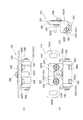
図6(A)(B)はカード分離機構110を周辺構成と共に示す図であり、図7(A)(B)(C)はカード分離機構110の三面図(平面図、側面図、上面図)であり、図8(A)(B)はカード分離機構110の斜視図である。
このカード分離機構110は、図5に示すように、左右の側板25A、25B間に配置された中間板26Bの下部を折り曲げて形成した板部111に支持されている。この板部111は、図6(A)(B)に示すように、中間板26Bの下部をカートリッジ22の反対側(前方向X)に屈曲させた水平板部111Aと、この水平板部111Aの端部から屈曲した下方に延びる下方板部111Bとを有した略L字断面に形成され、この下方板部111Bにカード分離機構110が固定されることで、カード分離機構110がカートリッジ22の出口近傍に配置される。なお、図6中、符号37は、磁気カード5の有無を検出するためのリミットスイッチである。以下に述べる各方向は、このカード分離機構110の取付状態での各方向に従うものとする。
<Card separation mechanism>
FIGS. 6A and 6B are views showing the card separation mechanism 110 together with the peripheral configuration. FIGS. 7A, 7B and 7C are three views (a plan view, a side view and a top view) of the card separation mechanism 110. FIG. 8A and 8B are perspective views of the card separation mechanism 110. FIG.
As shown in FIG. 5, the card separation mechanism 110 is supported by a plate portion 111 formed by bending a lower portion of an intermediate plate 26B disposed between the left and right side plates 25A and 25B. As shown in FIGS. 6A and 6B, the plate portion 111 includes a horizontal plate portion 111A in which a lower portion of the intermediate plate 26B is bent to the opposite side (front direction X) of the cartridge 22, and the horizontal plate portion 111A. The card separation mechanism 110 is fixed to the lower plate portion 111B by fixing the card separation mechanism 110 to the cartridge 22 so that the card separation mechanism 110 can be Located near the exit. In FIG. 6, reference numeral 37 denotes a limit switch for detecting the presence or absence of the magnetic card 5. Each direction described below follows each direction when the card separation mechanism 110 is attached.

このカード分離機構110は、図7及び図8に示すように、上下に延びる左右一対の長孔120A、120Bを形成した支持板120を備え、この支持板120の長孔120A、120Bの間には、略コ字状に形成されたストッパ形成体125がねじ126で固定される。また、支持板120は、ストッパ形成体125が上方から当接する当接部120Cを備え、ストッパ形成体125がこの当接部120Cに当接した状態でねじ126で固定されることによって、ストッパ形成体125の上下位置が精度良く位置決めされる。
このストッパ形成体125は、支持板120の下方で略直角に屈曲して延びる左右一対のストッパ130(図8(B)参照)を備えている。
As shown in FIGS. 7 and 8, the card separating mechanism 110 includes a support plate 120 having a pair of left and right elongated holes 120A and 120B extending vertically, and the support plate 120 is provided between the elongated holes 120A and 120B. The stopper forming body 125 formed in a substantially U shape is fixed with a screw 126. Further, the support plate 120 includes a contact portion 120C with which the stopper forming body 125 contacts from above, and is fixed with a screw 126 in a state where the stopper forming body 125 is in contact with the contact portion 120C. The vertical position of the body 125 is accurately positioned.
This stopper forming body 125 includes a pair of left and right stoppers 130 (see FIG. 8B) that bend and extend substantially perpendicularly below the support plate 120.

また、この支持板120は、上記ストッパ130の左右に位置する左右一対の折り曲げ部120D、120Eを備える。この左右一対の折り曲げ部120D、120Eには、上下方向に延在する長孔120F(図7(C)参照)が形成され、左右の長孔120Fには、左右一対の折り曲げ部120D、120E間に収まるように配置された円筒部材135の両端軸が上下方向に移動自在に挿通される。なお、図中、符号136は、円筒部材135の両端軸に装着された抜け止め部材である。さらに、支持板120には、上記円筒部材135の上面に当接するように板ばね137がねじ138で固定され、この板ばね137により円筒部材135が下方に付勢される。   The support plate 120 includes a pair of left and right bent portions 120D and 120E located on the left and right sides of the stopper 130. A long hole 120F (see FIG. 7C) extending in the vertical direction is formed in the pair of left and right bent portions 120D and 120E, and the pair of left and right bent portions 120D and 120E is formed in the left and right long holes 120F. Both end shafts of the cylindrical member 135 arranged so as to fit in the shaft are inserted so as to be movable in the vertical direction. In the figure, reference numeral 136 denotes a retaining member attached to both end shafts of the cylindrical member 135. Further, a leaf spring 137 is fixed to the support plate 120 with a screw 138 so as to contact the upper surface of the cylindrical member 135, and the cylindrical member 135 is urged downward by the leaf spring 137.

この円筒部材135には、図7(A)及び図8(B)に示すように、ストッパ形成体125から延びる左右一対のストッパ130との干渉を避けるための左右一対の切り欠き部135Aが設けられる。このため、図7(B)及び図8(B)に示すように、板ばね137により付勢された円筒部材135の下面は、ストッパ130の下面よりも下方に位置する。なお、このカード分離機構110を構成する各部品は、金属材または樹脂材などの剛性を有する材料で形成される。   As shown in FIGS. 7A and 8B, the cylindrical member 135 is provided with a pair of left and right cutouts 135A for avoiding interference with the pair of left and right stoppers 130 extending from the stopper forming body 125. It is done. Therefore, as shown in FIGS. 7B and 8B, the lower surface of the cylindrical member 135 biased by the leaf spring 137 is positioned below the lower surface of the stopper 130. Each component constituting the card separation mechanism 110 is formed of a rigid material such as a metal material or a resin material.

このカード分離機構110は、図5及び図6に示すように、円筒部材135をカートリッジ22の出口側に向けてねじ140で取り付けられる。この場合、ねじ140を通すねじ孔が上下に延びる長孔120A、120Bに形成されているので、カード分離機構110の固定位置を上下に微調整可能である。具体的には、カード分離機構110が有する左右のストッパ130の下面と、磁気カード5が搬送される磁気カード案内板25Cとの間の隙間(高さ)が、反りや歪みのない一枚の磁気カード5は通過するが二枚の磁気カードは通過しない隙間、つまり、反りや歪みのないカード一枚分の厚さに対し微少の余裕隙間を持たせた隙間に調整される。この隙間調整は、シックネスゲージを使用することで予め定めた隙間に精度良く調整できる。   As shown in FIGS. 5 and 6, the card separating mechanism 110 is attached with a screw 140 with the cylindrical member 135 facing the outlet side of the cartridge 22. In this case, since the screw hole for passing the screw 140 is formed in the elongated holes 120A and 120B extending vertically, the fixing position of the card separation mechanism 110 can be finely adjusted up and down. Specifically, the gap (height) between the lower surfaces of the left and right stoppers 130 of the card separation mechanism 110 and the magnetic card guide plate 25C to which the magnetic card 5 is conveyed is a single sheet without warping or distortion. The gap is adjusted so that the magnetic card 5 passes but the two magnetic cards do not pass, that is, a gap having a slight margin with respect to the thickness of one card without warping or distortion. This gap adjustment can be accurately adjusted to a predetermined gap by using a thickness gauge.

供給ユニット20において、駆動モータ27の駆動によりクランク機構28にて引き出された一番下の磁気カード5は、図6(A)に示すように、下方に付勢された円筒部材135と磁気カード案内板25Cとの間に挿入されるので、磁気カード5の先端が円筒部材135で付勢される。円筒部材135で下方に付勢されると、磁気カード5の先端が円筒部材135と磁気カード案内板25Cとの間に挟まれて平面化され、この平面化された状態でストッパ130側へ搬送されるので、図6(B)に示すように、一番下の磁気カード5だけがストッパ130の下側に案内される。
すなわち、このカード分離機構110は、上記円筒部材135により磁気カード5の先端を付勢してストッパ130の下側に案内する案内機構110Xを備える。この案内機構110Xによれば、磁気カード5の先端を付勢した状態でストッパ130の下側に案内するので、反りや歪みが生じた磁気カード5の場合でも、この磁気カード5が反りや歪みのないカード一枚分の厚さに平面化し、ストッパ130の下側を通過させることができる。
In the supply unit 20, the lowermost magnetic card 5 drawn by the crank mechanism 28 by the drive of the drive motor 27 includes a cylindrical member 135 urged downward and a magnetic card as shown in FIG. Since it is inserted between the guide plate 25 </ b> C, the tip of the magnetic card 5 is urged by the cylindrical member 135. When urged downward by the cylindrical member 135, the tip of the magnetic card 5 is flattened by being sandwiched between the cylindrical member 135 and the magnetic card guide plate 25C, and conveyed to the stopper 130 side in this flattened state. Therefore, as shown in FIG. 6B, only the bottom magnetic card 5 is guided to the lower side of the stopper 130.
That is, the card separation mechanism 110 includes a guide mechanism 110X that biases the tip of the magnetic card 5 by the cylindrical member 135 and guides it to the lower side of the stopper 130. According to the guide mechanism 110X, the magnetic card 5 is guided to the lower side of the stopper 130 with the tip of the magnetic card 5 being urged. Therefore, even when the magnetic card 5 is warped or distorted, the magnetic card 5 is warped or distorted. It can be flattened to the thickness of a single card without any gap and passed under the stopper 130.

これによれば、ストッパ130下側の余裕隙間を微少にできるから、図6(A)に示すように、二枚の磁気カード5が引き出された場合でも、二枚目の磁気カード5をストッパ130により必ず通過を阻止でき、特に薄い磁気カード5が二枚同時に挿入されてしまう事態も確実に防止できる。従って、磁気カード5に反りや歪みのある場合、及び、反りや歪みのない場合のいずれの場合でも、一枚の磁気カード5だけを確実に分離することができ、かつ、反りや歪みが生じた磁気カード5を引っ掛けて動作停止に至る事態や、磁気カード5が傷つく事態を防止できる。   According to this, since the margin gap below the stopper 130 can be made small, even when the two magnetic cards 5 are pulled out as shown in FIG. The passage can be surely prevented by 130, and the situation where two thin magnetic cards 5 are inserted simultaneously can be surely prevented. Therefore, even when the magnetic card 5 is warped or distorted, or when there is no warpage or distortion, only one magnetic card 5 can be reliably separated, and warping or distortion occurs. It is possible to prevent a situation in which the magnetic card 5 is hooked and the operation is stopped or the magnetic card 5 is damaged.

<排出ユニット>
排出ユニット40は、磁気カード5の搬送及び排出機能を有するユニットであり、図1及び図2に示すように、金属板等の剛性を有する板部材からなるメインフレーム(板状フレーム)42と、このメインフレーム42に回動自在に支持されるサブフレーム(以下、回動フレームという)44とを有している。
より具体的には、メインフレーム42は、図4に示すように、左右一対の側板42A、42Bを有し、この側板42A、42B間には、左右方向に延びる回動軸45が回動自在に支持され、この回動軸45に回動フレーム44が固定されることで、回動軸45と一体に回動フレーム44が回動自在に支持される。
メインフレーム42には、回動用駆動モータ46と、この回動用駆動モータ46の駆動により回動軸45を回動させるベルト式の動力伝達機構47とが設けられ、この駆動モータ46を回動することにより、回動フレーム44が、図9(A)に示す水平位置(以下、搬送位置という)から90度回転して、図9(B)に示す垂直位置(以下、排出位置という)へと回動し、駆動モータ46を逆回転すれば、再び搬送位置へと戻すことができる。また、メインフレーム42には、回動フレーム44が搬送位置に移動したことを検出するためのリミットスイッチ49(図1、図2参照)と、排出位置に移動したことを検出するためのリミットスイッチ50(図1、図2参照)とが配置される。
<Discharge unit>
The discharge unit 40 is a unit having a function of conveying and discharging the magnetic card 5, and as shown in FIGS. 1 and 2, a main frame (plate frame) 42 made of a plate member having rigidity such as a metal plate, The main frame 42 has a sub frame (hereinafter referred to as a rotation frame) 44 that is rotatably supported.
More specifically, as shown in FIG. 4, the main frame 42 has a pair of left and right side plates 42A and 42B, and a rotation shaft 45 extending in the left and right direction is rotatable between the side plates 42A and 42B. The rotation frame 44 is fixed to the rotation shaft 45, so that the rotation frame 44 is rotatably supported integrally with the rotation shaft 45.
The main frame 42 is provided with a rotation drive motor 46 and a belt-type power transmission mechanism 47 that rotates the rotation shaft 45 by driving the rotation drive motor 46, and rotates the drive motor 46. As a result, the rotating frame 44 rotates 90 degrees from the horizontal position (hereinafter referred to as the transport position) shown in FIG. 9 (A) to the vertical position (hereinafter referred to as the discharge position) shown in FIG. 9 (B). If the drive motor 46 rotates in the reverse direction, it can be returned to the transport position again. The main frame 42 includes a limit switch 49 (see FIGS. 1 and 2) for detecting that the rotating frame 44 has moved to the transport position, and a limit switch for detecting that the rotating frame 44 has moved to the discharge position. 50 (see FIGS. 1 and 2).

回動フレーム44は、メインフレーム42より幅狭の間隔で離間する左右一対の側板44A、44Bを有しており、この左右一対の側板44A、44Bが回動軸45に各々固定される。この回動フレーム44の側板44A、44B間には、図5に示すように、上下一対の磁気カード案内板52(図5参照)と、この磁気カード案内板52間の磁気カードを搬送するための上下一対のカード搬送ローラ54と、駆動モータ56(図3、図9参照)とが配設される。
また、一方(Y方向側)の側板44Aには、図9に示すように、駆動モータ56の駆動力を、カード搬送ローラ54が各々連結された歯車54Aに各々伝達する歯車伝達機構57が設けられる。これによって、駆動モータ46の駆動によりカード搬送ローラ54を回転駆動させて磁気カード5を磁気カード案内板52の間で搬送する搬送機構が構成され、この搬送機構は、図9(A)に示す搬送位置の場合、前方向Xに磁気カード5を搬送し、排出位置の場合(図9(B)の場合)には、略鉛直方向(符号Zで示す方向)に磁気カード5を搬送(排出)可能に構成される。
The rotating frame 44 has a pair of left and right side plates 44A and 44B that are spaced apart from the main frame 42 at a narrower interval, and the pair of left and right side plates 44A and 44B are fixed to the rotating shaft 45, respectively. As shown in FIG. 5, a pair of upper and lower magnetic card guide plates 52 (see FIG. 5) and a magnetic card between the magnetic card guide plates 52 are conveyed between the side plates 44A and 44B of the rotating frame 44. A pair of upper and lower card transport rollers 54 and a drive motor 56 (see FIGS. 3 and 9) are disposed.
Further, as shown in FIG. 9, a gear transmission mechanism 57 for transmitting the driving force of the driving motor 56 to the gears 54A to which the card conveying rollers 54 are connected is provided on one side plate 44A (Y direction side). It is done. As a result, a conveyance mechanism for conveying the magnetic card 5 between the magnetic card guide plates 52 by rotating the card conveyance roller 54 by driving the drive motor 46 is configured. This conveyance mechanism is shown in FIG. In the case of the transfer position, the magnetic card 5 is transferred in the forward direction X, and in the case of the discharge position (in the case of FIG. 9B), the magnetic card 5 is transferred (discharged) in a substantially vertical direction (direction indicated by reference sign Z). ) Can be configured.

また、この排出ユニット40では、図1及び図2に示すように、メインフレーム42の左右の側板42A、42Bの下部を内側に折り曲げて左右一対の足部34D、34E(図4参照)を形成し、この左右の足部34D、34Eに、ベースプレート13のボス部14B及びねじ孔15Bに対応する孔部を形成している。この左右の側板42A、42Bは、上記した各部品の支持部材として機能するものであり、この支持部材を直接ベースプレート13へ位置決めしてねじ固定するので、ベースプレート13に対する各機構部品の位置決めを精度良く行うことができる。   Further, in the discharge unit 40, as shown in FIGS. 1 and 2, the lower portions of the left and right side plates 42A and 42B of the main frame 42 are bent inward to form a pair of left and right feet 34D and 34E (see FIG. 4). In addition, holes corresponding to the boss portions 14B and the screw holes 15B of the base plate 13 are formed in the left and right foot portions 34D and 34E. The left and right side plates 42A and 42B function as support members for the above-described components, and the support members are directly positioned on the base plate 13 and fixed with screws, so that the positioning of the mechanical components with respect to the base plate 13 can be accurately performed. It can be carried out.

<記録ユニット>
記録ユニット60は、磁気カード5に記録された情報の書き込み及び読み取り機能を有するユニットであり、図1及び図2に示すように、金属板等の剛性を有する板部材からなる略直方体形状の板状フレーム62を有し、この板状フレーム62は、左右一対の側板62A、62Bを有し、この側板62A、62B間に、前後方向に延びる磁気カード案内板64が配設されると共に、この磁気カード案内板64に案内される磁気カード5を搬送可能に上下一対のカード搬送ローラ66、68及び70(図5参照)が前後に間隔を空けて3組配置されている。
これら3組のカード搬送ローラ66、68、70は、一方(Y方向側)の側板62Aの外側に形成された歯車伝達機構72(図1、図3参照)を介して、側板62A、62B間に配設された駆動モータ74(図1、図2参照)の駆動力により等速で回転駆動される。この回転駆動の方向によって、磁気カード5を、板状フレーム62の後側開口から前側開口(つまり、発券口W)に向かって前方向Xに搬送したり、逆方向(−X方向)へ搬送することが可能に構成されている。
<Recording unit>
The recording unit 60 is a unit having a function of writing and reading information recorded on the magnetic card 5, and as shown in FIGS. 1 and 2, is a substantially rectangular parallelepiped plate made of a rigid plate member such as a metal plate. The plate-like frame 62 has a pair of left and right side plates 62A and 62B. A magnetic card guide plate 64 extending in the front-rear direction is disposed between the side plates 62A and 62B. Three pairs of upper and lower card transport rollers 66, 68 and 70 (see FIG. 5) are arranged at intervals in the front and rear directions so that the magnetic card 5 guided by the magnetic card guide plate 64 can be transported.
These three sets of card transport rollers 66, 68, 70 are connected between the side plates 62A, 62B via a gear transmission mechanism 72 (see FIGS. 1 and 3) formed on the outer side of one (Y direction side) side plate 62A. Is driven to rotate at a constant speed by the driving force of a drive motor 74 (see FIGS. 1 and 2) disposed in the motor. Depending on the direction of this rotational drive, the magnetic card 5 is transported in the front direction X from the rear opening of the plate-like frame 62 toward the front opening (that is, the ticketing slot W) or in the reverse direction (−X direction). It is configured to be able to.

ここで、前後略中央に位置する上下一対のカード搬送ローラ68は上下で幅が異なる。以下、説明の便宜上、下側ローラを符号68Aを付して示し、上側ローラを符号68Bを付して説明する。図1及び図2に示すように、下側のカード搬送ローラ68Aは、上側のカード搬送ローラ68Bに比して幅狭のローラに形成されると共に、上側のカード搬送ローラ68Bの一端側に寄せて配置され、上側のカード搬送ローラ68Bの他端側に対向する領域には、磁気情報の書き込み及び読み取りを行うヘッド部76が配置される(図1参照)。また、磁気カード案内板64には、磁気カード5の情報記録エリアが上記ヘッド部76を通るように磁気カード5を案内する前後方向に延びる凸条部64Aが設けられている。   Here, the pair of upper and lower card transport rollers 68 positioned substantially in the front and rear are different in width in the vertical direction. Hereinafter, for convenience of explanation, the lower roller is denoted by reference numeral 68A, and the upper roller is denoted by reference numeral 68B. As shown in FIGS. 1 and 2, the lower card transport roller 68A is formed as a narrower roller than the upper card transport roller 68B, and is moved toward one end of the upper card transport roller 68B. In a region facing the other end of the upper card transport roller 68B, a head unit 76 for writing and reading magnetic information is disposed (see FIG. 1). Further, the magnetic card guide plate 64 is provided with a ridge portion 64 </ b> A extending in the front-rear direction for guiding the magnetic card 5 so that the information recording area of the magnetic card 5 passes through the head portion 76.

また、この記録ユニット60においても、図1及び図2に示すように、板状フレーム62の左右の側板62A、62Bの下部を外側に折り曲げて左右一対の足部62D、62Eを形成し、この左右の足部62D、62Eに、ベースプレート13のボス部14C及びねじ孔15Cに対応する孔部を形成している。この左右の側板62A、62Bは、上記した各部品の支持部材として機能するものであり、この支持部材を直接ベースプレート13へ位置決めしてねじ固定するので、ベースプレート13に対する各機構部品の位置決めを精度良く行うことができる。   Also in the recording unit 60, as shown in FIGS. 1 and 2, the lower portions of the left and right side plates 62A and 62B of the plate-like frame 62 are bent outward to form a pair of left and right feet 62D and 62E. Holes corresponding to the boss portions 14C and the screw holes 15C of the base plate 13 are formed in the left and right foot portions 62D and 62E. The left and right side plates 62A and 62B function as support members for the above-described components. Since the support members are directly positioned and fixed to the base plate 13 with screws, the positioning of the mechanical components with respect to the base plate 13 is accurately performed. It can be carried out.

<位置検出センサ>
この磁気カード発券機10の各ユニット20、40及び60には、磁気カード5等の位置を検出する複数の位置検出センサが配置されている。
図10は、磁気カード発券機10を位置検出センサと共に模式的に示した上面図である。この図に示すように、供給ユニット20には、カートリッジ22内の磁気カード5を引き出すカード引出体34が正規停止位置が否かを検出する位置検出センサS1と、磁気カード5がカード搬送ローラ35上流側(後方向−X側)にあるか否かを検出する位置検出センサS2とが配置される。また、排出ユニット40には、磁気カード5がカード搬送ローラ54下流側(前方向X側)にあるか否かを検出する位置検出センサS3が配置される。また、記録ユニット60には、磁気カード5への書き込み開始位置、書き込み終了位置、読み取り開始位置、読み取り終了位置等の各位置を検出するための複数(本例では6個)の位置検出センサS4〜S9が配置される。なお、これら位置検出センサS1〜S9には、例えば光反射式または光透過式或いは接触検知式が適用される。
<Position detection sensor>
A plurality of position detection sensors for detecting the position of the magnetic card 5 and the like are arranged in each unit 20, 40 and 60 of the magnetic card ticketing machine 10.
FIG. 10 is a top view schematically showing the magnetic
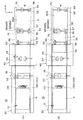
 card ticketing machine 10 together with a position detection sensor. As shown in this figure, the supply unit 20 includes a position detection sensor S1 for detecting whether or not the card drawer 34 for pulling out the magnetic card 5 in the cartridge 22 is in the normal stop position, and the magnetic card 5 is connected to the card transport roller 35. A position detection sensor S2 that detects whether or not it is on the upstream side (rear direction-X side) is disposed. Further, the discharge unit 40 is provided with a position detection sensor S3 that detects whether or not the magnetic card 5 is on the downstream side (front side X side) of the card transport roller 54. The recording unit 60 includes a plurality (six in this example) of position detection sensors S4 for detecting each position such as a write start position, a write end position, a read start position, and a read end position on the magnetic card 5. To S9 are arranged. For example, a light reflection type, a light transmission type, or a contact detection type is applied to the position detection sensors S1 to S9.

<磁気カード発券機の動作>
次に、磁気カード発券機10の動作を図10〜図13を参照しながら説明する。前提として、この磁気カード発券機10では、図10(A)に示すように、カートリッジ22内の磁気カード5が、カード前端面5Aを発券口Wの反対側に向け、カード後端面5Bを発券口W側に向けて装填されている。また、以下の説明においては、カード規格の見地から、磁気カード5が発券口W側に向かう場合(カード後端面5Bを前にして移動する場合)を、逆方向への搬送(逆搬送)と表記し、磁気カード5が発券口Wの反対側に向かう場合(カード前端面5Aを前にして移動する場合)を正方向への搬送(正搬送)と表記する。
また、各位置検出センサS1〜S9が、カード引出体34や磁気カード5を検出している検出状態をONと表記し、非検出状態をOFFと表記する。なお、デフォルト状態では排出ユニット40の回動フレーム44は搬送位置に保持されているものとする。
<Operation of magnetic card issuing machine>
Next, the operation of the magnetic card ticketing machine 10 will be described with reference to FIGS. As a premise, in this magnetic card ticketing machine 10, as shown in FIG. 10A, the magnetic card 5 in the cartridge 22 faces the card front end face 5A to the opposite side of the ticketing slot W, and the card rear end face 5B is issued. It is loaded toward the mouth W side. In the following description, from the viewpoint of the card standard, when the magnetic card 5 is directed toward the ticket issuing slot W (when moving with the card rear end surface 5B in front), conveyance in the reverse direction (reverse conveyance). The case where the magnetic card 5 is directed to the opposite side of the ticketing slot W (in the case of moving with the card front end face 5A in front) is referred to as conveyance in the forward direction (normal conveyance).
Further, a detection state in which each of the position detection sensors S1 to S9 detects the card drawer 34 and the magnetic card 5 is described as ON, and a non-detection state is described as OFF. In the default state, the rotation frame 44 of the discharge unit 40 is assumed to be held at the transport position.

この磁気カード発券機10において、発券開始の指示を入力すると、主制御基板100は、供給ユニット20の駆動モータ27(図4参照)を駆動させる(図10(A)参照)。この場合、クランク機構28及びカード搬送ローラ35が駆動されるので、磁気カード5がカートリッジ22から前方向Xに引き出され、カード出口のカード分離機構110にて一枚の磁気カード5だけが分離され、カード搬送ローラ35により前方向Xに逆搬送されて排出ユニット40のカード搬送ローラ54へと搬送される(図10(B)参照)。   In the magnetic card ticketing machine 10, when a ticketing start instruction is input, the main control board 100 drives the drive motor 27 (see FIG. 4) of the supply unit 20 (see FIG. 10A). In this case, since the crank mechanism 28 and the card transport roller 35 are driven, the magnetic card 5 is pulled out from the cartridge 22 in the forward direction X, and only one magnetic card 5 is separated by the card separation mechanism 110 at the card exit. Then, it is reversely conveyed in the forward direction X by the card conveying roller 35 and conveyed to the card conveying roller 54 of the discharge unit 40 (see FIG. 10B).

この供給ユニット20での逆搬送中に、供給ユニット20の位置検出センサS2がONになると、主制御基板100は、排出ユニット40の駆動モータ56(図3参照)を駆動させ、磁気カード5を供給ユニット20から排出ユニット40へと逆搬送させる。その後、供給ユニット20の位置検出センサS1がONになると、主制御基板100は、供給ユニット20の駆動モータ27を停止させる。
次いで、主制御基板100は、磁気カード5が排出ユニット40のカード搬送ローラ54を通過して排出ユニット40の位置検出センサS3がONになると、記録ユニット60の駆動モータ74(図4参照)を駆動させ、その後、位置検出センサS3がOFFになると、排出ユニット40の駆動モータ56を停止させる。
When the position detection sensor S2 of the supply unit 20 is turned on during the reverse conveyance in the supply unit 20, the main control board 100 drives the drive motor 56 (see FIG. 3) of the discharge unit 40, and the magnetic card 5 is moved. Reverse feed from the supply unit 20 to the discharge unit 40 is performed. Thereafter, when the position detection sensor S1 of the supply unit 20 is turned on, the main control board 100 stops the drive motor 27 of the supply unit 20.
Next, when the magnetic card 5 passes through the card transport roller 54 of the discharge unit 40 and the position detection sensor S3 of the discharge unit 40 is turned on, the main control board 100 turns on the drive motor 74 (see FIG. 4) of the recording unit 60. When the position detection sensor S3 is turned off after that, the drive motor 56 of the discharge unit 40 is stopped.

この駆動モータ74の駆動により磁気カード5が発券口Wへ向かって逆搬送され、図11(A)に示すように、発券口W近傍まで移動すると(位置検出センサS7及びS8がONの位置に移動すると)、主制御基板100は、駆動モータ74を逆回転させ、位置検出センサS7がONからOFFに切り替わるまで正搬送させる。ここで、磁気カード5は、記録ユニット60の凸条部64Aに沿って搬送されることで、磁気カード5に規格に従って形成された磁気ストライプがヘッド部76を通過するように案内される。
この正搬送の間(図11(A)〜図11(B)の間)、磁気カード5がヘッド部76を通過しており、この正搬送期間に磁気情報の書き込みが行われる。具体的には、位置検出センサS6は、磁気データ記録開始位置がヘッド部76に位置したときのカード前端面5Aを検出してONになる位置に設けられており、主制御基板100は、位置検出センサS6がONになると、磁気記録を開始する。すなわち、カード前端面5Aを検出して磁気データ開始位置を決めるので、規格で設定された誤差範囲内に精度良く磁気記録することができる。
When the drive motor 74 is driven, the magnetic card 5 is reversely conveyed toward the ticketing slot W and moves to the vicinity of the ticketing slot W as shown in FIG. 11A (the position detection sensors S7 and S8 are in the ON position). When the main control board 100 is moved, the main control board 100 rotates the drive motor 74 in the reverse direction and forwards the drive motor 74 until the position detection sensor S7 is switched from ON to OFF. Here, the magnetic card 5 is conveyed along the convex strip portion 64 </ b> A of the recording unit 60, whereby the magnetic stripe formed on the magnetic card 5 in accordance with the standard is guided so as to pass through the head portion 76.
During this normal conveyance (between FIGS. 11A to 11B), the magnetic card 5 passes through the head unit 76, and magnetic information is written during this normal conveyance period. Specifically, the position detection sensor S6 is provided at a position where the front end face 5A of the card when the magnetic data recording start position is located at the head unit 76 is turned on. When the detection sensor S6 is turned on, magnetic recording is started. That is, since the magnetic data start position is determined by detecting the card front end face 5A, magnetic recording can be accurately performed within the error range set by the standard.

次いで、位置検出センサS7がOFFへ切り替わり正搬送を停止させると(図11(B)参照)、主制御基板100は、位置検出センサS6がONからOFFに切り替わるまで、駆動モータ74を駆動して磁気カード5を逆搬送させる。
この逆搬送の間(図11(B)〜図12(A)の間)も磁気カード5がヘッド部76を通過しており、この逆搬送期間にヘッド部76により磁気情報の読み取りが行われ、磁気情報が正常に書き込まれたか否かを判定する。なお、読み取りは、記録された磁気データをピックアップするだけなので、正搬送に限らず逆搬送でも可能である。
そして、主制御基板100は、書き込んだ情報が正常であった場合は、上記逆搬送を、位置検出センサS8又はS9がOFFへ切り替わるまで継続して発券口Wから排出させることで(前方排出)、磁気情報が書き込まれた磁気カード5を発行(発券)する(図12(B)参照)。このように、本構成では、磁気カード5を正方向で搬送して磁気記録を行い、逆方向に戻して磁気カード5に書き込んだ情報を読み取るので、1往復で磁気カード5が発行され、発行までの時間を短縮化できる。
Next, when the position detection sensor S7 is turned OFF to stop the normal conveyance (see FIG. 11B), the main control board 100 drives the drive motor 74 until the position detection sensor S6 is switched from ON to OFF. The magnetic card 5 is reversely conveyed.
During this reverse conveyance (between FIGS. 11 (B) to 12 (A)), the magnetic card 5 passes through the head unit 76, and magnetic information is read by the head unit 76 during this reverse conveyance period. Then, it is determined whether or not the magnetic information has been normally written. In addition, since reading only picks up the recorded magnetic data, it is possible not only to carry forward but also to carry backward.
Then, when the written information is normal, the main control board 100 continuously discharges the reverse conveyance from the ticket opening W until the position detection sensor S8 or S9 is switched to OFF (forward discharge). Then, the magnetic card 5 on which the magnetic information is written is issued (issued) (see FIG. 12B). Thus, in this configuration, the magnetic card 5 is conveyed in the forward direction to perform magnetic recording, and the information written in the magnetic card 5 is read back in the reverse direction. Can be shortened.

これに対し、磁気カード5に書き込んだ情報が異常であった場合には、主制御基板100は、再び位置検出センサS7がONからOFFに切り替わるまで正搬送させ、位置検出センサS4がON又は位置検出センサS3がONすると、排出ユニット40の駆動モータ56を駆動させ、磁気カード5が排出ユニット40に移載されるように一定時間の経過を待って駆動モータ56を停止させる(図12(A)→図13の状態へ)。また、主制御基板100は、位置検出センサS4がONからOFFに切り替わると、記録ユニット60の駆動モータ74を停止させる。
このようにして磁気カード5が排出ユニット40に移載されると(図13参照)、主制御基板100は、排出ユニット40の回動用駆動モータ46を駆動することにより、図14に示すように、回動フレーム44を排出位置へと方向転換して磁気カード5を垂直にする。そして、主制御基板100は、再び排出ユニット40の駆動モータ56を一定時間だけ駆動することにより、磁気カード5を、排出ユニット40の下方に配設された排出ストッカ80へと落下させ、その後、回動用駆動モータ46を逆回転させて回動フレーム44を搬送位置へと戻す。
以上が磁気カード発券機10の発券動作である。
On the other hand, if the information written on the magnetic card 5 is abnormal, the main control board 100 carries forward until the position detection sensor S7 is switched from ON to OFF again, and the position detection sensor S4 is turned ON or position. When the detection sensor S3 is turned on, the drive motor 56 of the discharge unit 40 is driven, and the drive motor 56 is stopped after a certain period of time so that the magnetic card 5 is transferred to the discharge unit 40 (FIG. 12A). ) → to the state of FIG. The main control board 100 stops the drive motor 74 of the recording unit 60 when the position detection sensor S4 is switched from ON to OFF.
When the magnetic card 5 is thus transferred to the discharge unit 40 (see FIG. 13), the main control board 100 drives the rotation drive motor 46 of the discharge unit 40 as shown in FIG. Then, the direction of the rotating frame 44 is changed to the ejection position to make the magnetic card 5 vertical. Then, the main control board 100 again drives the drive motor 56 of the discharge unit 40 for a certain period of time to drop the magnetic card 5 onto the discharge stocker 80 disposed below the discharge unit 40, and then The rotation drive motor 46 is reversely rotated to return the rotation frame 44 to the transport position.
The above is the ticketing operation of the magnetic card ticketing machine 10.

以上説明したように、本実施の形態によれば、磁気カード5の供給機能を有した供給ユニット20と、磁気カード5の搬送及び排出機能を有した排出ユニット40と、情報の書き込み及び読み取り機能を有した記録ユニット60とを、上記の順に磁気カード5を一連に搬送可能に配列し、記録ユニット60では、正方向に搬送される磁気カード5に情報を書き込み、逆方向に戻して書き込んだ情報を読み取り、書き込んだ情報が正常であった場合には、さらに逆方向に搬送して発券し、該情報が異常であった場合には、正方向に搬送して排出ユニット40に移載し、該排出ユニット40において方向転換して排出ストッカ80に排出する構成を備えるようにした。このため、情報が正常に書き込まれなかった際に、これを検出して発券/排出の分別を好適に行うことができる無人対応の磁気カード発券機10を提供することができる。
この磁気カード発券機10では、発券/排出の分別のための搬送方向が正方向及び逆方向だけで良いので、搬送経路が直線の経路でよく、カード搬送や分別のための位置決め(芯出し等)が容易である。また、搬送機構を正逆運転して上記正逆方向の搬送を行うので、発券又は排出のための専用搬送機構を削減でき、構成の複雑化を回避できる。
As described above, according to the present embodiment, the supply unit 20 having the magnetic card 5 supply function, the discharge unit 40 having the magnetic card 5 transfer and discharge functions, and the information writing and reading functions. Are arranged so that the magnetic cards 5 can be conveyed in series in the above order. In the recording unit 60, information is written to the magnetic card 5 conveyed in the forward direction and written back in the reverse direction. If the information read and written is normal, it is further transported in the reverse direction to issue a ticket. If the information is abnormal, it is transported in the forward direction and transferred to the discharge unit 40. In the discharge unit 40, the direction is changed and discharged to the discharge stocker 80. For this reason, when information is not written normally, this can be detected and the unattended magnetic card ticketing machine 10 which can suitably perform ticketing / discharge sorting can be provided.
In this magnetic card ticketing machine 10, only the forward direction and the reverse direction are required for the direction of ticket issue / discharge separation, so the conveyance path may be a straight path, and positioning (centering, etc.) for card conveyance and separation. ) Is easy. In addition, since the transport mechanism is operated in forward and reverse directions to perform the transport in the forward and reverse directions, the dedicated transport mechanism for issuing or discharging tickets can be reduced, and the complexity of the configuration can be avoided.

しかも、供給ユニット20、排出ユニット40及び記録ユニット60を、一枚のベースプレート13上に、上記の順に磁気カード5を一連に搬送可能に位置決めして配列したので、供給ユニット20、排出ユニット40及び記録ユニット60の前後左右及び上下の位置決め(芯出し等)が共通のベースプレート13を基準にして行われ、容易かつ精度良く位置決めできる。
また、供給ユニット20、排出ユニット40及び記録ユニット60が独立して備えるカード搬送機構の駆動モータ27、56及び74の制御に関し、磁気カード5を搬送するユニット順に駆動モータ27、56及び74の駆動を時間間隔を空けて開始し、この順に駆動モータ27、56及び74の駆動を時間間隔を空けて停止する。これにより、供給ユニット20と排出ユニット40との間のカード搬送中には記録ユニット60の駆動モータ74を停止させ、排出ユニット40と記録ユニット60との間のカード搬送中は供給ユニット20の駆動モータ27を停止させることができる。すなわち、磁気カード5を搬送している搬送機構以外の搬送機構の駆動モータの駆動を停止する機能を備えるので、無駄な電力消費を回避し、かつ、駆動モータの同時駆動数を低減できるため、最大消費電力についても低減することができる。
In addition, since the supply unit 20, the discharge unit 40, and the recording unit 60 are arranged and arranged on the single base plate 13 so that the magnetic cards 5 can be conveyed in series in the above order, the supply unit 20, the discharge unit 40, and Positioning (centering, etc.) of the recording unit 60 in the front / rear / right / left and up / down directions is performed with reference to the common base plate 13 and can be easily and accurately positioned.
Further, regarding the control of the drive motors 27, 56, and 74 of the card transport mechanism that the supply unit 20, the discharge unit 40, and the recording unit 60 are provided independently, the drive motors 27, 56, and 74 are driven in order of the units that transport the magnetic card 5. Are started with a time interval, and the drive motors 27, 56 and 74 are stopped in this order with a time interval. Accordingly, the drive motor 74 of the recording unit 60 is stopped during the card conveyance between the supply unit 20 and the discharge unit 40, and the supply unit 20 is driven during the card conveyance between the discharge unit 40 and the recording unit 60. The motor 27 can be stopped. That is, since it has a function to stop driving of the drive motor of the transport mechanism other than the transport mechanism that transports the magnetic card 5, it is possible to avoid wasteful power consumption and reduce the number of simultaneous drive of the drive motor, The maximum power consumption can also be reduced.

さらに、本構成の供給ユニット20が、複数枚の磁気カード5を上下に重ねて収納したカートリッジ22から一番下の磁気カード5を排出ユニット40側に搬送する機能を有したディスペンサ24を備え、カートリッジ22の出口には一番下の磁気カード5に重なる二枚目の磁気カード5の通過を阻止するストッパを備え、該ストッパの近傍には一番下の磁気カードの先端を付勢して該先端をストッパ130の下側に案内する案内機構110Xを備えるので、磁気カード5に反りや歪みのある場合、及び、反りや歪みのない場合のいずれの場合でも、一枚の磁気カード5だけを確実に分離することができる。これによって、磁気カード5を引っ掛けて動作停止に至る事態や磁気カード5が傷つく事態を防止でき、無人対応に好適な磁気カード発券機10を提供することができる。   Further, the supply unit 20 of this configuration includes a dispenser 24 having a function of conveying the lowermost magnetic card 5 from the cartridge 22 in which a plurality of magnetic cards 5 are stacked and stored to the discharge unit 40 side, The outlet of the cartridge 22 is provided with a stopper for blocking the passage of the second magnetic card 5 overlapping the bottom magnetic card 5, and the tip of the bottom magnetic card is biased in the vicinity of the stopper. Since the guide mechanism 110X for guiding the tip to the lower side of the stopper 130 is provided, only one magnetic card 5 can be used regardless of whether the magnetic card 5 is warped or distorted or not. Can be reliably separated. As a result, it is possible to prevent the situation where the magnetic card 5 is hooked and the operation is stopped, or the magnetic card 5 is damaged, and the magnetic card ticketing machine 10 suitable for unattended handling can be provided.

なお、上記実施の形態は本発明を適用した一態様を示すものであって、本発明は上記実施の形態に限定されない。
例えば、上記実施形態では、磁気カード5の先端を付勢してストッパ130の下側に案内する案内機構110Xに円筒部材135や板ばね137を使用する場合を説明したが、これに限らない。例えば、磁気カード5の先端を付勢して平面化可能な部材(平面化部材)、例えば、平板形状の部材を使用してもよい。また、板ばね137に代えて、コイルスプリング等の他の付勢部材を使用してもよい。
また、上述の実施形態では、この磁気カード発券機10が、磁気カード5に書き込んだ情報が正常の場合は発券口Wへ、正常でない場合(異常の場合)は排出位置へと動作する場合を説明したが、ソフトウェアで動作を切り替えることができる。つまり、磁気カード5に書き込んだ情報が正常の場合は排出位置へ、正常でない場合は発券口Wへと切り替え可能である。
In addition, the said embodiment shows the one aspect | mode which applied this invention, Comprising: This invention is not limited to the said embodiment.
For example, in the above embodiment, the case where the cylindrical member 135 and the leaf spring 137 are used for the guide mechanism 110X that biases the tip of the magnetic card 5 and guides it to the lower side of the stopper 130 has been described. For example, a member (planarizing member) that can be flattened by urging the tip of the magnetic card 5, for example, a flat plate-shaped member may be used. Further, instead of the leaf spring 137, another urging member such as a coil spring may be used.
Moreover, in the above-mentioned embodiment, when the information written in the magnetic card 5 is normal, the magnetic card ticketing machine 10 moves to the ticketing slot W, and when it is not normal (in the case of abnormality), it operates to the discharge position. As described above, the operation can be switched by software. In other words, when the information written on the magnetic card 5 is normal, it can be switched to the discharge position, and when the information is not normal, it can be switched to the ticket opening W.

また、上述の実施形態では、この磁気カード発券機10が発券/排出の分別を行う機能を具備する場合を説明したが、上記排出ユニット40に代えて、供給ユニット20と記録ユニット60との間で磁気カードを中継搬送するダミーの搬送ユニットに変更することによって、発券/排出の分別を行う機能を具備しない磁気カード発券機10に容易に仕様変更することが可能である。
また、上述の実施形態では、磁気記録のみ可能な磁気カード向けの磁気カード発券機及び磁気カード供給ユニットに本発明を適用する場合について説明したが、これに限らず、ICチップ(集積回路)を備えた磁気カード向けの磁気カード発券機及び磁気カード供給ユニットに本発明を適用してもよい。
Further, in the above-described embodiment, the case where the magnetic card ticketing machine 10 has a function of performing ticketing / discharge sorting has been described. However, instead of the discharge unit 40, a gap between the supply unit 20 and the recording unit 60 is described. By changing to a dummy transport unit that relays and transports the magnetic card, it is possible to easily change the specification to the magnetic card issuing machine 10 that does not have a function of performing ticket issue / discharge sorting.
In the above-described embodiment, the case where the present invention is applied to a magnetic card ticketing machine and a magnetic card supply unit for a magnetic card capable of only magnetic recording has been described. However, the present invention is not limited thereto, and an IC chip (integrated circuit) is used. You may apply this invention to the magnetic card ticketing machine for magnetic cards with which it was equipped, and the magnetic card supply unit.

本実施形態に係る磁気カード発券機の構成を示す斜視図である。It is a perspective view which shows the structure of the magnetic card ticket issuing machine which concerns on this embodiment. 磁気カード発券機の構成を示す斜視図である。It is a perspective view which shows the structure of a magnetic card issuing machine. 磁気カード発券機の側面図である。It is a side view of a magnetic card issuing machine. 磁気カード発券機の上面図である。It is a top view of a magnetic card ticketing machine. 磁気カード発券機の側断面図である。It is a sectional side view of a magnetic card ticket issuing machine. (A)はカード分離機構のカード挿入前の状態を示す図であり、(B)はカード挿入後の状態を示す図である。(A) is a figure which shows the state before the card insertion of a card separation mechanism, (B) is a figure which shows the state after card insertion. (A)はカード分離機構の平面図、(B)は側面図、(C)は上面図である。(A) is a plan view of the card separation mechanism, (B) is a side view, and (C) is a top view. (A)はカード分離機構を円筒部材側から見た斜視図であり、(B)は逆側から見た斜視図である。(A) is the perspective view which looked at the card separation mechanism from the cylindrical member side, (B) is the perspective view which looked at the reverse side. (A)は排出ユニットの回動フレームが搬送位置の場合を示す図であり、(B)は回動フレームが排出位置の場合を示す図である。(A) is a figure which shows the case where the rotation frame of a discharge unit is a conveyance position, (B) is a figure which shows the case where a rotation frame is a discharge position. (A)、(B)は磁気カード発券機の動作の説明に供する図である。(A), (B) is a figure with which it uses for description of operation | movement of a magnetic card ticket issuing machine. (A)、(B)は磁気カード発券機の動作の説明に供する図である。(A), (B) is a figure with which it uses for description of operation | movement of a magnetic card ticket issuing machine. (A)、(B)は磁気カード発券機の動作の説明に供する図である。(A), (B) is a figure with which it uses for description of operation | movement of a magnetic card ticket issuing machine. 磁気カード発券機の動作の説明に供する図である。It is a figure where it uses for description of operation | movement of a magnetic card ticket issuing machine. 磁気カード発券機の動作の説明に供する側断面図である。It is side sectional drawing with which it uses for description of operation | movement of a magnetic card ticket issuing machine.

符号の説明Explanation of symbols

5 磁気カード
10 磁気カード発券機
11 発券機構
13 ベースプレート
20 供給ユニット(磁気カード供給ユニット)
22 カートリッジ
24 ディスペンサ
27、56、74 駆動モータ
40 排出ユニット
46 回動用駆動モータ
60 記録ユニット
76 ヘッド部
100 主制御基板
110 カード分離機構
110X 案内機構
130 ストッパ
135 円筒部材(平面化部材)
137 板ばね(付勢部材)
5 Magnetic Card 10 Magnetic Card Ticketing Machine 11 Ticketing Mechanism 13 Base Plate 20 Supply Unit (Magnetic Card Supply Unit)
22 Cartridge 24 Dispenser 27, 56, 74 Drive motor 40 Discharge unit 46 Rotation drive motor 60 Recording unit 76 Head unit 100 Main control board 110 Card separation mechanism 110X Guide mechanism 130 Stopper 135 Cylindrical member (planarization member)
137 Leaf spring (biasing member)

Claims (5)

磁気カードの供給機能を有した供給ユニットと、磁気カードの搬送及び排出機能を有した排出ユニットと、情報の書き込み及び読み取り機能を有した記録ユニットとを、上記の順に磁気カードを一連に搬送可能に配列し、
前記記録ユニットでは、正方向に搬送される磁気カードに情報を書き込み、逆方向に戻して書き込んだ情報を読み取り、書き込んだ情報が正常であった場合には、さらに逆方向に搬送して発券し、該情報が異常であった場合には、正方向に搬送して排出ユニットに移載し、該排出ユニットにおいて方向転換して排出ストッカに排出する構成を備えたことを特徴とする磁気カード発券機。
Magnetic card can be transported in series in the above order: supply unit with magnetic card supply function, discharge unit with magnetic card transport and discharge function, and recording unit with information writing and reading function Arranged in
The recording unit writes information on the magnetic card conveyed in the forward direction, reads the information written back in the reverse direction, and if the written information is normal, further conveys it in the reverse direction and issues a ticket. When the information is abnormal, the magnetic card is issued with a configuration in which the information is conveyed in the forward direction and transferred to the discharge unit, and the direction is changed in the discharge unit and discharged to the discharge stocker. Machine.
前記供給ユニット、前記排出ユニット、及び前記記録ユニットを、一枚のベースプレート上に、上記の順に磁気カードを一連に搬送可能に位置決めして配列したことを特徴とする請求項1に記載の磁気カード発券機。   2. The magnetic card according to claim 1, wherein the supply unit, the discharge unit, and the recording unit are arranged and arranged on a single base plate so that the magnetic cards can be successively conveyed in the above order. Ticketing machine. 前記各ユニットがモータを含むカード搬送機構を独立して備え、磁気カードを搬送している搬送機構以外の搬送機構のモータの駆動を停止する機能を備えたことを特徴とする請求項1または2に記載の磁気カード発券機。   3. The unit according to claim 1, wherein each unit is independently provided with a card transport mechanism including a motor, and has a function of stopping driving of a motor of a transport mechanism other than a transport mechanism that transports a magnetic card. Magnetic card ticketing machine described in 1. 前記供給ユニットが、複数枚の磁気カードを上下に重ねて収納したカートリッジと、該カートリッジから一番下の磁気カードを排出ユニット側に搬送する機能を有したディスペンサとを備え、前記カートリッジの出口には一番下の磁気カードに重なる二枚目の磁気カードの通過を阻止するストッパを備え、該ストッパの近傍には一番下の磁気カードの先端を付勢して該先端をストッパの下側に案内する案内機構を備えたことを特徴とする請求項1ないし3のいずれかに記載の磁気カード発券機。   The supply unit includes a cartridge in which a plurality of magnetic cards are stacked one above the other and a dispenser having a function of conveying the bottom magnetic card from the cartridge to the discharge unit side, and is provided at the outlet of the cartridge. Has a stopper for blocking the passage of the second magnetic card that overlaps the bottom magnetic card, and the tip of the bottom magnetic card is biased in the vicinity of the stopper so that the tip is below the stopper. A magnetic card ticket issuing machine according to any one of claims 1 to 3, further comprising a guide mechanism for guiding the card. 複数枚の磁気カードを上下に重ねて収納したカートリッジと、該カートリッジから一番下の磁気カードを引き出す機能を有したディスペンサとを備えた磁気カード供給ユニットであって、前記カートリッジの出口には一番下の磁気カードに重なる二枚目の磁気カードの通過を阻止するストッパを備え、該ストッパの近傍には一番下の磁気カードの先端を付勢して該先端をストッパの下側に案内する案内機構を備えたことを特徴とする磁気カード供給ユニット。   A magnetic card supply unit comprising a cartridge storing a plurality of magnetic cards stacked one above the other and a dispenser having a function of pulling out the bottom magnetic card from the cartridge. A stopper is provided to block the passage of the second magnetic card that overlaps the bottom magnetic card, and the tip of the bottom magnetic card is urged in the vicinity of the stopper to guide the tip to the lower side of the stopper. A magnetic card supply unit comprising a guide mechanism.
JP2008200619A 2008-08-04 2008-08-04 Magnetic card ticketing machine and magnetic card supply unit Expired - Fee Related JP5295680B2 (en)

Priority Applications (1)

Application Number Priority Date Filing Date Title
JP2008200619A JP5295680B2 (en) 2008-08-04 2008-08-04 Magnetic card ticketing machine and magnetic card supply unit

Applications Claiming Priority (1)

Application Number Priority Date Filing Date Title
JP2008200619A JP5295680B2 (en) 2008-08-04 2008-08-04 Magnetic card ticketing machine and magnetic card supply unit

Publications (2)

Publication Number Publication Date
JP2010039681A true JP2010039681A (en) 2010-02-18
JP5295680B2 JP5295680B2 (en) 2013-09-18

Family

ID=42012179

Family Applications (1)

Application Number Title Priority Date Filing Date
JP2008200619A Expired - Fee Related JP5295680B2 (en) 2008-08-04 2008-08-04 Magnetic card ticketing machine and magnetic card supply unit

Country Status (1)

Country Link
JP (1) JP5295680B2 (en)

Cited By (2)

* Cited by examiner, † Cited by third party
Publication number Priority date Publication date Assignee Title
JP2014150604A (en) * 2013-01-31 2014-08-21 Ntn Corp Synchronous motor controller for electric vehicle
CN107403202A (en) * 2016-05-20 2017-11-28 深圳市驰卡技术有限公司 Card sender and ATM

Citations (6)

* Cited by examiner, † Cited by third party
Publication number Priority date Publication date Assignee Title
JPH01115641U (en) * 1988-01-29 1989-08-03
JPH09180031A (en) * 1995-12-25 1997-07-11 Matsushita Electric Works Ltd Card issuing machine
JPH10162205A (en) * 1996-12-04 1998-06-19 Fujitsu Ltd Medium feeding-out mechanism and automatic transaction device
JPH11130286A (en) * 1997-10-31 1999-05-18 Hope:Kk Sheet feeding device
JP2000132733A (en) * 1998-10-21 2000-05-12 Almex Inc Rewrite printer type card issuing machine
JP2003271995A (en) * 2002-03-18 2003-09-26 Nippon Signal Co Ltd:The Card issuing machine

Patent Citations (6)

* Cited by examiner, † Cited by third party
Publication number Priority date Publication date Assignee Title
JPH01115641U (en) * 1988-01-29 1989-08-03
JPH09180031A (en) * 1995-12-25 1997-07-11 Matsushita Electric Works Ltd Card issuing machine
JPH10162205A (en) * 1996-12-04 1998-06-19 Fujitsu Ltd Medium feeding-out mechanism and automatic transaction device
JPH11130286A (en) * 1997-10-31 1999-05-18 Hope:Kk Sheet feeding device
JP2000132733A (en) * 1998-10-21 2000-05-12 Almex Inc Rewrite printer type card issuing machine
JP2003271995A (en) * 2002-03-18 2003-09-26 Nippon Signal Co Ltd:The Card issuing machine

Cited By (4)

* Cited by examiner, † Cited by third party
Publication number Priority date Publication date Assignee Title
JP2014150604A (en) * 2013-01-31 2014-08-21 Ntn Corp Synchronous motor controller for electric vehicle
US9787230B2 (en) 2013-01-31 2017-10-10 Ntn Corporation Synchronous motor control device for electric automobile
CN107403202A (en) * 2016-05-20 2017-11-28 深圳市驰卡技术有限公司 Card sender and ATM
CN107403202B (en) * 2016-05-20 2023-11-03 深圳市驰卡技术有限公司 Card sender and automatic teller machine

Also Published As

Publication number Publication date
JP5295680B2 (en) 2013-09-18

Similar Documents

Publication Publication Date Title
JP4436792B2 (en) Card processing device
JP6424328B2 (en) Card processing device
JP4896706B2 (en) Card collection mechanism and card issuing device
JP4813950B2 (en) Information writing device and medium issuing device
JP5295680B2 (en) Magnetic card ticketing machine and magnetic card supply unit
JP5603262B2 (en) Card processing apparatus having a common circuit board
JP4843525B2 (en) Medium conveying direction changing device and medium processing device
JP5687913B2 (en) Card processing device with full detector of card stacker
JP2004265230A (en) Communications substrate mounting device for ic card processor
JP5677886B2 (en) Card processing apparatus equipped with a card stacker
JP2012159906A (en) Card processing device equipped with stored card dispensing mechanism
JP5060188B2 (en) Card issuing device
JP6020039B2 (en) Fare box with ticketing function
JPH0820455A (en) Passbook printer
JP5899750B2 (en) Medium processing apparatus, method for controlling medium processing apparatus, and program
JP2864487B2 (en) Passbook handling device
JP5727283B2 (en) Card processing apparatus having a conveyance path opening structure
JP5635942B2 (en) Card processing apparatus having a conveyance path opening structure
JP2023163519A (en) Card conveyance unit
JP5661487B2 (en) Card processing device
JP2022158069A (en) Card conveyance unit
JP2001151366A (en) Card issuing device
JP5753048B2 (en) Card processing device
JP2013145535A (en) Medium conveyance device
JP4495565B2 (en) Media processing device

Legal Events

Date Code Title Description
A621 Written request for application examination

Free format text: JAPANESE INTERMEDIATE CODE: A621

Effective date: 20110804

RD02 Notification of acceptance of power of attorney

Free format text: JAPANESE INTERMEDIATE CODE: A7422

Effective date: 20110804

A521 Written amendment

Free format text: JAPANESE INTERMEDIATE CODE: A821

Effective date: 20110805

A977 Report on retrieval

Free format text: JAPANESE INTERMEDIATE CODE: A971007

Effective date: 20130208

A131 Notification of reasons for refusal

Free format text: JAPANESE INTERMEDIATE CODE: A131

Effective date: 20130305

A521 Written amendment

Free format text: JAPANESE INTERMEDIATE CODE: A523

Effective date: 20130501

TRDD Decision of grant or rejection written
A01 Written decision to grant a patent or to grant a registration (utility model)

Free format text: JAPANESE INTERMEDIATE CODE: A01

Effective date: 20130528

A61 First payment of annual fees (during grant procedure)

Free format text: JAPANESE INTERMEDIATE CODE: A61

Effective date: 20130612

R150 Certificate of patent or registration of utility model

Ref document number: 5295680

Country of ref document: JP

Free format text: JAPANESE INTERMEDIATE CODE: R150

Free format text: JAPANESE INTERMEDIATE CODE: R150

R250 Receipt of annual fees

Free format text: JAPANESE INTERMEDIATE CODE: R250

R250 Receipt of annual fees

Free format text: JAPANESE INTERMEDIATE CODE: R250

S111 Request for change of ownership or part of ownership

Free format text: JAPANESE INTERMEDIATE CODE: R313111

R350 Written notification of registration of transfer

Free format text: JAPANESE INTERMEDIATE CODE: R350

R250 Receipt of annual fees

Free format text: JAPANESE INTERMEDIATE CODE: R250

LAPS Cancellation because of no payment of annual fees