JP2010039105A - Optical film, its manufacturing method, and display device - Google Patents
Optical film, its manufacturing method, and display device Download PDFInfo
- Publication number
- JP2010039105A JP2010039105A JP2008200671A JP2008200671A JP2010039105A JP 2010039105 A JP2010039105 A JP 2010039105A JP 2008200671 A JP2008200671 A JP 2008200671A JP 2008200671 A JP2008200671 A JP 2008200671A JP 2010039105 A JP2010039105 A JP 2010039105A
- Authority
- JP
- Japan
- Prior art keywords
- light
- film
- refractive index
- dimensional structure
- liquid crystalline
- Prior art date
- Legal status (The legal status is an assumption and is not a legal conclusion. Google has not performed a legal analysis and makes no representation as to the accuracy of the status listed.)
- Granted
Links
Images


Classifications
-
- G—PHYSICS
- G02—OPTICS
- G02F—OPTICAL DEVICES OR ARRANGEMENTS FOR THE CONTROL OF LIGHT BY MODIFICATION OF THE OPTICAL PROPERTIES OF THE MEDIA OF THE ELEMENTS INVOLVED THEREIN; NON-LINEAR OPTICS; FREQUENCY-CHANGING OF LIGHT; OPTICAL LOGIC ELEMENTS; OPTICAL ANALOGUE/DIGITAL CONVERTERS
- G02F1/00—Devices or arrangements for the control of the intensity, colour, phase, polarisation or direction of light arriving from an independent light source, e.g. switching, gating or modulating; Non-linear optics
- G02F1/01—Devices or arrangements for the control of the intensity, colour, phase, polarisation or direction of light arriving from an independent light source, e.g. switching, gating or modulating; Non-linear optics for the control of the intensity, phase, polarisation or colour
- G02F1/13—Devices or arrangements for the control of the intensity, colour, phase, polarisation or direction of light arriving from an independent light source, e.g. switching, gating or modulating; Non-linear optics for the control of the intensity, phase, polarisation or colour based on liquid crystals, e.g. single liquid crystal display cells
- G02F1/133—Constructional arrangements; Operation of liquid crystal cells; Circuit arrangements
- G02F1/1333—Constructional arrangements; Manufacturing methods
- G02F1/1335—Structural association of cells with optical devices, e.g. polarisers or reflectors
- G02F1/1336—Illuminating devices
- G02F1/133602—Direct backlight
- G02F1/133606—Direct backlight including a specially adapted diffusing, scattering or light controlling members
-
- G—PHYSICS
- G02—OPTICS
- G02B—OPTICAL ELEMENTS, SYSTEMS OR APPARATUS
- G02B5/00—Optical elements other than lenses
- G02B5/30—Polarising elements
- G02B5/3016—Polarising elements involving passive liquid crystal elements
-
- G—PHYSICS
- G02—OPTICS
- G02F—OPTICAL DEVICES OR ARRANGEMENTS FOR THE CONTROL OF LIGHT BY MODIFICATION OF THE OPTICAL PROPERTIES OF THE MEDIA OF THE ELEMENTS INVOLVED THEREIN; NON-LINEAR OPTICS; FREQUENCY-CHANGING OF LIGHT; OPTICAL LOGIC ELEMENTS; OPTICAL ANALOGUE/DIGITAL CONVERTERS
- G02F1/00—Devices or arrangements for the control of the intensity, colour, phase, polarisation or direction of light arriving from an independent light source, e.g. switching, gating or modulating; Non-linear optics
- G02F1/01—Devices or arrangements for the control of the intensity, colour, phase, polarisation or direction of light arriving from an independent light source, e.g. switching, gating or modulating; Non-linear optics for the control of the intensity, phase, polarisation or colour
- G02F1/13—Devices or arrangements for the control of the intensity, colour, phase, polarisation or direction of light arriving from an independent light source, e.g. switching, gating or modulating; Non-linear optics for the control of the intensity, phase, polarisation or colour based on liquid crystals, e.g. single liquid crystal display cells
- G02F1/133—Constructional arrangements; Operation of liquid crystal cells; Circuit arrangements
- G02F1/1333—Constructional arrangements; Manufacturing methods
- G02F1/1335—Structural association of cells with optical devices, e.g. polarisers or reflectors
- G02F1/133504—Diffusing, scattering, diffracting elements
- G02F1/133507—Films for enhancing the luminance
-
- G—PHYSICS
- G02—OPTICS
- G02F—OPTICAL DEVICES OR ARRANGEMENTS FOR THE CONTROL OF LIGHT BY MODIFICATION OF THE OPTICAL PROPERTIES OF THE MEDIA OF THE ELEMENTS INVOLVED THEREIN; NON-LINEAR OPTICS; FREQUENCY-CHANGING OF LIGHT; OPTICAL LOGIC ELEMENTS; OPTICAL ANALOGUE/DIGITAL CONVERTERS
- G02F1/00—Devices or arrangements for the control of the intensity, colour, phase, polarisation or direction of light arriving from an independent light source, e.g. switching, gating or modulating; Non-linear optics
- G02F1/01—Devices or arrangements for the control of the intensity, colour, phase, polarisation or direction of light arriving from an independent light source, e.g. switching, gating or modulating; Non-linear optics for the control of the intensity, phase, polarisation or colour
- G02F1/13—Devices or arrangements for the control of the intensity, colour, phase, polarisation or direction of light arriving from an independent light source, e.g. switching, gating or modulating; Non-linear optics for the control of the intensity, phase, polarisation or colour based on liquid crystals, e.g. single liquid crystal display cells
- G02F1/133—Constructional arrangements; Operation of liquid crystal cells; Circuit arrangements
- G02F1/1333—Constructional arrangements; Manufacturing methods
- G02F1/1335—Structural association of cells with optical devices, e.g. polarisers or reflectors
- G02F1/1336—Illuminating devices
- G02F1/133602—Direct backlight
- G02F1/133606—Direct backlight including a specially adapted diffusing, scattering or light controlling members
- G02F1/133607—Direct backlight including a specially adapted diffusing, scattering or light controlling members the light controlling member including light directing or refracting elements, e.g. prisms or lenses
-
- G—PHYSICS
- G02—OPTICS
- G02F—OPTICAL DEVICES OR ARRANGEMENTS FOR THE CONTROL OF LIGHT BY MODIFICATION OF THE OPTICAL PROPERTIES OF THE MEDIA OF THE ELEMENTS INVOLVED THEREIN; NON-LINEAR OPTICS; FREQUENCY-CHANGING OF LIGHT; OPTICAL LOGIC ELEMENTS; OPTICAL ANALOGUE/DIGITAL CONVERTERS
- G02F2202/00—Materials and properties
- G02F2202/40—Materials having a particular birefringence, retardation
Landscapes
- Physics & Mathematics (AREA)
- Chemical & Material Sciences (AREA)
- Crystallography & Structural Chemistry (AREA)
- Nonlinear Science (AREA)
- General Physics & Mathematics (AREA)
- Optics & Photonics (AREA)
- Mathematical Physics (AREA)
- Liquid Crystal (AREA)
- Optical Elements Other Than Lenses (AREA)
- Polarising Elements (AREA)
- Laminated Bodies (AREA)
Abstract
Description
本発明は、屈折率異方性を有する光学フィルムおよびその製造方法ならびに屈折率異方性を有する光学フィルムを内蔵する表示装置に関する。 The present invention relates to an optical film having refractive index anisotropy, a method for producing the same, and a display device incorporating the optical film having refractive index anisotropy.
近年、液晶表示装置は、低消費電力、省スペース等の利点や、低価格化等により、従来から表示装置の主流であったブラウン管(CRT;Cathode Ray Tube)に置き換わりつつある。 In recent years, liquid crystal display devices are being replaced by cathode ray tubes (CRTs), which have been the mainstream of display devices, due to advantages such as low power consumption and space saving, and cost reduction.
その液晶表示装置においても、例えば画像を表示する際の照明方法で分類するといくつかのタイプが存在し、代表的なものとして、液晶パネルの背後に配置した光源を利用して画像表示を行う透過型の液晶表示装置が挙げられる。 In the liquid crystal display device, for example, there are several types classified according to the illumination method when displaying an image. As a typical example, transmission using a light source disposed behind the liquid crystal panel is performed. Type liquid crystal display device.
ところで、このような表示装置では、消費電力を低減する共に表示輝度を高くすることが表示装置の商品価値を高める上で極めて重要である。そのため、光源の消費電力をできる限り低く抑えつつ、液晶パネルと光源との間に設けられた光学系の利得を高くすることが強く望まれている。 By the way, in such a display device, it is extremely important to reduce power consumption and increase display luminance in order to increase the commercial value of the display device. For this reason, it is strongly desired to increase the gain of the optical system provided between the liquid crystal panel and the light source while keeping the power consumption of the light source as low as possible.
例えば、輝度向上フィルムとしてのプリズムシートを液晶パネルと光源との間に設ける技術が開示されている。このプリズムシートは、例えば頂角90度の二等辺三角柱状の複数のプリズムを樹脂フィルム上に並列配置したものであり、プリズムの集光効果を利用して正面輝度を上げることが可能である。さらに、上記プリズムシートにおいて、プリズムの延在方向の屈折率と、プリズムの配列方向の屈折率とが互いに異なるプリズムを用いる技術が開示されている。このプリズムシートでは、プリズムの集光効果の他に、臨界角の違いによる界面反射を利用してプリズムの傾斜面で偏光分離を行うことにより、正面輝度を上げることが可能である。 For example, a technique of providing a prism sheet as a brightness enhancement film between a liquid crystal panel and a light source is disclosed. In this prism sheet, for example, a plurality of isosceles triangular prisms having an apex angle of 90 degrees are arranged in parallel on a resin film, and the front luminance can be increased by utilizing the light condensing effect of the prism. Further, a technique is disclosed in which the prism sheet uses a prism in which the refractive index in the prism extending direction and the refractive index in the prism array direction are different from each other. In this prism sheet, in addition to the light condensing effect of the prism, it is possible to increase the front luminance by performing polarization separation on the inclined surface of the prism using interface reflection due to a difference in critical angle.
ところで、上記したような偏光分離機能を備えたプリズムシートは、例えば、半結晶性または結晶性の樹脂を含むシートの一の面に複数の柱状のプリズムを形成したのち、シートを面内の一の方向に延伸することにより作製することが可能である(特許文献1,2参照)。 By the way, the prism sheet having the polarization separation function as described above is formed, for example, by forming a plurality of columnar prisms on one surface of a sheet containing a semi-crystalline or crystalline resin, Can be produced by stretching in the direction (see Patent Documents 1 and 2).
しかし、上記の製法では、延伸時にプリズムの形状が崩れ易く、所望の構造を精確に得ることが容易ではないという問題があった。また、上記の製法では、延伸前と延伸後とで立体形状を維持するためには、プリズムの稜線方向へ延伸することが必須となる。また、延伸方向が高屈折率になる正の樹脂では、延伸によって生じる屈折率差が、延伸方向が低屈折率になる負の樹脂よりも一般的に大きいので、高複屈折を得るためには、通常は正の樹脂を用いることになる。従って、延伸により作製された高複屈折のプリズムシートでは、通常、稜線方向の屈折率の方が稜線方向と直交する方向の屈折率よりも大きい。 However, the above-described production method has a problem that the shape of the prism is liable to collapse during stretching, and it is not easy to accurately obtain a desired structure. Moreover, in said manufacturing method, in order to maintain a three-dimensional shape before extending | stretching and after extending | stretching, extending | stretching to the ridgeline direction of a prism is essential. In addition, in a positive resin having a high refractive index in the stretching direction, the refractive index difference caused by stretching is generally larger than that in a negative resin having a low refractive index in the stretching direction. Usually, a positive resin is used. Therefore, in a highly birefringent prism sheet produced by stretching, the refractive index in the ridge line direction is usually larger than the refractive index in the direction perpendicular to the ridge line direction.
ところで、通常、液晶表示装置では、水平方向の視野角を広げるために、プリズムシートは稜線方向が水平となるように配置される。そのため、延伸により作製された高複屈折のプリズムシートを用いる場合にも、そのプリズムシートを稜線方向が水平となるように配置することになる。しかし、そのようにした場合には、プリズムシートの透過軸が垂直偏光となり、液晶パネルの光入射側に配置された偏光子の透過軸と直交するので、輝度が低下してしまうという問題がある。 By the way, in a liquid crystal display device, in order to widen the viewing angle in the horizontal direction, the prism sheet is usually arranged so that the ridge line direction is horizontal. Therefore, even when a highly birefringent prism sheet produced by stretching is used, the prism sheet is arranged so that the ridge line direction is horizontal. However, in such a case, since the transmission axis of the prism sheet is vertically polarized light and is orthogonal to the transmission axis of the polarizer disposed on the light incident side of the liquid crystal panel, there is a problem that the luminance is lowered. .
そこで、液晶パネルの光入射側に配置された偏光子の透過軸を、プリズムシートの透過軸と同様に、垂直偏光にすることが考えられる。しかし、そのようにした場合には、液晶パネルの光射出側に配置された偏光子の透過軸が水平偏光となり、液晶パネルの光射出側に配置された偏光子を透過した光を一般的な偏光サングラスで確認することが困難となってしまうという問題がある。 Therefore, it is conceivable that the transmission axis of the polarizer disposed on the light incident side of the liquid crystal panel is made to be vertically polarized light in the same manner as the transmission axis of the prism sheet. However, in such a case, the transmission axis of the polarizer disposed on the light exit side of the liquid crystal panel becomes horizontal polarization, and light transmitted through the polarizer disposed on the light exit side of the liquid crystal panel is generally used. There is a problem that it is difficult to confirm with polarized sunglasses.
本発明はかかる問題点に鑑みてなされたもので、その目的は、表示装置の射出光の水平方向の視野角が垂直方向の視野角よりも広く、かつ表示装置の射出光が偏光サングラスで確認可能な垂直方向の偏光成分を有しており、さらに表示装置の輝度を高くすることの可能な光学フィルムならびにそれを備えた照明装置および表示装置を提供することにある。 The present invention has been made in view of such problems, and its purpose is to confirm that the horizontal viewing angle of the light emitted from the display device is wider than the vertical viewing angle, and that the light emitted from the display device is confirmed by polarized sunglasses. It is an object of the present invention to provide an optical film having a vertically polarized component and capable of increasing the luminance of the display device, and an illumination device and a display device including the optical film.
本発明の光学フィルムは、一の方向に延在すると共に上記一の方向と交差する方向に連続して配置された複数の立体構造を備えたものである。上記立体構造は、配向性を有する液晶性高分子を含んで構成されている。また、上記立体構造は、当該立体構造の延在方向の屈折率が当該立体構造の延在方向と交差する方向の屈折率よりも小さな屈折率異方性を有している。本発明の表示装置は、画像信号に基づいて駆動されるパネルと、表示パネルを挟む一対の偏光子と、パネルを照明する光源と、偏光子と光源との間に設けられた上記光学フィルムとを備えている。 The optical film of the present invention includes a plurality of three-dimensional structures that extend in one direction and are continuously arranged in a direction intersecting with the one direction. The said three-dimensional structure is comprised including the liquid crystalline polymer which has orientation. The three-dimensional structure has a refractive index anisotropy in which the refractive index in the extending direction of the three-dimensional structure is smaller than the refractive index in the direction intersecting the extending direction of the three-dimensional structure. The display device of the present invention includes a panel driven based on an image signal, a pair of polarizers sandwiching the display panel, a light source that illuminates the panel, and the optical film provided between the polarizer and the light source. It has.
本発明の光学フィルムおよび表示装置では、立体構造の延在方向の屈折率が立体構造の延在方向と交差する方向の屈折率よりも小さくなっている。そのため、光学フィルムの偏光軸が立体構造の延在方向と平行な方向に向いている。なお、「平行な方向に向いている」とは、立体構造の延在方向だけでなく、立体構造の延在方向と0度より大きく45度より小さな範囲内で交差する方向も含む概念である。また、配向性を有する液晶性高分子を含んで構成された立体構造は、例えば、当該立体構造の配列方向に配向性を有するロッド状の液晶性モノマと光重合開始剤とを含む組成物に対して紫外線を照射して、ロッド状の液晶性モノマを重合させることにより形成可能なものである。このように、本立体構造は、延伸以外の方法で形成可能なものである。 In the optical film and display device of the present invention, the refractive index in the extending direction of the three-dimensional structure is smaller than the refractive index in the direction intersecting with the extending direction of the three-dimensional structure. Therefore, the polarization axis of the optical film is oriented in a direction parallel to the extending direction of the three-dimensional structure. Note that “facing in a parallel direction” is a concept that includes not only the extending direction of the three-dimensional structure but also the direction intersecting the extending direction of the three-dimensional structure within a range greater than 0 degree and less than 45 degrees. . In addition, a three-dimensional structure including a liquid crystalline polymer having orientation is, for example, a composition containing a rod-like liquid crystalline monomer having orientation in the arrangement direction of the three-dimensional structure and a photopolymerization initiator. On the other hand, it can be formed by irradiating ultraviolet rays to polymerize a rod-like liquid crystalline monomer. Thus, this three-dimensional structure can be formed by a method other than stretching.
本発明の光学フィルムの製造方法は、以下の2つの工程を含むものである。
(A)一の方向に延在すると共に一の方向と交差する方向に連続して配置された複数の立体構造を備えた原盤と、原盤の立体構造と対向配置された光透過フィルムとの間に、ロッド状の液晶性モノマと光重合開始剤とを含む組成物を保持した状態で、組成物を、ロッド状の液晶性モノマの融点以上の温度で加熱し、かつ押圧ローラを光透過フィルム接触させると共に、原盤の立体構造の配列方向に転がすことにより組成物を押圧する第1工程
(B)組成物を常温まで冷やしたのち、組成物に対して紫外線を照射して、ロッド状の液晶性モノマを重合させ、光透過フィルムを原盤から剥離する第2工程
The method for producing an optical film of the present invention includes the following two steps.
(A) Between a master that includes a plurality of three-dimensional structures that extend in one direction and that are continuously arranged in a direction that intersects with one direction, and a light-transmitting film that is disposed to face the three-dimensional structure of the master In addition, the composition is heated at a temperature equal to or higher than the melting point of the rod-shaped liquid crystalline monomer while the composition containing the rod-shaped liquid crystalline monomer and the photopolymerization initiator is held, and the pressure roller is a light-transmitting film. The first step of pressing the composition by rolling it in the arrangement direction of the three-dimensional structure of the master disk (B) After cooling the composition to room temperature, the composition is irradiated with ultraviolet rays to produce a rod-like liquid crystal The second step of polymerizing the polymerizable monomer and peeling the light transmitting film from the master
本発明の光学フィルムの製造方法では、組成物内のロッド状の液晶性モノマが融点以上の温度で加熱されることによって組成物が液体状態となり、液体状態となった組成物が押圧によって原盤の立体構造の配列方向に押し動かされ、液晶配向する。その後、組成物に対して紫外線が照射されることにより、ロッド状の液晶性モノマが重合し、原盤の立体構造の配列方向に配向性を有する液晶性高分子となる。このように、本製造方法では、延伸を用いないで、組成物に対して屈折率異方性を付与することができる。なお、「押し動かされた方向に」とは、押し動かされた方向だけでなく、押し動かされた方向と0度より大きく45度より小さな範囲内で交差する方向も含む概念である。その結果、組成物において、原盤の立体構造の延在方向の屈折率が原盤の立体構造の延在方向と交差する方向の屈折率よりも小さくなる。 In the method for producing an optical film of the present invention, the rod-like liquid crystalline monomer in the composition is heated at a temperature equal to or higher than the melting point, and the composition becomes a liquid state. The liquid crystal is aligned by being pushed and moved in the arrangement direction of the three-dimensional structure. Thereafter, when the composition is irradiated with ultraviolet rays, the rod-like liquid crystalline monomer is polymerized to form a liquid crystalline polymer having orientation in the direction of the three-dimensional structure of the master. Thus, in this production method, refractive index anisotropy can be imparted to the composition without using stretching. Note that “in the pushed direction” is a concept including not only the pushed direction but also the direction intersecting the pushed direction within a range larger than 0 degree and smaller than 45 degrees. As a result, in the composition, the refractive index in the extending direction of the three-dimensional structure of the master is smaller than the refractive index in the direction intersecting with the extending direction of the three-dimensional structure of the master.
本発明の光学フィルムおよび表示装置によれば、立体構造の延在方向の屈折率が立体構造の延在方向と交差する方向の屈折率よりも小さくなるようしたので、水平方向の視野角を広げるために、立体構造の延在方向が水平となるように光学フィルムを配置した場合に、光学フィルムの偏光軸を水平偏光とすることができる。これにより、表示装置の輝度を高くするために、偏光軸が光学フィルムの偏光軸と平行となるように一の偏光子を液晶パネルの光入射側に配置し、偏光軸が光入射側の偏光子の偏光軸と直交するように他の偏光子を液晶パネルの光射出側に配置した場合に、液晶パネルの光射出側の偏光子の偏光軸が垂直偏光となるので、液晶パネルの光射出側に配置された偏光子を透過した光を一般的な偏光サングラスで確認することができる。従って、本発明では、表示装置の射出光の水平方向の視野角を垂直方向の視野角よりも広くすることができ、かつ表示装置の射出光に、偏光サングラスで確認可能な垂直方向の偏光成分を持たせることができ、さらに表示装置の輝度を高くすることができる。なお、本発明では、配向性を有する液晶性高分子を用いることにより、光学フィルムの立体構造に屈折率異方性を発現させるようにしたので、光学フィルムの立体構造には延伸による形状の崩れはない。 According to the optical film and the display device of the present invention, since the refractive index in the extending direction of the three-dimensional structure is made smaller than the refractive index in the direction intersecting with the extending direction of the three-dimensional structure, the viewing angle in the horizontal direction is widened. For this reason, when the optical film is arranged so that the extending direction of the three-dimensional structure is horizontal, the polarization axis of the optical film can be set to horizontal polarization. Thus, in order to increase the luminance of the display device, one polarizer is arranged on the light incident side of the liquid crystal panel so that the polarization axis is parallel to the polarization axis of the optical film, and the polarization axis is polarized light on the light incident side. When another polarizer is placed on the light exit side of the liquid crystal panel so that it is perpendicular to the polarization axis of the polarizer, the polarization axis of the polarizer on the light exit side of the liquid crystal panel is vertical polarization, so the light exit of the liquid crystal panel The light transmitted through the polarizer disposed on the side can be confirmed with general polarized sunglasses. Therefore, in the present invention, the horizontal viewing angle of the light emitted from the display device can be made larger than the viewing angle in the vertical direction, and the vertical polarization component that can be confirmed with polarized sunglasses in the light emitted from the display device. And the luminance of the display device can be increased. In the present invention, since the refractive index anisotropy is expressed in the three-dimensional structure of the optical film by using a liquid crystalline polymer having orientation, the three-dimensional structure of the optical film is not deformed by stretching. There is no.
本発明の光学フィルムの製造方法によれば、ロッド状の液晶性モノマを含む液体状態の組成物を押圧によって原盤の立体構造の配列方向に押し動したのち、組成物に対して紫外線を照射することによりロッド状の液晶性モノマを重合させ、原盤の立体構造の配列方向に配向性を有する液晶性高分子を含む光学フィルムを形成するようにしたので、水平方向の視野角を広げるために、光学フィルムの立体構造の延在方向が水平となるように光学フィルムを配置した場合に、光学フィルムの偏光軸を水平偏光とすることができる。これにより、表示装置の輝度を高くするために、偏光軸が光学フィルムの偏光軸と平行となるように一の偏光子を液晶パネルの光入射側に配置し、偏光軸が光入射側の偏光子の偏光軸と直交するように他の偏光子を液晶パネルの光射出側に配置した場合に、液晶パネルの光射出側の偏光子の偏光軸が垂直偏光となるので、液晶パネルの光射出側に配置された偏光子を透過した光を一般的な偏光サングラスで確認することができる。従って、本発明では、表示装置の射出光の水平方向の視野角を垂直方向の視野角よりも広くすることができ、かつ表示装置の射出光に、偏光サングラスで確認可能な垂直方向の偏光成分を持たせることができ、さらに表示装置の輝度を高くすることができる。なお、本発明では、配向性を有する液晶性高分子を用いることにより、光学フィルムの立体構造に屈折率異方性を発現させるようにしたので、光学フィルムの立体構造には延伸による形状の崩れはない。 According to the method for producing an optical film of the present invention, a composition in a liquid state containing a rod-like liquid crystalline monomer is pushed in the arrangement direction of the three-dimensional structure of the master by pressing, and then the composition is irradiated with ultraviolet rays. In order to widen the viewing angle in the horizontal direction, a rod-like liquid crystalline monomer was polymerized to form an optical film containing a liquid crystalline polymer having orientation in the three-dimensional structure of the master. When the optical film is arranged so that the extending direction of the three-dimensional structure of the optical film is horizontal, the polarization axis of the optical film can be set to horizontal polarization. Thus, in order to increase the luminance of the display device, one polarizer is arranged on the light incident side of the liquid crystal panel so that the polarization axis is parallel to the polarization axis of the optical film, and the polarization axis is polarized light on the light incident side. When another polarizer is placed on the light exit side of the liquid crystal panel so that it is perpendicular to the polarization axis of the polarizer, the polarization axis of the polarizer on the light exit side of the liquid crystal panel is vertical polarization, so the light exit of the liquid crystal panel The light transmitted through the polarizer disposed on the side can be confirmed with general polarized sunglasses. Therefore, in the present invention, the horizontal viewing angle of the light emitted from the display device can be made larger than the viewing angle in the vertical direction, and the vertical polarization component that can be confirmed with polarized sunglasses in the light emitted from the display device. And the luminance of the display device can be increased. In the present invention, since the refractive index anisotropy is expressed in the three-dimensional structure of the optical film by using a liquid crystalline polymer having orientation, the three-dimensional structure of the optical film is not deformed by stretching. There is no.
以下、本発明の実施の形態について、図面を参照して詳細に説明する。 Hereinafter, embodiments of the present invention will be described in detail with reference to the drawings.
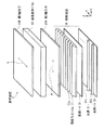
図1は、本発明の一実施の形態に係る表示装置1の概略構成を表すものである。この表示装置1は、液晶表示パネル10と、この液晶表示パネル10を挟む第1偏光子20Aおよび第2偏光子20Bと、第1偏光子20Aの背後に配置された照明装置30と、液晶表示パネル10を駆動して映像を表示させるための駆動回路(図示せず)とを備えている。この表示装置1では、第2偏光子20Bの表面が観察者(図示せず)側に向けられている。
FIG. 1 shows a schematic configuration of a display device 1 according to an embodiment of the present invention. The display device 1 includes a liquid
液晶表示パネル10は、例えば、映像信号に応じて各画素が駆動される透過型の表示パネルであり、液晶層を一対の透明基板で挟み込んだ構造となっている。具体的には、観察者側から順に、透明基板と、カラーフィルタと、透明電極と、配向膜と、液晶層と、配向膜と、透明画素電極と、透明基板とを有している。
The liquid
ここで、透明基板は、一般に、可視光に対して透明な基板である。なお、照明装置30側の透明基板には、透明画素電極に電気的に接続された駆動素子としてのTFT(Thin Film Transistor;薄膜トランジスタ)および配線などを含むアクティブ型の駆動回路が形成されている。カラーフィルタは、照明装置30からの射出光を例えば、赤(R)、緑(G)および青(B)の三原色にそれぞれ色分離するためのカラーフィルタを配列して形成されている。透明電極は、例えばITO(Indium Tin Oxide;酸化インジウムスズ)からなり、共通の対向電極として機能する。配向膜は、例えばポリイミドなどの高分子材料からなり、液晶に対して配向処理を行う。液晶層は、例えばVA(Virtical Alignment)モード、TN(Twisted Nematic)モード、またはSTN(Super TwistedNematic)モードの液晶からなり、図示しない駆動回路からの印加電圧により、照明装置30からの射出光を各画素ごとに透過または遮断する機能を有している。透明画素電極は、例えばITOからなり、画素ごとの電極として機能する。 Here, the transparent substrate is generally a substrate transparent to visible light. Note that an active driving circuit including a TFT (Thin Film Transistor) as a driving element electrically connected to the transparent pixel electrode, wiring, and the like is formed on the transparent substrate on the lighting device 30 side. The color filter is formed by arranging color filters for separating light emitted from the illumination device 30 into, for example, three primary colors of red (R), green (G), and blue (B). The transparent electrode is made of, for example, ITO (Indium Tin Oxide) and functions as a common counter electrode. The alignment film is made of, for example, a polymer material such as polyimide, and performs an alignment process on the liquid crystal. The liquid crystal layer is made of, for example, liquid crystal in a VA (Virtical Alignment) mode, a TN (Twisted Nematic) mode, or an STN (Super Twisted Nematic) mode, and emits light emitted from the illumination device 30 according to an applied voltage from a drive circuit (not shown). Each pixel has a function of transmitting or blocking. The transparent pixel electrode is made of, for example, ITO and functions as an electrode for each pixel.
第1偏光子20Aは、液晶表示パネル10の光入射側に配置された偏光子であり、第2偏光子20Bは液晶表示パネル10の光射出側に配置された偏光子である。第1偏光子20Aおよび第2偏光子20Bは、光学シャッタの一種であり、ある一定の振動方向の光(偏光)のみを通過させるものである。第1偏光子20Aおよび第2偏光子20Bはそれぞれ、偏光軸が互いに90度異なるように配置されており、これにより照明装置30からの射出光が液晶層を介して透過し、あるいは遮断されるようになっている。
The
第1偏光子20Aの偏光軸a(透過軸)の向きは、後述の凸部33aの延在方向における輝度向上フィルム33の屈折率と、凸部33aの延在方向と直交する方向における輝度向上フィルム33の屈折率との大小関係によって決定される。具体的には、偏光軸aと平行な方向の輝度向上フィルム33の屈折率が偏光軸aと直交する方向における輝度向上フィルム33の屈折率よりも小さくなるように、第1偏光子20Aの偏光軸aの向きが設定されている。
The direction of the polarization axis a (transmission axis) of the
本実施の形態では、後述するように、凸部33aの延在方向における輝度向上フィルム33の屈折率の方が凸部33aの延在方向と直交する方向における輝度向上フィルム33の屈折率よりも小さくなっている。従って、第1偏光子20Aの偏光軸aは、凸部33aの延在方向と平行な方向に向いている。ここで、「平行な方向に向いている」とは、凸部33aの延在方向だけでなく、凸部33aの延在方向と0度より大きく45度より小さな範囲内で交差する方向も含む概念である。なお、図1に示したように、偏光軸aが凸部33aの延在方向と平行となっていることが好ましい。ただし、適当な角度輝度分布を得ることや液晶表示パネル10のコントラストを向上させる等の他の理由により、偏光軸aと凸部33aの延在方向の向きとを一致させられないときには、偏光軸aと凸部33aの延在方向との成す角度を広げてもよい。この場合、正面輝度の向上のためにはこの角度を0度より大きく45度より小さくする必要があり、より好ましくは0度より大きく20度より小さくすることが望ましい。
In the present embodiment, as will be described later, the refractive index of the
なお、本実施の形態において、輝度向上フィルム33が本発明の「光学フィルム」の一具体例に相当し、凸部33aが本発明の「立体構造」の一具体例に相当する。
In the present embodiment, the
照明装置30は、光源31を有している。この照明装置30では、例えば、光源31の液晶表示パネル10側に、拡散シート32と、輝度向上フィルム33とが光源31側から順に配置されており、他方、光源31の背後に、反射シート34が配置されている。このように、本実施の形態では、照明装置30はいわゆる直下型となっているが、例えば、導光板を使用するサイドエッジ型となっていてもよい。
The illumination device 30 has a
光源31は、例えば、複数の線状光源31aが等間隔(例えば20mm間隔)で並列配置されたものである。線状光源31aは、例えば、熱陰極管(HCFL;Hot Cathode Fluorescent Lamp)または冷陰極管(CCFL;Cold Cathode Fluorescent Lamp)などが挙げられる。なお、光源31は、例えば発光ダイオード(LED;Light Emitting Diode)などの点光源を2次元配列したものであってもよいし、有機EL(Electro Luminescence)などの面光源であってもよい。
In the
反射シート34は、例えば、発泡PET(ポリエチレンテレフタレート)や銀蒸着フィルム、多層膜反射フィルムなどであり、光源31からの射出光の一部を、液晶表示パネル10の方向へ反射するようになっている。これにより、光源31からの射出光を効率的に利用することができる。
The
拡散シート32は、例えば、比較的厚手の板状の透明樹脂の内部に拡散材(フィラ)を分散して形成された拡散板、比較的薄手のフィルム状の透明樹脂上に拡散材を含む透明樹脂(バインダ)を塗布して形成された拡散フィルム、またはこれらを組み合わせたものである。板状またはフィルム状の透明樹脂には、例えばPET、アクリル、ポリカーボネートなどが用いられる。拡散材には、例えば、SiO2などの無機フィラや、アクリルなどの有機フィラなどが用いられる。
The
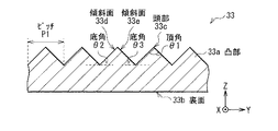
輝度向上フィルム33は、当該輝度向上フィルム33を含む面が液晶表示パネル10の表面と平行となるように配置されている。この輝度向上フィルム33の光射出側の面(表面)には、図1、図2に示したように、複数の柱状の凸部33a(立体構造)が、光射出側の面内において、水平方向(X軸方向)に向けて延在すると共に、延在方向と交差する方向に連続的に並列配置されている。なお、図2は、輝度向上フィルム33の断面の一例を拡大して表したものである。ここで、「水平方向に向けて」とは、水平方向だけでなく、水平面と0度より大きく45度より小さな範囲内で交差する方向も含む概念である。なお、図1、図2に示したように、各凸部33aが水平方向に延在すると共に延在方向と直交する方向(垂直方向、Y軸方向)に連続的に並列配置されていることが好ましい。他方、この輝度向上フィルム33の光入射側の面(裏面33b)は、例えば、平面となっている。なお、輝度向上フィルム33の裏面に、例えば2次元配列された凸部(シボ)が形成されていてもよい。
The
各凸部33aは、例えば、図2に示したように、頂角θ1の頭部33cに接する傾斜面33d,33eを有する三角柱形状となっており、これら傾斜面33d,33eは、当該輝度向上フィルム33を含む面に対して底角θ2,θ3で斜めに対向して配置されている。各凸部33aの配列方向の幅(ピッチP1)は、例えば10μm以上350μm以下となっている。なお、各凸部33aは、図2に示したような三角柱形状に限定されるものではなく、例えば、五角柱形状などの多角柱形状であってもよいし、各凸部33aの延在方向と直交する方向に、楕円形状および非球面形状などの曲面形状(例えばシリンドリカル形状)を有するものであってもよい。
The
また、各凸部33aが互いに同一の形状および同一の大きさになっていなくてもよい。例えば、(ア)隣接する同一形状の2つの凸部33aの一方が高く(大きく)、他方が低い(小さい)一組の立体構造を配列方向に等ピッチで並べて配置してもよいし、例えば、(イ)隣接する同一高さの2つの凸部33aの形状が互いに異なる一組の立体構造を配列方向に等ピッチで並べて配置してもよいし、例えば、(ウ)隣接する2つの凸部33aの形状および大きさ(高さ)の双方が互いに異なる一組の立体構造を配列方向に等ピッチで並べて配置してもよい。なお、各凸部33aの延在方向に複数の凸部や凹部を設けてもよい。
Moreover, each
これにより、各凸部33aは、輝度向上フィルム33の裏面33b側から入射した光のうち各凸部33aの配列方向の成分を液晶表示パネル10と直交する方向に向けて屈折透過させ、指向性を増加させるようになっている。なお、各凸部33aでは、輝度向上フィルム33の裏面33b側から入射した光のうち各凸部33aの延在方向の成分については各凸部33aの屈折作用による集光効果が少ない。
Thereby, each
ところで、本実施の形態では、各凸部33aは、各凸部33aの延在方向の屈折率が各凸部33aの配列方向の屈折率よりも小さい屈折率異方性を有している。ここで、上述したように、第1偏光子20Aの偏光軸aが凸部33aの延在方向と平行な方向に向いていることから、各凸部33aにおいて、偏光軸aと平行な方向の屈折率が偏光軸aと直交する方向の屈折率よりも小さくなっている。
By the way, in this Embodiment, each
このように、本実施の形態では、各凸部33aは、偏光軸aと平行な方向の屈折率が偏光軸aと直交する方向の屈折率よりも小さくなるような屈折率異方性を面内に持っている。これにより、偏光軸aと直交する方向についてより多く反射し、戻り光のリサイクルを行うことにより偏光軸aと平行な方向の光を増加させることができる。従って、輝度向上フィルム33へ入射する光の透過特性を偏光状態に応じて変えることができる。なお、各凸部33aが光射出側(表面)に設けられているときの方が光入射側(裏面)に設けられているときよりも臨界角の関係からリサイクル効率がよい。
Thus, in the present embodiment, each
ここで、屈折率の面内異方性は、半結晶性または結晶性の樹脂を含むシートを一の方向に延伸することにより発現させることが可能ではあるが、本実施の形態では、後述の製造方法を用いることにより、延伸を用いないで屈折率の面内異方性を発現させている。延伸しなくても屈折率の面内異方性を発現する材料としては、例えば、配向性を有する液晶性高分子が挙げられる。 Here, the in-plane anisotropy of the refractive index can be expressed by stretching a sheet containing a semi-crystalline or crystalline resin in one direction. By using the manufacturing method, in-plane anisotropy of the refractive index is expressed without using stretching. Examples of the material that exhibits in-plane anisotropy of refractive index without stretching include a liquid crystalline polymer having orientation.
ここで、液晶性高分子とは、液晶を形成した高分子であり、液晶高分子、高分子液晶などとも称されるものである。この液晶性高分子は、主鎖型、側鎖型、複合型という3種類の構造に分類可能である。ここで、主鎖型とは、液晶性を発現する部位を主鎖に備えたものであり、側鎖型とは、液晶性を発現する部位を側鎖に備えたものであり、複合型とは、液晶性を発現する部位を主鎖および側鎖の双方に備えたものである。また、液晶性高分子は、上記した分類方法の他に、サーモトロピック(熱溶融型)、リオトロピック(溶液型)という2つの型に分類することも可能である。ここで、熱溶融型とは、加熱溶融することによって、液晶状態になるものであり、熱溶融型の1つとして液晶ポリマー(LCP)を挙げることができる。また、溶液型とは、溶液状態にすることによって、液晶状態になるものである。 Here, the liquid crystalline polymer is a polymer that forms a liquid crystal, and is also referred to as a liquid crystal polymer, a polymer liquid crystal, or the like. This liquid crystalline polymer can be classified into three types of structures: main chain type, side chain type, and composite type. Here, the main chain type is a part having liquid crystallinity in the main chain, and the side chain type is a part having liquid crystallinity in the side chain, Is provided with a portion exhibiting liquid crystallinity in both the main chain and the side chain. In addition to the above classification method, the liquid crystalline polymer can also be classified into two types, thermotropic (thermal melting type) and lyotropic (solution type). Here, the heat melting type means a liquid crystal state when heated and melted, and a liquid crystal polymer (LCP) can be mentioned as one of the heat melting types. The solution type is a liquid crystal state when it is in a solution state.
この液晶性高分子は、例えば、ロッド状の液晶性モノマと光重合開始剤とを含む組成物に対して紫外線を照射して、ロッド状の液晶性モノマを重合させることにより形成することが可能な材料である。 This liquid crystalline polymer can be formed, for example, by irradiating a composition containing a rod-shaped liquid crystalline monomer and a photopolymerization initiator with ultraviolet rays to polymerize the rod-shaped liquid crystalline monomer. Material.
次に、輝度向上フィルム33全体の屈折率が各凸部33aの延在方向と、各凸部33aの配列方向とで異なる場合における輝度向上フィルム33の機能について説明する。
Next, the function of the
図3は、輝度向上フィルム33全体が、各凸部33aの延在方向の屈折率nxが各凸部33aの配列方向の屈折率nyよりも小さい(nx<ny)材料により構成されている場合に、輝度向上フィルム33の裏面から照明装置30の光が入射したときの光の経路の一例を示したものである。なお、図3において、Lxは、照明装置30の光のうち各凸部33aの延在方向(X方向)に振動する偏光成分を示し、Lyは、照明装置30の光のうち各凸部33aの配列方向(Y方向)に振動する偏光成分を示している。
FIG. 3 shows a case where the entire
輝度向上フィルム33を含む面に対して斜め方向から入射した照明装置30の光は、図3の左側に示したように、輝度向上フィルム33の裏面で、照明装置30の光のX方向偏光成分LxとY方向偏光成分Lyとにおいて異なる屈折角rx,ry(rx<ry)でそれぞれ屈折するとともに、異なる射出角φx,φy(φx<φy)で輝度向上フィルム33の表面(各凸部33aの光射出面)から射出する。
The light of the illumination device 30 incident from an oblique direction with respect to the surface including the
このとき、輝度向上フィルム33は各凸部33aの延在方向と各凸部33aの配列方向とで異なる屈折率(nx<ny)を有しているので、これら各方向に振動する偏光成分は、輝度向上フィルム33の裏面および凸部33aの光射出面といった界面において、互いに異なる反射率で反射される。従って、Lyの反射量がLxの反射量よりも大きくなる。そのため、輝度向上フィルム33を透過した光において、Lxの光量の方がLyの光量よりも多くなる。
At this time, since the
また、輝度向上フィルム33は各凸部33aの延在方向と各凸部33aの配列方向とで異なる屈折率(nx<ny)を有しているので、これらの各方向に振動する偏光成分は、輝度向上フィルム33の裏面および凸部33aの光入射面といった界面において、互いに異なる臨界角を有する。従って、ある入射角で入射した光は光射出面において、その射出面に入る角度がLyの臨界角よりも大きく、Lxの臨界角よりも小さいときには、図3の中央に示したように、Lyは全反射し、Lxは透過する。よって、偏光成分Lyが各凸部33aの光射出面で全反射を繰り返して戻り光となり、偏光成分Lxのみが各凸部33aの光射出面を透過する完全な偏光分離状態を実現することができる。
In addition, since the
また、各凸部33aの光射出面に対する照明装置30の光の入射角が大きくなり過ぎると、図3の右側に示したように、照明装置30の光は偏光状態に関係なく、各凸部33aの光射出面において全反射を繰り返して、照明装置30側へ戻る戻り光となる。
Further, when the incident angle of the light of the illumination device 30 with respect to the light exit surface of each
ここで、輝度向上フィルム33の表面または裏面で反射された光は、照明装置30の反射シート34(図1)や拡散シート32の表面において反射し無偏光化されて再び輝度向上フィルム33へ入射する。これにより、一方の偏光成分(Lx)の光量を他方の偏光成分(Ly)の光量よりも格段に多くすることが可能となる。その結果、各凸部33aが偏光分離作用を有していない場合よりも、光の利用効率が高まり正面輝度が向上する。
Here, the light reflected on the front surface or the back surface of the
なお、光透過フィルム(図示せず)の上に、輝度向上フィルム33を裏面33b側から張り合わせた場合や、輝度向上フィルム33の凸部33aだけが面内に屈折率異方性を有している場合には、光透過フィルムとの接触面や、凸部33bの底部が、輝度向上フィルム33全体が屈折率異方性を有している場合における裏面33bとして機能する。従って、輝度向上フィルム33を裏面33b側から張り合わせた場合や、輝度向上フィルム33の凸部33aだけが屈折率異方性を有している場合にも、輝度向上フィルム33全体に面内の屈折率異方性をもたせた場合と同様の光学的な機能を発揮する。
In addition, when the
このように、輝度向上フィルム33は、集光作用に加え、偏光分離作用によって正面輝度を向上させるようになっている。
Thus, the
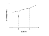
次に、図4(A)〜(B)、図5(A)〜(B)、図6、図7(A)〜(C)および図8を参照して、輝度向上フィルム33の形成方法の一例について説明する。なお、図4(A)〜(B)、図5(A)〜(B)、図7(A)〜(B)は、輝度向上フィルム33の形成過程を説明するための断面構成を表したものである。図6は、図5(B)の工程を斜視的に表したものである。図8は、ロッド状の液晶性モノマのDSC曲線の一例を表したものである。なお、図8において、T1は液晶相への相転移温度(融点)であり、T2は等方相への相転移温度である。
Next, with reference to FIG. 4 (A)-(B), FIG. 5 (A)-(B), FIG. 6, FIG. 7 (A)-(C) and FIG. An example will be described. 4 (A) to (B), FIGS. 5 (A) to (B), and FIGS. 7 (A) to (B) represent cross-sectional configurations for explaining the formation process of the
まず、一の面内に連続して配置され、かつ一の面内において形状異方性を有する複数の凸部100aを有する原盤100を用意する(図4(A)参照)。この原盤100の複数の凸部100aによって形成される凹凸形状は、輝度向上フィルム33上に2次元配置された複数の凸部33aによって形成される凹凸形状と反対の凹凸形状となっている。この凹凸形状の表面には、例えば、シリコン系やフッ素系の離形剤が塗布されていることが好ましい。また、ロッド状の液晶性モノマと光重合開始剤とを混合した組成物110(液晶調整粉)を用意する。
First, a
次に、原盤100をホットプレート120上に配置して、組成物110に含まれるロッド状の液晶性モノマの融点T1(図8参照)以上の温度で加熱したのち、原盤100の凸部100a上に組成物110(液晶調整粉)を落とす(図4(B))。すると、組成物110が溶解すると共に、組成物110の粘性が低下して組成物110が凸部100aに隙間無く接する。
Next, the
次に、ホットプレート120の温度を、融点T1以上の温度を保った状態で、光透過フィルム130を、組成物110上に乗せる(図5(A))。なお、光透過フィルム130のうち組成物110と接する表面に、ロッド状の液晶性モノマを凸部100aの配列方向に配向させる配向膜が設けられていることが好ましい。
Next, the
このようにして、原盤100と、原盤100の凸部100aと対向配置された光透過フィルム130との間に、組成物110を保持した状態で、この組成物110を、融点T1以上の温度であって、かつ相転移温度T2以下の温度で加熱すると共に押圧する。具体的には、図5(B)に示したように、押圧ローラ140を光透過フィルム130上で、凸部100aの配列方向に転がしつつ、光透過フィルム130を介して組成物110を原盤100の凸部100aに押し当てる。これにより、組成物110が押圧によって、互いに隣り合う凸部100aおよび凸部100aの間の谷部の中で、凸部100aの配列方向に向かって押し動かされる。その結果、組成物110が、図6に示したように、凸部100aの配列方向に液晶配向し、さらに、図5(B)に示したように、組成物110に、高さH1の凸部110aと、厚さH2の袴110bとを有する光学機能層が形成される。
In this manner, the
なお、凸部100aの表面に上記離形剤が塗布されている場合には、この離形剤によるアンカー効果によってロッド状の液晶性モノマが凸部100aの配列方向に配向するのを促進することが可能である。また、光透過フィルム130のうち組成物110と接する表面に上記配向膜が設けられている場合にも、ロッド状の液晶性モノマを凸部100aの配列方向に配向するのを促進することが可能である。
In addition, when the said mold release agent is apply | coated to the surface of the
その後、ホットプレート120を原盤100から取り外し、放置しながら、常温まで空冷する(図7(A))。次に、組成物110に対して紫外線Lを照射する。例えば、図7(B)に示したように、光透過フィルム130側から組成物110に対して紫外線Lを照射して、組成物110に含まれるロッド状の液晶性モノマを光透過フィルム130側から重合する。これにより、ロッド状の液晶性モノマが凸部100aの配列方向に配向性を有する液晶性高分子となる。最後に、光透過フィルム130を原盤100から剥離する(図7(C))。このようにして、配向性を有する液晶性高分子を含む組成物110と、光透過フィルム130とを備えた輝度向上フィルム33が形成される。
Thereafter, the
なお、輝度向上フィルム33は、例えば、以下に示した方法でも形成することが可能である。
Note that the
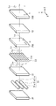
図9は輝度向上フィルム33の製造装置の一例を表したものである。この製造装置は、巻き出しロール200と、ガイドロール210,260,270と、ヒートロール220,230と、温調ロール240(押圧ローラ)と、温調ロール250と、吐出機300と、紫外線照射機310とを備えたものである。ここで、巻き出しロール200は、光透過フィルム130を同心円状に巻いたものであり、光透過フィルム130を供給するためものである。巻き出しロール200から巻き出された光透過フィルム130は、ガイドロール210、ヒートロール220、ヒートロール230、温調ロール240、ガイドロール260、ガイドロール270の順に流れて行き、最後に巻き取りロール280で巻き取られるようになっている。温調ロール250は、ヒートロール230,240と所定の間隙を介して配置されている。吐出機は、巻き出しロール200から供給された光透過フィルム130のうちヒートロール220と接する部分と所定の間隙を介して吐出機300が設けられている。紫外線照射機310は、巻き出しロール200から供給された光透過フィルム130のうちヒートロール240を通過した後の部分であって、かつ温調ロール250と接している部分に対して紫外線を照射するようになっている。
FIG. 9 shows an example of an apparatus for manufacturing the
ガイドロール210は、巻き出しロール200から供給された光透過フィルム130をヒートロール220に導くためのものである。ヒートロール220は、常温から200℃程度まで発熱可能なものであり、例えば融点T1以上の温度の発熱温度に設定されている。巻き出しロール200から供給された光透過フィルム130のうちヒートロール220と接する部分と所定の間隙を介して吐出機300が設けられている。この吐出機300は、ロッド状の液晶性モノマを熱溶解させたものに光重合開始剤を混合した組成物110を融点T1以上の温度で加熱しつつ、光透過フィルム130上に滴下するためものである。ヒートロール230は、常温から200℃程度まで発熱可能なものであり、例えば、融点T1以上の温度に設定されている。温調ロール240,250は、常温から90℃程度まで温度調節可能なものであり、例えば、相転移温度T2よりも低い温度(常温)の冷却温度に設定されている。また、温調ロール250の周面には、温調ロール250の回転軸と平行な方向に延在すると共に温調ロール250の回転軸と直交する方向に連続して並列配置された複数の凸部が形成されている。周面に形成された複数の凸部によって形成される凹凸形状は、輝度向上フィルム33上に2次元配置された複数の凸部33aによって形成される凹凸形状と反対の凹凸形状となっている。ガイドロール260は、温調ロール250に巻きついている光透過フィルム130を剥がすためのものである。また、ガイドロール270は、ガイドロール260によって剥がされた光透過フィルム130を巻き取りロール280に導くためのものである。
The
このような構成の製造装置を用いて、輝度向上フィルム33を形成する。具体的には、まず、巻き出しロール200から巻き出した光透過フィルム130を、ガイドロール210を介してヒートロール220に導いたのち、光透過フィルム130上に、ロッド状の液晶性モノマを熱溶解させたものに光重合開始剤を混合した組成物110を、吐出機300から滴下する。吐出機300から滴下された組成物110をヒートロール220で、融点T1(図8参照)以上の温度に加熱したのち、ヒートロール230によって、光透過フィルム130上の組成物110の温度を、融点T1以上の温度で維持しつつ、組成物110を温調ロール250の周面に形成された凸部に押し当てる。これにより、組成物110が温調ロール250の凸部に隙間無く接すると共に、組成物110が押圧によって、互いに隣り合う凸部同士の間の谷部の中で、凸部の配列方向に向かって押し動かされる。その結果、組成物110は、温調ロール250の凸部の配列方向に液晶配向し、さらに、組成物110に、高さH1の凸部110aと、厚さH2の袴110bとを有する光学機能層が形成される。
The
その後、温調ロール240,250で、組成物110を相転移温度T2よりも低い温度に冷却して、紫外線照射機310から、冷却された組成物110に対して紫外線Lを照射する。これにより、組成物110に含まれるロッド状の液晶性モノマが光透過フィルム130側から重合するので、ロッド状の液晶性モノマが温調ロール250の凸部の配列方向に配向性を有する液晶性高分子となる。最後に、ガイドロール260で、光透過フィルム130を温調ロール250から剥離したのち、ガイドロール270を介して巻き取りロール280に巻き取る。このようにして、配向性を有する液晶性高分子を含む組成物110と、光透過フィルム130とを備えた輝度向上フィルム33が形成される。
Thereafter, the
なお、輝度向上フィルム33を上記各製造方法で製造した場合には、袴110bの厚さH2は、凸部110aの高さH1の40%以下となっていることが好ましい。
In the case where the
次に、本実施の形態の表示装置1において画像を表示する際の作用について、図10を参照しつつ説明する。なお、図10は、表示装置1の作用の一例を模式的に表したものである。 Next, the operation when displaying an image in the display device 1 of the present embodiment will be described with reference to FIG. FIG. 10 schematically illustrates an example of the operation of the display device 1.
光源31から照射され拡散シート32を透過した無偏光の光Lは、輝度向上フィルム33の裏面に入射し、凸部33aの集光作用によって指向性を高める。また、このとき、光Lは、凸部33aの偏光分離作用によって第1偏光子20Aの偏光軸aと平行な偏光成分(Lx)と、第1偏光子20Aの偏光軸aと直交する偏光成分(Ly)とに分離されたのち、主に、偏光軸aと平行な偏光成分(Lx)が第1偏光子20Aへ入射する。
The non-polarized light L emitted from the
第1偏光子20Aへ入射した光Lのうち、偏光軸aと交差する偏光成分(Ly)が第1偏光子20Aで吸収され、偏光軸aと平行な偏光成分(Lx)が第1偏光子20Aを透過する。第1偏光子20Aを透過したLxは、液晶表示パネル10において画素単位で偏光制御がなされて第2偏光子20Bへ入射し、第2偏光子12Bの偏光軸bの偏光のみが透過してパネル正面に画像を形成する。このようにして、表示装置1において画像が表示される。
Of the light L incident on the
ところで、本実施の形態では、輝度向上フィルム33の一の面内において形状異方性を有する凸部33aが、上記一の面内において配向性を有する液晶性高分子を含んで構成されており、この液晶性高分子の配向性に応じた屈折率異方性を有している。ここで、配向性を有する液晶性高分子は、例えば、上記したような方法により形成可能なものである。また、延伸により液晶性高分子に配向性を持たせることはできないことから、本実施の形態の輝度向上フィルム33は延伸を用いて形成することができず、上記で例示した方法で形成可能と言える。これにより、輝度向上フィルム33の凸部33aには延伸による形状の崩れがないので、形状の崩れがほとんどない、屈折率異方性を有する凸部33aを備えた輝度向上フィルム33を実現することができる。
By the way, in the present embodiment, the
また、本実施の形態の輝度向上フィルム33の製造方法では、ロッド状の液晶性モノマと光重合開始剤とを含む組成物110に対して、上記した加熱、押圧、冷却および紫外線照射の各処理を順に行うことにより、輝度向上フィルム33の凸部33aに屈折率異方性を発現させるようにしたので、延伸を用いなくても、輝度向上フィルム33の凸部33aに屈折率異方性を付与することができる。これにより、屈折率異方性を有する凸部33aを精確に形成することができる。
Moreover, in the manufacturing method of the
[実施例]
次に、上記実施の形態の輝度向上フィルム33の実施例1,2について比較例1,2,3と対比して説明する。実施例1,2および比較例2,3では、製造過程で用いられる組成物110にロッド状の液晶性モノマを含ませた。実施例1、比較例2ではロッド状の液晶性モノマとして高Δnタイプを使用し、実施例2、比較例3ではロッド状の液晶性モノマとして低Δnタイプを使用した。比較例1では、ロッド状の液晶性モノマの代わりに光硬化アクリルモノマを組成物110に含ませた。また、実施例および比較例1では、製造過程における押圧の方向を原盤100の凸部100a(または温調ロール250の凸部)の配列方向にし、比較例2では、製造過程における押圧の方向を原盤100の凸部100a(または温調ロール250の凸部)の延在方向にした。
[Example]
Next, Examples 1 and 2 of the
実施例および比較例1,2において、輝度向上フィルムの凸部の形状を直角二等辺三角柱とし、輝度向上フィルムの凸部の幅を25μm、高さを12.5μmとした。また、光透過フィルム130としてPETフィルムを用いた。
In Examples and Comparative Examples 1 and 2, the shape of the convex portion of the brightness enhancement film was a right isosceles triangular prism, the width of the convex portion of the brightness enhancement film was 25 μm, and the height was 12.5 μm. A PET film was used as the
具体的な製造方法について、実施例2を例に挙げて説明する。まず、市販の液晶性モノマ溶液(RMS03−001c、重合開始剤入り、等方相への相転移温度:70℃、メルク株式会社製)を、まずホットプレート上で150℃、1分加熱し、溶媒を蒸発させた後、ホットプレート上に残った組成物(液晶性モノマと重合開始剤との混合液)を、等方相への相転移温度以下(50℃)のホットプレートで加熱しているNi電鋳プリズム原盤(頂角90度の二等辺三角形、25μmピッチ、高さ12.5μm)上に移した。次に、ホットプレートの温度を50℃に保持したまま、Ni電鋳プリズム原盤上の組成物をPETフィルムにて封止した後、PETフィルム上でローラをプリズムの配列方向に転がしつつ、PETフィルム上にローラを強く押し当てることにより組成物の厚みを薄く均一化した。その後、ホットプレートをNi電鋳プリズム原盤から取り外し、Ni電鋳プリズム原盤上の組成物を放置しながら常温まで空冷させた。その後、PETフィルム側から組成物に向けてUV照射を行うことにより組成物内の液晶性モノマを重合させたのち、Ni電鋳プリズム原盤から組成物を剥離することにより実施例2の光透過フィルムを得た。 A specific manufacturing method will be described using Example 2 as an example. First, a commercially available liquid crystalline monomer solution (RMS 03-001c, containing a polymerization initiator, phase transition temperature to isotropic phase: 70 ° C., manufactured by Merck Ltd.) was first heated on a hot plate at 150 ° C. for 1 minute, After evaporating the solvent, the composition (mixed liquid crystal monomer and polymerization initiator) remaining on the hot plate is heated on a hot plate having a temperature lower than the phase transition temperature to the isotropic phase (50 ° C.). It was transferred onto a Ni electroformed prism master (an isosceles triangle with an apex angle of 90 degrees, a pitch of 25 μm, a height of 12.5 μm). Next, the composition on the Ni electroformed prism master is sealed with a PET film while maintaining the temperature of the hot plate at 50 ° C., and then the PET film is rolled on the PET film while rolling the roller in the prism arrangement direction. The thickness of the composition was made thin and uniform by strongly pressing the roller on top. Thereafter, the hot plate was removed from the Ni electroformed prism master and allowed to cool to room temperature while leaving the composition on the Ni electroformed prism master. Thereafter, the liquid crystal monomer in the composition was polymerized by performing UV irradiation from the PET film side toward the composition, and then the composition was peeled off from the Ni electroformed prism original disk, whereby the light transmitting film of Example 2 was used. Got.
[断面形状]
輝度向上フィルムの配列方向の断面を走査型共焦点レーザ顕微鏡(LEXT OLS3000、オリンパス(株)製)で測定した。その結果、実施例1,2および比較例1,2,3において、輝度向上フィルムの断面はそれぞれ、原盤100の凹凸形状と同じ頂角90度、底角45度の直角二等辺三角形となっていた。このことから、輝度向上フィルムの凸部には形状の崩れが無いことがわかった。
[Cross-sectional shape]
The cross section in the arrangement direction of the brightness enhancement film was measured with a scanning confocal laser microscope (LEXT OLS3000, manufactured by Olympus Corporation). As a result, in Examples 1 and 2 and Comparative Examples 1, 2 and 3, the cross sections of the brightness enhancement films are respectively right-angled isosceles triangles having an apex angle of 90 degrees and a base angle of 45 degrees as the concave and convex shape of the
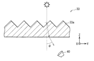
[複屈折性]
次に、輝度向上フィルムの複屈折性を測定した。複屈折性の測定には、図11に示すように、輝度向上フィルム33の凸部33a側から偏光を垂直に入射し、透過光を測定器40で検出し、透過光の出射角φの違いにより、凸部33aの延在方向の屈折率nxと配列方向の屈折率nyとの差Δn(=nx−ny)を算出した。なお、図12に示したように、凸部33aの延在方向に振動する偏光成分を垂直偏光Lxとし、凸部33aの配列方向に振動する偏光成分を水平偏光Lyとすると、垂直偏光Lxの射出角φxの方が水平偏光Lyの射出角φyよりも小さくなった。
[Birefringence]
Next, the birefringence of the brightness enhancement film was measured. In the birefringence measurement, as shown in FIG. 11, polarized light is vertically incident from the
測定の結果、実施例1において、輝度向上フィルムの延在方向の屈折率nxが1.54であり、配列方向の屈折率nyが1.87であったので、屈折率の差Δnは−0.33であった。また、実施例2においても、輝度向上フィルムの延在方向の屈折率nxが1.55であり、配列方向の屈折率nyが1.70であったので、屈折率の差Δnは−0.15であった。これらのことから、ロッド状の液晶性モノマを用いることにより、輝度向上フィルムの延在方向の屈折率nxが配列方向の屈折率nyよりも低い屈折率異方性を発現させることができることがわかった。一方、比較例1においては、輝度向上フィルムの延在方向の屈折率nxが1.59であり、配列方向の屈折率nyが1.59であったので、屈折率の差Δnは0.00であった。このことから、光硬化アクリルモノマを用いた場合には、屈折率異方性を発現させることができないことがわかった。また、比較例2においては、輝度向上フィルムの延在方向の屈折率nxが1.87であり、配列方向の屈折率nyが1.54であったので、屈折率の差Δnは+0.33であった。さらに、比較例3においても、輝度向上フィルムの延在方向の屈折率nxが1.70であり、配列方向の屈折率nyが1.55であったので、屈折率の差Δnは+0.15であった。これらのことから、光硬化アクリルモノマを用いた場合であっても、製造過程における押圧の方向を原盤100の凸部100a(または温調ロール250の凸部)の延在方向としたときには、輝度向上フィルムの延在方向の屈折率nxが配列方向の屈折率nyよりも低い屈折率異方性を発現させることができないことがわかった。
As a result of the measurement, in Example 1, since the refractive index nx in the extending direction of the brightness enhancement film was 1.54 and the refractive index ny in the arrangement direction was 1.87, the refractive index difference Δn was −0. .33. Also in Example 2, since the refractive index nx in the extending direction of the brightness enhancement film was 1.55 and the refractive index ny in the arrangement direction was 1.70, the refractive index difference Δn was −0. It was 15. From these facts, it is understood that the refractive index anisotropy in which the refractive index nx in the extending direction of the brightness enhancement film is lower than the refractive index ny in the arrangement direction can be exhibited by using a rod-like liquid crystalline monomer. It was. On the other hand, in Comparative Example 1, since the refractive index nx in the extending direction of the brightness enhancement film was 1.59 and the refractive index ny in the arrangement direction was 1.59, the refractive index difference Δn was 0.00 Met. From this, it was found that the refractive index anisotropy cannot be exhibited when using a photo-curing acrylic monomer. In Comparative Example 2, since the refractive index nx in the extending direction of the brightness enhancement film was 1.87 and the refractive index ny in the arrangement direction was 1.54, the refractive index difference Δn was +0.33. Met. Furthermore, also in Comparative Example 3, since the refractive index nx in the extending direction of the brightness enhancement film was 1.70 and the refractive index ny in the arrangement direction was 1.55, the refractive index difference Δn was +0.15. Met. For these reasons, even when a photo-curing acrylic monomer is used, when the pressing direction in the manufacturing process is the extending direction of the
以上、実施の形態および実施例を挙げて本発明を説明したが、本発明はこれらの実施の形態等に限定されるものではなく、種々の変形が可能である。 Although the present invention has been described with reference to the embodiments and examples, the present invention is not limited to these embodiments and the like, and various modifications are possible.
また、上記実施の形態等では、液晶表示装置の構成を具体的に挙げて説明したが、全ての層を備える必要はなく、また、他の層を備えていてもよい。 In the above-described embodiments and the like, the configuration of the liquid crystal display device has been specifically described, but it is not necessary to provide all layers, and other layers may be provided.
1…表示装置、10…液晶表示パネル、20A…第1偏光子、20B……第2偏光子、30…照明装置、31…光源、31a…線状光源、32…拡散シート、33…輝度向上フィルム、33a…凸部、34…反射シート。 DESCRIPTION OF SYMBOLS 1 ... Display apparatus, 10 ... Liquid crystal display panel, 20A ... 1st polarizer, 20B ... 2nd polarizer, 30 ... Illumination device, 31 ... Light source, 31a ... Linear light source, 32 ... Diffusing sheet, 33 ... Brightness improvement Film, 33a ... convex part, 34 ... reflective sheet.
Claims (7)
前記立体構造は、配向性を有する液晶性高分子を含み、かつ当該立体構造の延在方向の屈折率が当該立体構造の延在方向と交差する方向の屈折率よりも小さな屈折率異方性を有する光学フィルム。 A plurality of three-dimensional structures extending in one direction and continuously arranged in a direction intersecting with the one direction;
The three-dimensional structure includes a liquid crystalline polymer having orientation, and the refractive index anisotropy in which the refractive index in the extending direction of the three-dimensional structure is smaller than the refractive index in the direction intersecting the extending direction of the three-dimensional structure. An optical film having
前記光透過フィルム上に形成された光学機能層と
を備え、
前記立体構造は、前記光学機能層のうち前記光透過フィルムとは反対側の表面に形成され、
前記光学機能層のうち前記立体構造と前記光透過フィルムとの間の部分の厚さは、前記立体構造の高さの40%以下となっている請求項1に記載の光学フィルム。 A light transmissive film;
An optical functional layer formed on the light transmissive film,
The three-dimensional structure is formed on the surface of the optical functional layer opposite to the light transmission film,
2. The optical film according to claim 1, wherein a thickness of a portion between the three-dimensional structure and the light transmission film in the optical functional layer is 40% or less of a height of the three-dimensional structure.
前記組成物を常温まで冷やしたのち、前記組成物に対して紫外線を照射して、前記ロッド状の液晶性モノマを重合させ、前記光透過フィルムを前記原盤から剥離する第2工程と
を含む光学フィルムの製造方法。 Between a master that includes a plurality of three-dimensional structures that extend in one direction and that are continuously arranged in a direction that intersects the one direction, and a light-transmitting film that is disposed to face the three-dimensional structure of the master. The composition is heated at a temperature equal to or higher than the melting point of the rod-shaped liquid crystalline monomer while holding the composition containing the rod-shaped liquid crystalline monomer and a photopolymerization initiator, and the pressure roller is A first step of contacting the transmission film and pressing the composition by rolling in the direction of arrangement of the three-dimensional structure of the master,
An optical process comprising: cooling the composition to room temperature, irradiating the composition with ultraviolet light, polymerizing the rod-like liquid crystalline monomer, and peeling the light-transmitting film from the master. A method for producing a film.
前記表示パネルを挟む一対の偏光子と、
前記パネルを照明する光源と、
前記偏光子と光源との間に設けられた光学フィルムと
を備え、
前記光学フィルムは、
一の方向に延在すると共に前記一の方向と交差する方向に連続して配置された複数の立体構造を備え、
前記立体構造は、配向性を有する液晶性高分子を含み、かつ当該立体構造の延在方向の屈折率が当該立体構造の延在方向と交差する方向の屈折率よりも小さな屈折率異方性を有する表示装置。 A panel driven based on an image signal;
A pair of polarizers sandwiching the display panel;
A light source for illuminating the panel;
An optical film provided between the polarizer and the light source,
The optical film is
A plurality of three-dimensional structures extending in one direction and continuously arranged in a direction intersecting with the one direction;
The three-dimensional structure includes a liquid crystalline polymer having orientation, and the refractive index anisotropy in which the refractive index in the extending direction of the three-dimensional structure is smaller than the refractive index in the direction intersecting the extending direction of the three-dimensional structure. A display device.
ことを特徴とする請求項6に記載の表示装置。 The direction with the smallest refractive index in the three-dimensional structure is parallel to the direction of the light transmission axis of the polarizer on the light source side, or intersects within a range larger than 0 degree and smaller than 45 degrees. The display device according to claim 6.
Priority Applications (3)
| Application Number | Priority Date | Filing Date | Title |
|---|---|---|---|
| JP2008200671A JP5217747B2 (en) | 2008-08-04 | 2008-08-04 | Optical film, method for producing the same, and display device |
| CN2009101640220A CN101644851B (en) | 2008-08-04 | 2009-08-04 | Optical film, method of manufacturing the same, and display unit |
| US12/534,989 US8400578B2 (en) | 2008-08-04 | 2009-08-04 | Optical film, method of manufacturing the same, and display unit |
Applications Claiming Priority (1)
| Application Number | Priority Date | Filing Date | Title |
|---|---|---|---|
| JP2008200671A JP5217747B2 (en) | 2008-08-04 | 2008-08-04 | Optical film, method for producing the same, and display device |
Publications (2)
| Publication Number | Publication Date |
|---|---|
| JP2010039105A true JP2010039105A (en) | 2010-02-18 |
| JP5217747B2 JP5217747B2 (en) | 2013-06-19 |
Family
ID=41607809
Family Applications (1)
| Application Number | Title | Priority Date | Filing Date |
|---|---|---|---|
| JP2008200671A Expired - Fee Related JP5217747B2 (en) | 2008-08-04 | 2008-08-04 | Optical film, method for producing the same, and display device |
Country Status (3)
| Country | Link |
|---|---|
| US (1) | US8400578B2 (en) |
| JP (1) | JP5217747B2 (en) |
| CN (1) | CN101644851B (en) |
Cited By (1)
| Publication number | Priority date | Publication date | Assignee | Title |
|---|---|---|---|---|
| JP2013061518A (en) * | 2011-09-14 | 2013-04-04 | Dainippon Printing Co Ltd | Prism sheet mold manufacturing method and belt-like polarizer integrated prism sheet |
Families Citing this family (2)
| Publication number | Priority date | Publication date | Assignee | Title |
|---|---|---|---|---|
| JP5991053B2 (en) * | 2011-10-04 | 2016-09-14 | ソニー株式会社 | Display device and lighting device |
| CN108459439B (en) * | 2018-05-16 | 2023-11-17 | 京东方科技集团股份有限公司 | Backlight module and liquid crystal display device |
Citations (9)
| Publication number | Priority date | Publication date | Assignee | Title |
|---|---|---|---|---|
| JP2000221324A (en) * | 1999-02-03 | 2000-08-11 | Nec Corp | Polarizing device and liquid crystal display device having that polarizing device |
| JP2004037480A (en) * | 2002-06-28 | 2004-02-05 | Asahi Glass Co Ltd | Liquid crystal element and optical attenuator |
| JP2006119258A (en) * | 2004-10-20 | 2006-05-11 | Dainippon Printing Co Ltd | Authenticity determination object and authenticity determination label |
| JP2007041583A (en) * | 2005-07-30 | 2007-02-15 | Samsung Electronics Co Ltd | Polarization compensation film, manufacturing method of polarizing prism film, display panel assembly and display device |
| JP2007206104A (en) * | 2006-01-30 | 2007-08-16 | Fujifilm Corp | Polarization conversion film, method of manufacturing same, polarization element and liquid crystal display device |
| JP2007213057A (en) * | 2006-02-08 | 2007-08-23 | Samsung Electronics Co Ltd | Polarization light guide plate, method of manufacturing the same and illuminator for flat panel display device using the polarization light guide plate |
| JP2007256493A (en) * | 2006-03-22 | 2007-10-04 | Sony Corp | Optical sheet, method of manufacturing optical sheet, back light apparatus, and and liquid crystal display |
| JP2008525230A (en) * | 2004-12-23 | 2008-07-17 | スリーエム イノベイティブ プロパティズ カンパニー | Uniaxially oriented birefringent article having a structured surface |
| JP2009109840A (en) * | 2007-10-31 | 2009-05-21 | Sony Corp | Optical sheet, method of manufacturing the same and display apparatus |
Family Cites Families (6)
| Publication number | Priority date | Publication date | Assignee | Title |
|---|---|---|---|---|
| JPH01273002A (en) | 1988-04-26 | 1989-10-31 | Seiko Epson Corp | Birefringent lens array |
| JPH071428U (en) * | 1993-06-04 | 1995-01-10 | 株式会社エンプラス | Surface light source |
| JP2004198725A (en) * | 2002-12-18 | 2004-07-15 | Sumitomo Rubber Ind Ltd | Liquid crystal display, direct back light, and diffusing plate |
| CN100462750C (en) * | 2004-10-27 | 2009-02-18 | 柯尼卡美能达精密光学株式会社 | Phase aberration film production method and phase aberration film produced by the method,polarization sheet using same and liquid crystal display |
| US20060138702A1 (en) | 2004-12-23 | 2006-06-29 | Biernath Rolf W | Method of making uniaxially oriented articles having structured surfaces |
| JP4158824B2 (en) * | 2005-09-15 | 2008-10-01 | ソニー株式会社 | Light transmissive film, method for producing light transmissive film, and liquid crystal display device |
-
2008
- 2008-08-04 JP JP2008200671A patent/JP5217747B2/en not_active Expired - Fee Related
-
2009
- 2009-08-04 CN CN2009101640220A patent/CN101644851B/en not_active Expired - Fee Related
- 2009-08-04 US US12/534,989 patent/US8400578B2/en not_active Expired - Fee Related
Patent Citations (9)
| Publication number | Priority date | Publication date | Assignee | Title |
|---|---|---|---|---|
| JP2000221324A (en) * | 1999-02-03 | 2000-08-11 | Nec Corp | Polarizing device and liquid crystal display device having that polarizing device |
| JP2004037480A (en) * | 2002-06-28 | 2004-02-05 | Asahi Glass Co Ltd | Liquid crystal element and optical attenuator |
| JP2006119258A (en) * | 2004-10-20 | 2006-05-11 | Dainippon Printing Co Ltd | Authenticity determination object and authenticity determination label |
| JP2008525230A (en) * | 2004-12-23 | 2008-07-17 | スリーエム イノベイティブ プロパティズ カンパニー | Uniaxially oriented birefringent article having a structured surface |
| JP2007041583A (en) * | 2005-07-30 | 2007-02-15 | Samsung Electronics Co Ltd | Polarization compensation film, manufacturing method of polarizing prism film, display panel assembly and display device |
| JP2007206104A (en) * | 2006-01-30 | 2007-08-16 | Fujifilm Corp | Polarization conversion film, method of manufacturing same, polarization element and liquid crystal display device |
| JP2007213057A (en) * | 2006-02-08 | 2007-08-23 | Samsung Electronics Co Ltd | Polarization light guide plate, method of manufacturing the same and illuminator for flat panel display device using the polarization light guide plate |
| JP2007256493A (en) * | 2006-03-22 | 2007-10-04 | Sony Corp | Optical sheet, method of manufacturing optical sheet, back light apparatus, and and liquid crystal display |
| JP2009109840A (en) * | 2007-10-31 | 2009-05-21 | Sony Corp | Optical sheet, method of manufacturing the same and display apparatus |
Cited By (1)
| Publication number | Priority date | Publication date | Assignee | Title |
|---|---|---|---|---|
| JP2013061518A (en) * | 2011-09-14 | 2013-04-04 | Dainippon Printing Co Ltd | Prism sheet mold manufacturing method and belt-like polarizer integrated prism sheet |
Also Published As
| Publication number | Publication date |
|---|---|
| CN101644851A (en) | 2010-02-10 |
| CN101644851B (en) | 2012-02-22 |
| JP5217747B2 (en) | 2013-06-19 |
| US8400578B2 (en) | 2013-03-19 |
| US20100026610A1 (en) | 2010-02-04 |
Similar Documents
| Publication | Publication Date | Title |
|---|---|---|
| JP4991486B2 (en) | Optical sheet, method for manufacturing the same, and display device | |
| TWI550307B (en) | A display device and a lighting device | |
| US9618790B2 (en) | Display and illumination unit | |
| JP4321614B2 (en) | Light transmissive film, method for producing the same, and display device | |
| KR101157576B1 (en) | Phase difference element and display device | |
| JP4910842B2 (en) | Optical sheet and display device | |
| US9581749B2 (en) | Lighting unit, display, and three-dimensional display | |
| JP5467389B2 (en) | Illumination device and display device | |
| US9316845B2 (en) | Illumination unit and display unit | |
| JP5211715B2 (en) | Display device | |
| US20140036176A1 (en) | Illumination device and display unit | |
| JP2012151081A (en) | Lighting device, and display device | |
| JP6210118B2 (en) | Surface light source device and display device | |
| JP5217747B2 (en) | Optical film, method for producing the same, and display device | |
| US9164322B2 (en) | Display unit | |
| WO2009096293A1 (en) | Direct backlighting device | |
| CN204460080U (en) | Visual angle is widened diaphragm and is had backlight module and the liquid crystal display of this diaphragm | |
| JP2014056201A (en) | Image display device | |
| JP2013073055A (en) | Optical sheet, surface light source device and display device |
Legal Events
| Date | Code | Title | Description |
|---|---|---|---|
| A621 | Written request for application examination |
Free format text: JAPANESE INTERMEDIATE CODE: A621 Effective date: 20110613 |
|
| A977 | Report on retrieval |
Free format text: JAPANESE INTERMEDIATE CODE: A971007 Effective date: 20120523 |
|
| A131 | Notification of reasons for refusal |
Free format text: JAPANESE INTERMEDIATE CODE: A131 Effective date: 20120530 |
|
| A521 | Written amendment |
Free format text: JAPANESE INTERMEDIATE CODE: A523 Effective date: 20120724 |
|
| A131 | Notification of reasons for refusal |
Free format text: JAPANESE INTERMEDIATE CODE: A131 Effective date: 20121003 |
|
| A521 | Written amendment |
Free format text: JAPANESE INTERMEDIATE CODE: A523 Effective date: 20121106 |
|
| TRDD | Decision of grant or rejection written | ||
| A01 | Written decision to grant a patent or to grant a registration (utility model) |
Free format text: JAPANESE INTERMEDIATE CODE: A01 Effective date: 20130205 |
|
| A61 | First payment of annual fees (during grant procedure) |
Free format text: JAPANESE INTERMEDIATE CODE: A61 Effective date: 20130218 |
|
| FPAY | Renewal fee payment (event date is renewal date of database) |
Free format text: PAYMENT UNTIL: 20160315 Year of fee payment: 3 |
|
| R151 | Written notification of patent or utility model registration |
Ref document number: 5217747 Country of ref document: JP Free format text: JAPANESE INTERMEDIATE CODE: R151 |
|
| FPAY | Renewal fee payment (event date is renewal date of database) |
Free format text: PAYMENT UNTIL: 20160315 Year of fee payment: 3 |
|
| R250 | Receipt of annual fees |
Free format text: JAPANESE INTERMEDIATE CODE: R250 |
|
| R250 | Receipt of annual fees |
Free format text: JAPANESE INTERMEDIATE CODE: R250 |
|
| R250 | Receipt of annual fees |
Free format text: JAPANESE INTERMEDIATE CODE: R250 |
|
| R250 | Receipt of annual fees |
Free format text: JAPANESE INTERMEDIATE CODE: R250 |
|
| LAPS | Cancellation because of no payment of annual fees |