JP2010038810A - Gas shut-off device - Google Patents
Gas shut-off device Download PDFInfo
- Publication number
- JP2010038810A JP2010038810A JP2008204087A JP2008204087A JP2010038810A JP 2010038810 A JP2010038810 A JP 2010038810A JP 2008204087 A JP2008204087 A JP 2008204087A JP 2008204087 A JP2008204087 A JP 2008204087A JP 2010038810 A JP2010038810 A JP 2010038810A
- Authority
- JP
- Japan
- Prior art keywords
- flow rate
- appliance
- gas
- monitoring
- value
- Prior art date
- Legal status (The legal status is an assumption and is not a legal conclusion. Google has not performed a legal analysis and makes no representation as to the accuracy of the status listed.)
- Granted
Links
Images


Landscapes
- Measuring Volume Flow (AREA)
- Feeding And Controlling Fuel (AREA)
Abstract
Description
本発明は、各家庭に保有するガス器具を登録し、器具毎保安を監視するガス遮断装置に関するものである。 The present invention relates to a gas shut-off device that registers gas appliances held in each household and monitors the security of each appliance.
従来のこの種ガス遮断装置を図3を参照して説明すると、途中にガスメータ101を接続したガス供給管102はその下流側が各顧客宅内に設置された1台以上のガス器具103に接続されている。
This conventional gas shut-off device will be described with reference to FIG. 3. A
ガスメータ101はガス供給管102の上流側に介在させたガス遮断弁104と、下流側に介在させたガス流量計測手段105と、このガス流量計測手段105でのガス流量を表示する表示部106、地震などの振動を検出する感震器107、およびガス器具判別を行うための情報入力手段108、登録記憶手段109、器具判定手段110、前記感震器107の作動や器具判断、保安機能その他を統括制御処理する制御回路111、およびそれらの動力源となる電池を内蔵している。
The
情報入力手段108としては、ガスメータ101本体に内蔵したり、外部からの接続形態としたり、或いは数値及び記号等が入力できる入力キーおよび外部機器との接続手段を有したものが考えられる。
As the information input means 108, it is conceivable that the information input means 108 is built in the main body of the
登録記憶手段109は、登録されたデータを記憶保持する半導体メモリを具備し、記録の追加、書き換えもできるようにしてある。 The registration storage means 109 includes a semiconductor memory that stores and holds registered data, and can add and rewrite records.
器具判定手段110は、登録データと計測流量値より使用ガス器具を判定する。
The
ガス流量計測手段105は、ガスの流速を検知して、それにもとづき流量を演算するものであり、流速検知には超音波方式が採用されている。すなわち、ガス供給管102に形成した計測流路のガスの流れを超音波が斜めに横切るように一対の超音波送受信器を配置するとともに、ガスの流れに対して順方向と逆方向に超音波の送、受信を行い、これにより超音波伝搬時間差を一定間隔をおいて計り、この伝搬時間差信号から流速を求め、演算手段により流体の流量を算出するようにしている。
The gas flow rate measuring means 105 detects the gas flow rate and calculates the flow rate based on the gas flow rate, and an ultrasonic method is adopted for the flow rate detection. In other words, a pair of ultrasonic transmitters / receivers are arranged so that the ultrasonic waves obliquely cross the gas flow in the measurement flow path formed in the
次に器具登録を行う手順について説明する。 Next, a procedure for performing device registration will be described.
ガスメータ101に登録する情報としては、各ガス器具の使用時に発生する流量パターンを用いる。実際の登録データとしては、器具運転スタート時から0.2秒毎の流量値のデータを所定時間分記憶したものである。
As information to be registered in the
流量パターンの登録方法は、ガスメータ101の記憶手段に予め各ガス器具の流量パターンと、それに対応するコードナンバーを保持記憶するようにしたものである。
The flow rate pattern registration method is such that the storage unit of the
情報入力手段108の入力キーから設置する器具のコードナンバーが登録必要数分だけ入力され、登録記憶手段109に記憶される。 The code numbers of the appliances to be installed are input from the input keys of the information input means 108 by the necessary number for registration, and stored in the registration storage means 109.
ガスメータ101では一定間隔毎にガス流量を計測し、新たに計測されたガス流量値が直前の値から所定値以上増加すると、新たな器具が使用されたと判断し、その流量変化と登録記憶手段110に登録された器具のコードに対応する流量パターンと比較を行い、使用されている器具の判別を行う。
The
また、ガスメータ101に履歴記憶手段を有し、ガス流量の測定値を時系列で保持記憶することにより、過去の推移と、新たに計測されたガス流量値を比較するため、より新たな器具が使用されたかどうかの判断することもできる。
In addition, the
流量パターンの登録方法としては、ガスメータ101と外部のデータベースとを接続し、新規に登録するガス機器の認証コードをキー入力で登録すると、データ登録手段によりその認証コードに対応した流量パターンがデータベースよりダウンロードされ、登録記憶手段109に保存される。
As a flow rate pattern registration method, when the
そして、ガスメータ101では一定間隔毎にガス流量を計測し、新たに計測されたガス流量値が直前の値から所定値以上増加すると、新たな器具が使用されたと判断し、その流量変化と登録記憶手段109に登録された器具のコードに対応する流量パターンと比較を行い、使用されている器具の判別を行う。
The
流量パターンは、ある時間間隔のデータの差や最大値などの特徴的な数値をテーブル化したものを使用し、実際に計測される流量値との比較に使用する。 The flow rate pattern uses a table of characteristic numerical values such as a difference in data at a certain time interval and a maximum value, and is used for comparison with the actually measured flow rate value.
なお、初期に登録された流量パターンに対して、実使用状態での器具の流量変化のパターンに差がある場合や、経時変化により差が生じた場合、その差が所定値以上であると実際の流量値との差分分のデータを補正し、データの更新・補正を行う機能を制御手段が有する(例えば、特許文献1参照)。
しかしながら、上記従来の構成では、各家庭が保有するガス器具の登録方法はあるが、どのように保安を確保するかは不明で、結果、密閉された室内でストーブや風呂釜給湯器などの器具を使用している場合とか、複雑なガス量制御行っている時の安全性の面での課題を有していた。 However, in the above conventional configuration, there is a method for registering gas appliances owned by each household, but it is unclear how to ensure safety, and as a result, appliances such as stoves and hot water heaters in a sealed room There is a problem in terms of safety when using gas or when performing complicated gas amount control.
本発明は、上記課題を解決するもので、各過程の保有するガス器具を把握し、使用した器具を特定し、早期に保安監視の対応ができ、信頼性が高く安全性の高いガス遮断装置を提供するものである。 The present invention solves the above-mentioned problem, grasps the gas appliances held in each process, identifies the appliances used, can respond to safety monitoring at an early stage, and is a highly reliable and highly safe gas cutoff device Is to provide.
上記従来の課題を解決するために、本発明のガス遮断装置は、流速を計測する流速検出手段と、前記流速検出手段の検出値より瞬時流量を演算する流量演算手段と、求めた瞬時流量を分類して記憶する流量記憶手段と、前記瞬時流量より平均流量を求める平均流量演算手段と、各家庭で保有する器具の流量情報を予め格納する器具記憶手段と、前記器具記憶手段の器具データと前記流量記憶手段の記憶した流量データパターン群とから距離を求める距離演算手段と、前記距離演算手段で求めた距離より使用ガス器具を識別推定する器具識別推定手段と、前記器具識別推定手段で推定された使用器具を監視対象として登録する器具監視登録手段と、予め器具毎の監視判定値を格納する器具監視値設定手段と、前記器具監視登録手段からの登録器具と前記器具監視値設定手段の設定値とから使用器具の異常の有無を判定する異常判定手段と、前記異常判定手段で異常と判定した時、ガスの供給を遮断する遮断手段と、前記器具記憶手段に各家庭の保有ガス器具情報を登録設定したり前記異常判定手段での判定結果を通報する通信手段とを備えたものである。 In order to solve the above-described conventional problems, a gas shutoff device according to the present invention includes a flow rate detection unit that measures a flow rate, a flow rate calculation unit that calculates an instantaneous flow rate from a detection value of the flow rate detection unit, and a calculated instantaneous flow rate. Flow rate storage means for classifying and storing, average flow rate calculation means for obtaining an average flow rate from the instantaneous flow rate, appliance storage means for storing in advance flow rate information of appliances held in each household, appliance data of the appliance storage means, Distance calculation means for obtaining a distance from the flow rate data pattern group stored in the flow rate storage means, appliance identification estimation means for identifying and estimating a gas appliance to be used from the distance obtained by the distance calculation means, and estimation by the appliance identification estimation means Appliance monitoring registration means for registering the used appliance as a monitoring target, appliance monitoring value setting means for storing a monitoring judgment value for each appliance in advance, and a register from the appliance monitoring registration means And an abnormality determining means for determining presence / absence of abnormality of the appliance used from the setting value of the appliance monitoring value setting means, a shut-off means for shutting off gas supply when the abnormality determining means determines that there is an abnormality, and the appliance memory And a communication means for registering and setting the gas appliance information of each household in the means and reporting the determination result of the abnormality determination means.
上記発明によれば、使用器具の瞬時流量を流量演算手段で求め、時系列に流量記憶手段に記憶し、予め器具記憶手段に通信手段等より器具の各種流量データを格納させておき、距離演算手段で流量制御のパターン毎に流量データを切り出し、該当の流量パターン群と照合し流量偏差や標準偏差等の距離情報を求め、更に器具識別推定手段で所定の距離内に入っているかを判定し、どの器具が使用されたかを推定することにより使用器具を器具監視登録手段に登録し、器具監視値設定手段で推定した器具の判定値をもとに異常判定手段で器具流量値や器具使用時間の長さ等監視することにより、器具毎の使用監視を行え、例えば、給湯器のようにひとつの器具であるのに一定温度制御のためにガス量が制御され結果複数の流量値で登録され、実態と異なる流量で長時間使用監視或いは逆に短時間使用監視されることがなく、利用者にとって正しく監視されるので器具を異常に長く使用したり、或いは暖房等で長く使用したいのに早く遮断されたり等の使い勝手の悪さや危険性が極めて低く、また、器具情報等をガス事業者に警告通報するので異常器具を早期に特定でき需要家に対し安全確保の対応とることができる。 According to the above invention, the instantaneous flow rate of the appliance to be used is obtained by the flow rate calculation means, stored in the flow rate storage means in time series, and various flow rate data of the appliance is previously stored in the appliance storage means from the communication means, etc. The flow rate data is cut out for each flow rate control pattern by means, and the corresponding flow rate pattern group is collated to obtain distance information such as flow rate deviation and standard deviation, and further, it is judged whether it is within a predetermined distance by the instrument identification estimation means. , By registering the appliance used in the appliance monitoring registration means by estimating which appliance was used, and using the judgment value of the appliance estimated by the appliance monitoring value setting means to determine the appliance flow rate value and appliance usage time. By monitoring the length, etc., it is possible to monitor the usage of each appliance.For example, although it is a single appliance such as a water heater, the gas amount is controlled for constant temperature control and the result is registered with multiple flow values. , Real It is not monitored for a long time at a different flow rate, or conversely for a short time, and it is monitored correctly for the user, so it is shut off quickly even if the appliance is used abnormally for a long time or if it is desired to use it for a long time by heating etc. It is extremely low in usability and danger, such as a fireworks, etc., and because the appliance information and the like are reported to the gas company as a warning, abnormal appliances can be identified at an early stage, and safety can be ensured for consumers.
本発明のガス遮断装置は、需要家が何らかの器具を使用開始すると求めた瞬時流量を時系列的に流量記憶手段に器具流量パターンとして流量制御のパターン毎記憶し、かつ分類して器具番号等を付して記憶し、予め器具記憶手段に各家庭の保有する器具の流量パターンなどのデータを通信手段などを介し記憶させておき、距離演算手段で流量制御パターン毎照合し、どの程度の流量偏差や標準偏差等の距離情報を求め、器具識別推定手段で距離情報をもとにどの器具を使用されたかを推定し、器具番号等で器具監視登録手段に登録し、異常判定手段で器具毎の監視判定値をもとに合計流量遮断や増加流量遮断或いは使用時間遮断等の監視を行い、異常判定時器具番号等の情報と一緒に監視センタに通報するので、器具の複雑なガス量制御により誤って流量登録されることなく、また、誤った流量で長時間監視されたり、あるいは逆に短時間監視されることがないので利用者にとっての危険性が極めて低く、さらに、器具コード信号で警告通報するのでガス事業者がどの器具が異常使用されているかが即わかり、需要家に即通知する等の至急対応とることができ、安全性を高める効果がある。 The gas shutoff device of the present invention stores the instantaneous flow rate obtained when a consumer starts using some appliances in a time series in the flow rate storage means as an appliance flow rate pattern for each flow rate control pattern, and classifies the appliance number and the like. And store the data such as the flow rate pattern of the appliances held in each household in advance via the communication means, and collate each flow control pattern with the distance calculation means, and how much flow deviation And distance information such as standard deviation, etc., the equipment identification estimation means estimates which equipment was used based on the distance information, registers it in the equipment monitoring registration means with the equipment number, etc., and uses the abnormality judgment means for each equipment. Based on the monitoring judgment value, monitoring of total flow rate interruption, increase flow rate interruption or usage time interruption, etc. is performed and the monitoring center is notified together with information such as the equipment number at the time of abnormality judgment, so it is possible to control complicated gas amount of equipment Yo There is no risk for the user because the flow rate is not registered by mistake, and it is not monitored for a long time at the wrong flow rate, or conversely for a short time. Since the notification is made, the gas company can immediately know which appliance is being used abnormally and can take immediate action such as immediately notifying the customer, which has the effect of improving safety.
上記目的を達成するため本発明は、流速を計測する流速検出手段と、前記流速検出手段の検出値より瞬時流量を演算する流量演算手段と、求めた瞬時流量を分類して記憶する流量記憶手段と、前記瞬時流量より平均流量を求める平均流量演算手段と、各家庭で保有する器具の流量情報を予め格納する器具記憶手段と、前記器具記憶手段の器具データと前記流量記憶手段の記憶した流量データパターン群とから距離を求める距離演算手段と、前記距離演算手段で求めた距離より使用ガス器具を識別推定する器具識別推定手段と、前記器具識別推定手段で推定された使用器具を監視対象として登録する器具監視登録手段と、予め器具毎の監視判定値を格納する器具監視値設定手段と、前記器具監視登録手段からの登録器具と前記器具監視値設定手段の設定値とから使用器具の異常の有無を判定する異常判定手段と、前記異常判定手段で異常と判定した時、ガスの供給を遮断する遮断手段と、前記器具記憶手段に各家庭の保有ガス器具情報を登録設定したり前記異常判定手段での判定結果を通報する通信手段とを備えたものである。 To achieve the above object, the present invention provides a flow rate detecting means for measuring a flow rate, a flow rate calculating means for calculating an instantaneous flow rate based on a detection value of the flow rate detecting means, and a flow rate storing means for classifying and storing the obtained instantaneous flow rate. Average flow rate calculation means for obtaining an average flow rate from the instantaneous flow rate, appliance storage means for storing flow rate information of appliances held in each household, appliance data in the appliance storage means, and flow rates stored in the flow rate storage means The distance calculation means for obtaining the distance from the data pattern group, the appliance identification estimation means for identifying and estimating the gas appliance to be used from the distance obtained by the distance calculation means, and the use appliance estimated by the appliance identification estimation means are monitored. Appliance monitoring registration means for registration, appliance monitoring value setting means for storing monitoring judgment values for each appliance in advance, registered appliances from the appliance monitoring registration means, and appliance monitoring value setting means An abnormality determining means for determining whether there is an abnormality in the appliance used from the set value, a shut-off means for shutting off the gas supply when the abnormality determining means determines that there is an abnormality, and a gas stored in each household in the appliance storage means And communication means for registering and setting appliance information and reporting the determination result by the abnormality determination means.
そして、使用器具の瞬時流量を流量演算手段で求め、逐次時系列に流量記憶手段に記憶し、予め器具記憶手段に通信手段等により器具の各種流量データを器具の流量制御パターン毎格納させておき、距離演算手段で流量パターン群と照合し流量偏差及び標準偏差などの距離を求め、器具識別推定手段によりどの器具と所定の距離内に入っているかを判定し、どの器具を使用されたかを推定することにより、使用器具を器具監視登録手段に登録し、器具監視値設定手段の判定値をもとに異常判定手段で器具流量値や器具使用時間の長さ等監視することにより、器具毎の使用監視を行え、例えば、給湯器のようにひとつの器具であるのに一定温度制御のためにガス量が制御され結果複数の流量値で登録され、実態と異なる流量で長時間或いは逆に短時間監視されることがなく、しかも、器具情報等を警告通報するので、ガス事業者は異常器具を早期に特定でき対応とることができるもので、利用者にとっての危険性が極めて低く、器具情報を警告通報することでガス事業者は異常器具を特定しやすく、早期対応が可能である。 Then, the instantaneous flow rate of the appliance to be used is obtained by the flow rate calculation means, sequentially stored in the flow rate storage means, and various flow rate data of the appliance is stored in advance in the appliance storage means by the communication means for each flow rate control pattern of the appliance. The distance calculation means collates with the flow rate pattern group to obtain distances such as flow deviation and standard deviation, and the equipment identification estimation means determines which equipment is within the specified distance and estimates which equipment has been used. By registering the appliance to be used in the appliance monitoring registration means, and monitoring the appliance flow rate value and the length of the appliance usage time by the abnormality judgment means based on the judgment value of the appliance monitoring value setting means, Use monitoring can be performed, for example, even if it is a single appliance like a water heater, the gas amount is controlled for constant temperature control and registered as a result of multiple flow values, and at a different flow rate for a long time or conversely Since there is no time monitoring and the device information is warned, the gas company can identify and respond to abnormal devices at an early stage, and the risk to the user is extremely low. By making a warning report, it is easy for gas companies to identify abnormal appliances, and early responses are possible.
(実施の形態1)
図1において、各家庭のガス供給管1はガス遮断装置2を経由して家庭内で使用する種々のガス器具まで配管されている。
(Embodiment 1)
In FIG. 1, the
例えば、屋外にはガス給湯器3が設置され、このガス給湯器3で生成される湯が水配管を介して台所の給湯栓4、浴槽やシャワー装置が設置された風呂5、リビングなどに設置された床暖房6に供給され、種々の使用形態を形成している。
For example, a
また、屋内にあっては、台所に設置されたガステーブル7、リビングや寝室等に設置されたガスファンヒータ8に繋がれている。
In addition, indoors, it is connected to a gas table 7 installed in the kitchen and a
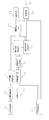
図2は、前記ガス遮断装置2の制御ブロックを示し、9は流速検出手段で、ガス流速を計測する。流速検出手段9としては種々の方式があり、例えば流路内に対向設置された一対の超音波センサからの超音波信号より使用ガス流速を検出するものや、流路内に配置した熱線式センサのインピーダンスより流速を求めるもの、さらには計測膜を用い、同膜の機械的動作を磁石とリードスイッチあるいは磁気抵抗素子等により電気的パルス信号として検出するものがある。
FIG. 2 shows a control block of the gas shut-off
例えば、超音波センサを用いた流速検出手段9の場合、図示していないが超音波を送信または受信する第1送受信器と受信または送信する第2送受信器が流れ方向に対抗して配置され、予め定めた周期毎に上流から下流へ、又下流から上流に向かって超音波信号を送信し、伝搬時間を計測する。 For example, in the case of the flow velocity detection means 9 using an ultrasonic sensor, although not shown, a first transmitter / receiver that transmits or receives ultrasonic waves and a second transmitter / receiver that receives or transmits ultrasonic waves are arranged to oppose the flow direction, An ultrasonic signal is transmitted from the upstream to the downstream and from the downstream to the upstream at predetermined intervals, and the propagation time is measured.
そして、第1送受信器と第2送受信器との超音波の伝搬時間差にもとづき流速を計測して、これに流路の断面積、補正係数などを乗じて流量演算手段10で瞬時流量を演算する。 Then, the flow rate is measured based on the ultrasonic propagation time difference between the first transmitter / receiver and the second transmitter / receiver, and the instantaneous flow rate is calculated by the flow rate calculation means 10 by multiplying this by the cross-sectional area of the flow path, the correction coefficient, etc. .
そして、11は流量記憶手段で、所定流量以上の流量を検出すると機器流量と判定し、その瞬時流量を時系列的に記憶する。 Reference numeral 11 denotes a flow rate storage means. When a flow rate equal to or higher than a predetermined flow rate is detected, the flow rate is determined as a device flow rate, and the instantaneous flow rate is stored in time series.
使用開始以降の流量パターン群として記憶すると共に、大流量域、中流量域、小流量域毎に分類しシリアルの器具番号を付して格納する。 It is stored as a flow rate pattern group after the start of use, and is classified into a large flow rate region, a medium flow rate region, and a small flow rate region, and is stored with serial instrument numbers.
12は平均流量演算手段で、所定周期で求められる瞬時流量を所定個数集合して平均化され平均流量値として算出する。 Reference numeral 12 denotes an average flow rate calculation means, which collects a predetermined number of instantaneous flow rates obtained in a predetermined cycle and averages them to calculate an average flow rate value.
13は器具記憶手段で、各家庭で保有されている器具の流量パターンデータが格納されている。14は距離演算手段で、流量記憶手段11の流量データと器具記憶手段13の流量データとから流量偏差及び標準偏差等の距離値を演算する。
Reference numeral 13 denotes appliance storage means for storing flow rate pattern data of appliances held in each household. A
15は器具識別推定手段で、距離演算手段14の距離データに基づき、現在使用されている器具が何かを推定する。例えば所定流量以上の流量値の変化やピーク流量、ピーク流量以降の流量変化について、流量偏差や標準偏差を求め格納値との距離情報を用いて流量の近い度合いが所定以内かでどの器具かを判定する。
16は器具監視登録手段で、器具識別推定手段15で推定した器具コードを登録するとともに、平均流量演算手段12で求めた平均流量を登録する。求めた平均流量値が所定流量以上の場合器具を表す代表流量として、保安監視対象として登録される。 16 is an appliance monitoring registration means for registering the appliance code estimated by the appliance identification estimating means 15 and for registering the average flow rate obtained by the average flow rate calculating means 12. When the obtained average flow rate value is equal to or higher than the predetermined flow rate, it is registered as a security monitoring target as a representative flow rate representing the appliance.
17は器具監視値設定手段で、器具毎に連続使用制限時間、あるいは使用最大流量の監視判定値などが記憶されている。 17 is an appliance monitoring value setting means for storing the continuous use time limit or the monitoring judgment value of the maximum usage flow rate for each appliance.
18は異常判定手段で、推定した使用器具の監視を行う。例えば器具識別推定手段15でストーブと推定した時、ガスを供給するホースが何らかの原因で外れた時、異常な大流量が発生するが、そのような使用状態を監視するための合計流量遮断値や、ストーブ等の器具の通常使用すると想定した最大使用時間よりはるかに長く使用された場合に対応して使用時間の制限時間を規定した使用時間遮断制限時間を設定されており、この設定値と器具監視登録手段16の登録流量値を異常判定手段18で比較判定することで、登録流量値が使用最大流量値を超えていないか、あるいは器具使用時間が登録流量値に対応した器具連続使用制限時間を超えていないかなど判定する。
この異常判定手段18で異常と判定したとき遮断手段19に遮断信号を送ってガスの供給を停止する。 When the abnormality determination means 18 determines that there is an abnormality, a cutoff signal is sent to the cutoff means 19 to stop the gas supply.
また、遮断状態や遮断内容を液晶表示素子等に表示すると共にガスの安全監視を行っているセンター(図示せず)に通信手段20を通じて通報する。 In addition, the shut-off state and the shut-off content are displayed on the liquid crystal display element and the like, and a center (not shown) that performs gas safety monitoring is notified through the communication means 20.
この時電話回線やインタネット等の伝送媒体21を介して行う。この時属する大流量域、中流量域、小流量域の流量域コードと各々の流量域に属する器具番号を、通信手段20を通じてセンタに通信する。 At this time, it is performed via a transmission medium 21 such as a telephone line or the Internet. The flow rate range codes of the large flow rate range, medium flow rate range, and small flow rate range belonging to this time and the instrument numbers belonging to each flow rate range are communicated to the center through the communication means 20.
通信手段20は、センタ或いは設定器などを介して器具記憶手段13や器具監視値設定手段17に各家庭の保有している器具の流量パターンデータを予め登録することが可能である。 The communication means 20 can register in advance the flow rate pattern data of the appliances owned by each household in the appliance storage means 13 and the appliance monitoring value setting means 17 via a center or a setting device.
次に、本実施の形態におけるガス遮断装置の動作を説明する。 Next, the operation of the gas cutoff device in the present embodiment will be described.
需要家宅で保有しているガス器具、例えばガスファンヒータ8やガス給湯器3などが使用されると、そのときの流速を流速検出手段9で検出し、その流速にもとづき流量演算手段10が流量を演算する。
When a gas appliance held at a customer's house, such as a
例えば、超音波センサを用いた場合は超音波信号の伝搬時間にもとづき流速が検出され、その検出値が流量演算手段10に送られて瞬時流量値として演算され、流量記憶手段11では所定流量以上の流量値を検出すると器具流量と判定し、時系列の流量値が流量パターンとして記憶される。 For example, when an ultrasonic sensor is used, the flow velocity is detected based on the propagation time of the ultrasonic signal, and the detected value is sent to the flow rate calculation means 10 and calculated as an instantaneous flow rate value. When the flow rate value is detected, it is determined that the flow rate is an instrument flow rate, and the time-series flow value is stored as a flow rate pattern.
同時に検出した流量パターンの瞬時流量値より、大流量域、中流量域、小流量域かの流量域コードと流量域毎に分類し器具番号を付して記憶する。 Based on the instantaneous flow rate value of the flow rate pattern detected at the same time, the flow rate code is classified into a large flow rate region, a medium flow rate region, and a small flow rate region and the flow rate region, and an instrument number is assigned and stored.
平均流量演算手段12は所定個数毎の流量より平均流量を演算し、求めた平均流量はN回(n=1〜)前の平均流量と比較し所定流量以上の流量変化があった場合、何らかの器具使用と判定して器具監視登録手段16に使用流量が登録される。 The average flow rate calculating means 12 calculates the average flow rate from the flow rate for each predetermined number, and the obtained average flow rate is compared with the average flow rate N times (n = 1 to) before the flow rate change more than the predetermined flow rate, It is determined that the appliance is used, and the usage flow rate is registered in the appliance monitoring registration means 16.
そして、異常判定手段18は、器具監視登録手段16に登録された使用流量より器具監視値設定手段17に記憶している監視値、すなわち合計流量や増加流量遮断判定を行うとともに、器具識別推定手段15で器具推定された器具コード信号により器具監視値設定手段17の器具毎の使用時間の制限時間値を参照して、使用器具の使用時間を計時し監視する。 Then, the abnormality determination means 18 performs the monitoring value stored in the appliance monitoring value setting means 17 from the use flow rate registered in the appliance monitoring registration means 16, that is, the total flow rate or the increase flow rate cutoff determination, and the appliance identification estimation means. 15, referring to the time limit value of the usage time for each appliance of the appliance monitoring value setting means 17 based on the appliance code signal estimated in 15, the usage time of the appliance used is measured and monitored.
例えば、ガステーブル7やガスファンヒータ8などがリビングや台所で使用され、流量信号を検出し瞬時流量を求めると、距離演算手段14では、まず、流量記憶手段11の記憶している流量パターン群より器具の制御パターン毎、例えば、器具の使用開始時、ピーク流量検出時、安定流量時、制御時等に流量パターンを切り出し分類する。
For example, when the gas table 7 or the
次に、器具記憶手段13の流量データ群、流量パターン群や登録されていた流量とを比較し、各流量制御パターンのブロック毎に比較し距離情報、即ち流量偏差や標準偏差相関関係を求める。 Next, the flow rate data group, the flow rate pattern group, and the registered flow rate in the instrument storage unit 13 are compared, and the distance information, that is, the flow rate deviation and the standard deviation correlation are obtained by comparing each flow rate control pattern block.
器具識別推定手段15では流量の立ち上がり、ピーク流量や安定状態の流量値、流量変化したときの変化流量勾配などより流量偏差などの距離が最も小さい器具を推定する。
The
各制御パターン毎の最も近い、即ち流量偏差、標準偏差が小、相関係数が大の場合、各々の評価点をつけ、もっとも高い器具が使用器具と識別判定し、器具コード信号を出力する。 When each control pattern is the closest, that is, when the flow rate deviation, standard deviation is small, and the correlation coefficient is large, each evaluation point is assigned, the highest instrument is identified and determined as the instrument in use, and an instrument code signal is output.
また、ガステーブル7やガスファンヒータ8などの複数の器具が共に使用中と推定した場合、ガステーブル120分、ガスファンヒータは720分と設定され使用時間監視する。異常判定手段18で異常成立時、即座に遮断信号を遮断手段19に出力する。同時に通信手段20を介してガス事業者のセンタにどのガス器具よる流量異常遮断発生、長時間使用の予告、或いは使用時間遮断の場合は使用時間遮断の発呼通信を行う。
When a plurality of instruments such as the gas table 7 and the
通常の発呼は器具のコード信号、異常内容を示すコード信号と流量区分である。 A normal call is a code signal of an instrument, a code signal indicating an abnormal content, and a flow rate classification.
また、器具監視登録手段16に登録される前に平均流量演算手段12で求めた流量値がホース抜けなどの原因による異常流量を超えていないかも並行して監視する。 In addition, it is also monitored in parallel whether the flow rate value obtained by the average flow rate calculation means 12 before being registered in the appliance monitoring registration means 16 does not exceed the abnormal flow rate due to a cause such as hose disconnection.
なお、本実施の形態に使用した数値限定は一例であり、また、使用形態も本実施の形態に限定されるものではない。 In addition, the numerical limitation used in this embodiment is an example, and the usage pattern is not limited to this embodiment.
以上のように、器具識別推定手段15でどのガス器具を使用しているかを流量偏差や標準偏差等の距離情報を用いて簡単に器具推定することができ、異常判定手段18で使用されているガス器具毎に器具流量の大きさ、および使用時間を並行して監視し、異常な使用のされ方を検出した場合、直ちに遮断することができ、分類し記憶している器具番号を通信手段によりセンタに通報ことにより、ガス事業者にどの器具が異常使用しているかを通知でき、ガス器具需要者の安全を確保し、最悪ガス器具使用によるガス漏れによる一酸化炭素中毒などの生命への危険を防止するとともに、かつガス事業者のセンタに器具番号等情報を通報することにより器具を特定しやすく、早期に安全対策をガス事業者、或いはガス需要家に取らせることができ、極めて安全で、かつ信頼性が高い。
As described above, which gas appliance is used by the appliance identification estimating means 15 can be easily estimated using distance information such as flow rate deviation and standard deviation, and is used by the
以上のように、本発明に係るガス遮断装置は、流量検知するとガス器具を識別特定し、推定した器具毎に最適な遮断判定値を設定し監視することにより器具の保安を適切に確保できるものであり、器具監視装置全般に適用できるものである。 As described above, the gas shutoff device according to the present invention can identify and specify a gas appliance when detecting a flow rate, and can appropriately secure the safety of the appliance by setting and monitoring the optimum cutoff judgment value for each estimated appliance. It can be applied to all instrument monitoring devices.
9 流速検出手段
10 流量演算手段
11 流量記憶手段
12 平均流量演算手段
13 器具記憶手段
14 距離演算手段
15 器具識別推定手段
16 器具監視登録手段
17 器具監視値記憶手段
18 異常判定手段
19 遮断手段
20 通信手段
9 Flow rate detection means 10 Flow rate calculation means 11 Flow rate storage means 12 Average flow rate calculation means 13 Instrument storage means 14 Distance calculation means 15 Instrument identification estimation means 16 Instrument monitoring registration means 17 Instrument monitoring value storage means 18 Abnormality determination means 19 Blocking means 20 Communication means
Claims (1)
Priority Applications (1)
| Application Number | Priority Date | Filing Date | Title |
|---|---|---|---|
| JP2008204087A JP5259297B2 (en) | 2008-08-07 | 2008-08-07 | Gas shut-off device |
Applications Claiming Priority (1)
| Application Number | Priority Date | Filing Date | Title |
|---|---|---|---|
| JP2008204087A JP5259297B2 (en) | 2008-08-07 | 2008-08-07 | Gas shut-off device |
Publications (2)
| Publication Number | Publication Date |
|---|---|
| JP2010038810A true JP2010038810A (en) | 2010-02-18 |
| JP5259297B2 JP5259297B2 (en) | 2013-08-07 |
Family
ID=42011512
Family Applications (1)
| Application Number | Title | Priority Date | Filing Date |
|---|---|---|---|
| JP2008204087A Expired - Fee Related JP5259297B2 (en) | 2008-08-07 | 2008-08-07 | Gas shut-off device |
Country Status (1)
| Country | Link |
|---|---|
| JP (1) | JP5259297B2 (en) |
Cited By (1)
| Publication number | Priority date | Publication date | Assignee | Title |
|---|---|---|---|---|
| WO2010109869A1 (en) | 2009-03-27 | 2010-09-30 | 住友大阪セメント株式会社 | Method for producing positive electrode active material for lithium ion battery, positive electrode active material for lithium ion battery, electrode for lithium ion battery, and lithium ion battery |
Citations (5)
| Publication number | Priority date | Publication date | Assignee | Title |
|---|---|---|---|---|
| JPH07151578A (en) * | 1993-11-29 | 1995-06-16 | Tokyo Gas Co Ltd | Flow rate variation discriminating device |
| JP2005265529A (en) * | 2004-03-17 | 2005-09-29 | Matsushita Electric Ind Co Ltd | Gas shut-off device |
| JP2005291986A (en) * | 2004-04-01 | 2005-10-20 | Matsushita Electric Ind Co Ltd | Gas blocking device |
| JP2006242653A (en) * | 2005-03-01 | 2006-09-14 | Yazaki Corp | Electronic gas meter and safety system using same |
| JP2007024750A (en) * | 2005-07-20 | 2007-02-01 | Matsushita Electric Ind Co Ltd | Flow measuring instrument |
-
2008
- 2008-08-07 JP JP2008204087A patent/JP5259297B2/en not_active Expired - Fee Related
Patent Citations (5)
| Publication number | Priority date | Publication date | Assignee | Title |
|---|---|---|---|---|
| JPH07151578A (en) * | 1993-11-29 | 1995-06-16 | Tokyo Gas Co Ltd | Flow rate variation discriminating device |
| JP2005265529A (en) * | 2004-03-17 | 2005-09-29 | Matsushita Electric Ind Co Ltd | Gas shut-off device |
| JP2005291986A (en) * | 2004-04-01 | 2005-10-20 | Matsushita Electric Ind Co Ltd | Gas blocking device |
| JP2006242653A (en) * | 2005-03-01 | 2006-09-14 | Yazaki Corp | Electronic gas meter and safety system using same |
| JP2007024750A (en) * | 2005-07-20 | 2007-02-01 | Matsushita Electric Ind Co Ltd | Flow measuring instrument |
Cited By (2)
| Publication number | Priority date | Publication date | Assignee | Title |
|---|---|---|---|---|
| WO2010109869A1 (en) | 2009-03-27 | 2010-09-30 | 住友大阪セメント株式会社 | Method for producing positive electrode active material for lithium ion battery, positive electrode active material for lithium ion battery, electrode for lithium ion battery, and lithium ion battery |
| US9216907B2 (en) | 2009-03-27 | 2015-12-22 | Sumitomo Osaka Cement Co., Ltd. | Method of manufacturing positive electrode active material for lithium ion battery, positive electrode active material for lithium ion battery, electrode for lithium ion battery, and lithium ion battery |
Also Published As
| Publication number | Publication date |
|---|---|
| JP5259297B2 (en) | 2013-08-07 |
Similar Documents
| Publication | Publication Date | Title |
|---|---|---|
| WO2009107367A1 (en) | Gas shut-off device and alarm-compatible system meter | |
| JP2006200802A (en) | Gas meter | |
| JP5186760B2 (en) | Gas shut-off device | |
| JP5288600B2 (en) | Gas shut-off device | |
| JP5259297B2 (en) | Gas shut-off device | |
| JP5194684B2 (en) | Flow rate measuring device and gas supply system using this device | |
| JP2008267740A (en) | Gas shut-off device | |
| JP2008134124A (en) | Gas shut-off device | |
| JP5074791B2 (en) | Gas leak detection device | |
| JP5158945B2 (en) | Gas shut-off device | |
| JP4958815B2 (en) | Gas shut-off device | |
| JP5522609B2 (en) | Gas shut-off device | |
| JP5071121B2 (en) | Gas shut-off device | |
| JP4893523B2 (en) | Gas shut-off device and gas supply system | |
| JP5213221B2 (en) | Flow rate measuring device, communication system, flow rate measuring method, flow rate measuring program, and fluid supply system | |
| JP5147111B2 (en) | Gas shut-off device | |
| JP5322260B2 (en) | Gas shut-off device | |
| JP2010038811A (en) | Gas shut-off device | |
| JP5013519B2 (en) | Gas shut-off device and gas supply system | |
| JP5245867B2 (en) | Gas shut-off device | |
| JP5617185B2 (en) | Gas shut-off device | |
| JP2009211465A (en) | Appliance monitoring device | |
| JP2010160089A (en) | Flow measuring device, and determination method of apparatus by flow measuring device | |
| JP5293225B2 (en) | Gas shut-off device | |
| JP5213220B2 (en) | Flow rate measuring device, communication system, flow rate measuring method, flow rate measuring program, and fluid supply system |
Legal Events
| Date | Code | Title | Description |
|---|---|---|---|
| A621 | Written request for application examination |
Free format text: JAPANESE INTERMEDIATE CODE: A621 Effective date: 20110601 |
|
| A131 | Notification of reasons for refusal |
Free format text: JAPANESE INTERMEDIATE CODE: A131 Effective date: 20121002 |
|
| A977 | Report on retrieval |
Free format text: JAPANESE INTERMEDIATE CODE: A971007 Effective date: 20121003 |
|
| A521 | Written amendment |
Free format text: JAPANESE INTERMEDIATE CODE: A523 Effective date: 20121130 |
|
| TRDD | Decision of grant or rejection written | ||
| A01 | Written decision to grant a patent or to grant a registration (utility model) |
Free format text: JAPANESE INTERMEDIATE CODE: A01 Effective date: 20130326 |
|
| A61 | First payment of annual fees (during grant procedure) |
Free format text: JAPANESE INTERMEDIATE CODE: A61 Effective date: 20130424 |
|
| FPAY | Renewal fee payment (event date is renewal date of database) |
Free format text: PAYMENT UNTIL: 20160502 Year of fee payment: 3 |
|
| R150 | Certificate of patent or registration of utility model |
Free format text: JAPANESE INTERMEDIATE CODE: R150 |
|
| LAPS | Cancellation because of no payment of annual fees |