JP2010038534A - Closed type rotary incinerator - Google Patents
Closed type rotary incinerator Download PDFInfo
- Publication number
- JP2010038534A JP2010038534A JP2009111723A JP2009111723A JP2010038534A JP 2010038534 A JP2010038534 A JP 2010038534A JP 2009111723 A JP2009111723 A JP 2009111723A JP 2009111723 A JP2009111723 A JP 2009111723A JP 2010038534 A JP2010038534 A JP 2010038534A
- Authority
- JP
- Japan
- Prior art keywords
- rotating drum
- radioactive waste
- outer shell
- exhaust gas
- gas outlet
- Prior art date
- Legal status (The legal status is an assumption and is not a legal conclusion. Google has not performed a legal analysis and makes no representation as to the accuracy of the status listed.)
- Granted
Links
Images


Abstract
Description
本発明は密閉式回転焼却炉に関するものである。 The present invention relates to a hermetic rotary incinerator.
現在、科学研究の分野において放射性同位元素(以下、RI)を使用することは必須の手段となっている。RIの取り扱いについては「放射性同位元素等による放射性障害の防止に関する法律」が適用される。従って、RI実験に使用した器具等の放射性廃棄物を廃棄する際には、放射線障害の防止のために必要な措置を講じなければならない。 At present, the use of radioisotopes (hereinafter referred to as RI) is an essential means in the field of scientific research. Regarding the handling of RI, the “Act on the Prevention of Radioactive Disorders Caused by Radioisotopes” applies. Therefore, when disposing of radioactive waste such as instruments used in RI experiments, necessary measures must be taken to prevent radiation damage.
従来、RI実験に使用した器具等の放射性廃棄物はそのまま貯蔵されてきたが、貯蔵スペースの観点から、可燃部分を焼却処理する技術への需要があった。放射性廃棄物焼却炉が備えるべき特性としての大前提は、全工程において、炉外に放射性物質の漏洩が生じないことである。 Conventionally, radioactive wastes such as instruments used in RI experiments have been stored as they are, but from the viewpoint of storage space, there has been a demand for technology for incinerating combustible parts. The main premise as a characteristic that the radioactive waste incinerator should have is that no radioactive material leaks outside the furnace in all processes.
また、RI実験に使用した器具には注射針やガラス製容器等も含まれているが、被爆量低減の観点から、これらの金属性廃棄物やガラス製廃棄物を分別せず、そのまま焼却炉に投入できることが好ましい。また、金属性廃棄物やガラス性廃棄物は当該焼却炉内で溶融することなく焼却灰とともに排出されることが好ましく、更に、これらの金属性廃棄物やガラス製廃棄物が混在した焼却灰が容易に排出できることが好ましい。 In addition, although the equipment used for the RI experiment includes a syringe needle and a glass container, from the viewpoint of reducing the amount of exposure, these metal wastes and glass wastes are not separated and are incinerators as they are. It is preferable that it can be introduced into Moreover, it is preferable that the metallic waste and the glassy waste are discharged together with the incineration ash without melting in the incinerator, and further, the incineration ash in which these metallic waste and glass waste are mixed is used. It is preferable that it can be easily discharged.
通常の都市ゴミ等の焼却炉に関して、燃焼効率にすぐれ、かつ、焼却灰が容易に排出できる回転式焼却炉の技術が開示されている(特許文献1)。当該回転式焼却炉は、円錐筒状の炉体の中心線が水平となる状態で回転させつつ、当該炉内の一端に設けた焼却対象物投入口から投入された焼却対象物を加熱乾燥させながら他端に向かって移動させ、乾燥工程を経由しながらバーナーの火元に近づくまでに焼却対象物を充分乾燥させることができるものである。また、当該回転式焼却炉において、焼却対象物投入口の他端開口部は煙道部に回転可能に嵌合されており、該煙道部の底部に灰出し口が設けられた構造を有するため、焼却対象物が燃焼して灰となった灰分を連続的に排出でき、焼却灰の排出性にも優れている。 With respect to ordinary incinerators such as municipal waste, a technology of a rotary incinerator that has excellent combustion efficiency and can easily discharge incineration ash has been disclosed (Patent Document 1). The rotary incinerator heats and drys the incineration object charged from the incineration object input port provided at one end of the furnace while rotating in a state where the center line of the conical cylindrical furnace body is horizontal. The incineration object can be sufficiently dried by moving toward the other end and approaching the fire source of the burner through the drying process. Further, the rotary incinerator has a structure in which the other end opening of the incineration object inlet is rotatably fitted to the flue, and an ash outlet is provided at the bottom of the flue. Therefore, the ash which burned the incineration object and became ash can be discharged continuously, and the discharge property of the incineration ash is excellent.
回転式焼却炉では、円錐筒状の炉体の両端部の開口部から燃焼ガスが漏洩することを防止する手段として、開口部を耐熱性の布シール等で覆い、さらに、運転時には排気ファンにより炉内を負圧に保つ方法が一般的に採用されている。しかし、この方法はシール部の密閉性が完全ではないため、例えば、急激に燃焼するアルコールや油等が多量に混入した場合、炉内の負圧を維持することが困難となる場合がある。このため、前記のように、炉外に放射性物質の漏洩が生じないことが大前提として求められる放射性廃棄物焼却炉として従来の回転式焼却炉を採用することは困難であった。 In a rotary incinerator, as a means to prevent the combustion gas from leaking from the openings at both ends of the conical cylindrical furnace body, the openings are covered with a heat-resistant cloth seal, etc. A method of keeping the inside of the furnace at a negative pressure is generally adopted. However, since this method does not completely seal the sealing portion, for example, when a large amount of alcohol or oil that burns rapidly is mixed, it may be difficult to maintain the negative pressure in the furnace. For this reason, as described above, it has been difficult to adopt a conventional rotary incinerator as a radioactive waste incinerator that is required as a major premise that no leakage of radioactive material occurs outside the furnace.
本発明の目的は炉外に放射性物質の漏洩が生じない密閉式回転焼却炉であって、金属性廃棄物やガラス製廃棄物を分別せず、そのまま焼却炉に投入できることができ、また、これらの金属性廃棄物やガラス製廃棄物が混在した焼却灰の排出性にも優れた密閉式回転焼却炉を提供することである。 An object of the present invention is a sealed rotary incinerator that does not cause leakage of radioactive materials outside the furnace, and can be put into an incinerator as it is without separating metallic waste and glass waste. It is to provide a hermetic rotary incinerator excellent in discharging incineration ash mixed with metallic waste and glass waste.
上記課題を解決するためになされた本発明に係る密閉式回転焼却炉は、中心軸が水平となるように回転可能に支持された回転ドラムと、その外周を覆う密閉構造の外殻と、外殻を貫通して回転ドラムの一端に達する放射性廃棄物投入部と、回転ドラムの他端に接続された排ガス出口部とを備え、これらの放射性廃棄物投入部及び排ガス出口部はそれぞれ外殻に気密にフランジ接続されており、排ガス出口部の下部には回転ドラム内に火炎を吹き込む放射性廃棄物燃焼用バーナーを設け、排ガス出口部の底部には焼却残渣排出口を設けたことを特徴とするものである。 In order to solve the above problems, a sealed rotary incinerator according to the present invention includes a rotary drum that is rotatably supported so that a central axis is horizontal, an outer shell having a sealed structure that covers the outer periphery thereof, and an outer shell. A radioactive waste input part that penetrates the shell and reaches one end of the rotary drum, and an exhaust gas outlet part connected to the other end of the rotary drum, and each of the radioactive waste input part and the exhaust gas outlet part are connected to the outer shell. It is airtightly connected to the flange, and is provided with a radioactive waste combustion burner for blowing a flame into the rotating drum at the lower part of the exhaust gas outlet part, and an incineration residue outlet at the bottom part of the exhaust gas outlet part. Is.
請求項2記載の発明は、請求項1記載の密閉式回転焼却炉において、外殻は燃焼空気導入口を備え、該燃焼空気導入口から外殻内に導入されて、回転ドラム表面からの熱吸収により昇温した空気を、回転ドラム内に導入する燃焼空気流動手段を備えることを特徴とするものである。 According to a second aspect of the present invention, in the sealed rotary incinerator according to the first aspect, the outer shell is provided with a combustion air inlet, and is introduced into the outer shell from the combustion air inlet, so that heat from the surface of the rotary drum can be obtained. Combustion air flow means for introducing air heated by absorption into the rotating drum is provided.
請求項3記載の発明は、請求項1記載の密閉式回転焼却炉において、外殻内圧力検出手段と外殻内圧力調節手段とを備えることを特徴とするものである。 According to a third aspect of the present invention, in the sealed rotary incinerator according to the first aspect of the present invention, the outer shell pressure detecting means and the outer shell pressure adjusting means are provided.
請求項4記載の発明は、請求項1〜3の何れかに記載の密閉式回転焼却炉において、回転ドラム電動駆動手段を外殻外部に備えることを特徴とするものである。 According to a fourth aspect of the present invention, in the sealed rotary incinerator according to any one of the first to third aspects, the rotary drum electric drive means is provided outside the outer shell.
請求項5記載の発明は、請求項1〜4の何れかに記載の密閉式回転焼却炉において、放射性廃棄物投入部が二重ダンパ構造であることを特徴とするものである。
The invention according to
請求項6記載の発明は、請求項5記載の密閉式回転焼却炉において、放射性廃棄物投入部に、更に回転ドラムからの輻射熱を遮熱するための遮熱用ダンパを備えることを特徴とするものである。 A sixth aspect of the present invention is the sealed rotary incinerator according to the fifth aspect, wherein the radioactive waste charging section further includes a heat shield damper for shielding radiant heat from the rotating drum. Is.
請求項7記載の発明は、請求項1〜6の何れかに記載の密閉式回転焼却炉において、放射性廃棄物投入部には、回転ドラム内へ噴霧水を供給するための水噴霧ノズルを備え、排ガス出口部には、温度測定用ノズルと回転ドラム方向に開口した水噴霧ノズルとを備えたことを特徴とするものである。 A seventh aspect of the present invention is the sealed rotary incinerator according to any one of the first to sixth aspects, wherein the radioactive waste charging section is provided with a water spray nozzle for supplying spray water into the rotary drum. The exhaust gas outlet is provided with a temperature measuring nozzle and a water spray nozzle that opens in the direction of the rotating drum.
本発明に係る密閉式回転焼却炉は、回転ドラムを内装する外殻を放射性廃棄物投入部と排ガス出口部とに、各々フランジ接続して外殻内を密閉構造としているため、回転ドラム内に急激に燃焼するアルコールや油等が多量に混入し、回転ドラム内の負圧を維持することが困難となり、回転ドラムの外部に燃焼ガスが漏れた場合であっても、外殻の外部には放射性物質が漏洩する心配はない。 In the sealed rotary incinerator according to the present invention, the outer shell that houses the rotary drum is connected to the radioactive waste input part and the exhaust gas outlet part by flanges, respectively, and the outer shell has a sealed structure. Even if alcohol or oil that burns rapidly is mixed in, it becomes difficult to maintain the negative pressure inside the rotating drum, and even if combustion gas leaks outside the rotating drum, There is no worry about leakage of radioactive material.
また、本発明に係る密閉式回転焼却炉は、放射性廃棄物投入部から投入された放射性廃棄物を、回転ドラム内で回転させつつ、排ガス出口部の下部に設けた放射性廃棄物燃焼用バーナーの火元に近づくまでに充分加熱乾燥させることができるため、外部からの攪拌による粉塵飛散の問題を生じることなく、かつ、燃焼効率よく放射性廃棄物を燃焼させることができる。更に、本発明に係る密閉式回転焼却炉は、排ガス出口部の底部焼却残渣排出口を設けてあり、焼却灰の排出性に優れるため、金属性廃棄物やガラス製廃棄物が混在した焼却灰を容易に排出することができる。したがって、放射性の金属性廃棄物やガラス製廃棄物を分別せず、そのまま焼却炉に投入でき、焼却炉工程における作業者の被爆量低減を図ることができる。 Further, the sealed rotary incinerator according to the present invention is a radioactive waste combustion burner provided at the lower part of the exhaust gas outlet part while rotating the radioactive waste introduced from the radioactive waste input part in the rotary drum. Since it can be sufficiently heated and dried before it approaches the fire source, the radioactive waste can be burned efficiently without causing the problem of dust scattering due to external stirring. Furthermore, the closed rotary incinerator according to the present invention is provided with a bottom incineration residue discharge port at the exhaust gas outlet and is excellent in incineration ash discharge, so that incineration ash mixed with metallic waste and glass waste Can be easily discharged. Therefore, radioactive metallic waste and glass waste can be put into the incinerator without being separated, and the amount of exposure of workers in the incinerator process can be reduced.
請求項2記載の発明によれば、外殻に備えた燃焼空気導入口から外殻内に導入された空気が回転ドラム表面からの熱吸収を行うため、回転ドラムの表面温度上昇抑制を目的として回転ドラム内部にライニングされる耐火材厚を薄肉化することができ、回転ドラムの小型化が可能となる。また、回転ドラム表面からの熱吸収により昇温した空気を、燃焼用空気として回転ドラム内に導入することができるため、熱効率に優れ、二酸化炭素排出量削減に資する。 According to the second aspect of the present invention, the air introduced into the outer shell from the combustion air inlet provided in the outer shell absorbs heat from the surface of the rotating drum. The thickness of the refractory material lined inside the rotating drum can be reduced, and the rotating drum can be downsized. In addition, since air heated by heat absorption from the surface of the rotating drum can be introduced into the rotating drum as combustion air, it has excellent thermal efficiency and contributes to reduction of carbon dioxide emissions.
請求項3記載の発明によれば、外殻内圧力検出手段と外殻内圧力調節手段とにより、密閉式回転焼却炉の負圧管理が可能となり、密閉式回転焼却炉外への放射性物質漏洩をより確実に防止することができる。 According to the third aspect of the invention, the outer shell pressure detecting means and the outer shell pressure adjusting means enable negative pressure management of the sealed rotary incinerator, and leakage of radioactive material to the outside of the sealed rotary incinerator. Can be prevented more reliably.
請求項4記載の発明によれば、回転ドラム電動駆動手段を外殻外部に備えることにより、保守性が向上し、メンテナンス時に作業者の被爆量低減を図ることができる。
According to the invention described in
請求項5記載の発明によれば、放射性廃棄物投入部を二重ダンパ構造とすることにより、廃棄物投入時にも外殻内を負圧に維持することが可能となり、密閉式回転焼却炉外への放射性物質漏洩をより確実に防止することができる。 According to the fifth aspect of the present invention, since the radioactive waste charging section has a double damper structure, it is possible to maintain a negative pressure inside the outer shell even when the waste is charged, and the outside of the rotary rotary incinerator is closed. It is possible to prevent leakage of radioactive material to
請求項6記載の発明によれば、放射性廃棄物投入部の下部先端側に、遮熱用ダンパを設けることにより、回転ドラム内からの輻射熱によって、放射性廃棄物投入部内の温度が上昇し、放射性廃棄物投入部内で、溶剤等の易燃性物質が発火する等の危険を回避することができる。
According to the invention described in
請求項7記載の発明によれば、放射性廃棄物投入部には、回転ドラム内へ噴霧水を供給するための水噴霧ノズルを備え、排ガス出口部には、温度測定用ノズルと回転ドラム方向に開口した水噴霧ノズルとを備えたことにより、回転ドラム内の入口部と出口部とでそれぞれ好ましい温度となるように、温度分布を制御することができる。また、回転ドラム内温度の過熱を防止して、廃棄物に含まれるガラス製廃棄物の溶融を防止し、耐火物の寿命を延ばすことができる。 According to the seventh aspect of the present invention, the radioactive waste input section is provided with a water spray nozzle for supplying spray water into the rotary drum, and the exhaust gas outlet section has a temperature measurement nozzle and a rotary drum direction. By providing the opened water spray nozzle, the temperature distribution can be controlled so that the inlet portion and the outlet portion in the rotating drum have preferable temperatures. In addition, it is possible to prevent overheating of the temperature inside the rotating drum, prevent melting of glass waste contained in the waste, and extend the life of the refractory.
図1は本発明に係る密閉式回転焼却炉の一実施形態における側面断面図を表わし、図2は図1におけるA−A断面図を表わしている。図3は他の実施形態における密閉式回転焼却炉の側面断面図を表わしている。 FIG. 1 shows a side cross-sectional view of an embodiment of a sealed rotary incinerator according to the present invention, and FIG. 2 shows a cross-sectional view taken along line AA in FIG. FIG. 3 shows a side sectional view of a closed rotary incinerator in another embodiment.
以下、図面に基づいて本発明の構成を説明する。
本発明の密閉式回転焼却炉は、図1に示すように、放射性廃棄物投入部1と排ガス出口部2と回転ドラム3と外殻4から構成されている。
The configuration of the present invention will be described below with reference to the drawings.
As shown in FIG. 1, the sealed rotary incinerator of the present invention includes a radioactive
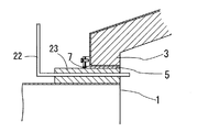
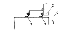
回転ドラム3は、SUSまたは炭素鋼の内面に耐火材をライニングした構造を有し、放射性廃棄物投入部1と排ガス出口部2との間で、中心線が水平となるように回転可能に支持されている。回転ドラム3と放射性廃棄物投入部1との間隙5は、図4に示すようにシール部材7で覆われ、回転ドラム3と排ガス出口部2との間隙6は、図5に示すようにシール部材7覆われている。
The rotating
該シール部材7は、耐熱性の布シール等であって、回転ドラム3が摺動可能に接している。なお、電動駆動手段14は保守性の観点から、外殻4の外部に設けられ、回転ドラム電動駆動手段14が外殻4を貫通する部分はオイルシールにより、外殻4の密閉性を確保している。
The
外殻4は、炭素鋼からなり、図2に示すように、回転ドラム3を回転式支持手段20により回転可能に内装する構造を有する。外殻4両端に設けられた開口部8のうち、一端には放射性廃棄物投入部1がフランジ接続され、他端には排ガス出口部2がフランジ接続され、外殻4内を密閉構造としている。外殻4は燃焼空気導入口12と燃焼空気流動手段13とを備え、更に、外殻内圧力検出手段15と外殻内圧力調節手段と、逃し弁取付ノズル16を備えている。
The
放射性廃棄物投入部1は、投入口に放射性廃棄物投入用ダンパ9a、9bを二重に重ねて備え、下部にはプッシャー10を備えている。
The radioactive
放射性廃棄物投入部1は、更に、下部先端側に、回転ドラム3内からの輻射熱を遮熱するための遮熱用ダンパ21を備えている。該遮熱用ダンパ21は、放射性廃棄物投入部1内で可能な限り回転ドラム3側に設け、放射性廃棄物投入部1内の温度上昇を阻止することが好ましい。また、該遮熱用ダンパ21には、開閉機構を備え、通常は閉状態として放射性廃棄物を回転ドラム3に投入する際にのみ開状態として、放射性廃棄物投入部1内の温度上昇を阻止している。
The radioactive
また、放射性廃棄物投入部1の下部先端の外周には、回転ドラム3内へ噴霧水を供給するための水噴霧ノズル22を備えている。該水噴霧ノズル22は、放射性廃棄物投入部1の下部先端の外周側に固定形成された水噴霧ノズル収納用ボックス部23に収納されている。
Further, a
排ガス出口部2の下部には回転ドラム3方向に開口したノズルを備えた放射性廃棄物燃焼用バーナー11、底部には焼却残渣排出口17が設けられている。更に、排ガス出口部は温度測定用ノズル18と回転ドラム方向に開口した水噴霧ノズル19とを備えるものである。
At the lower part of the
以下、上記構成における作用を説明する。 Hereinafter, the operation of the above configuration will be described.
本発明に係る密閉式回転焼却炉は、RI実験に使用した器具等の放射性廃棄物を焼却処理するための焼却炉である。RI実験に使用した器具には注射針やガラス製容器等も含まれるが、被爆量低減の観点から、これらの金属性廃棄物やガラス製廃棄物を分別せず、そのまま焼却炉に投入することが好ましい。一般に放射性廃棄物はRI施設等で袋詰めや容器詰めされて保管されており、本発明に係る密閉式回転焼却炉は、これらをそのまま(分別せず袋や容器ごと)放射性廃棄物投入部1に投入可能としたものである。 The sealed rotary incinerator according to the present invention is an incinerator for incineration of radioactive waste such as instruments used in RI experiments. Instruments used for RI experiments include injection needles and glass containers, but from the viewpoint of reducing the amount of exposure, do not separate these metal wastes and glass wastes and put them directly into the incinerator. Is preferred. In general, radioactive wastes are stored in bags or containers in RI facilities and the like, and the sealed rotary incinerator according to the present invention directly stores them (without sorting and in bags and containers). Can be introduced into
放射性廃棄物投入部1の投入口には放射性廃棄物投入用ダンパ9a、9bが2段に設けられているため、廃棄物投入時には、まず放射性廃棄物投入用ダンパ9aを開き、放射性廃棄物投入用ダンパ9bは閉じて放射性廃棄物を投入し、次に放射性廃棄物投入用ダンパ9aを閉じた後、放射性廃棄物投入用ダンパ9bを開いて放射性廃棄物を放射性廃棄物投入部1の下部に投入する。
Since the radioactive
放射性廃棄物投入用ダンパ9bを開いて放射性廃棄物投入部1の下部に投入された放射性廃棄物が所定量となった段階で、遮熱用ダンパ21を開き、プッシャー10により回転ドラム3内に押し出し投入する。
When the radioactive
このように、放射性廃棄物投入部1に放射性廃棄物投入用ダンパ9a、9bを2段に設けることにより、放射性廃棄物投入時にも外殻4及び回転ドラム3内部を負圧に保つことが可能となり、放射性物質の漏洩が有効に防止でき、作業者の被爆量低減が図られる。
Thus, by providing the radioactive
また、更に、放射性廃棄物投入部1の下部先端側に、遮熱用ダンパ21を設けることにより、回転ドラム3内からの輻射熱によって、放射性廃棄物投入部1内の温度が上昇し、放射性廃棄物投入部1内で、溶剤等の易燃性物質が発火する等の危険を回避することができる。
Furthermore, by providing a heat-shielding
回転ドラム3は放射性廃棄物投入部1と排ガス出口部2との間で、中心線が水平となるように回転可能に支持されており、間隙5、6はシール部材7覆われているが、シール部材7は、耐熱性の布シール等であって、回転ドラム3が摺動可能に接する構造を有する。当該部分のシール性は完全ではないが、通常運転時には、排ガス出口部2に繋がる排ガスファンにより、回転ドラム3内の空気は負圧に保たれており、当該シール部材7の隙間から放射性物質の漏洩が生じることはない。しかし、例えば、回転ドラム3内にアルコールや油等の揮発性成分が多量に混入し燃焼条件変動に伴う暴走が生じた場合には、回転ドラム3内の空気を負圧に保つことが困難となり、当該シール部材7の隙間から放射性物質の漏洩が生じる可能性がある。そこで、本発明では、回転ドラム3全体を覆うように外殻4を設け、外殻4内を密閉構造とすることにより、前記のような燃焼条件変動にも対応可能な構造としている。
The
回転ドラム3内に導入された放射性廃棄物は、回転ドラム3の回転に伴って、回転ドラム3の他端に向かって移動しながら加熱乾燥され、排ガス出口部2の下部に設けられた放射性廃棄物燃焼用バーナー11の火元付近で燃焼する。
The radioactive waste introduced into the
燃焼用空気は主にバーナー11の下端から供給される。また、その他に、外殻4に設けた燃焼空気導入口12から導入した燃焼用空気が、放射性廃棄物投入部1に接続した配管13aを通じて回転ドラム3内に供給される。なお、放射性廃棄物投入部1の下部先端側には、遮熱用ダンパ21を設けているが、該遮熱用ダンパ21は、仕切り空間の密閉性確保を目的とするものではなく、遮熱効果を奏するものであれば良く、該配管13aから回転ドラム3内への燃焼空気の流動を確保するための隙間を有している。
Combustion air is mainly supplied from the lower end of the
更に、図3に示すように、外殻4に設けた燃焼空気導入口12から導入した燃焼用空気を、バーナー11の火元付近から回転ドラム3内に挿入された、噴出ノズル付配管13bを通じて回転ドラム3内に送り込む方法を採用することもできる。
Further, as shown in FIG. 3, the combustion air introduced from the combustion
該外殻4に設けた燃焼空気導入口12から導入した燃焼用空気は、回転ドラム3表面及び外殻4表面からの熱吸収を行う作用も有する。回転ドラム3表面温度は、許容応力の観点から350〜400℃以下とし、外殻4表面温度は、外傷防止の観点から、80℃以下とすることが望ましい。このような表面温度とする手段として、外殻4内面に保温材を施工したり、回転ドラム3の内面にライニングする耐火材を厚くしたり、断熱性にすぐれた素材を用いる方法もあるが、いずれも、焼却炉の大型化や、高コスト化に繋がり望ましくない。この点、本発明のように、燃焼空気を利用した熱交換方法によれば、前記デメリットを回避して、焼却炉の小型化や、低コスト化が可能となる。なお、熱吸収後の燃焼用空気の一部はシール部材7の隙間から回転ドラム3内に入り、残りは、前記配管13a、13bを通じて回転ドラム3内に供給される。
The combustion air introduced from the
本発明に係る密閉式回転焼却炉は、RI実験に使用した器具等の放射性廃棄物を焼却処理するための焼却炉であり、廃棄物に溶剤等の易燃性物質が多く含まれることもある。このような場合、回転ドラム3の入口側3aを300〜400℃、出口側3bを700〜800℃の温度分布となるように制御して、易燃性物質の急激な燃焼を防止することが好ましい。本発明では、当該温度分布を実現する手段として、放射性廃棄物投入部1の下部先端の外周には、回転ドラム3内へ噴霧水を供給するための水噴霧ノズル22を備えている。該水噴霧ノズル22から噴霧する液体によって、回転ドラム3の入口側3aの耐火物温度を低下させることができる。なお、該水噴霧ノズル22から噴霧する液体として、RI実験に使用した廃水の希釈液を用いることにより、RI実験廃液の処理も同時に行うこともできる。但し、該温度分布を得る手段は、水噴霧に限定されるものではなく、圧縮空気の供給等の手段を採用することも可能である。
The closed rotary incinerator according to the present invention is an incinerator for incineration of radioactive waste such as instruments used in RI experiments, and the waste may contain a lot of flammable substances such as solvents. . In such a case, it is possible to control the
回転ドラム3の出口側3bは、排ガス出口部2の下部に設けられた放射性廃棄物燃焼用バーナー11の熱源からのエネルギーと、放射性廃棄物の燃焼エネルギーとで回転ドラム3内温度は800℃程度に維持されている。回転ドラム3内温度が約900℃を超えると放射性廃棄物に混入しているガラスの粘性が増してくるが、耐火物寿命の観点から、当該ガラス溶融は防止することが好ましい。当該ガラス溶融防止手段として、排ガス出口部2に温度測定用ノズル18と水噴霧ノズル19とを備え、回転ドラム3内温度がバーナ11を停止しても約900℃を超える過熱状態となった場合、回転ドラム3の出口側3b温度が800℃程度となるように水を噴霧できるようにしている。
The
回転ドラム3内での廃棄物焼却後に残った焼却残渣は排ガス出口部2の底部に設けられた焼却残渣排出口17から排出される。当該焼却残渣排出口17には密閉構造の振動コンベアー又はスクリュードライバーコンベア−が接続され、密閉状態を保ったまま次工程に送られるため、本発明の焼却残渣排出工程においても放射性物質が外部に漏洩することなく、安全に処理可能な構造となっている。
The incineration residue remaining after the waste incineration in the
外殻4に備えられた外殻内圧力検出手段15では、外殻4内の圧力を検出し、外殻4内の圧力が−0.5〜−5kPa、望ましくは−1〜−2kPaとなるように外郭内圧力調節手段で調節している。外殻内圧力調節手段としては、例えば、排ガスブロワ及び圧力調整弁を採用することができる。なお、外殻4には、逃し弁取付ノズル15を設け、逃し弁、HFPAフィルタに接続することにより、廃棄物中に多量の揮発性物質が混入して急激に燃焼し、回転ドラム3内及び外殻4内の圧力が正圧となった場合でも、放射性物質が外殻4外に漏洩することなく、安全に処理することができる。
The outer shell pressure detection means 15 provided in the
外殻4には燃焼空気導入口12を備え、燃焼用空気の一部を当該燃焼空気導入口12から外殻4内に導入して、回転ドラム3表面及び外殻4表面から熱吸収を行わせている。これにより、回転ドラム3表面及び外殻4表面を冷却することができる。回転ドラム3表面温度は、許容応力の観点から350〜400℃以下とし、外殻4表面温度は、外傷防止の観点から、80℃以下とすることが望ましい。このような表面温度とする手段として、外殻4内面に保温材を施工したり、回転ドラム3の内面にライニングする耐火材を厚くしたり、断熱性にすぐれた素材を用いる方法もあるが、いずれも、焼却炉の大型化や、高コスト化に繋がり望ましくない。この点、本発明のように、燃焼空気を利用した熱交換方法によれば、前記デメリットを回避して、焼却炉の小型化や、低コスト化が可能となる。なお、熱吸収後の燃焼用空気の一部はシール部材7の隙間から回転ドラム3内に入り、残りは、燃焼空気流動手段により回転ドラム3内に送り込まれる。
The
1 放射性廃棄物投入部
2 排ガス出口部
3 回転ドラム
3a 入口側
3b 出口側
4 外殻
5 回転ドラムと放射性廃棄物投入部との間隙
6 回転ドラムと排ガス出口部との間隙
7 シール部材
8 開口部
9a、9b 放射性廃棄物投入用ダンパ
10 プッシャー
11 放射性廃棄物燃焼用バーナー
12 燃焼空気導入口
13 燃焼空気流動手段
13a、13b 配管
14 回転ドラム電動駆動手段
15 外殻内圧力検出手段
16 逃し弁取付ノズル
17 焼却残渣排出口
18 温度測定用ノズル
19 水噴霧ノズル
20 回転式支持手段
21 遮熱用ダンパ
22 水噴霧ノズル
23 水噴霧ノズル収納用ボックス部
DESCRIPTION OF
7
Claims (7)
これらの放射性廃棄物投入部及び排ガス出口部はそれぞれ外殻に気密にフランジ接続されており、
排ガス出口部の下部には回転ドラム内に火炎を吹き込む放射性廃棄物燃焼用バーナーを設け、
排ガス出口部の底部には焼却残渣排出口を設けたことを特徴とする密閉式回転焼却炉。 A rotating drum that is rotatably supported so that its central axis is horizontal, a sealed outer shell that covers the outer periphery of the rotating drum, a radioactive waste input unit that passes through the outer shell and reaches one end of the rotating drum, and a rotating drum An exhaust gas outlet connected to the other end of the
These radioactive waste input part and exhaust gas outlet part are airtightly flange-connected to the outer shell,
At the lower part of the exhaust gas outlet part, a burner for radioactive waste combustion that blows flame into the rotating drum is installed,
A closed rotary incinerator characterized in that an incineration residue discharge port is provided at the bottom of the exhaust gas outlet.
該燃焼空気導入口から外殻内に導入されて、回転ドラム表面からの熱吸収により昇温した空気を、回転ドラム内に導入する燃焼空気流動手段を備えることを特徴とする請求項1記載の密閉式回転焼却炉。 The outer shell has a combustion air inlet,
2. The combustion air flow means for introducing the air introduced into the outer shell from the combustion air inlet and heated up by heat absorption from the surface of the rotating drum into the rotating drum. Closed rotary incinerator.
Priority Applications (1)
| Application Number | Priority Date | Filing Date | Title |
|---|---|---|---|
| JP2009111723A JP5498052B2 (en) | 2008-07-08 | 2009-05-01 | Closed rotary incinerator |
Applications Claiming Priority (3)
| Application Number | Priority Date | Filing Date | Title |
|---|---|---|---|
| JP2008177491 | 2008-07-08 | ||
| JP2008177491 | 2008-07-08 | ||
| JP2009111723A JP5498052B2 (en) | 2008-07-08 | 2009-05-01 | Closed rotary incinerator |
Publications (2)
| Publication Number | Publication Date |
|---|---|
| JP2010038534A true JP2010038534A (en) | 2010-02-18 |
| JP5498052B2 JP5498052B2 (en) | 2014-05-21 |
Family
ID=42011271
Family Applications (1)
| Application Number | Title | Priority Date | Filing Date |
|---|---|---|---|
| JP2009111723A Active JP5498052B2 (en) | 2008-07-08 | 2009-05-01 | Closed rotary incinerator |
Country Status (1)
| Country | Link |
|---|---|
| JP (1) | JP5498052B2 (en) |
Cited By (5)
| Publication number | Priority date | Publication date | Assignee | Title |
|---|---|---|---|---|
| CN102141250A (en) * | 2011-04-14 | 2011-08-03 | 任荣 | Incinerator for incinerating wastes by using pulverized coal burner |
| JP2011174776A (en) * | 2010-02-24 | 2011-09-08 | Ngk Insulators Ltd | Incineration method for granular radioactive waste and incineration apparatus therefor |
| JP2011174628A (en) * | 2010-02-23 | 2011-09-08 | Ngk Insulators Ltd | Incineration method of waste ion exchange resin |
| JP2013101088A (en) * | 2011-11-10 | 2013-05-23 | Ngk Insulators Ltd | Radioactive waste incinerator and radioactive waste incineration processing method |
| JP2015224807A (en) * | 2014-05-26 | 2015-12-14 | オオノ開發株式会社 | Pcb waste batch incineration system |
Citations (7)
| Publication number | Priority date | Publication date | Assignee | Title |
|---|---|---|---|---|
| JPH05223227A (en) * | 1992-02-13 | 1993-08-31 | Masanori Nakayama | Waste fuel incinerator |
| JPH05322147A (en) * | 1992-05-21 | 1993-12-07 | Hitachi Zosen Corp | Rotary furnace |
| JPH08128611A (en) * | 1994-10-31 | 1996-05-21 | Hosobuchii Eng:Kk | Incinerator |
| JPH09310830A (en) * | 1996-05-22 | 1997-12-02 | Komahide:Kk | Rotary kiln type drying combustion apparatus |
| JPH102535A (en) * | 1996-06-13 | 1998-01-06 | Kuchiku Kogyo Kk | Incinerating device and method of water-containing fluid substance |
| JP2002060754A (en) * | 2000-08-11 | 2002-02-26 | Shin Caterpillar Mitsubishi Ltd | Continuous carbonizing apparatus and continuous carbonizing method |
| JP2003320359A (en) * | 2002-04-30 | 2003-11-11 | Advanced:Kk | Method and apparatus for pyrolyzing organic waste |
-
2009
- 2009-05-01 JP JP2009111723A patent/JP5498052B2/en active Active
Patent Citations (7)
| Publication number | Priority date | Publication date | Assignee | Title |
|---|---|---|---|---|
| JPH05223227A (en) * | 1992-02-13 | 1993-08-31 | Masanori Nakayama | Waste fuel incinerator |
| JPH05322147A (en) * | 1992-05-21 | 1993-12-07 | Hitachi Zosen Corp | Rotary furnace |
| JPH08128611A (en) * | 1994-10-31 | 1996-05-21 | Hosobuchii Eng:Kk | Incinerator |
| JPH09310830A (en) * | 1996-05-22 | 1997-12-02 | Komahide:Kk | Rotary kiln type drying combustion apparatus |
| JPH102535A (en) * | 1996-06-13 | 1998-01-06 | Kuchiku Kogyo Kk | Incinerating device and method of water-containing fluid substance |
| JP2002060754A (en) * | 2000-08-11 | 2002-02-26 | Shin Caterpillar Mitsubishi Ltd | Continuous carbonizing apparatus and continuous carbonizing method |
| JP2003320359A (en) * | 2002-04-30 | 2003-11-11 | Advanced:Kk | Method and apparatus for pyrolyzing organic waste |
Cited By (5)
| Publication number | Priority date | Publication date | Assignee | Title |
|---|---|---|---|---|
| JP2011174628A (en) * | 2010-02-23 | 2011-09-08 | Ngk Insulators Ltd | Incineration method of waste ion exchange resin |
| JP2011174776A (en) * | 2010-02-24 | 2011-09-08 | Ngk Insulators Ltd | Incineration method for granular radioactive waste and incineration apparatus therefor |
| CN102141250A (en) * | 2011-04-14 | 2011-08-03 | 任荣 | Incinerator for incinerating wastes by using pulverized coal burner |
| JP2013101088A (en) * | 2011-11-10 | 2013-05-23 | Ngk Insulators Ltd | Radioactive waste incinerator and radioactive waste incineration processing method |
| JP2015224807A (en) * | 2014-05-26 | 2015-12-14 | オオノ開發株式会社 | Pcb waste batch incineration system |
Also Published As
| Publication number | Publication date |
|---|---|
| JP5498052B2 (en) | 2014-05-21 |
Similar Documents
| Publication | Publication Date | Title |
|---|---|---|
| JP2013101088A (en) | Radioactive waste incinerator and radioactive waste incineration processing method | |
| JP5498052B2 (en) | Closed rotary incinerator | |
| CN110139920A (en) | Thermal decomposition gasification furnace including automatic grey processor | |
| CA2891630C (en) | Device for centrifugal combustion by area using flow of combustion air | |
| KR20040086074A (en) | A vertical incinerator for buring refuses and its controlling method | |
| JP3426562B2 (en) | Vertical waste incinerator for incineration of industrial waste | |
| KR101073661B1 (en) | Apparatus for incinerating radioactive waste matter | |
| CN106989399A (en) | Incinerator | |
| CN106989401A (en) | Incinerator apptss | |
| JP2001090922A (en) | Rotary kiln | |
| CN103939916A (en) | Garbage incinerator feeding device having water-cooling and fire-fighting functions | |
| CN108758639B (en) | Garbage pyrolysis gasification and secondary combustion chamber integrated device | |
| JPH1019220A (en) | Rotary kiln | |
| EA014625B1 (en) | Neutralizer of combustible solid domestic wastes | |
| KR102046329B1 (en) | Incineration apparatus for hot water/wind | |
| RU2507448C1 (en) | Neutraliser of biowaste | |
| RU2791278C1 (en) | Furnace for radioactive waste burning | |
| JP2016121252A (en) | Carbonization furnace, aqueous gas generation system, and control method of carbonization furnace | |
| CN215001608U (en) | Fire grate device for radioactive waste pyrolyzing furnace | |
| JP6326212B2 (en) | Radioactive waste incinerator | |
| JP7245144B2 (en) | Stoker type incinerator | |
| JP5385819B2 (en) | Incineration of waste ion exchange resin | |
| JP6276956B2 (en) | Radioactive waste incinerator | |
| JP5517672B2 (en) | Incineration processing method and apparatus for incineration of granular radioactive waste | |
| KR100500338B1 (en) | Waste incineration apparatus and waste incineration method |
Legal Events
| Date | Code | Title | Description |
|---|---|---|---|
| A621 | Written request for application examination |
Free format text: JAPANESE INTERMEDIATE CODE: A621 Effective date: 20120215 |
|
| A977 | Report on retrieval |
Free format text: JAPANESE INTERMEDIATE CODE: A971007 Effective date: 20130712 |
|
| A131 | Notification of reasons for refusal |
Free format text: JAPANESE INTERMEDIATE CODE: A131 Effective date: 20130726 |
|
| A521 | Written amendment |
Free format text: JAPANESE INTERMEDIATE CODE: A523 Effective date: 20130911 |
|
| A131 | Notification of reasons for refusal |
Free format text: JAPANESE INTERMEDIATE CODE: A131 Effective date: 20131203 |
|
| A521 | Written amendment |
Free format text: JAPANESE INTERMEDIATE CODE: A523 Effective date: 20131225 |
|
| TRDD | Decision of grant or rejection written | ||
| A01 | Written decision to grant a patent or to grant a registration (utility model) |
Free format text: JAPANESE INTERMEDIATE CODE: A01 Effective date: 20140304 |
|
| A61 | First payment of annual fees (during grant procedure) |
Free format text: JAPANESE INTERMEDIATE CODE: A61 Effective date: 20140307 |
|
| R150 | Certificate of patent or registration of utility model |
Ref document number: 5498052 Country of ref document: JP Free format text: JAPANESE INTERMEDIATE CODE: R150 |