JP2010038458A - Steam quality monitoring apparatus - Google Patents
Steam quality monitoring apparatus Download PDFInfo
- Publication number
- JP2010038458A JP2010038458A JP2008202346A JP2008202346A JP2010038458A JP 2010038458 A JP2010038458 A JP 2010038458A JP 2008202346 A JP2008202346 A JP 2008202346A JP 2008202346 A JP2008202346 A JP 2008202346A JP 2010038458 A JP2010038458 A JP 2010038458A
- Authority
- JP
- Japan
- Prior art keywords
- steam
- heat exchanger
- flow rate
- valve
- boiler
- Prior art date
- Legal status (The legal status is an assumption and is not a legal conclusion. Google has not performed a legal analysis and makes no representation as to the accuracy of the status listed.)
- Granted
Links
Images

Abstract
Description
本発明は、ボイラからの蒸気を冷媒を用いて凝縮水にする熱交換器と、この熱交換器からの凝縮水の水質を計測する計測手段とを用いて、ボイラで発生される蒸気中の不純物量を連続的にモニタリングする蒸気質のモニタリング装置に関するものである。 The present invention uses a heat exchanger that converts steam from a boiler into condensed water using a refrigerant, and a measuring means that measures the quality of condensed water from the heat exchanger, The present invention relates to a vapor quality monitoring device that continuously monitors the amount of impurities.
蒸気の製品への直接吹き込みによる製品の加熱や殺菌作業の一般化と、小型貫流ボイラの普及に伴って、蒸気中の不純物量、すなわち、蒸気の質(品質)が問題となる。小型貫流ボイラ(JIS B8223では特殊循環ボイラと定義されている)は、比較的安価で使い勝手はよいが、気水分離器の能力が低く、発生した蒸気中に不純物を含み易い傾向に有るからである。このため、このような場合に、蒸気を連続的にサンプリングして、蒸気中の不純物量を常時監視し、蒸気の質が悪化した場合には、蒸気を使用しないようにする蒸気質モニタリング装置(特許文献1)が提案されている。 With the generalization of product heating and sterilization operations by direct blowing of steam into products and the spread of small once-through boilers, the amount of impurities in steam, that is, the quality (quality) of steam, becomes a problem. Small once-through boilers (defined as special circulation boilers in JIS B8223) are relatively inexpensive and easy to use, but the capability of the steam separator is low and the generated steam tends to contain impurities. is there. For this reason, in such a case, a vapor quality monitoring device that continuously samples the vapor and constantly monitors the amount of impurities in the vapor and prevents the vapor from being used when the vapor quality deteriorates ( Patent Document 1) has been proposed.
この蒸気質モニタリング装置100は、図2で示されるように、冷却水Cを用いて蒸気Sを冷却して、これを凝縮水Gにする熱交換器101と、熱交換器101から出た凝縮水G中の不純物量を計測する計測装置102とを有している。この蒸気質モニタリング装置100では、蒸気Sの質を精度良く計測するために、計測装置102に供給される凝縮水Gの流量を一定にする必要があるとともに、この凝縮水Gの温度を上限値以下の一定値にする必要がある。
As shown in FIG. 2, the steam
このため、この蒸気質モニタリング装置100では、熱交換器101出口の凝縮水ラインに、流量計103と流量調整弁104とを設け、凝縮水Gの流量が一定になるように、制御部110を介して、流量調節弁104の開度を自動的にコントロールしている。また、この蒸気質モニタリング装置100では、熱交換器100に対する冷却水Cの供給ラインに温度調整弁105を設けるとともに、熱交換器101出口の凝縮水ラインに温度計106を設け、熱交換器101出口の凝縮水Gの温度が一定になるように、制御部110を介して、温度調整弁105の開度を自動的にコントロールしている。
For this reason, in this vapor
一方、この蒸気質モニタリング装置100では、ボイラの運転が停止して、熱交換器101に蒸気を供給する蒸気配管107内の蒸気圧が低下すると、電磁弁108が閉じられて蒸気配管107が遮断されるとともに、ボイラが運転を再開し、蒸気配管107内の蒸気圧が上昇すると、電磁弁108が開けられて、この蒸気配管107からボイラ側の蒸気Sが取り込まれるようになっている。
On the other hand, in the steam
ところで、上記蒸気質モニタリング装置100では、ボイラの運転が停止して電磁弁108が閉じられると、電磁弁108上流側の蒸気配管107内に、蒸気が冷やされて凝縮した凝縮排水が溜められるが、この凝縮排水が、ボイラの運転再開によって電磁弁108が開けられると、熱交換器101側に一気に流れ込んでしまう。このことにより、蒸気配管107内で生じていた腐食生成物等のスラッジも、凝縮排水とともに熱交換器101側に移動してしまい、これが、電磁弁108直前の蒸気配管107に設けられた蒸気フィルター(不図示)を閉塞させてしまうという問題があった。
By the way, in the steam
このため、上記従来の蒸気質モニタリング装置100では、蒸気フィルターの清掃又は取り替え回数が増えるとともに、蒸気配管107のフラッシング回数が増えて、蒸気質のモニタリング作業に支障をきたすという問題があった。
For this reason, the conventional steam
また、小型貫流ボイラで発生される蒸気の圧力は、例えば、0.6〜0.8MPaのように、一般的に約0.2MPaの幅で大きく振れ、この蒸気圧の変動に伴って、上記蒸気質モニタリング装置100に供給される蒸気の流量は変動する。ところが、上記蒸気質モニタリング装置100では、この蒸気の流量の変動を、凝縮水G側の流量調整弁104が充分にコントロールできない場合もあり、結果として、計測器102側に流れる凝縮水Gの流量が不安定になって、一定のなりにくいという問題があった。
In addition, the pressure of the steam generated in the small once-through boiler, for example, oscillates greatly in a width of about 0.2 MPa, such as 0.6 to 0.8 MPa, and the fluctuation of the steam pressure causes the above The flow rate of the steam supplied to the steam
さらに、上記蒸気質モニタリング装置100では、凝縮水Gの流量コントロールに、自動的に制御される高価な流量調整弁104や制御部110を使用しているので、装置がコスト高になってしまうという問題があるとともに、流量調整弁104の作動トラブルも少なくないという問題があった。このことは、凝縮水Gの温度を自動的にコントロールをする温度調整弁105に関しても同様のことがいえる。
Furthermore, in the said vapor
この発明は、以上の点に鑑み、ボイラの運転開始時に、蒸気配管内の凝縮排水とともに持ち込まれるスラッジに起因して、蒸気質のモニタリング作業に支障を来すことのない蒸気質のモニタリング装置を提供することを第1の目的とする。 In view of the above, the present invention provides a steam quality monitoring device that does not hinder the steam quality monitoring work due to sludge brought in along with the condensed drainage in the steam pipe at the start of boiler operation. The first purpose is to provide it.
また、この発明は、上記第1の目的に加えて、蒸気質のモニタリングに当たり、ボイラ側で蒸気圧力の変動が生じても、熱交換器出口の凝縮水の流量を、コストをかけずに、かつ、作動トラブルも少ない状態で、確実に一定に保つことができる蒸気質のモニタリング装置を提供することを第2の目的とする。 Further, in addition to the first object, the present invention, in addition to the monitoring of the steam quality, even if the steam pressure fluctuates on the boiler side, the flow rate of the condensed water at the outlet of the heat exchanger can be reduced without cost. A second object of the present invention is to provide a vapor quality monitoring device that can be reliably kept constant with few operation troubles.
さらに、この発明は、上記第2の目的に加え、熱交換器出口の凝縮水の温度を、コストをかけずに、かつ、作動トラブルも生じさせることなく、上限値より小さい一定値に保つことができる蒸気質のモニタリング装置を提供することを第3の目的とする。 Furthermore, in addition to the second object, the present invention keeps the temperature of the condensed water at the outlet of the heat exchanger at a constant value smaller than the upper limit value without incurring costs and causing operational troubles. It is a third object to provide a vapor quality monitoring device capable of performing the above.
この発明の請求項1記載の発明は、ボイラからの蒸気を冷媒を用いて凝縮水にする熱交換器と、この熱交換器からの前記凝縮水の水質を計測する計測手段とを用いて、前記ボイラで発生される蒸気中の不純物量を連続的にモニタリングする蒸気質のモニタリング装置において、前記熱交換器に前記蒸気を供給する前記ボイラからの蒸気配管端部に、この蒸気配管内の蒸気の凝縮によって生じた凝縮排水を排出するスチームトラップを設け、かつ、前記蒸気配管と前記熱交換器とを、この蒸気配管内の前記凝縮排水が流れ込まないようにした、この蒸気配管からの分岐配管により接続したことを特徴とする。 Invention of Claim 1 of this invention uses the heat exchanger which makes the vapor | steam from a boiler into condensed water using a refrigerant | coolant, and the measurement means which measures the water quality of the said condensed water from this heat exchanger, In the steam quality monitoring device for continuously monitoring the amount of impurities in the steam generated in the boiler, the steam in the steam pipe is connected to the end of the steam pipe from the boiler that supplies the steam to the heat exchanger. A branch pipe from the steam pipe is provided with a steam trap that discharges the condensed waste water generated by the condensation of the steam pipe, and the steam pipe and the heat exchanger are prevented from flowing in the condensed waste water in the steam pipe. It is characterized by having connected by.
この発明では、ボイラの運転が開始され、このボイラからの蒸気配管内に溜められていた凝縮排水が蒸気に押されて熱交換器側に向かっても、この凝縮排水は、熱交換器側には移動せず、蒸気配管端部のスチームトラップから外部に排出される。したがって、蒸気配管内の腐食生成物等からなるスラッジも、凝縮排水とともにスチームトラップ側へ移動し、このスチームトラップを介して外部に排出される。なお、蒸気配管内のボイラからの蒸気は、分岐配管を通って、熱交換器側に送られる。 In this invention, the operation of the boiler is started, and even if the condensed waste water stored in the steam pipe from this boiler is pushed by the steam toward the heat exchanger side, this condensed waste water is not supplied to the heat exchanger side. Does not move and is discharged to the outside from the steam trap at the end of the steam pipe. Therefore, the sludge consisting of corrosion products in the steam pipe also moves to the steam trap side together with the condensed waste water, and is discharged to the outside through this steam trap. Note that steam from the boiler in the steam pipe passes through the branch pipe and is sent to the heat exchanger side.
この発明の請求項2記載の発明は、請求項1記載の発明の場合において、前記ボイラからの前記蒸気配管又は前記分岐配管に、前記熱交換器入口の前記蒸気の圧力を、前記ボイラによる圧力変動の影響を受けない一定圧に減圧する減圧弁を設け、かつ、前記熱交換器と前記計測手段間の前記凝縮水ラインに、前記凝縮水の流量計測手段と、手動により弁開度の設定と固定とがなされる手動式の流量調整弁とを設けたことを特徴とする。 According to a second aspect of the present invention, in the case of the first aspect of the present invention, the steam pressure at the inlet of the heat exchanger is applied to the steam pipe or the branch pipe from the boiler. A pressure reducing valve for reducing the pressure to a constant pressure not affected by fluctuations is provided, and the condensate flow rate measuring means is manually set in the condensed water line between the heat exchanger and the measuring means, and the valve opening is manually set. And a manual flow rate adjusting valve that is fixed.
この発明では、熱交換器入口の蒸気圧力は、減圧弁により、ボイラによる圧力変動の影響を受けない一定圧まで減圧される。このため、熱交換器出口の凝縮水の圧力は一定となり、熱交換器出口の凝縮水の流量は、この凝縮水ラインに設けられた流量調整弁の開度によって定まることとなる。したがって、この凝縮水ラインに設けられた流量計測手段の値を見つつ、これが所定値になるように、流量調整弁の開度を手動により設定した後、例えば、流量調整弁の開閉ハンドルを取り外して、この流量調整弁の開度を固定することにより、熱交換器出口の凝縮水の流量を所定の一定値に定めることができる。 In this invention, the steam pressure at the inlet of the heat exchanger is reduced to a constant pressure that is not affected by pressure fluctuations caused by the boiler by the pressure reducing valve. For this reason, the pressure of the condensed water at the outlet of the heat exchanger becomes constant, and the flow rate of the condensed water at the outlet of the heat exchanger is determined by the opening degree of the flow rate adjusting valve provided in the condensed water line. Therefore, while looking at the value of the flow rate measuring means provided in this condensate line and manually setting the opening of the flow rate adjustment valve so that it becomes a predetermined value, for example, remove the opening / closing handle of the flow rate adjustment valve Thus, by fixing the opening of the flow rate adjusting valve, the flow rate of the condensed water at the outlet of the heat exchanger can be set to a predetermined constant value.
この発明の請求項3記載の発明は、請求項2記載の発明の場合において、前記熱交換器に対する前記冷媒の排出ラインに、この冷媒の温度計測手段を設けるとともに、前記熱交換器に対する前記冷媒の供給ライン又は前記排出ラインに、この冷媒の流量計測手段を設け、かつ、前記冷媒の供給ラインに、前記熱交換器出口の冷媒温度が所定の設定値より小さくなるような量だけ、この熱交換器に前記冷媒を流すように、手動により弁開度の設定と固定とがなされる手動式の流量調整弁と、前記ボイラの運転開始とともに開かれる電磁弁とを直列に配置した第1の流量調整ユニットを設け、さらに、前記冷媒の供給ラインに前記第1の流量調整ユニットとは並列に、前記熱交換器出口の冷媒温度が前記設定値に達して、前記凝縮水の温度が上限値に近づく異常時に、前記第1の流量調整ユニットに追加して、所定量だけ前記熱交換器に前記冷媒を流すように、手動により弁開度の設定と固定とがなされる手動式の流量調整弁と、前記異常時に開かれる電磁弁とを直列に配置した第2の流量調整ユニットを設けたことを特徴とする。 According to a third aspect of the present invention, in the case of the second aspect, the refrigerant temperature measuring means is provided in the refrigerant discharge line for the heat exchanger, and the refrigerant for the heat exchanger is provided. The refrigerant flow rate measuring means is provided in the supply line or the discharge line, and the heat is supplied to the refrigerant supply line by an amount such that the refrigerant temperature at the outlet of the heat exchanger is smaller than a predetermined set value. A first manual flow rate adjusting valve, in which the valve opening is manually set and fixed, and an electromagnetic valve that is opened when the boiler is started are arranged in series so that the refrigerant flows through the exchanger. A flow rate adjustment unit is provided, and the refrigerant supply line is parallel to the first flow rate adjustment unit, the refrigerant temperature at the outlet of the heat exchanger reaches the set value, and the temperature of the condensed water is the upper limit. In the event of an abnormality approaching, the valve opening is manually set and fixed so that the refrigerant flows through the heat exchanger by a predetermined amount in addition to the first flow rate adjustment unit. A second flow rate adjustment unit is provided in which a valve and an electromagnetic valve opened in the event of an abnormality are arranged in series.
この発明では、熱交換器出口の冷媒の温度が所定の設定値を超えると、熱交換器出口の凝縮水の温度が上限値に近づき好ましくないので、通常のモニタリング時には、第1の流量調整ユニットの電磁弁を開き、第1の流量調整ユニットの流量調節弁を用いて、熱交換器出口の冷媒の温度が所定の設定値より小さくなるような一定の流量だけ、熱交換器に冷媒を流す。この場合、熱交換器出口の凝縮水の流量は一定であるので、蒸気が熱交換器に持ち込む熱量は、ボイラ側の蒸気圧の変動により僅かに変動するが、ほぼ一定と考えられる。このため、この発明では、第1の流量調整ユニットを使用することにより、凝縮水の温度を一定に定めることができる。 In the present invention, when the temperature of the refrigerant at the outlet of the heat exchanger exceeds a predetermined set value, the temperature of the condensed water at the outlet of the heat exchanger approaches the upper limit value. And the refrigerant is allowed to flow through the heat exchanger at a constant flow rate such that the temperature of the refrigerant at the outlet of the heat exchanger becomes smaller than a predetermined set value by using the flow rate regulating valve of the first flow rate regulating unit. . In this case, since the flow rate of the condensed water at the outlet of the heat exchanger is constant, the amount of heat that the steam brings into the heat exchanger varies slightly due to fluctuations in the steam pressure on the boiler side, but is considered to be substantially constant. For this reason, in this invention, the temperature of condensed water can be fixed by using a 1st flow volume adjustment unit.
また、この発明では、熱交換器出口の冷媒温度が何らかの原因によって設定値を超え、熱交換器出口の凝縮水の温度が上限値に近づく異常時には、第1の流量調整ユニットに追加して、第2の流量調整ユニットの電磁弁も開き、第1の流量調整ユニットの流量調節弁をも用いて、熱交換器に十分な量の冷媒を供給し、熱交換器出口の凝縮水の温度が上限値を超えないようにする。 Further, in the present invention, when the refrigerant temperature at the heat exchanger outlet exceeds the set value for some reason and the temperature of the condensed water at the outlet of the heat exchanger approaches the upper limit value, it is added to the first flow rate adjustment unit, The electromagnetic valve of the second flow rate adjustment unit is also opened, and a sufficient amount of refrigerant is supplied to the heat exchanger using the flow rate adjustment valve of the first flow rate adjustment unit. Do not exceed the upper limit.
この発明の請求項1記載の発明によれば、ボイラからの蒸気配管内で発生した腐食生成物等からなるスラッジを、凝縮排水とともに、スチームトラップを介して外部に排出できるので、スラッジに起因して蒸気質のモニタリング作業に支障を来すことはなく、連続的で安定した蒸気質のモニタリングができるようになる。 According to the invention described in claim 1 of the present invention, sludge composed of corrosion products generated in the steam pipe from the boiler can be discharged to the outside through the steam trap together with the condensed waste water. Therefore, it is possible to monitor the vapor quality continuously and stably without hindering the vapor quality monitoring work.
この発明の請求項2記載の発明によれば、安価な減圧弁と安価な手動式の流量調整弁を設けることにより、熱交換器出口の凝縮水の流量を一定にすることができる。このため、この発明によれば、自動的に凝縮水の流量を一定にする高価な流量調整弁を設ける必要がなく、設備のコストを下げることができるとともに、設備の作動トラブルも減少させることができる。また、これらの発明では、熱交換器入口の蒸気圧力を一定にしているので、熱交換器に供給される蒸気の流量がボイラの影響を受けず、凝縮水の流量も確実に一定にすることができる。 According to the second aspect of the present invention, the flow rate of the condensed water at the outlet of the heat exchanger can be made constant by providing an inexpensive pressure reducing valve and an inexpensive manual flow rate adjusting valve. For this reason, according to the present invention, it is not necessary to provide an expensive flow rate adjustment valve that automatically keeps the flow rate of the condensed water constant, the cost of the equipment can be reduced, and the trouble of the equipment can be reduced. it can. In these inventions, since the steam pressure at the heat exchanger inlet is constant, the flow rate of the steam supplied to the heat exchanger is not affected by the boiler, and the flow rate of the condensed water is also ensured to be constant. Can do.
この発明の請求項3記載の発明によれば、安価な手動式の流量調整弁と安価な電磁弁からなる流量調整ユニットを複数組み設けることにより、熱交換器出口の凝縮水温度を、異常時においても上限値を超えさせることなく、一定にすることができる。このため、この発明によれば、自動的に凝縮水の温度を一定にする高価な流量調整弁を設ける必要がなく、設備のコストを下げることができるとともに、設備の作動トラブルも減少させることができる。 According to the invention described in claim 3 of the present invention, by providing a plurality of sets of flow rate adjusting units each including an inexpensive manual flow rate adjusting valve and an inexpensive electromagnetic valve, the condensate temperature at the outlet of the heat exchanger can be set at an abnormal time. In the case of, it is possible to make it constant without exceeding the upper limit value. For this reason, according to the present invention, it is not necessary to provide an expensive flow rate adjusting valve that automatically keeps the temperature of the condensed water constant, the cost of the equipment can be reduced, and the operation trouble of the equipment can be reduced. it can.
以下、この発明の実施の形態を図面を参照しつつ説明する。
図1はこの発明の一実施の形態に係る蒸気質モニタリング装置を示している。
Embodiments of the present invention will be described below with reference to the drawings.
FIG. 1 shows a vapor quality monitoring apparatus according to an embodiment of the present invention.
蒸気質モニタリング装置1は、小型貫流ボイラ(以下ボイラという)からの蒸気を冷却して凝縮水にした後、この凝縮水の水質を連続的に計測し、この凝縮水の水質から、ボイラで発生される蒸気の品質を連続的に調べよう(監視しよう)とするものである。 The steam quality monitoring device 1 cools the steam from a small once-through boiler (hereinafter referred to as a boiler) to condensate, then continuously measures the quality of the condensate, and is generated in the boiler from the quality of the condensate. It is intended to continuously check (monitor) the quality of the generated steam.
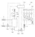
この蒸気質モニタリング装置1は、図1で示されるように、熱交換器2と、計測装置3と、蒸気供給ライン4と、凝縮水ライン5と、冷却水供給ライン6と、冷却水排出ライン7と、制御部8と、運転状態表示部9とから構成されている。 As shown in FIG. 1, the steam quality monitoring device 1 includes a heat exchanger 2, a measuring device 3, a steam supply line 4, a condensed water line 5, a cooling water supply line 6, and a cooling water discharge line. 7, a control unit 8, and an operation state display unit 9.
熱交換器2は、蒸気供給ライン4を介して供給された蒸気Sを、冷媒である冷却水Cによって冷却し、この蒸気Sを、所定温度で所定流量の凝縮水Gにするためのものである。この熱交換器2では、例えば、蒸気Sが上部から下部に向かって、冷却水Cが下部から上部に向かって、それぞれ対向するように流される。 The heat exchanger 2 is for cooling the steam S supplied via the steam supply line 4 with cooling water C as a refrigerant, and converting the steam S into condensed water G having a predetermined flow rate at a predetermined temperature. is there. In the heat exchanger 2, for example, the steam S flows from the upper part to the lower part, and the cooling water C flows from the lower part to the upper part so as to face each other.
計測装置3は、凝縮水G中の不純物量を計測する計測手段であり、溶存酸素計30と、電気伝導度計31と、pH計32と、これらの計器30,31,32で計測された計測値を表示・記録するための表示記録部33と、計測後の凝縮水Gを排出する排出部34とを有している。溶存酸素濃度計30は、凝縮水G中の溶存酸素濃度を計測するものであり、これによって、蒸気S中に含まれる酸素量の多少が判断される。電気伝導度計31は、凝縮水Gの電気伝導度を計測するものであり、これによって、蒸気S中の無機性の不純物量の多少が判断される。pH計は、凝縮水GのpH値を計測するものであり、これによって、蒸気S中のpH影響成分の多少が判断される。計測が終了した凝縮水Gは、排出部34から外部に排出される。計測された、溶存酸素濃度値、電気伝導度値、pH値は、表示記録部33に表示されるとともに、記録される。
The measuring device 3 is a measuring means for measuring the amount of impurities in the condensed water G, and was measured by a dissolved oxygen meter 30, an electric conductivity meter 31, a
ここで、計測装置3に供給される凝縮水Gの流量や温度が、計測中に変動する場合には、計測装置3による計測結果と、蒸気S中の不純物量との関係が、一定とならず、計測結果の再現性が良好でなくなる。また、計測装置3に供給される凝縮水Gの温度には、計測装置3を保護する観点から、上限値(例えば40℃)が設けられている。 Here, when the flow rate and temperature of the condensed water G supplied to the measuring device 3 fluctuate during the measurement, the relationship between the measurement result by the measuring device 3 and the amount of impurities in the steam S is constant. Therefore, the reproducibility of the measurement result is not good. In addition, the temperature of the condensed water G supplied to the measuring device 3 is provided with an upper limit value (for example, 40 ° C.) from the viewpoint of protecting the measuring device 3.
蒸気供給ライン4は、熱交換器2にボイラからの蒸気Sを供給するためのものである。この蒸気供給ライン4は、ボイラ側配管と接続される蒸気配管としての蒸気サンプリング配管40と、この蒸気サンプリング配管40からから分岐し、蒸気サンプリング配管40内の蒸気Sを熱交換器2に供給する分岐配管41と、蒸気サンプリング配管40端部の下向き配管部40a下端に設けられたスチームトラップ42と、スチームトラップ42に接続されるドレン配管43とを有している。また、この蒸気供給ライン4は、分岐配管41中に、蒸気フィルター44と、減圧弁45と、電磁弁46とを有している。
The steam supply line 4 is for supplying steam S from the boiler to the heat exchanger 2. The steam supply line 4 branches from the
分岐配管41は、蒸気サンプリング配管40内の蒸気Sが凝縮して生じる凝縮排水を熱交換器2側に持ち込まないように、蒸気サンプリング配管40端部の下向き配管部40から水平に分岐されている。なお、分岐配管41は、図1中2点斜線で示されるように、蒸気サンプリング配管40との接合部が上向きに立ち上がり、蒸気サンプリング配管40内の凝縮排水が熱交換器2側に流れ込まないようにしたものであってもよい。減圧弁45は、上流側の一次側蒸気圧力を下流側の二次側蒸気圧力まで減圧して、この二次側蒸気圧力を一定に保つものである。
The
凝縮水ライン5は、熱交換器2で作られた凝縮水Gを計測装置3に供給するためのものである。この凝縮水ライン5は、熱交換器2から計測装置3までの凝縮水配管50と、この凝縮水配管50中に設けられた、流量調整弁51、凝縮水流量計52,及び凝縮水温度計53とを有すとともに、凝縮水流量計52と凝縮水温度計53の間に分岐ライン54を有している。流量調整弁51は、手動で弁開度が調整できるとともに、例えば、開閉ハンドルを動かないようにロックするか又は取り外すことにより、手動で弁開度が固定できる手動式の流量調整可能な弁、例えばニードル弁である。
The condensed water line 5 is for supplying the measuring device 3 with the condensed water G produced by the heat exchanger 2. The condensed water line 5 includes a condensed water pipe 50 from the heat exchanger 2 to the measuring device 3, and a flow
冷却水供給ライン6は、熱交換器2に冷却水Cを供給するためのものである。この冷却水供給ライン6は、熱交換器2と冷却水源とを連結する冷却水入口配管60と、この冷却水入口配管60中に設けられた冷却水流量計61と、冷却水流量計61より下流側の冷却水入口配管60中に互いに並列に設けられる、第1及び第2流量調整ユニット62,63とを有している。
The cooling water supply line 6 is for supplying the cooling water C to the heat exchanger 2. The cooling water supply line 6 includes a cooling
第1流量調整ユニット62は、通常のモニタリング時に、冷却水出口ライン7の冷却水Cの温度が所定の設定値(例えば、70℃)より低くなるような流量だけ、熱交換器2に冷却水Cを供給し、熱交換器2出口の凝縮水Gの温度を所定の一定値に保つ機能を有するものである。この第1流量調整ユニット62は、電磁弁62aと、この電磁弁62aより下流側に配置される流量調整弁62bと、これらを繋ぐ配管62cとから構成されている。流量調整弁61cは、流量調整弁51と同様な弁であり、手動で弁開度が調整できるとともに、手動で弁開度が固定できる手動式の流量調整可能な弁、例えばニードル弁である。
The first flow
第2流量調整ユニット63は、冷却水出口ライン7の冷却水温度が設定値(70℃)に達して、凝縮水Gの温度が上限値(40℃)に近づく異常時に、第1流量調整ユニット62に追加して、所定量だけ熱交換器2に冷却水Cを供給し、冷却水出口ライン7の冷却水温度を設定値(70℃)より下げて、熱交換器2出口の凝縮水Gの温度を下げる働きを有するものである。この第2流量調整ユニット63は、電磁弁63aと、この電磁弁63aより下流側に配置される流量調整弁63bと、これらを繋ぐ配管63cとから構成されている。流量調整弁63cも、流量調整弁62cと同様に、手動で弁開度が調整できるとともに、手動で弁開度が固定できる手動式の流量調整可能な弁、例えばニードル弁である。
The second flow
冷却水排出ライン7は、熱交換器2で温められた冷却水Cを排出するためのものである。この冷却水排出ライン7は、熱交換器2に連結される冷却水出口配管70と、この冷却水出口配管70中に設けられた冷却水温度計71とを有している。
The cooling water discharge line 7 is for discharging the cooling water C warmed by the heat exchanger 2. The cooling water discharge line 7 includes a cooling
制御部8は、電磁弁46,62a,63aを所定のタイミングで開閉させるものである。電磁弁46は、ボイラが作動して、減圧弁45の下流側蒸気圧力が所定値になると、自動的に開けられ、ボイラが停止して、減圧弁45の下流側蒸気圧力が所定値より小さくなると自動的に閉じられる。電磁弁62aは、電磁弁46が開く前に自動的に開き、電磁弁46が閉まった後に自動的に閉まる。電磁弁63aは、冷却水排出ライン7の冷却水Cの温度が設定値(70℃)に達した場合の異常時に、自動的に開けられる。なお、これらの電磁弁46,62a,63aは、制御部8からのマニュアル信号によっても、開閉できるようになっている。
The control unit 8 opens and closes the
運転状態表示部9は、凝縮水流量計52及び凝縮水温度計53からの出力(凝縮水流量と凝縮水温度)を表示するとともに、冷却水流量計61及び冷却水温度計71からの出力(冷却水流量と、熱交換器2出口の冷却水温度)を表示する。
The operation state display unit 9 displays outputs from the
つぎに、この蒸気質モニタリング装置1の使用前の設定作業について、具体例をあげて説明する。なお、この場合、ボイラからの蒸気Sには、設定蒸気圧が例えば0.7MPaの飽和蒸気が用いられるものとし、冷却水Cには、入口温度が20℃の水道水が用いられるものとする。 Next, setting work before use of the vapor quality monitoring apparatus 1 will be described with a specific example. In this case, saturated steam having a set steam pressure of 0.7 MPa, for example, is used for the steam S from the boiler, and tap water having an inlet temperature of 20 ° C. is used for the cooling water C. .
まず、冷却水供給ライン6から、例えば1.5L/分の冷却水Cが熱交換器2に供給されるようにする。この作業は、第1流量調整ユニット62の電磁弁62aを開けた状態で、冷却水流量計61の指示値を見つつ、第1流量調整ユニット62の流量調整弁62bの開度を手動で調整することにより行う。冷却水流量計61の指示値が1.5L/分となった状態で、流量調整弁62bの開閉ハンドルを動かないようにロックして、その弁開度を固定する。
First, for example, 1.5 L / min of cooling water C is supplied from the cooling water supply line 6 to the heat exchanger 2. This operation is performed by manually adjusting the opening degree of the flow
つづいて、凝縮水Gの流量が一定値、例えば100mL/分になるように設定する。
ボイラの設定蒸気圧が0.7MPaの場合、このボイラの蒸気圧は、一般に、0.6〜0.8MPaの範囲で変動する。そこで、まず、蒸気供給ライン4の減圧弁45の二次側圧力を、ボイラの蒸気圧の影響を受けない圧力、例えば、0.4MPaに設定する。つづいて、蒸気供給ライン4の電磁弁46を開けて、蒸気Sを熱交換器2に通した状態で、凝縮水流量計52の指示値を見つつ、縮水ライン5における流量調整弁51を手動で開けていく。そして、凝縮水流量計52の指示値が100mL/分となった状態で、流量調整弁51の開閉ハンドルを動かないようにロックして、その弁開度を固定する。この場合、凝縮水温度計53の指示値が凝縮水Gの上限値(40℃)より小さいことを確認しておく。
Subsequently, the flow rate of the condensed water G is set to a constant value, for example, 100 mL / min.
When the set steam pressure of the boiler is 0.7 MPa, the steam pressure of the boiler generally varies in the range of 0.6 to 0.8 MPa. Therefore, first, the secondary pressure of the
上記の状態で、ボイラの蒸気圧が0.6〜0.8MPaの範囲で変動しても、減圧弁45により熱交換器2の入口側で蒸気圧を固定し、かつ、熱交換器2の出口側で流量調整弁51により凝縮水Gの流量を固定している。したがって、流量調整弁51を通過する凝縮水Gの流量は、ボイラの蒸気圧力が変動しても、当初の設定通り、100mL/分で一定となる。
In the above state, even if the steam pressure of the boiler fluctuates in the range of 0.6 to 0.8 MPa, the steam pressure is fixed on the inlet side of the heat exchanger 2 by the
一方、凝縮水Gの温度は、蒸気Sが熱交換器2に持ち込んだ総熱量(凝縮水Gの流量に蒸気Sのエンタルピーを掛けた値)から、熱交換器2の吸熱量を引いた値によって定まる。この場合、蒸気Sのエンタルピは、ボイラの蒸気圧が変動すると変動するが、変動幅はは小さく、ほぼ一定と考えられる。また、熱交換器2の吸熱量も、冷却水Cの入口温度と流量が一定であれば、一定と考えられる。したがって、凝縮水Gの温度は、凝縮水Gの流量が一定になったことにより、一定になると考えられる。なお、凝縮水Gの温度を変更するには、第1流量調整ユニット62の流量調整弁62bの開度を変更し、熱交換器2に流れ込む冷却水Cの流量を変えてやればよい。
On the other hand, the temperature of the condensed water G is a value obtained by subtracting the amount of heat absorbed by the heat exchanger 2 from the total amount of heat (the value obtained by multiplying the flow rate of the condensed water G by the enthalpy of the steam S) brought into the heat exchanger 2. It depends on. In this case, the enthalpy of the steam S changes when the steam pressure of the boiler changes, but the fluctuation range is small and is considered to be almost constant. Further, the heat absorption amount of the heat exchanger 2 is also considered to be constant if the inlet temperature and flow rate of the cooling water C are constant. Therefore, it is considered that the temperature of the condensed water G becomes constant as the flow rate of the condensed water G becomes constant. In order to change the temperature of the condensed water G, the flow rate of the cooling water C flowing into the heat exchanger 2 may be changed by changing the opening degree of the flow
つづいて、何らかの原因(例えば、冷却水Cの入口温度の急激な上昇や、凝縮水G流量の急激な上昇)によって、凝縮水Gの温度が上昇しても、この凝縮水Gが上限値(40℃)を超えないようにする設定について説明する。 Subsequently, even if the temperature of the condensed water G increases due to some cause (for example, a rapid increase in the inlet temperature of the cooling water C or a rapid increase in the flow rate of the condensed water G), the condensed water G remains at the upper limit value ( (40 ° C.) will be described below.
例えば、蒸気Sの圧力が0.7MPa、凝縮水Gの流量が100mL/分、凝縮水Gの温度が25℃、冷却水Cの流量が1.5L/分、冷却水Cの入口温度が20℃の場合、冷却水Cの出口温度は約62℃となる。一方、上記状態で、冷却水Cの入口温度の上昇により、凝縮水Gの温度が上限値(40℃)になった場合、熱交換器2の冷却水Cの出口温度は80℃近くまで上昇する。また、上記状態で、凝縮水Gの流量の増加により、凝縮水Gの温度が上限値(40℃)になった場合においても、熱交換器2の冷却水Cの出口温度は80℃近くまで上昇する。したがって、冷却水Cの出口温度が、例えば70℃の設定温度になった異常時には、その後、凝縮水Gの温度が上限値を超えないようにするための対策が必要となる。 For example, the pressure of the steam S is 0.7 MPa, the flow rate of the condensed water G is 100 mL / min, the temperature of the condensed water G is 25 ° C., the flow rate of the cooling water C is 1.5 L / min, and the inlet temperature of the cooling water C is 20 In the case of ° C, the outlet temperature of the cooling water C is about 62 ° C. On the other hand, when the temperature of the condensed water G reaches the upper limit (40 ° C.) due to the rise in the inlet temperature of the cooling water C in the above state, the outlet temperature of the cooling water C of the heat exchanger 2 rises to nearly 80 ° C. To do. Moreover, even when the temperature of the condensed water G reaches the upper limit (40 ° C.) due to the increase in the flow rate of the condensed water G in the above state, the outlet temperature of the cooling water C of the heat exchanger 2 is close to 80 ° C. To rise. Therefore, when the outlet temperature of the cooling water C becomes abnormal, for example, at a set temperature of 70 ° C., a countermeasure is required to prevent the temperature of the condensed water G from exceeding the upper limit value thereafter.
そこで、このような異常時には、冷却水Cの流量を、例えば、2.5L/分とする。この場合、例えば、冷却水Cの入口温度が15℃上昇して35℃になると、凝縮水Gの出口温度も15℃上昇して40℃になるが、冷却水Cの出口温度がほぼ60℃に抑えられ、かつ、冷却水Cの流量増加に伴い、熱交換器2の熱伝達係数も増加するので、凝縮水Gの温度が上限温度(40℃)を超えるのが防止される。また、この場合、例えば、凝縮水Gの流量が150mL/分に上昇した場合でも、凝縮水Gの温度が上限温度(40℃)を超えるのが防止される。 Therefore, at the time of such an abnormality, the flow rate of the cooling water C is set to, for example, 2.5 L / min. In this case, for example, when the inlet temperature of the cooling water C is increased by 15 ° C. to 35 ° C., the outlet temperature of the condensed water G is also increased by 15 ° C. to 40 ° C., but the outlet temperature of the cooling water C is approximately 60 ° C. And the heat transfer coefficient of the heat exchanger 2 increases as the flow rate of the cooling water C increases, so that the temperature of the condensed water G is prevented from exceeding the upper limit temperature (40 ° C.). In this case, for example, even when the flow rate of the condensed water G is increased to 150 mL / min, the temperature of the condensed water G is prevented from exceeding the upper limit temperature (40 ° C.).
熱交換器2への冷却水Cの流量を2.5L/分にするには、冷却水供給ライン6において、第1流量調整ユニット62とともに、第2流量調整ユニット63を使用すればよい。すなわち、流量調整弁62bの開度設定が終了している第1流量調整ユニット62の電磁弁62aとともに、第2流量調整ユニット63の電磁弁63aを開けた状態で、冷却水流量計61の指示値を見つつ、第2流量調整ユニット63の流量調整弁63bを手動で開けていく。そして、冷却水流量計61の指示値が2.5L/分になった時点で、流量調整弁63bの開度を固定すればよい。
In order to set the flow rate of the cooling water C to the heat exchanger 2 to 2.5 L / min, the second flow
つぎに、この蒸気質モニタリング装置1の作用効果について説明する。
ボイラが作動して、蒸気供給ライン4の減圧弁45下流側の蒸気圧が、例えば、0.4MPa近くに達すると、まず、冷却水供給ライン6において第1流量調整ユニット62の電磁弁62aが開いて、熱交換器2内に冷却水Cが供給される。その後一定時間を経て、蒸気供給ライン4の電磁弁46が開いて、熱交換器2内に蒸気Sが供給される。このことにより、熱交換器2には所定流量(1.5L/分)の冷却水Cが供給されるとともに、熱交換器2に供給された蒸気Sは、上記冷却水Cによって、所定流量(100mL/分)で所定温度の凝縮水Gになるまで冷却される。熱交換器2を出た凝縮水Gは、凝縮水ライン5を通って計測装置3に供給され、この計測装置3によって、溶存酸素濃度と、電気伝導率と、pHとが計測され、これらの値が、表示記録部33に記録されるとともに表示される。そして、計測が終了した凝縮水Gは、排出部34から外部に排出される。
Next, operational effects of the vapor quality monitoring apparatus 1 will be described.
When the boiler operates and the steam pressure on the downstream side of the
上記状態において、ボイラからの蒸気Sの圧力が変動しても、この蒸気Sは、減圧弁45により、ボイラの蒸気圧の影響を受けない圧力まで減圧されて、熱交換器2に供給されるので、凝縮水ライン5中の流量調整弁51は蒸気Sの圧力変動の影響を受けない。したがって、流量調整弁51を通った凝縮水Gは、常に一定の流量で計測装置3に供給される。また、熱交換器2への冷却水Cの供給温度と供給流量とが一定であり、かつ、凝縮水Gの流量が一定であるため、凝縮水Gの温度も一定となり、この凝縮水Gは、常に一定の温度で計測装置3に供給される。したがって、計測装置3によって長時間に亘って計測された、凝縮水Gの水質値(溶存酸素濃度値、電気伝導率値、pH値)に基づいて、この間の蒸気S中の不純物量の多少を、精度良く判断することができる。
In the above state, even if the pressure of the steam S from the boiler fluctuates, the steam S is decompressed by the
つづいて、ボイラの運転が停止され、減圧弁45出口の二次側の蒸気圧が0.3MPaを下まわると、蒸気供給ライン4の電磁弁46が閉じられ、その後一定時間を経て、冷却水供給ライン6において、第1流量調整ユニット62の電磁弁62aが閉じられる。
Subsequently, when the operation of the boiler is stopped and the steam pressure on the secondary side of the outlet of the
一方、ボイラの運転中に何らかの原因により、冷却水排出ライン7の冷却水Cの温度が70℃に達すると、凝縮水Gの温度が上限値に近づいてくるので、第2流量調整ユニット63の電磁弁63aが開けられ、熱交換器2には、第1流量調整ユニット62からだけでなく、第2流量調整ユニット63からも冷却水Cが供給される。このため、熱交換器2には、合計2.5L/分の冷却水Cが供給され、冷却水排出ライン7の冷却水Cの温度が下げられるとともに、凝縮水Gの温度も下げられ、この温度が上限値に達するのが防止される。この場合、警報を発するようにして、作業者がその後の措置をとれるようにしてもよい。
On the other hand, when the temperature of the cooling water C in the cooling water discharge line 7
また、ボイラが停止している間は、ボイラから続く蒸気供給ライン4内の蒸気Sは冷却され、凝縮排水となって蒸気供給ライン4内に溜められる。このため、ボイラの運転が再開され、蒸気供給ライン4の電磁弁4が開けられて、熱交換器2に蒸気Sが供給されると、蒸気供給ライン4内の凝縮排水が、この蒸気供給ライン4内で発生していた腐食生成物等のスラッジとともに、熱交換器2側に移動し、蒸気フィルター44を閉塞させようとする。ところが、この蒸気供給ライン4の主要部となる蒸気サンプリング配管40内の凝縮排水は、蒸気サンプリング配管40から分岐した、熱交換器2側への分岐配管41に流れ込むことはなく、蒸気サンプリング配管40端部の下向き配管部40a側に流れ、スチームトラップ42を通って、ドレン配管42により外部に排出される。
Further, while the boiler is stopped, the steam S in the steam supply line 4 continuing from the boiler is cooled and condensed in the steam supply line 4 as condensed drainage. For this reason, when the operation of the boiler is resumed, the solenoid valve 4 of the steam supply line 4 is opened, and the steam S is supplied to the heat exchanger 2, the condensed waste water in the steam supply line 4 becomes the steam supply line. 4 moves to the heat exchanger 2 side together with sludge such as corrosion products generated in 4 to try to block the
このため、ボイラの運転再開時に、蒸気供給ライン4の蒸気フィルター44が閉塞し、蒸気フィルター44の清掃又は取り替え回数が増えたり、蒸気供給ライン4のフラッシング回数が増えることはなく、この蒸気質モニタリング装置1を使った、蒸気Sの品質のモニタリングに支障をきたすことはない。
For this reason, when the operation of the boiler is resumed, the
以上のように、この蒸気質モニタリング装置1では、熱交換器2に蒸気Sを供給するボイラからの蒸気サンプリング配管40端部に、この蒸気サンプリング配管40内の凝縮排水を排出するスチームトラップ42を設け、かつ、蒸気サンプリング配管40と熱交換器2とを、この蒸気サンプリング配管40中の凝縮排水が流れ込まないようにした、この蒸気サンプリング配管40からの分岐配管41により接続している。
As described above, in the steam quality monitoring apparatus 1, the
したがって、この蒸気質モニタリング装置1では、ボイラからの蒸気サンプリング配管40内で発生した腐食生成物等のスラッジを、凝縮排水とともに、スチームトラップ42を介して外部に排出できるので、スラッジに起因して、蒸気質のモニタリング作業に支障を来すことはなく、連続的で安定した蒸気質のモニタリングができるようになる。
Therefore, in this steam quality monitoring device 1, sludge such as corrosion products generated in the
また、この蒸気質モニタリング装置1では、熱交換器2入口の蒸気供給ライン4に、熱交換器2入口の蒸気Sの圧力を、ボイラによる圧力変動の影響を受けない一定圧に減圧する減圧弁45を設けるとともに、熱交換器2と計測装置3間の凝縮水ライン5に、凝縮水流量計52と、手動により弁開度の設定と固定とがなされる手動式の流量調整弁51とを設けている。
Further, in this steam quality monitoring device 1, a pressure reducing valve for reducing the pressure of the steam S at the inlet of the heat exchanger 2 to a constant pressure that is not affected by the pressure fluctuation by the boiler is provided in the steam supply line 4 at the inlet of the heat exchanger 2. 45, a
したがって、この蒸気質モニタリング装置1では、ボイラの蒸気圧力が変動しても、安価な減圧弁45と安価な手動式の流量調整弁51を用いて、計測装置3側に流れる凝縮水Gの流量を一定に保つことができるので、自動的に凝縮水流量を一定にする高価な流量調整弁を設ける必要がなく、設備のコストを下げることができるとともに、設備の作動トラブルも減少させることができる。また、この蒸気質モニタリング装置1では、凝縮水Gの流量を確実に一定に保つことができるので、凝縮水Gの流量一定という観点からも、計測装置3によって計測された凝縮水Gの水質値に基づいて、蒸気S中の不純物量の多少を精度良く判断することができる。
Therefore, in this steam quality monitoring device 1, even if the steam pressure of the boiler fluctuates, the flow rate of the condensed water G flowing to the measuring device 3 side using the inexpensive
さらに、この蒸気質モニタリング装置1では、冷却水排出ライン7に冷却水温度計71を設けるとともに、冷却水供給ライン6に冷却水流量計61を設け、かつ、冷却水供給ライン6に、熱交換器2出口の冷却水Cの温度が所定の設定値より小さくなるような量だけ、この熱交換器2に冷却水Cを流すように、手動により弁開度の設定と固定とがなされる手動式の流量調整弁62bと、ボイラの運転開始とともに開かれる電磁弁62aとを直列に配置した第1の流量調整ユニット62を設け、さらに、冷却水供給ライン6に第1の流量調整ユニット62とは並列に、熱交換器2出口の冷却水Cの温度が設定値に達して、凝縮水Gの温度が上限値に近づく異常時に、第1の流量調整ユニット62に追加して、所定量だけ熱交換器2に冷却水Cを流すように、手動により弁開度の設定と固定とがなされる手動式の流量調整弁63bと、この異常時に開かれる電磁弁63aとを直列に配置した第2の流量調整ユニット63を設けている。
Further, in this vapor quality monitoring device 1, a cooling
したがって、この蒸気質モニタリング装置1では、ボイラの蒸気圧力が変動しても、安価な電磁弁62a,63aと安価な手動式の流量調整弁62b,63b等からなる第1及び第2流量調整ユニット62,63を用いて、計測装置3側に流れる凝縮水Gの温度を一定に保つことができるとともに、熱交換器2出口の冷却水Cの異常高温にも対処できる。このため、この蒸気質モニタリング装置1では、自動的に凝縮水温度を一定にする高価な流量調整弁を設ける必要がなく、設備のコストを下げることができるとともに、設備の作動トラブルも減少させることができる。もちろん、この蒸気質モニタリング装置1では、凝縮水Gの温度を一定に保つことができるので、凝縮水Gの温度一定という観点からも、計測装置3によって計測された凝縮水Gの水質値に基づいて、蒸気S中の不純物量の多少を精度良く判断することができる。
Therefore, in the steam quality monitoring apparatus 1, even if the steam pressure of the boiler fluctuates, the first and second flow rate adjustment units including the
なお、この蒸気質モニタリング装置1では、冷却水供給ライン6に流量調整ユニットを2組しか設けていないが、熱交換器2出口の冷却水Cの温度が設定値を超える異常時に使用する、流量調整ユニットが複数組となるように、冷却水供給ライン6に流量統制ユニットを3組以上設けるようにしてもよい。 In this vapor quality monitoring device 1, only two sets of flow rate adjusting units are provided in the cooling water supply line 6, but the flow rate used when the temperature of the cooling water C at the outlet of the heat exchanger 2 exceeds the set value is abnormal. Three or more sets of flow rate control units may be provided in the cooling water supply line 6 so that there are a plurality of adjustment units.
また、冷却水供給ライン6に設けられている冷却水流量計61は、冷却水排出ライン7に設けてもよい。
Further, the cooling
さらに、凝縮水ライン5に凝縮水温度計53を設けず、凝縮水Gの温度を、計測装置3の電気伝導度計31やpH計32に設けられている温度計を用いてもよい。
Further, the condensate line 5 may not be provided with the
つぎに、この蒸気質モニタリング装置1に関する具体的実施例について説明する。 Next, specific examples regarding the vapor quality monitoring apparatus 1 will be described.
ある工場では、ボイラからの蒸気Sが24時間ユーティリティとして供給されるが、約3ヶ月に一度、2日間ボイラが停止される。従来の蒸気質モニタリング装置100を使用していた時には、ボイラの運転再開時に、蒸気配管107内で発生していた腐食生成物等のスラッジが、蒸気配管101内の凝縮排水とともに熱交換器101側に移動し、熱交換器101直前の蒸気フィルターを閉塞させた。このため、蒸気フィルターのフィルター部分の交換と蒸気配管101のフラッシングを実施して蒸気質モニタリング装置100の使用が再開された。
In some factories, steam S from the boiler is supplied as a 24-hour utility, but the boiler is shut down for about two days once every three months. When the conventional steam
その後、蒸気質モニタリング装置100の蒸気配管107の部分を、蒸気質モニタリング装置1のように、すなわち、蒸気サンプリング配管40端部の下向き配管40a下端にスチームトラップ43を設けるとともに、蒸気サンプリング配管40と熱交換器2とを、蒸気サンプリング配管40内の凝縮排水が流れ込まないように、この蒸気サンプリング配管40から分岐した分岐配管41で接続するように改造した。改造後は、ボイラの運転再開時に、以前と同様に蒸気サンプリング配管40内のスラッジが、凝縮排水とともに熱交換器2側に移動してきたが、その移動は分岐配管44によって阻止され、このスラッジや凝縮排水は、蒸気サンプリング配管40端部のスチームトラップ43を介して外部に排出された。このため、分岐配管41に設けられた蒸気フィルター44に閉塞は生じず、その後のボイラの運転停止の影響もなく、改造後の蒸気質モニタリング装置100を用いて、連続的で安定した蒸気質のモニタリングを行うことができた。
After that, the
蒸気圧が0.7MPa(蒸気圧は約0.6〜0.8MPaの範囲で変動する)のボイラを備えた工場において、下記のような蒸気質モニタリング装置の使用を行った。なお、この蒸気質モニタリング装置は、蒸気質モニタリング装置1とは幾分異なるかもしれないが、説明を分かり易くするため、対応する部分には、蒸気質モニタリング装置1と同一の符号を付した。実施例3についても同様である。 In a factory equipped with a boiler having a vapor pressure of 0.7 MPa (the vapor pressure varies in the range of about 0.6 to 0.8 MPa), the following vapor quality monitoring device was used. Although this vapor quality monitoring device may be somewhat different from the vapor quality monitoring device 1, the same reference numerals as those of the vapor quality monitoring device 1 are attached to the corresponding parts for easy understanding. The same applies to Example 3.
(1)蒸気供給ライン4に、減圧弁45を設置し、この減圧弁45による減圧後の二次側設定圧を0.4MPaとした。
(2)熱交換器2出口の凝縮水ライン5に、凝縮水Gの流量を調整する手動式の流量調整弁51(ニードル弁)を設置し、凝縮水ライン5に備えられた凝縮水流量計52の計測値を見ながら、流量調整弁51の開度を手動で調整して、凝縮水Gの流量を100mL/分に設定した後、流量調整弁51の開度を固定した。
以上の蒸気質モニタリング装置を使用した結果、ボイラからの蒸気圧力の変動にもかかわらず、凝縮水Gの流量は100mL/分の状態で、安定的に維持された。なお、凝縮水Gの流量が80〜120mL/分になるように、流量調整弁51の開度設定を変更しても、これらの流量は、安定的に維持された。
(1) A
(2) A condensate flow meter provided in the condensed water line 5 is provided with a manual flow rate adjusting valve 51 (needle valve) for adjusting the flow rate of the condensed water G in the condensed water line 5 at the outlet of the heat exchanger 2. While viewing the measured value of 52, the opening degree of the flow
As a result of using the above steam quality monitoring device, the flow rate of the condensed water G was stably maintained in a state of 100 mL / min despite the fluctuation of the steam pressure from the boiler. In addition, even if it changed the opening degree setting of the
実施例2で説明した工場において、上記(1)、(2)の他に、下記のような条件を備えた蒸気質モニタリング装置の使用を行った。
(3)熱交換器2入口温度が20℃の冷却水を使用する。
(4)冷却水供給ライン6に、手動式の流量調整弁(ニードル弁)と電磁弁とを直列に配置した第1及び第2流量調整ユニット62,63を並列に設置した。冷却水供給ライン6に設けられた冷却水流量計61の計測値を見つつ、第1流量調整ユニット62の流量調整弁62bの開度を、冷却水Cの流量が1.5L/分となるように手動で設定して固定するとともに、第2流量調整ユニット63の流量調整弁63bの開度を、冷却水Cの流量が、流量調整弁62bによるものと合わせて、2.5L/分となるように手動で設定して、固定した。
(5)第1流量調整ユニット62の電磁弁62aを、ボイラの運転開始時に自動的に開けるように設定するとともに、第2流量調整ユニット63の電磁弁63aを、冷却水Cの熱交換器2出口温度が70℃になった時点で自動的に開けるように設定した。
In the factory described in Example 2, in addition to the above (1) and (2), a vapor quality monitoring device having the following conditions was used.
(3) Use cooling water with heat exchanger 2 inlet temperature of 20 ° C.
(4) The cooling water supply line 6 is provided with first and second flow
(5) The electromagnetic valve 62a of the first flow
第2流量調整ユニット63の電磁弁63aを冷却水Cの熱交換器2出口温度が70℃になった時点で開けるようにしたのは、冷却水Cの出口温度が70℃に達した異常時に、冷却水Cの流量を2.5L/分に増加することにより、例えば、何らかの原因で冷却水Cの入口温度が35℃になったり、何らかの原因で凝縮水Gの流量(上記運転条件では通常90〜110mL/分に設定される)が150mL/分に増加した場合でも、凝縮水Gの温度が上限値(40℃)を超えないようにするためである。
The
第1流量調整ユニット62の電磁弁62aのみが開いた状態で、上記蒸気質モニタリング装置を運転すると、凝縮水Gの流量が100mL/分の状態で、冷却水Cの熱交換器2出口温度は60℃より幾分上昇した値となり、凝縮水Gの温度は25℃となって安定していた。また、この状態で、凝縮水Gの流量をあえて150mL/分に上昇させると、冷却水Cの熱交換器2出口温度が70℃になった段階で、第2流量調整ユニット63の電磁弁63aが開き、冷却水Cの流量が1.5L/分から2.5L/分に増加した。その後、冷却水Cの熱交換器2出口温度は約60℃より幾分下降して安定し、凝縮水Gの温度は30℃近くになって安定した。すなわち、第1流量調整ユニット62のみを使用した場合には、凝縮水Gの温度を一定に保つことができるとともに、第1及び第2流量調整ユニット62,63の両方を使用した場合には、凝縮水Gの流量が150mL/分となる異常時にも、凝縮水Gの温度を上限値(40℃)まで上昇させることはなかった。
When the vapor quality monitoring device is operated with only the electromagnetic valve 62a of the first flow
1 蒸気質モニタリング装置
2 熱交換器
3 計測装置(計測手段)
4 蒸気供給ライン(蒸気の供給ライン)
5 凝縮水ライン
6 冷却水供給ライン(冷媒の供給ライン)
7 冷却水排出ライン(冷媒の排出ライン)
40 蒸気配管(蒸気サンプリング配管)
41 分岐配管
43 スチームトラップ
45 減圧弁
51 流量調整弁
61 冷却水流量計(流量計測手段)
62 第1流量調整ユニット(第1の流量調整ユニット)
62a 電磁弁
62b 流量調整弁
63 第2流量調整ユニット(第2の流量調整ユニット)
63a 電磁弁
63b 流量調整弁
C 冷却水(冷媒)
G 凝縮水
S 蒸気
1 Steam quality monitoring device 2 Heat exchanger 3 Measuring device (measuring means)
4 Steam supply line (steam supply line)
5 Condensate water line 6 Cooling water supply line (refrigerant supply line)
7 Cooling water discharge line (refrigerant discharge line)
40 Steam piping (steam sampling piping)
41 Branch piping 43
62 First flow rate adjustment unit (first flow rate adjustment unit)
G Condensate S Steam
Claims (3)
前記熱交換器に前記蒸気を供給する前記ボイラからの蒸気配管端部に、この蒸気配管内の蒸気の凝縮によって生じた凝縮排水を排出するスチームトラップを設け、
かつ、前記蒸気配管と前記熱交換器とを、この蒸気配管内の前記凝縮排水が流れ込まないようにした、この蒸気配管からの分岐配管により接続したことを特徴とする蒸気質のモニタリング装置。 The amount of impurities in the steam generated in the boiler using a heat exchanger that converts the steam from the boiler into condensed water using a refrigerant, and a measuring means that measures the quality of the condensed water from the heat exchanger In the vapor quality monitoring device that continuously monitors
Provided at the end of the steam pipe from the boiler that supplies the steam to the heat exchanger is a steam trap that discharges condensed waste water generated by condensation of the steam in the steam pipe,
A steam quality monitoring apparatus, wherein the steam pipe and the heat exchanger are connected by a branch pipe from the steam pipe so that the condensed waste water in the steam pipe does not flow into the steam pipe.
かつ、前記熱交換器と前記計測手段間の凝縮水ラインに、前記凝縮水の流量計測手段と、手動により弁開度の設定と固定とがなされる手動式の流量調整弁とを設けたことを特徴とする請求項1記載の蒸気質のモニタリング装置。 A pressure reducing valve for reducing the pressure of the steam at the inlet of the heat exchanger to a constant pressure that is not affected by pressure fluctuations by the boiler is provided in the branch pipe,
In addition, the condensed water line between the heat exchanger and the measuring means is provided with a flow rate measuring means for the condensed water and a manual flow rate adjusting valve for manually setting and fixing the valve opening degree. The vapor quality monitoring device according to claim 1.
かつ、前記冷媒の供給ラインに、前記熱交換器出口の冷媒温度が所定の設定値より小さくなるような量だけ、この熱交換器に前記冷媒を流すように、手動により弁開度の設定と固定とがなされる手動式の流量調整弁と、前記ボイラの運転開始とともに開かれる電磁弁とを直列に配置した第1の流量調整ユニットを設け、
さらに、前記冷媒の供給ラインに前記第1の流量調整ユニットとは並列に、前記熱交換器出口の冷媒温度が前記設定値に達して、前記凝縮水の温度が上限値に近づく異常時に、前記第1の流量調整ユニットに追加して、所定量だけ前記熱交換器に前記冷媒を流すように、手動により弁開度の設定と固定とがなされる手動式の流量調整弁と、前記異常時に開かれる電磁弁とを直列に配置した第2の流量調整ユニットを設けたことを特徴とする請求項2記載の蒸気質のモニタリング装置。 The refrigerant temperature measuring means is provided in the refrigerant discharge line for the heat exchanger, and the refrigerant flow measuring means is provided in the refrigerant supply line or the exhaust line for the heat exchanger,
In addition, the valve opening is manually set so that the refrigerant flows through the heat exchanger in an amount such that the refrigerant temperature at the outlet of the heat exchanger is smaller than a predetermined set value. A first flow rate adjustment unit is provided in which a manual flow rate adjustment valve that is fixed and an electromagnetic valve that is opened when the boiler starts operation are arranged in series,
Further, in parallel with the refrigerant flow line and the first flow rate adjustment unit, when the refrigerant temperature at the outlet of the heat exchanger reaches the set value and the temperature of the condensed water approaches an upper limit value, In addition to the first flow rate adjustment unit, a manual flow rate adjustment valve in which the valve opening is manually set and fixed so that the refrigerant flows through the heat exchanger by a predetermined amount; The vapor quality monitoring device according to claim 2, further comprising a second flow rate adjusting unit in which an electromagnetic valve to be opened is arranged in series.
Priority Applications (1)
| Application Number | Priority Date | Filing Date | Title |
|---|---|---|---|
| JP2008202346A JP5315844B2 (en) | 2008-08-05 | 2008-08-05 | Vapor quality monitoring device |
Applications Claiming Priority (1)
| Application Number | Priority Date | Filing Date | Title |
|---|---|---|---|
| JP2008202346A JP5315844B2 (en) | 2008-08-05 | 2008-08-05 | Vapor quality monitoring device |
Publications (2)
| Publication Number | Publication Date |
|---|---|
| JP2010038458A true JP2010038458A (en) | 2010-02-18 |
| JP5315844B2 JP5315844B2 (en) | 2013-10-16 |
Family
ID=42011209
Family Applications (1)
| Application Number | Title | Priority Date | Filing Date |
|---|---|---|---|
| JP2008202346A Active JP5315844B2 (en) | 2008-08-05 | 2008-08-05 | Vapor quality monitoring device |
Country Status (1)
| Country | Link |
|---|---|
| JP (1) | JP5315844B2 (en) |
Cited By (8)
| Publication number | Priority date | Publication date | Assignee | Title |
|---|---|---|---|---|
| JP2011190994A (en) * | 2010-03-15 | 2011-09-29 | Kurita Water Ind Ltd | Steam-quality monitoring device |
| JP2011190993A (en) * | 2010-03-15 | 2011-09-29 | Kurita Water Ind Ltd | Steam-quality monitoring device |
| CN107354651A (en) * | 2017-09-12 | 2017-11-17 | 广东溢达纺织有限公司 | The detection method and device and overflow dyeing machine that overflow dyeing machine steam consumes |
| CN108426446A (en) * | 2017-02-15 | 2018-08-21 | 杭州金山仪表阀业有限公司 | A kind of drying equipment equipped with middle pressure steam temperature control equipment |
| CN108896619A (en) * | 2018-06-28 | 2018-11-27 | 郑州恒博环境科技股份有限公司 | A kind of high-salt wastewater total dissolved solidss measuring instrumentss |
| CN109338789A (en) * | 2018-12-04 | 2019-02-15 | 陕西科技大学 | A kind of draining resistance vapour device and method of steam and condensate system |
| CN109507372A (en) * | 2018-12-21 | 2019-03-22 | 核动力运行研究所 | A kind of steam generator steam wetness measurement system and method |
| CN115219547A (en) * | 2021-04-14 | 2022-10-21 | 中国石油天然气股份有限公司 | Wellhead steam dryness monitoring device and wellhead steam dryness monitoring method |
Citations (4)
| Publication number | Priority date | Publication date | Assignee | Title |
|---|---|---|---|---|
| JP2002243675A (en) * | 2001-02-15 | 2002-08-28 | Tlv Co Ltd | Vapor dryness measuring instrument |
| JP2002276901A (en) * | 2001-03-15 | 2002-09-25 | Tlv Co Ltd | Vapor dryness or wetness measuring device |
| JP2007093128A (en) * | 2005-09-29 | 2007-04-12 | Kurita Water Ind Ltd | Vapor quality monitoring device |
| JP2007263841A (en) * | 2006-03-29 | 2007-10-11 | Kurita Water Ind Ltd | Device for monitoring steam quality of boiler |
-
2008
- 2008-08-05 JP JP2008202346A patent/JP5315844B2/en active Active
Patent Citations (4)
| Publication number | Priority date | Publication date | Assignee | Title |
|---|---|---|---|---|
| JP2002243675A (en) * | 2001-02-15 | 2002-08-28 | Tlv Co Ltd | Vapor dryness measuring instrument |
| JP2002276901A (en) * | 2001-03-15 | 2002-09-25 | Tlv Co Ltd | Vapor dryness or wetness measuring device |
| JP2007093128A (en) * | 2005-09-29 | 2007-04-12 | Kurita Water Ind Ltd | Vapor quality monitoring device |
| JP2007263841A (en) * | 2006-03-29 | 2007-10-11 | Kurita Water Ind Ltd | Device for monitoring steam quality of boiler |
Cited By (9)
| Publication number | Priority date | Publication date | Assignee | Title |
|---|---|---|---|---|
| JP2011190994A (en) * | 2010-03-15 | 2011-09-29 | Kurita Water Ind Ltd | Steam-quality monitoring device |
| JP2011190993A (en) * | 2010-03-15 | 2011-09-29 | Kurita Water Ind Ltd | Steam-quality monitoring device |
| CN108426446A (en) * | 2017-02-15 | 2018-08-21 | 杭州金山仪表阀业有限公司 | A kind of drying equipment equipped with middle pressure steam temperature control equipment |
| CN107354651A (en) * | 2017-09-12 | 2017-11-17 | 广东溢达纺织有限公司 | The detection method and device and overflow dyeing machine that overflow dyeing machine steam consumes |
| CN108896619A (en) * | 2018-06-28 | 2018-11-27 | 郑州恒博环境科技股份有限公司 | A kind of high-salt wastewater total dissolved solidss measuring instrumentss |
| CN109338789A (en) * | 2018-12-04 | 2019-02-15 | 陕西科技大学 | A kind of draining resistance vapour device and method of steam and condensate system |
| CN109507372A (en) * | 2018-12-21 | 2019-03-22 | 核动力运行研究所 | A kind of steam generator steam wetness measurement system and method |
| CN109507372B (en) * | 2018-12-21 | 2023-10-20 | 核动力运行研究所 | Steam humidity measurement system and method for steam generator |
| CN115219547A (en) * | 2021-04-14 | 2022-10-21 | 中国石油天然气股份有限公司 | Wellhead steam dryness monitoring device and wellhead steam dryness monitoring method |
Also Published As
| Publication number | Publication date |
|---|---|
| JP5315844B2 (en) | 2013-10-16 |
Similar Documents
| Publication | Publication Date | Title |
|---|---|---|
| JP5315844B2 (en) | Vapor quality monitoring device | |
| JP4900783B2 (en) | Boiler steam quality monitoring device | |
| JP4544277B2 (en) | Gas shut-off device | |
| JP5224045B2 (en) | Vapor quality monitoring method and vapor quality monitoring device | |
| KR100958939B1 (en) | Fuel gas moisture monitoring apparatus and method of monitoring fuel gas moisture | |
| JP5549805B2 (en) | Vapor quality monitoring device | |
| JP5277933B2 (en) | Condensate quality monitoring device | |
| JP2007093128A (en) | Vapor quality monitoring device | |
| JP5277753B2 (en) | Water heater | |
| JP2009183861A (en) | Method for management of chlorine concentration | |
| JP2006331656A (en) | Water supply device of fuel cell system, and water supply device of apparatus system | |
| CN208833560U (en) | High temperature and pressure sampler | |
| JP5632786B2 (en) | Waste heat recovery boiler | |
| JP5028340B2 (en) | Instrument control device with bubbler level measurement system | |
| JP2006220510A (en) | Discharge water cooling device for reactor-cooling water purifying system | |
| JP4889340B2 (en) | Cooling water circulation device | |
| JP5370836B2 (en) | Steam property monitoring device | |
| JP2008215753A (en) | Impurity monitoring device and method for boiler water system | |
| JP4484575B2 (en) | Water quality instrument system | |
| KR100749642B1 (en) | Apparatus for controlling pH of the cooling water | |
| JP3276575B2 (en) | Hardness leak detector for water softener | |
| JP2005321173A (en) | Heat exchanging system | |
| CN116465681A (en) | Water vapor centralized sampling system and method | |
| JP4296915B2 (en) | Gas shut-off device | |
| KR100792331B1 (en) | System for controlling chemicals in the manufacturing process of semiconductor |
Legal Events
| Date | Code | Title | Description |
|---|---|---|---|
| A621 | Written request for application examination |
Free format text: JAPANESE INTERMEDIATE CODE: A621 Effective date: 20110708 |
|
| A131 | Notification of reasons for refusal |
Free format text: JAPANESE INTERMEDIATE CODE: A131 Effective date: 20130213 |
|
| A521 | Written amendment |
Free format text: JAPANESE INTERMEDIATE CODE: A523 Effective date: 20130326 |
|
| TRDD | Decision of grant or rejection written | ||
| A01 | Written decision to grant a patent or to grant a registration (utility model) |
Free format text: JAPANESE INTERMEDIATE CODE: A01 Effective date: 20130611 |
|
| A61 | First payment of annual fees (during grant procedure) |
Free format text: JAPANESE INTERMEDIATE CODE: A61 Effective date: 20130624 |
|
| R150 | Certificate of patent or registration of utility model |
Ref document number: 5315844 Country of ref document: JP Free format text: JAPANESE INTERMEDIATE CODE: R150 Free format text: JAPANESE INTERMEDIATE CODE: R150 |