JP2010038261A - Pipe joint - Google Patents

Pipe joint Download PDF

Info

Publication number
JP2010038261A
JP2010038261A JP2008202361A JP2008202361A JP2010038261A JP 2010038261 A JP2010038261 A JP 2010038261A JP 2008202361 A JP2008202361 A JP 2008202361A JP 2008202361 A JP2008202361 A JP 2008202361A JP 2010038261 A JP2010038261 A JP 2010038261A
Authority
JP
Japan
Prior art keywords
tube
diameter
end wall
nut member
joint body
Prior art date
Legal status (The legal status is an assumption and is not a legal conclusion. Google has not performed a legal analysis and makes no representation as to the accuracy of the status listed.)
Granted
Application number
JP2008202361A
Other languages
Japanese (ja)
Other versions
JP4625856B2 (en
Inventor
Kazukiyo Tejima
一清 手嶋
Akihiro Masuda
昭宏 増田
Takehiro Nakamura
岳寛 中村
Masateru Yamada
真照 山田
Takayuki Kishimoto
貴之 岸本
Toshiyuki Fukumoto
敏行 福元
Makoto Imanishi
良 今西
Current Assignee (The listed assignees may be inaccurate. Google has not performed a legal analysis and makes no representation or warranty as to the accuracy of the list.)
Nippon Pillar Packing Co Ltd
Original Assignee
Nippon Pillar Packing Co Ltd
Priority date (The priority date is an assumption and is not a legal conclusion. Google has not performed a legal analysis and makes no representation as to the accuracy of the date listed.)
Filing date
Publication date
Application filed by Nippon Pillar Packing Co Ltd filed Critical Nippon Pillar Packing Co Ltd
Priority to JP2008202361A priority Critical patent/JP4625856B2/en
Publication of JP2010038261A publication Critical patent/JP2010038261A/en
Application granted granted Critical
Publication of JP4625856B2 publication Critical patent/JP4625856B2/en
Expired - Fee Related legal-status Critical Current
Anticipated expiration legal-status Critical

Links

Images

Abstract

<P>PROBLEM TO BE SOLVED: To provide a pipe joint compatibly attaining high pull-off resistance and good sealing performance, economically comprising two members, namely, a joint body and a nut member. <P>SOLUTION: The pipe joint 20 includes the joint body 30 having a first male screw part 32, and the nut member 50 externally suitable for a tube 10 to be connected to the first male screw part, and adapted to be threaded to the first male screw part. The first male screw part includes an inner cylinder portion 36 to which the connection end of the tube is externally fitted in the diameter-enlarged state. The inner cylinder portion has first and second tapered portions 37, 38 on the front-end inner and outer faces. On the corner side of the screw hole of the nut member, an end wall 52 is provided having a tube insertion hole 53. The end wall has a grooved portion 54. A third tapered portion 55 is formed at an inside stepped portion out of two inside and outside stepped portions of the end wall. An edge portion 56 is formed at the outside stepped portion. Between the end wall 52 and the inner cylinder portion 36, the stepped portion 14 extending from a non-diameter-enlarged portion 11 of the tube to a diameter-enlarged portion 15 is held in the turned-back state. <P>COPYRIGHT: (C)2010,JPO&INPIT

Description

本発明は、流体移送路としての合成樹脂製のチューブ同士、又は該チューブとポンプ,バルブ,フィルタ等の流体機器を接続する合成樹脂製の管継手に関し、特に、半導体や液晶表示パネル製造,医療・医薬品製造,食品加工、化学工業の各種技術分野で取り扱われる高純度液や超純水,薬液等の配管にも使用可能な合成樹脂製の管継手に関するものである。   The present invention relates to synthetic resin tubes as fluid transfer paths, or synthetic resin pipe joints that connect the tubes and fluid devices such as pumps, valves, filters, etc., in particular, semiconductor and liquid crystal display panel manufacturing, medical -This relates to pipe joints made of synthetic resin that can be used for piping of high-purity liquid, ultrapure water, chemical liquid, etc., handled in various technical fields of pharmaceutical manufacturing, food processing, and chemical industry.

この種の管継手としては、特許文献1において開示されるチューブ継手が知られている。即ち、合成樹脂製のチューブ1を合成樹脂製の継手本体4のインナ筒部5に強制的に押し込むか、又は特許文献1の図2に示されるように、予めチューブ端部2を拡径させてからインナ筒部に嵌め込むかする。それから、予めチューブに外嵌されている合成樹脂製の袋ナット6を継手本体に螺合させることにより、チューブの拡径付け根部分2aを袋ナットのエッジ部6aでインナ筒部の尖端5Aに強く押圧し、チューブとインナ筒部との間をシールする構造である。   As this type of pipe joint, a tube joint disclosed in Patent Document 1 is known. That is, the tube 1 made of synthetic resin is forcibly pushed into the inner tube portion 5 of the joint body 4 made of synthetic resin, or the tube end portion 2 is expanded in advance as shown in FIG. After that, fit it into the inner tube. Then, a synthetic resin cap nut 6 fitted in advance to the tube is screwed into the joint body, so that the enlarged diameter root portion 2a of the tube is strongly attached to the tip 5A of the inner cylinder portion by the edge portion 6a of the cap nut. It is a structure which presses and seals between a tube and an inner cylinder part.

上述の構造と同様なものとしては、特許文献2の図8,図9において開示されたものや、特許文献3の図6において開示された管継手が知られている。これらのように、チューブの先端を拡径(フレア)させて継手本体に嵌めてナット止めする継手構造は、特許文献2の図5や特許文献3の図4等において開示される構造、即ち、専用部品のインナーリングに拡径外嵌されているチューブ端を継手本体の筒状受口に内嵌させてナット止めする3部品構造の管継手に比べて、継手本体とナット部材という少ない部品点数(2点)で経済的に管継手を構成しながらも良好なシール機能が得られる利点がある。   As the structure similar to the above-described structure, those disclosed in FIGS. 8 and 9 of Patent Document 2 and the pipe joint disclosed in FIG. 6 of Patent Document 3 are known. As described above, the joint structure in which the tip of the tube is expanded (flared), fitted into the joint body, and fastened with a nut is the structure disclosed in FIG. 5 of Patent Document 2, FIG. 4 of Patent Document 3, and the like, Compared to a three-part tube fitting that has a tube end fitted to the inner ring of a dedicated part with an expanded outer diameter fitted into the tubular receiving port of the fitting body and is fastened with a nut, the joint body and the nut member have fewer parts (2 points) is advantageous in that a good sealing function can be obtained while economically constituting a pipe joint.

ところが、上述のように2点部品で成る従来の管継手では、チューブ端を拡径させて強固に嵌合させ、かつ、拡径根元部分をナット部材で締め付けているが、その締め付けはシール機能を出すためのものであるためか、チューブを継手本体から引き抜こうとする力には比較的弱いという傾向があった。特に、100℃以上の高温流体を扱うべく管継手がフッ素樹脂等の大きな膨張係数を有する合成樹脂で形成されている場合には、その問題がより顕著化されてしまう。   However, in the conventional pipe joint composed of two parts as described above, the end of the tube is expanded and firmly fitted, and the base of the expanded diameter is tightened with a nut member. There is a tendency that it is relatively weak against the force of pulling out the tube from the joint body because it is for the purpose of removing the tube. In particular, when the pipe joint is formed of a synthetic resin having a large expansion coefficient such as a fluororesin so as to handle a high-temperature fluid of 100 ° C. or higher, the problem becomes more prominent.

そこで、特許文献4にて開示されるように、チューブ拡径部とナット部材との間にC字状の割リングをチューブ拡径部の周溝に嵌る状態で介装させる構造の耐引き抜き手段を設けることにより、シール機能だけでなくチューブの引き抜きに対しても強い管継手を得ることが知られている。しかしながら、その特許文献4で開示される管継手では、部品点数が2部品から1部品(割リング)増えて3部品となることから、元々有していた経済性の良さが損われてしまうという新たな問題が生じる。従って、継手本体とナット部材との2点で成る管継手を、その新たな問題を招くことなく引き抜きに対しても強いものとするにはさらなる改善の余地が残されているものであった。
実登3041899号公報 特開平7−27274号公報 特開2002−357294号公報 実登2587449号公報
Therefore, as disclosed in Patent Document 4, a pull-out-resistant means having a structure in which a C-shaped split ring is interposed between the tube enlarged portion and the nut member in a state of being fitted in the circumferential groove of the tube enlarged portion. It is known to provide a pipe joint that is strong not only for the sealing function but also for pulling out the tube. However, in the pipe joint disclosed in Patent Document 4, since the number of parts is increased from 2 parts to 1 part (split ring) to 3 parts, the economic efficiency that was originally possessed is impaired. New problems arise. Therefore, there is still room for improvement in order to make the pipe joint composed of the joint main body and the nut member strong against pulling out without incurring new problems.
Noto 3041899 Japanese Patent Laid-Open No. 7-27274 JP 2002-357294 A Noto 2587449 gazette

本発明の目的は、上記実情に鑑みて、継手本体とナット部材との2点で成る経済的なものとしながら、高い耐引き抜き性と良好なシール性との両立を図ることが可能となる管継手を提供する点にある。   In view of the above circumstances, the object of the present invention is a tube that can achieve both high pull-out resistance and good sealing properties while being economical, consisting of a joint body and a nut member. The point is to provide a joint.

請求項1に係る発明は、管継手において、少なくとも一つの端部に筒状のチューブ接続端部32を設けた筒状の継手本体30と、該継手本体30のチューブ接続端部32に接続すべき合成樹脂製のチューブ10に外嵌され、前記チューブ接続端部32に螺合されるナット部材50を有し、前記継手本体30と前記ナット部材50それぞれが合成樹脂で形成され、前記チューブ接続端部32が該チューブ接続端部32よりさらに軸方向に突出して前記チューブ10の接続端部が拡径した状態で外嵌するインナ筒部36を設け、該インナ筒部36が該インナ筒部36の先端部内外面にテーパー部37,38を設け、前記ナット部材50が該ナット部材50のねじ孔の奥側にねじ軸に垂直な端壁52を設けるとともに、該端壁52に前記チューブ10を端壁52側からねじ孔内に挿入するチューブ挿入孔53を設け、前記端壁52が前記インナ筒部36の内径より大径の内径と前記インナ筒部36の外径より小径の外径を有して該端壁52を部分的に後退させる環状の溝部54を設け、該溝部54により前記端壁52に付けられる内外二つの段差部のうち、内側の段差部で該段差部を前記溝部54の奥側に向かって漸次縮径するテーパー部55を形成するとともに、外側の段差部でエッジ部56を形成したことを特徴とするものである。   According to the first aspect of the present invention, in a pipe joint, a tubular joint body 30 provided with a tubular tube connection end 32 at at least one end is connected to the tube connection end 32 of the joint body 30. A nut member 50 which is externally fitted to the tube 10 made of a synthetic resin and screwed into the tube connection end 32, and the joint body 30 and the nut member 50 are each formed of a synthetic resin, and the tube connection An inner cylinder part 36 is provided, the end part 32 projecting further in the axial direction from the tube connection end part 32 and the connection end part of the tube 10 is expanded, and the inner cylinder part 36 is provided with the inner cylinder part. Tapered portions 37 and 38 are provided on the inner and outer surfaces of the tip of 36, and the nut member 50 is provided with an end wall 52 perpendicular to the screw shaft on the inner side of the screw hole of the nut member 50, and the tube 1 Is inserted into the screw hole from the end wall 52 side. The inner diameter of the end wall 52 is larger than the inner diameter of the inner cylindrical portion 36, and the outer diameter is smaller than the outer diameter of the inner cylindrical portion 36. An annular groove portion 54 that partially retracts the end wall 52 is provided, and among the two inner and outer step portions that are attached to the end wall 52 by the groove portion 54, the step portion is defined by the inner step portion. A taper portion 55 that gradually decreases in diameter toward the back side of the groove portion 54 is formed, and an edge portion 56 is formed by an outer step portion.

請求項2に係る発明は、請求項1に記載の管継手において、前記継手本体30と前記ナット部材50それぞれがフッ素樹脂で形成されている構成を付加したものである。   According to a second aspect of the present invention, in the pipe joint according to the first aspect, a configuration in which each of the joint body 30 and the nut member 50 is made of a fluororesin is added.

請求項1に係る発明によれば、ナット部材50の螺進によって該ナット部材50の端壁52に設けた溝部54で付けられた2つの段差部が、チューブ10の非拡径部より拡径部にかかる該チューブ10の段差部14を継手本体30のチューブ接続端部32に設けたインナ筒部36の先端部に押し付け、端壁52の内側の段差部で形成したテーパー部55とインナ筒部36の先端部内周に設けたテーパー部37の間でチューブ10の段差部14を該チューブ10の抜き方向に折り返し、端壁52の内側の段差部で形成したテーパー部55がチューブ10の折り返し部14aに該チューブ10の挿入方向で係合するから、高いチューブ引き抜き強度を効果的に確保することができ、また、端壁54の外側の段差部で形成したエッジ部56とインナ筒部36の先端部外周に設けたテーパー部38の間でチューブ10の段差部14を折り返し部14aを経て折り戻し、端壁52の外側の段差部で形成したエッジ部56がチューブ10の折り戻し部14bをインナ筒部36の先端部外周に設けたテーパー部38に強く押し付けるから、そこでチューブ引き抜き強度をさらに高めながら、流体のシールに必要な面圧を効果的に発生し、流体の漏れを確実に防止することができる。その結果、継手本体30とナット部材50との2点で成る経済的なものとしながら、高い耐引き抜き性と良好なシール性との両立を図ることが可能となる管継手20,21を提供することができる。   According to the first aspect of the present invention, the two stepped portions formed by the groove portion 54 provided on the end wall 52 of the nut member 50 by the screwing of the nut member 50 have a diameter larger than that of the non-diameter portion of the tube 10. The stepped portion 14 of the tube 10 is pressed against the distal end portion of the inner tube portion 36 provided at the tube connection end portion 32 of the joint body 30, and the tapered portion 55 formed by the stepped portion inside the end wall 52 and the inner tube are formed. The stepped portion 14 of the tube 10 is folded back in the drawing direction of the tube 10 between the tapered portions 37 provided on the inner periphery of the tip portion of the portion 36, and the tapered portion 55 formed by the stepped portion inside the end wall 52 is folded back of the tube 10. Since the tube 10 is engaged in the insertion direction of the tube 10, a high tube pulling strength can be effectively secured, and the edge portion 56 and the inner portion formed by the stepped portion outside the end wall 54 can be secured. The stepped portion 14 of the tube 10 is folded back through the folded portion 14 a between the tapered portions 38 provided on the outer periphery of the tip portion of the portion 36, and the edge portion 56 formed by the stepped portion outside the end wall 52 is folded back. Since the portion 14b is strongly pressed against the tapered portion 38 provided on the outer periphery of the distal end portion of the inner cylinder portion 36, the surface pressure necessary for fluid sealing is effectively generated while further increasing the tube pulling strength, thereby preventing fluid leakage. It can be surely prevented. As a result, it is possible to provide pipe joints 20 and 21 that can achieve both high pull-out resistance and good sealability while being economical, consisting of the joint body 30 and the nut member 50. be able to.

請求項2に係る発明によれば、継手本体30とナット部材50それぞれが耐薬品性及び耐熱性に優れた特性を有するフッ素樹脂で形成されているから、流体が薬液であるとか化学液体であっても、或いは高温流体であっても継手構造部分が変形して漏れやすくなることがなく、高い耐引き抜き性と良好なシール性が維持できるようになる。尚、フッ素樹脂は高温にも安定で、撥水性に優れ、摩擦係数が小さく、耐薬品性も極めて高く、電気絶縁性も高い点で好ましい。   According to the invention of claim 2, since each of the joint body 30 and the nut member 50 is formed of a fluororesin having excellent chemical resistance and heat resistance, the fluid is a chemical liquid or a chemical liquid. However, even if it is a high-temperature fluid, the joint structure portion is not deformed and is not easily leaked, and high pull-out resistance and good sealing performance can be maintained. Note that a fluororesin is preferable in that it is stable at high temperatures, excellent in water repellency, has a small coefficient of friction, has extremely high chemical resistance, and has high electrical insulation.

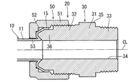
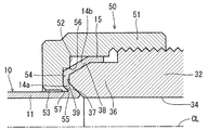
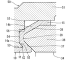
以下、本発明の実施の形態を図面に基づいて詳述する。図1は本発明の一実施の形態に係る管継手の断面図、図2は図1の要部拡大片側断面図、図3は図2の要部拡大図である。   Hereinafter, embodiments of the present invention will be described in detail with reference to the drawings. 1 is a cross-sectional view of a pipe joint according to an embodiment of the present invention, FIG. 2 is an enlarged cross-sectional side view of a main part of FIG. 1, and FIG. 3 is an enlarged view of the main part of FIG.

図1〜図3において、本実施形態の管継手20は、断面円形の流体移送路としての合成樹脂製のチューブ10をポンプ,バルブ,フィルタ等の流体機器に連通接続するもので、合成樹脂製の継手本体30と、同じく合成樹脂製のナット部材50の2部品で構成されている。   1 to 3, a pipe joint 20 according to the present embodiment connects a synthetic resin tube 10 as a fluid transfer path having a circular cross section to fluid devices such as a pump, a valve, and a filter. The joint body 30 and a nut member 50 made of synthetic resin are also used.

継手本体30とナット部材50の合成樹脂材料は、基本的にはチューブ10と同じ合成樹脂材料が用いられる。例えばPTEF(ポリテトラフルオロエチレン)、PFA(テトラフルオロエチレン・パーフルオロアルキルビニルエーテル共重合体)、ETFE(テトラフルオロエチレン・エチレン共重合体)、PVDF(ポリビニリデンフルオライド)等のフッ素樹脂、その他、PP(ポリプロピレン)、PEEK(ポリエーテルエーテルケトン)が用いられる。   The synthetic resin material for the joint body 30 and the nut member 50 is basically the same synthetic resin material as that for the tube 10. For example, PTFE (polytetrafluoroethylene), PFA (tetrafluoroethylene / perfluoroalkyl vinyl ether copolymer), ETFE (tetrafluoroethylene / ethylene copolymer), PVDF (polyvinylidene fluoride), and other fluororesins, PP (polypropylene) and PEEK (polyetheretherketone) are used.

図4はチューブの接続端部における初期状態の半断面図であり、管継手20を用いてチューブ10を接続対象としての流体機器に接続するに当たり、チューブ10の接続端部には、図4に示すように、予め、チューブ10の非拡径部11に連なる垂直段差部12及び該垂直段差部12に連なるテーパー段差部13を有する段差部14を経て、拡径した状態で継手本体50の後述するインナ筒部36に外嵌する直筒状の拡径部15を設けている。   FIG. 4 is a half sectional view of an initial state at the connection end of the tube. When the tube 10 is connected to a fluid device as a connection object using the pipe joint 20, the connection end of the tube 10 is shown in FIG. As shown in the drawing, the joint body 50 will be described later in a state in which the diameter is expanded in advance through a stepped portion 14 having a vertical stepped portion 12 connected to the non-diametered portion 11 of the tube 10 and a tapered stepped portion 13 connected to the vertical stepped portion 12. A straight cylindrical enlarged-diameter portion 15 that is fitted on the inner cylindrical portion 36 is provided.

拡径部15は、チューブ10の接続端部を、例えばチューブ拡径器を用いて常温下或いは加熱しながら段階的に拡径変形させることで設けることができる。   The expanded diameter portion 15 can be provided by expanding and deforming the connecting end portion of the tube 10 in a stepwise manner at room temperature or while heating, for example, using a tube expander.

継手本体30は、図1の紙面左右方向に一直線状に延びる水平な軸線(中心線)CLを有する直管部31と、該直管部31の左右端部より左右逆向きに該直管部31と同軸上で突出する2つの筒状の接続端部、つまり筒状のチューブ接続端部としての筒状の第1雄ネジ部32及び筒状の機器接続端部としての筒状の第2雄ねじ部33とを一体に形成し、第1雄ねじ部32側から直管部31を経て第2雄ねじ部33側に一直線状に貫通する流体移送路34を形成している。   The joint body 30 includes a straight pipe portion 31 having a horizontal axis (center line) CL extending linearly in the left-right direction in FIG. 1, and the straight pipe portion in the opposite direction from the left and right ends of the straight pipe portion 31. Two cylindrical connection ends projecting coaxially with 31, that is, a cylindrical first male screw portion 32 as a cylindrical tube connection end and a cylindrical second as a cylindrical device connection end The male threaded portion 33 is formed integrally, and a fluid transfer path 34 is formed that penetrates in a straight line from the first male threaded portion 32 side through the straight pipe portion 31 to the second male threaded portion 33 side.

継手本体30が形成する流体移送路34は、チューブ10が形成する流体移送路と略同じ直径を有する断面円形のものである。   The fluid transfer path 34 formed by the joint body 30 has a circular cross section having substantially the same diameter as the fluid transfer path formed by the tube 10.

直管部31は、第1雄ネジ部32及び第2雄ねじ部33の基部となる該直管部31の左右端部の外面よりそれぞれ別々に径方向外側に張り出す把持部35を設けている。該把持部35は、直管部31と同芯に形成されるとともに、その外面は6角等の多角形に形成されており、レンチ等の工具をかけることができる。   The straight pipe part 31 is provided with a grip part 35 that protrudes radially outward from the outer surfaces of the left and right end parts of the straight pipe part 31 that are the base parts of the first male screw part 32 and the second male screw part 33, respectively. . The grip portion 35 is formed concentrically with the straight pipe portion 31, and the outer surface thereof is formed in a polygon such as a hexagon, and a tool such as a wrench can be applied.

本実施形態では、第1雄ネジ部32及び第2雄ねじ部33の基部となる直管部31の左右端部が接近しているため、第1雄ネジ部32の基部と第2雄ねじ部33の基部にそれぞれ別々に設けられる把持部35は一つに繋がっている。   In this embodiment, since the left and right end portions of the straight pipe portion 31 that is the base portion of the first male screw portion 32 and the second male screw portion 33 are close to each other, the base portion of the first male screw portion 32 and the second male screw portion 33 are. The grip portions 35 that are separately provided at the base portions are connected to one.

第1雄ネジ部32は、該第1雄ねじ部32の先端部より該第1雄ねじ部32と同軸上でさらに軸方向に突出し、該第1雄ねじ部32の内径と同じ内径、該第1雄ねじ部32の外径より小径な外径を有し、チューブ10の拡径部15が外嵌する円筒状のインナ筒部36を設けている。   The first male screw portion 32 further protrudes in the axial direction coaxially with the first male screw portion 32 from the distal end portion of the first male screw portion 32, and has the same inner diameter as the inner diameter of the first male screw portion 32. A cylindrical inner tube portion 36 having an outer diameter smaller than the outer diameter of the portion 32 and into which the expanded diameter portion 15 of the tube 10 is fitted is provided.

該インナ筒部36には、該インナ筒部36の先端部内面側の角部を略45度の角度で斜めに落とすような第1テーパー部37を設けるとともに、該インナ筒部36の先端部外面側の角部を略30度の角度で斜めに落とすような第2テーパー部38を設けている。   The inner tube portion 36 is provided with a first taper portion 37 that drops the corner portion on the inner surface side of the tip portion of the inner tube portion 36 at an angle of approximately 45 degrees, and the tip portion of the inner tube portion 36 is provided. A second tapered portion 38 is provided so that the corner on the outer surface side is obliquely dropped at an angle of about 30 degrees.

本実施形態では、第1テーパー部37と第2テーパー部38の間に、インナ筒部36における軸線CLに垂直な平面内にある先端面を残したものである平坦部39を設けているが、平坦部39を設けることなく第1テーパー部37と第2テーパー部38を直接繋いでもよい。この場合、第1テーパー部37と第2テーパー部38の交点は角張らせてもよいし、多少の丸みを付けてもよい。要するに、インナ筒部36の先端部の片側断面形状を第1テーパー部37と第2テーパー部38で先細りの台形状や三角形状にしている。   In the present embodiment, a flat portion 39 is provided between the first taper portion 37 and the second taper portion 38, leaving a tip surface in a plane perpendicular to the axis CL in the inner cylinder portion 36. The first tapered portion 37 and the second tapered portion 38 may be directly connected without providing the flat portion 39. In this case, the intersection of the first taper portion 37 and the second taper portion 38 may be squared or slightly rounded. In short, the one-side cross-sectional shape of the front end portion of the inner cylinder portion 36 is formed into a tapered trapezoidal shape or a triangular shape by the first tapered portion 37 and the second tapered portion 38.

第2雄ねじ部33は、チューブ10の接続対象としての流体機器のチューブ接続口に設けられた相手方の雌ねじ部に螺合可能なものである。第2雄ねじ部33と相手方の雌ねじ部のねじは、シール性を発揮するテーパーねじである。   The second male screw portion 33 can be screwed into a mating female screw portion provided in a tube connection port of a fluid device as a connection target of the tube 10. The screw of the second male screw portion 33 and the counterpart female screw portion is a taper screw that exhibits sealing performance.

なお、第1テーパー部37は、継手本体30が形成する流体移送路34における第1雄ネジ部32側の開口縁、つまりインナ筒部36の先端面と内周面との角部を面取りし、チューブ10が形成する流体移送路と継手本体30が形成する流体移送路34との継ぎ目で液溜まりが発生するのを防止する機能を有する。   The first tapered portion 37 chamfers the opening edge on the first male screw portion 32 side in the fluid transfer path 34 formed by the joint main body 30, that is, the corner portion between the distal end surface and the inner peripheral surface of the inner cylindrical portion 36. The liquid transfer path formed by the tube 10 and the fluid transfer path 34 formed by the joint main body 30 have a function of preventing a liquid pool from being generated.

ナット部材50は、ねじ孔の一方が閉鎖された袋ナットにおけるねじ孔の奥側からチューブ10を挿入できるようにしたユニオンナットで成り、第1雄ネジ部32に螺合可能なナット部51と、該ナット部51のねじ孔の一方を閉鎖するよう該ナット部51の一端部(図1の左端部)から径方向内側に直角に延出され、ナット部51を第1雄ねじ部32に螺合したとき、ナット部材50のねじ軸、つまり軸線CLに垂直な平面内にあり、インナ筒部36の先端の平坦面39と軸方向で対向する端壁52と、該端壁52の中心部を開口する内外面貫通の円形なチューブ挿入孔53とを同軸上に一体に形成している。   The nut member 50 is a union nut that allows the tube 10 to be inserted from the back side of the screw hole in the cap nut in which one of the screw holes is closed, and a nut portion 51 that can be screwed into the first male screw portion 32. The nut portion 51 is extended perpendicularly inwardly from one end portion (left end portion in FIG. 1) of the nut portion 51 so as to close one of the screw holes of the nut portion 51, and the nut portion 51 is screwed to the first male screw portion 32. When assembled, an end wall 52 that is in a plane perpendicular to the screw shaft of the nut member 50, that is, the axis CL, and that is opposed to the flat surface 39 at the tip of the inner cylinder portion 36 in the axial direction, and the center portion of the end wall 52 And a circular tube insertion hole 53 penetrating the inner and outer surfaces is integrally formed on the same axis.

ナット部材50が形成するチューブ挿入孔53は、そこを挿通するチューブ10との間に僅かなクリアランスを設ける孔径を有しており、該クリアランスによりチューブ10がナット部材50と連れ回りするのを防止している。   The tube insertion hole 53 formed by the nut member 50 has a hole diameter that provides a slight clearance between the tube 10 and the tube 10 inserted therethrough, and the clearance prevents the tube 10 from rotating together with the nut member 50. is doing.

軸線CLに垂直な平面内にあり、ねじ孔の奥壁を形成する端壁52は、該端壁52を部分的に後退させる、該端壁と同芯な円環状の溝部54を設けている。該溝部54は、チューブ10の管壁の厚みと略同等かそれ以上の溝深を有するとともに、インナ筒部36の主内径(継手本体20が形成する流体移送路34の直径)より大径、かつ、端壁52の主内径(チューブ挿入孔53の直径≒チューブ10の非拡径部11の外径)より所定寸法だけ大径、かつ、平坦部39の内径より小径の内径、及び、インナ筒部36の主外径(第2テーパー部38以降のインナ筒部36の外径)より小径、かつ、平坦部39の外径より大径の外径を有しており、インナ筒部36の第1テーパー部37に対向する領域内と第2テーパー部38に対向する領域内それぞれに一つずつ段差を付けるものである。   An end wall 52 which is in a plane perpendicular to the axis CL and forms the inner wall of the screw hole is provided with an annular groove 54 concentric with the end wall, which partially retracts the end wall 52. . The groove portion 54 has a groove depth substantially equal to or greater than the thickness of the tube wall of the tube 10 and is larger in diameter than the main inner diameter of the inner cylinder portion 36 (the diameter of the fluid transfer path 34 formed by the joint body 20). In addition, an inner diameter that is larger by a predetermined dimension than the main inner diameter of the end wall 52 (the diameter of the tube insertion hole 53 ≈ the outer diameter of the non-expanded diameter portion 11 of the tube 10) and smaller than the inner diameter of the flat portion 39, and the inner The inner cylindrical portion 36 has an outer diameter smaller than the main outer diameter of the cylindrical portion 36 (the outer diameter of the inner cylindrical portion 36 after the second tapered portion 38) and larger than the outer diameter of the flat portion 39. One step is provided in each of the region facing the first tapered portion 37 and the region facing the second tapered portion 38.

そして、溝部54により端壁52に付けられた同芯な内外二つの段差部のうち、内側の段差部で該段差部を溝部54の奥側に向かって漸次縮径する第3テーパー部55を形成するとともに、外側の段差部で鋭角のエッジ部56を形成している。   Of the two concentric inner and outer stepped portions attached to the end wall 52 by the groove portion 54, a third taper portion 55 that gradually reduces the diameter of the stepped portion toward the inner side of the groove portion 54 at the inner step portion. At the same time, an acute edge portion 56 is formed at the outer stepped portion.

また、第3テーパー部55とチューブ挿入孔53の間に、端壁52より突出しないくさび状の片側断面形状を有する円形の押し輪部57を形成している。第3テーパー部55は第1テーパー部37と平行に形成することが好ましい。   A circular push ring portion 57 having a wedge-shaped one-side cross-sectional shape that does not protrude from the end wall 52 is formed between the third tapered portion 55 and the tube insertion hole 53. The third tapered portion 55 is preferably formed in parallel with the first tapered portion 37.

以上の構成において、チューブ10の接続端部を継手本体30に接続するには、チューブ10の接続端部を拡径加工する前に、該チューブ10の接続端部をナット部材50のチューブ挿入孔53に端壁52の外側より挿入し、ナット部材50をチューブ10に外嵌してからチューブ10の接続端部を拡径加工して非拡径部11より段差部14を経て拡径された拡径部15を設ける。そして、チューブ10の接続端部における最先端にある直筒状の拡径部15を継手本体30の第1雄ねじ部32に設けたインナ筒部36に外嵌した状態で、予めチューブ10に外嵌してあるナット部材50のナット部51を継手本体30の第1雄ねじ部32に螺合することにより完了する。   In the above configuration, in order to connect the connection end of the tube 10 to the joint body 30, the connection end of the tube 10 is connected to the tube insertion hole of the nut member 50 before the diameter of the connection end of the tube 10 is increased. 53, the nut member 50 was fitted to the tube 10 from the outside of the end wall 52, the diameter of the connecting end of the tube 10 was increased, and the diameter was increased from the non-expanded portion 11 through the stepped portion 14. An enlarged diameter portion 15 is provided. Then, the straight cylindrical enlarged diameter portion 15 at the forefront of the connection end of the tube 10 is externally fitted to the tube 10 in advance in a state where the inner cylindrical portion 36 provided in the first male screw portion 32 of the joint body 30 is externally fitted. This is completed by screwing the nut portion 51 of the nut member 50 to the first male screw portion 32 of the joint body 30.

即ち、ナット部材50のナット部51を継手本体30の第1雄ねじ部32に螺合することにより、チューブ10の非拡径部11より拡径部15にかかる該チューブ10の段差部14がインナ筒部36とナット部材50の端壁52との間に配置される。この状態で、ナット部材50を回しながらナット部51を継手本体30の第1雄ねじ部32の外面で軸線CLに沿って基部側に漸次螺進させると、端壁52がインナ筒部36に漸次接近し、端壁52の押し輪部57の尖端がチューブ10の非拡径部11より段差部14の垂直段差部12にかかる屈曲部に突き合い接触し、段差部14を押し、遂には垂直段差部12をインナ筒部36に平坦面39で突き合い接触させる。   That is, when the nut portion 51 of the nut member 50 is screwed into the first male screw portion 32 of the joint body 30, the stepped portion 14 of the tube 10 that extends from the non-diameter enlarged portion 11 of the tube 10 to the enlarged diameter portion 15 is changed to the inner portion. It arrange | positions between the cylinder part 36 and the end wall 52 of the nut member 50. FIG. In this state, when the nut portion 51 is gradually screwed to the base side along the axis CL on the outer surface of the first male screw portion 32 of the joint body 30 while turning the nut member 50, the end wall 52 gradually moves to the inner cylinder portion 36. Approaching, the tip of the push ring portion 57 of the end wall 52 abuts against and comes into contact with the bent portion of the vertical stepped portion 12 of the stepped portion 14 from the non-diametered portion 11 of the tube 10, pushes the stepped portion 14, and finally vertical The stepped portion 12 is brought into abutting contact with the inner cylindrical portion 36 on the flat surface 39.

この状態で、ナット部材50をさらに回してナット部51を継手本体30の第1雄ねじ部32の外面で軸線CLに沿って基部側に螺進させると、チューブ10の非拡径部11より段差部14の垂直段差部12にかかる屈曲部が押し輪部57の尖端でさらに押され、インナ筒部36の先端部内周に設けた第1テーパー部37の内側に押し込まれる。該押し輪部57の直ぐ外周の端壁52はそこに設けた溝部54で後退しているため、チューブ10の垂直段差部12は第1テーパー部37に沿って折り返された状態で、該第1テーパー部37と、端壁52に設けた溝部54で付けられた2つの段差部のうち、内側の段差部で形成した第3テーパー部55との間で強く挟持されるとともに、チューブ10の非拡径部11より折り返し部(折り返し前は段差部14の基部側である垂直段差部12)14aにかかる屈曲部に該チューブ10の挿入方向で係合するから、高いチューブ引き抜き強度を効果的に確保することができ、高いチューブ引き抜き強度でチューブ10の接続端部が継手本体30に接続される。   In this state, when the nut member 50 is further turned and the nut portion 51 is screwed to the base side along the axis CL on the outer surface of the first male screw portion 32 of the joint body 30, a step is formed from the non-diameter portion 11 of the tube 10. The bent portion of the vertical stepped portion 12 of the portion 14 is further pushed by the tip of the push ring portion 57 and is pushed into the first tapered portion 37 provided on the inner periphery of the distal end portion of the inner cylinder portion 36. Since the end wall 52 on the outer periphery of the push ring portion 57 is retracted by the groove portion 54 provided there, the vertical stepped portion 12 of the tube 10 is folded back along the first taper portion 37 in the state where the first step portion 52 is folded back. The first taper portion 37 and the third taper portion 55 formed by the inner step portion of the two step portions provided by the groove portion 54 provided in the end wall 52 are strongly sandwiched, and the tube 10 Since the tube 10 is engaged with the bent portion of the folded portion (vertical stepped portion 12 that is the base side of the stepped portion 14 before folding) 14a from the non-expanded portion 11 in the insertion direction of the tube 10, high tube pulling strength is effective. The connecting end portion of the tube 10 is connected to the joint body 30 with a high tube pulling strength.

また、端壁52に設けた溝部54で付けられた2つの段差部のうち、外側の段差部で形成したエッジ部56は、チューブ10の段差部14における垂直段差部12の外側部或いはそれに連なるテーパー段差部13をインナ筒部36の先端部外周に設けた第2テーパー部38に押し付ける。これにより、チューブ10の段差部14は折り返し部14aを経てインナ筒部36の第2テーパー部38に沿って折り戻され、エッジ部56でチューブ10の折り戻し部(折り戻し前は段差部14の先端側である垂直段差部12の外側部或いはテーパー段差部13)14bを第2テーパー部38に強く押し付けるから、そこでチューブ引き抜き強度をさらに高めながら、流体のシールに必要な面圧を効果的に発生し、流体の漏れを確実に防止した状態でチューブ10の接続端部が継手本体30に接続される。   Of the two step portions provided by the groove portion 54 provided in the end wall 52, the edge portion 56 formed by the outer step portion is connected to the outer portion of the vertical step portion 12 in the step portion 14 of the tube 10 or to the outer step portion. The tapered step portion 13 is pressed against a second tapered portion 38 provided on the outer periphery of the tip end portion of the inner cylinder portion 36. As a result, the stepped portion 14 of the tube 10 is folded back along the second tapered portion 38 of the inner cylindrical portion 36 via the folded portion 14a, and the folded portion of the tube 10 at the edge portion 56 (the stepped portion 14 before folding). Since the outer portion of the vertical step portion 12 or the taper step portion 13) 14b which is the front end side of the tube is strongly pressed against the second taper portion 38, the surface pressure required for fluid sealing is effectively increased while further increasing the tube pulling strength. The connection end of the tube 10 is connected to the joint body 30 in a state where the leakage of fluid is reliably prevented.

以上、本実施の形態は、本発明に係る管継手の好適な一実施の形態をチューブ10を流体機器のチューブ接続口にストレートに接続する管継手20で説明したが、本発明はそれに限定されることなく、その要旨を逸脱しない範囲内で種々変形実施することができる。例えばチューブ10同士を接続するエルボ,チーズ,クロス等の管継手に実施することができ、この場合は、図1の把持部35より左側のチューブ接続構造がエルボ,チーズ,クロス等の継手本体の管部の端部に設けられる。   As mentioned above, although this Embodiment demonstrated one suitable embodiment of the pipe joint which concerns on this invention with the pipe joint 20 which connects the tube 10 straight to the tube connection port of a fluid apparatus, this invention is limited to it. Without departing from the spirit of the present invention, various modifications can be made. For example, it can be applied to pipe joints such as elbows, cheeses, and crosses that connect the tubes 10 to each other. In this case, the tube connection structure on the left side of the grip portion 35 in FIG. Provided at the end of the tube.

また、管継手20を用いてチューブ10を接続対象に接続するにあたり、チューブ10の接続端部に、予め、非拡径部11より垂直段差部12とテーパー段差部13を経て拡径された拡径部15を設けたが、チューブ10の管壁の厚みによっては、例えば非拡径部11よりテーパー段差部13のみを経て拡径された拡径部15を設けるだけでも、図1〜図3に示す状態でチューブ10の接続端部を継手本体30の第1雄ネジ部32に接続することができる。従って、チューブの接続端部における初期形状は、チューブ10の材質や管壁の厚み及び施工性を考慮して適宜設定されるものであり、接続後のチューブ10の接続端部形状(折り返し部14a及び折り戻し部14bと拡径部15)と同じ形状を与える必要はない。   Further, when the tube 10 is connected to the connection target using the pipe joint 20, the connection end of the tube 10 is expanded in advance from the non-diameter portion 11 through the vertical step portion 12 and the taper step portion 13. Although the diameter portion 15 is provided, depending on the thickness of the tube wall of the tube 10, for example, even if only the diameter-expanded portion 15 that is expanded from the non-diameter-expanded portion 11 through only the tapered step portion 13 is provided, FIGS. The connection end of the tube 10 can be connected to the first male screw portion 32 of the joint body 30 in the state shown in FIG. Accordingly, the initial shape at the connection end of the tube is appropriately set in consideration of the material of the tube 10, the thickness of the tube wall, and workability, and the connection end shape of the tube 10 after connection (the folded portion 14 a). It is not necessary to give the same shape as the folded portion 14b and the enlarged diameter portion 15).

また、本実施の形態では、シール用のエッジ部56を一つしか設けていないが、図5に示すように、複数設けることもできる。   In this embodiment, only one sealing edge 56 is provided, but a plurality of sealing edges 56 may be provided as shown in FIG.

図5は本発明の他の実施の形態に係る管継手の要部拡大断面図である。図5に示す管継手21は、ナット部材50の端壁52に設けた溝部54で付けられた2つの段差部のうち、外側の段差部で形成したエッジ部56の周囲に、該エッジ部56と同様にチューブ10の折り戻し部14bを第2テーパー部38に強く押し付ける、該エッジ部56と同芯な他のエッジ部56aを設けた点が、図1に示した管継手20と異なるだけであり、その他の構造は同じである。本実施形態では、チューブ10の折り戻し部14bを鋸刃状の多段エッジ(多重エッジ)で第2テーパー部38に強く押し付けるから、チューブ10の耐引き抜き性能及びシール性能は図1に示した管継手20に比べさらに高くなる。   FIG. 5 is an enlarged sectional view of a main part of a pipe joint according to another embodiment of the present invention. The pipe joint 21 shown in FIG. 5 has an edge portion 56 around the edge portion 56 formed by the outer step portion of the two step portions provided by the groove portion 54 provided in the end wall 52 of the nut member 50. 1 is different from the pipe joint 20 shown in FIG. 1 only in that the folded portion 14b of the tube 10 is strongly pressed against the second tapered portion 38, and another edge portion 56a concentric with the edge portion 56 is provided. The other structures are the same. In this embodiment, since the folded portion 14b of the tube 10 is strongly pressed against the second tapered portion 38 with a saw blade-like multi-stage edge (multiple edge), the tube 10 shown in FIG. It becomes higher than the joint 20.

本発明の一実施の形態に係る管継手の断面図である。It is sectional drawing of the pipe joint which concerns on one embodiment of this invention. 図1の要部拡大片側断面図である。It is a principal part expanded one side sectional view of FIG. 図2の要部拡大図である。FIG. 3 is an enlarged view of a main part of FIG. 2. チューブの接続端部における初期状態の半断面図である。It is a half sectional view of the initial state in the connection end part of a tube. 本発明の他の実施の形態に係る管継手の要部拡大断面図である。It is a principal part expanded sectional view of the pipe joint which concerns on other embodiment of this invention.

符号の説明Explanation of symbols

10 チューブ
14 段差部
14a 折り返し部
14b 折り戻し部
15 拡径部
20 管継手
30 継手本体
32 第1雄ネジ部(チューブ接続端部)
36 インナ筒部
37 第1テーパー部
38 第2テーパー部
50 ナット部材
51 ナット部
52 端壁
54 溝部
55 第3テーパー部
56 エッジ部
56a エッジ部
57 押し輪部
DESCRIPTION OF SYMBOLS 10 Tube 14 Step part 14a Folding part 14b Folding part 15 Expanded part 20 Pipe joint 30 Joint main body 32 First male thread part (tube connection end part)
36 Inner cylinder part 37 1st taper part 38 2nd taper part 50 Nut member 51 Nut part 52 End wall 54 Groove part 55 3rd taper part 56 Edge part 56a Edge part 57 Push ring part

Claims (2)

少なくとも一つの端部に筒状のチューブ接続端部を設けた筒状の継手本体と、該継手本体のチューブ接続端部に接続すべき合成樹脂製のチューブに外嵌され、前記チューブ接続端部に螺合されるナット部材を有し、前記継手本体と前記ナット部材それぞれが合成樹脂で形成され、前記チューブ接続端部が該チューブ接続端部よりさらに軸方向に突出して前記チューブの接続端部が拡径した状態で外嵌するインナ筒部を設け、該インナ筒部が該インナ筒部の先端部内外面にテーパー部を設け、前記ナット部材が該ナット部材のねじ孔の奥側にねじ軸に垂直な端壁を設けるとともに、該端壁に前記チューブを端壁側からねじ孔内に挿入するチューブ挿入孔を設け、前記端壁が前記インナ筒部の内径より大径の内径と前記インナ筒部の外径より小径の外径を有して該端壁を部分的に後退させる環状の溝部を設け、該溝部により前記端壁に付けられる内外二つの段差部のうち、内側の段差部で該段差部を前記溝部の奥側に向かって漸次縮径するテーパー部を形成するとともに、外側の段差部でエッジ部を形成したことを特徴とする管継手。   A tubular joint body provided with a tubular tube connection end at at least one end, and a tube made of synthetic resin to be connected to the tube connection end of the joint body, the tube connection end Each of the joint body and the nut member is made of a synthetic resin, and the tube connection end protrudes further in the axial direction from the tube connection end. An inner cylinder part that fits outside in a state in which the diameter of the inner cylinder part is fitted is provided, the inner cylinder part is provided with a taper part on the inner and outer surfaces of the distal end part of the inner cylinder part, and the nut member is a screw shaft on the inner side of the screw hole of the nut member. An end wall perpendicular to the inner wall and a tube insertion hole for inserting the tube into the screw hole from the end wall side. The inner diameter of the end wall is larger than the inner diameter of the inner cylindrical portion and the inner wall. Smaller than the outer diameter of the tube An annular groove having an outer diameter and partially retracting the end wall is provided, and of the two inner and outer stepped portions attached to the end wall by the groove, the stepped portion is formed on the inner stepped portion. A pipe joint characterized in that a tapered portion that gradually decreases in diameter toward the back side is formed, and an edge portion is formed at an outer stepped portion. 前記継手本体と前記ナット部材それぞれがフッ素樹脂で形成されている請求項1に記載の管継手。   The pipe joint according to claim 1, wherein each of the joint body and the nut member is formed of a fluororesin.
JP2008202361A 2008-08-05 2008-08-05 Pipe fitting Expired - Fee Related JP4625856B2 (en)

Priority Applications (1)

Application Number Priority Date Filing Date Title
JP2008202361A JP4625856B2 (en) 2008-08-05 2008-08-05 Pipe fitting

Applications Claiming Priority (1)

Application Number Priority Date Filing Date Title
JP2008202361A JP4625856B2 (en) 2008-08-05 2008-08-05 Pipe fitting

Publications (2)

Publication Number Publication Date
JP2010038261A true JP2010038261A (en) 2010-02-18
JP4625856B2 JP4625856B2 (en) 2011-02-02

Family

ID=42011028

Family Applications (1)

Application Number Title Priority Date Filing Date
JP2008202361A Expired - Fee Related JP4625856B2 (en) 2008-08-05 2008-08-05 Pipe fitting

Country Status (1)

Country Link
JP (1) JP4625856B2 (en)

Citations (1)

* Cited by examiner, † Cited by third party
Publication number Priority date Publication date Assignee Title
JPH10299964A (en) * 1997-04-23 1998-11-13 Furoueru:Kk Joint for tube member

Patent Citations (1)

* Cited by examiner, † Cited by third party
Publication number Priority date Publication date Assignee Title
JPH10299964A (en) * 1997-04-23 1998-11-13 Furoueru:Kk Joint for tube member

Also Published As

Publication number Publication date
JP4625856B2 (en) 2011-02-02

Similar Documents

Publication Publication Date Title
TWI616609B (en) Pipe connection
WO2010016363A1 (en) Tube joint consisting of resin
JP5873833B2 (en) Pipe connection device
EP3001086B1 (en) Pipe connecting device
WO2014181589A1 (en) Inner ring
JP4751920B2 (en) Resin pipe fitting
JP4625855B2 (en) Pipe fitting
JP4625856B2 (en) Pipe fitting
JP2010133450A (en) Resin pipe joint
JP2010038259A (en) Pipe joint
JP2010038268A (en) Resin pipe joint
JP5055222B2 (en) Resin pipe fitting
JP4963688B2 (en) Resin pipe fitting
JP4963689B2 (en) Resin pipe fitting
JP6040294B2 (en) Pipe connection device
JP5171467B2 (en) Resin pipe fitting
JP2010038270A (en) Resin pipe joint
JP2010038260A (en) Pipe joint
JP5142878B2 (en) Resin pipe fitting
JP2010223291A (en) Resin pipe joint
JP5112216B2 (en) Resin pipe fitting
JP5210756B2 (en) Resin pipe fitting
JP4982447B2 (en) Resin pipe fitting
JP2010038269A (en) Resin pipe joint
JP5690553B2 (en) Resin pipe joint assembly structure and resin pipe joint assembly method

Legal Events

Date Code Title Description
A621 Written request for application examination

Free format text: JAPANESE INTERMEDIATE CODE: A621

Effective date: 20100226

TRDD Decision of grant or rejection written
A01 Written decision to grant a patent or to grant a registration (utility model)

Free format text: JAPANESE INTERMEDIATE CODE: A01

Effective date: 20101102

A977 Report on retrieval

Free format text: JAPANESE INTERMEDIATE CODE: A971007

Effective date: 20101029

A01 Written decision to grant a patent or to grant a registration (utility model)

Free format text: JAPANESE INTERMEDIATE CODE: A01

A61 First payment of annual fees (during grant procedure)

Free format text: JAPANESE INTERMEDIATE CODE: A61

Effective date: 20101108

R150 Certificate of patent or registration of utility model

Free format text: JAPANESE INTERMEDIATE CODE: R150

FPAY Renewal fee payment (event date is renewal date of database)

Free format text: PAYMENT UNTIL: 20131112

Year of fee payment: 3

LAPS Cancellation because of no payment of annual fees