JP2010038073A - Intake air control device for internal combustion engine - Google Patents
Intake air control device for internal combustion engine Download PDFInfo
- Publication number
- JP2010038073A JP2010038073A JP2008203355A JP2008203355A JP2010038073A JP 2010038073 A JP2010038073 A JP 2010038073A JP 2008203355 A JP2008203355 A JP 2008203355A JP 2008203355 A JP2008203355 A JP 2008203355A JP 2010038073 A JP2010038073 A JP 2010038073A
- Authority
- JP
- Japan
- Prior art keywords
- intake
- volume
- throttle valve
- engine
- internal combustion
- Prior art date
- Legal status (The legal status is an assumption and is not a legal conclusion. Google has not performed a legal analysis and makes no representation as to the accuracy of the status listed.)
- Granted
Links
Images


Classifications
-
- Y—GENERAL TAGGING OF NEW TECHNOLOGICAL DEVELOPMENTS; GENERAL TAGGING OF CROSS-SECTIONAL TECHNOLOGIES SPANNING OVER SEVERAL SECTIONS OF THE IPC; TECHNICAL SUBJECTS COVERED BY FORMER USPC CROSS-REFERENCE ART COLLECTIONS [XRACs] AND DIGESTS
- Y02—TECHNOLOGIES OR APPLICATIONS FOR MITIGATION OR ADAPTATION AGAINST CLIMATE CHANGE
- Y02T—CLIMATE CHANGE MITIGATION TECHNOLOGIES RELATED TO TRANSPORTATION
- Y02T10/00—Road transport of goods or passengers
- Y02T10/10—Internal combustion engine [ICE] based vehicles
- Y02T10/12—Improving ICE efficiencies
Landscapes
- Characterised By The Charging Evacuation (AREA)
- Control Of Throttle Valves Provided In The Intake System Or In The Exhaust System (AREA)
Abstract
Description
本発明は、内燃機関の吸気制御装置に関する。 The present invention relates to an intake control device for an internal combustion engine.
車両用エンジン(内燃機関)の吸気管には、エンジンの気筒毎に独立したスロットルバルブを備える独立吸気管方式のものと、複数の気筒につながる分岐形状を有するインテークマニホールドにスロットルバルブを備えるインテークマニホールド方式のものとがある。
独立吸気管方式は、エンジンの吸気弁とスロットルバルブとの間の吸気容積をインテークマニホールド方式に比べて小さくできるため、スロットル応答性や高比出力性能が要求される自動二輪車用エンジンに採用されており、特に高速・高出力エンジン程その傾向が強い。例えば、独立吸気管方式の自動二輪車用エンジンでは、インテークマニホールド方式を採用した同排気量の四輪車用エンジンに比して、吸気容積が約1/5〜1/10程度とされている。
また、この種の自動二輪車用エンジンには、エンジンの吸気通路に、インテークチャンバを接続すると共に、このインテークチャンバと吸気通路との接続部分にロータリーバルブを設け、吸気通路内の混合気の圧力変動を緩和して吸気効率を向上させ、エンジン出力向上とエンジンレスポンス向上を図るものが提案されている(例えば、特許文献1参照)。
The independent intake pipe system can reduce the intake volume between the intake valve and the throttle valve of the engine compared to the intake manifold system, so it is used in motorcycle engines that require throttle response and high specific output performance. The tendency is especially strong for high-speed and high-power engines. For example, an independent intake pipe type motorcycle engine has an intake volume of about 1/5 to 1/10 as compared to a four-wheeled vehicle engine of the same displacement employing an intake manifold system.
In addition, in this type of motorcycle engine, an intake chamber is connected to an intake passage of the engine, and a rotary valve is provided at a connection portion between the intake chamber and the intake passage to change the pressure of the air-fuel mixture in the intake passage. Has been proposed to improve the intake efficiency by improving the intake efficiency and improve the engine output and the engine response (see, for example, Patent Document 1).
ところで、近年、燃費向上とエミッション低減の要求が高まっている。
しかしながら、従来の吸気容積を小さくした自動二輪車用エンジンでは、安定したアイドルを行うために混合気濃度を濃いめにする必要があり、燃費向上に不利であり、かつ、後処理で排気を浄化するには二次空気を導入する二次空気導入装置が必要になってしまう。
また、特許文献1記載の構成は、エンジン出力向上とエンジンレスポンス向上とを図るために吸気容積を増大するものであり、燃費向上とエミッション低減とを図るものではない。しかも、この特許文献1の構成は、バルブ制御を行う分、構成および制御が煩雑になってしまう問題もあった。
By the way, in recent years, demands for improving fuel consumption and reducing emissions have increased.
However, in a conventional motorcycle engine with a small intake volume, it is necessary to increase the concentration of the air-fuel mixture in order to perform stable idling, which is disadvantageous for improving fuel efficiency and purifying exhaust gas in post-processing. Requires a secondary air introduction device for introducing secondary air.
In addition, the configuration described in
本発明は、上述した事情を鑑みてなされたものであり、燃費向上とエミッション低減に好適な内燃機関の吸気制御装置を提供することを目的としている。 The present invention has been made in view of the above-described circumstances, and an object thereof is to provide an intake control device for an internal combustion engine suitable for improving fuel consumption and reducing emissions.
上述課題を解決するため、本発明は、燃焼室に連通する吸気通路に吸気絞り弁を設けた内燃機関の吸気制御装置において、前記吸気絞り弁が所定開度以下のとき、前記吸気絞り弁の下流側吸気通路に内燃機関が低負荷低回転時に連通するように成した吸気チャンバを設け、前記吸気チャンバの容積は、少なくとも前記吸気絞り弁下流の吸気管容積との合算容積が行程容積の60%以上となる容積であることを特徴とする。
この構成によれば、吸気絞り弁が所定開度以下のとき、吸気絞り弁の下流側吸気通路に内燃機関が低負荷低回転時に連通するように成した吸気チャンバを設け、吸気チャンバの容積は、少なくとも吸気絞り弁下流の吸気管容積との合算容積が行程容積の60%以上となる容積であるため、二次空気導入装置を廃止可能な程度まで希薄混合気に対する燃焼を改善でき、燃費向上とエミッション低減を図ることができる。
In order to solve the above-mentioned problems, the present invention provides an intake control device for an internal combustion engine in which an intake throttle valve is provided in an intake passage communicating with a combustion chamber. An intake chamber is provided in the downstream intake passage so that the internal combustion engine communicates at low load and low rotation. The intake chamber has a volume that is at least the sum of the intake pipe volume downstream of the intake throttle valve and a stroke volume. % Of the volume or more.
According to this configuration, when the intake throttle valve is equal to or smaller than the predetermined opening, the intake chamber is provided in the downstream intake passage of the intake throttle valve so that the internal combustion engine communicates at low load and low rotation. Since the combined volume with at least the intake pipe volume downstream of the intake throttle valve is 60% or more of the stroke volume, the combustion of the lean air-fuel mixture can be improved to the extent that the secondary air introduction device can be abolished, and the fuel efficiency can be improved. And reduce emissions.
上記構成において、前記吸気チャンバの容積は、前記吸気絞り弁下流の吸気管容積の少なくとも1倍以上の容積を有するようにしてもよい。この構成によれば、このエンジンを従来の自動二輪車用エンジンと同様に吸気通路を小さくした場合でも、吸気チャンバの容積を、少なくとも吸気絞り弁下流の吸気管容積との合算容積が行程容積の60%以上となる容積にすることができる。 In the above configuration, the volume of the intake chamber may have a volume that is at least one time larger than the intake pipe volume downstream of the intake throttle valve. According to this configuration, even when the intake passage of the engine is reduced as in the case of a conventional motorcycle engine, the volume of the intake chamber, at least the sum of the intake pipe volume downstream of the intake throttle valve, is 60% of the stroke volume. % Or more.
また、上記構成において、前記吸気通路と、この吸気通路が連通する気筒とは別の気筒に連通する吸気通路とを前記内燃機関の低負荷低回転時に連通させる切換弁を設け、この切換弁を介して連通させた前記別の気筒の吸気通路を前記吸気チャンバの代用としてもよい。この構成によれば、吸気行程ではない気筒側の吸気通路を吸気チャンバに代用でき、吸気チャンバを別途設ける場合に比して、小型化できる。 Further, in the above configuration, a switching valve is provided that connects the intake passage and an intake passage that communicates with a cylinder other than the cylinder that communicates with the intake passage at the time of low load and low rotation of the internal combustion engine. An intake passage of the other cylinder communicated with the intake chamber may be substituted for the intake chamber. According to this configuration, the intake passage on the cylinder side that is not the intake stroke can be substituted for the intake chamber, and the size can be reduced as compared with the case where the intake chamber is separately provided.
また、上記構成において、前記吸気チャンバは、前記吸気絞り弁により開閉される開閉通路を介して前記吸気絞り弁の下流側吸気通路に連通するようにしてもよい。この構成によれば、吸気絞り弁を吸気チャンバの開閉機構に兼用させることができ、部品点数の低減が可能になる。 In the above configuration, the intake chamber may be communicated with an intake passage downstream of the intake throttle valve via an opening / closing passage that is opened and closed by the intake throttle valve. According to this configuration, the intake throttle valve can also be used as an intake chamber opening / closing mechanism, and the number of parts can be reduced.
本発明では、吸気絞り弁が所定開度以下のとき、吸気絞り弁の下流側吸気通路に内燃機関が低負荷低回転時に連通するように成した吸気チャンバを設け、吸気チャンバの容積は、少なくとも吸気絞り弁下流の吸気管容積との合算容積が行程容積の60%以上となる容積であるため、燃費向上とエミッション低減を図ることができる。 In the present invention, when the intake throttle valve is below a predetermined opening, an intake chamber is provided in the intake passage downstream of the intake throttle valve so as to communicate with the internal combustion engine during low load and low rotation, and the volume of the intake chamber is at least Since the combined volume with the intake pipe volume downstream of the intake throttle valve is a volume that is 60% or more of the stroke volume, it is possible to improve fuel consumption and reduce emissions.
以下、本発明の一実施形態を添付した図面を参照して説明する。
<第一実施形態>
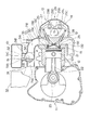
図1は、本発明の第一実施形態に係る自動二輪車用エンジンを吸気系と共に示す図である。図1において、符号10は、自動二輪車用エンジン(内燃機関)である。この自動二輪車用エンジン(以下、単にエンジンという)10は、クランクケース11と、シリンダブロック12と、シリンダヘッド13と、ヘッドカバー14とを備え、シリンダブロック12に一つのシリンダ室(気筒)12Aを備えた4サイクル単気筒エンジンである。
シリンダブロック12のシリンダ室12Aには、ピストン21が摺動自在に収容され、クランクケース11には、このピストン21にコンロッド22を介して連結されたクランクシャフト23が回転自在に軸支されている。また、クランクケース11には、図示は省略するが、クラッチ機構、変速機構及びエンジン10の出力軸等が収容される。
Hereinafter, an embodiment of the present invention will be described with reference to the accompanying drawings.
<First embodiment>
FIG. 1 is a view showing a motorcycle engine according to a first embodiment of the present invention together with an intake system. In FIG. 1,
A
シリンダヘッド13には、シリンダ室12A及びピストン21と共に燃焼室15を形成する凹部13Aが形成され、この凹部13Aには、シリンダヘッド13の吸気口13Bから延びる吸気ポート13Cを燃焼室15に連通させる吸気側開口部25と、シリンダヘッド13の排気口13Dから延びる排気ポート13Eを燃焼室15に連通させる排気側開口部26とが形成される。また、このシリンダヘッド13には、吸気側開口部25を開閉する吸気バルブ27と、排気側開口部26を開閉する排気バルブ28と、各バルブ27、28を駆動する動弁機構29とが配設される。
動弁機構29は、吸気工程、圧縮工程、燃焼工程及び排気工程の4工程のサイクルを実施するようにクランクシャフト23の回転に合わせて各バルブ27、28を駆動するものであり、吸気バルブ27及び排気バルブ28の間に回転自在に支持されるカムシャフト29Aと、このカムシャフト29Aに設けられたカム29B、29Cにより各々揺動される吸気側と排気側のロッカーアーム29D、29Eとを備えている。なお、動弁機構29は、このロッカーアーム方式に限らず、カムで直接各バルブ27、28を押動する直動方式等の他の構成を適用してもよい。
また、シリンダヘッド13には、点火プラグ(不図示)がその先端を燃焼室15に臨ませて取り付けられ、この点火プラグが図示せぬ点火装置(イグニッションコイル)を介して点火制御される。
The
The
An ignition plug (not shown) is attached to the
エンジン10の吸気口13Bには、吸気管30を介してスロットルボディ31が接続され、このスロットルボディ31の上流側(空気吸入口側)にはエアクリーナ32が接続される。
スロットルボディ31は、吸気管30と共にエンジン10への吸気通路を形成するものであり、本構成ではスロットルボディ31に吸気管30が一体に形成されている。このスロットルボディ31は、その内部にスロットルバルブ(吸気絞り弁)51を備え、このスロットルバルブ51を、回動軸52を支点にして回動させることで吸気通路を開閉し、これによって、エアクリーナ32からエンジン10内に供給される吸入空気量を可変する。
また、スロットルボディ31のスロットルバルブ51下流には、インジェクタ(燃料噴射装置)33を取り付けるためのインジェクタ取付部53が設けられ、このインジェクタ取付部53に、インジェクタ33がその先端を吸気ポート13Cに向けて挿入固定される。このインジェクタ33には、自動二輪車に搭載された燃料タンク内の燃料が燃料ポンプにより供給され、図示せぬ制御装置の制御によって燃料を噴射する。これによって、スロットルボディ31からは燃料と空気を混合した混合気がエンジン10に向けて供給される。
A
The
Further, an
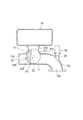
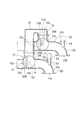
図2はスロットルボディ31を周辺構成と共に示している。この図に示すように、スロットルボディ31には、スロットルバルブ51を介してエンジン10への吸気通路(吸気管30に相当)に連通自在な箱状の吸気チャンバ61が設けられている。
詳述すると、このスロットルボディ31には、エンジン10への吸気通路を形成するスロットルボディケース(以下、ケースという。)31Aから突出するパイプ部(開閉通路)31Bが一体に形成され、このパイプ部31Bの先端に所定の空間容積を有する吸気チャンバ61が連結されている。
また、スロットルバルブ51は、このパイプ部31Bの端部31Cの開口を開閉自在に配置されている。具体的には、このスロットルバルブ51は、側面視で、略半月断面を有するバルブ体51Aを備え、このバルブ体51Aが回動軸52を支点に回動自在に支持される。ここで、図2には、バルブ体51Aの外周面51Bの移動軌跡を符号αで示しており、パイプ部31Bにおけるケース31A側の端部31Cの内周面は、この符号αで示すバルブ体51Aの移動軌跡に沿った曲面に形成されている。すなわち、このバルブ体51Aがパイプ部31Bの端部31Cの内周面に接触しながら回動することで、このバルブ体51Aとパイプ部31Bとの接触部分が殆ど隙間のない接触状態を保持するように構成されている。
FIG. 2 shows the
More specifically, the
Further, the
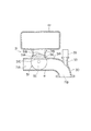
上記スロットルバルブ51は、運転者によるアクセル操作に応じて図2に示す位置から図3に示す位置まで回転する。より具体的には、図2がスロットルバルブ51を閉じた状態(無負荷で運転を継続するアイドル状態)を示しており、図3がスロットルバルブ51を開けた状態(全開状態)を示している。
すなわち、スロットルバルブ51を閉じた場合、図2に示すように、スロットルバルブ51のバルブ体51Aが、エンジン10への吸気通路を略閉塞するように回動軸52よりも上流側に位置し、エアクリーナ32からの空気がアイドルを維持可能な最小量に抑えられる。この場合、バルブ体51Aは、吸気チャンバ61とスロットルバルブ51上流側の吸気通路(以下、上流側吸気通路という。)71Aとの間の隙間は閉塞するが、吸気チャンバ61とスロットルバルブ51下流側の吸気通路(以下、下流側吸気通路という。)71Bとの間は連通させる。
これによって、スロットルバルブ51が閉じられてエンジン10が低負荷低回転時の場合、スロットルバルブ51下流側の吸気容積が、吸気チャンバ61の容積分だけ増大し、つまり、下流側吸気通路71Bの容積(吸気管容積)と吸気チャンバ61の容積とを加算した容積に増大させる。
The
That is, when the
As a result, when the
一方、スロットルバルブ51が全開の場合、図3に示すように、スロットルバルブ51のバルブ体51Aが、パイプ部31B側へ移動して上流側吸気通路71Aと下流側吸気通路71Bとを大開口で連通させる。この場合、バルブ体51Aは、パイプ部31Bの端部31Cの内周面の全周に亘って接触してパイプ部31Bを完全に閉じ、吸気チャンバ61とエンジン10への吸気通路との間の連通を完全遮断する。また、バルブ体51Aは、パイプ部31B内に完全に入り、しかも、このバルブ体51Aの内周面51Cが、スロットルバルブ51の上流側吸気通路71Aと下流側吸気通路71Bとの間を段差や凹凸なく連通させる三次元形状に形成されるので、上流側吸気通路71Aから下流側吸気通路71Bへかけて吸気抵抗を低減した大開口の吸気通路にすることができる。
このようにして、スロットルバルブ51を開けた状態(全開状態)では、スロットルバルブ51により吸気チャンバ61を切り離し、スロットルバルブ51の下流側吸気容積を減少させることができる。
On the other hand, when the
In this way, when the
次に、エンジン10の吸気容積について説明する。
一般に、自動二輪車用エンジンでは、スロットル応答性や高比出力性能が要求されるため、四輪車用エンジンに比して吸気容積が小さく形成されている。
しかし、発明者等の検討によれば、吸気容積が小さいと低負荷低回転時に、吸気通路内の負圧が十分に高まらず(吸気通路内のガス密度が大きく)、同質量の新気を吸入する場合の吸気バルブ通過速度が低くなってしまう。
タンブル/スワール等の燃焼室15内の混合気の流れ(つまり、筒内乱れ)の源をなす吸入流れの運動エネルギーは、流入質量と速度の二乗の積に比例するので、吸気容積が小さいエンジンでは、低負荷低回転時に筒内乱れが極端に弱まり、着火遅れが増加し、燃焼速度が著しく低下してしまうと考えられる。
Next, the intake volume of the
In general, a motorcycle engine is required to have a throttle response and a high specific output performance, and therefore has a smaller intake volume than a four-wheeled vehicle engine.
However, according to the study by the inventors, when the intake volume is small, the negative pressure in the intake passage does not sufficiently increase (the gas density in the intake passage is large) at low load and low rotation, and the same mass of fresh air is generated. The intake valve passing speed when inhaling is lowered.
An engine having a small intake volume because the kinetic energy of the intake flow that forms the source of the flow of the air-fuel mixture in the
この点についてシミュレーションを行った。図4はシミュレーションモデルを説明する図であり、図5及び図6はシミュレーション結果を示している。なお、図4中、符号71Cがスロットルバルブ51の下流側吸気通路を示している。
このシミュレーションでは、下流側吸気通路71Cが小容積の場合(従来の自動二輪車相当(0.25L(リットル))と、大容積の場合(本例では1.25L)とについて比較検討した。また、その他の条件は、エンジン回転数Neが1000rpm/min、空燃比が理想空燃比(ストイキオメトリー)、平均有効圧IMEPが150kPa、及び、単気筒650ccである。
A simulation was performed on this point. FIG. 4 is a diagram for explaining a simulation model, and FIGS. 5 and 6 show simulation results. In FIG. 4, reference numeral 71 </ b> C indicates a downstream side intake passage of the
In this simulation, the case where the downstream
図5は吸気行程及び圧縮行程の筒内圧Pcの変化を示している。ここで、図5の縦軸が筒内圧Pcを示し、横軸は、燃焼室15の容積比Vs(燃焼室15の容積Vs1/行程容積Vc)を示している。
図5に示すように、下流側吸気通路71Cが大容積の場合(実線で示す特性曲線f1A参照)、下流側吸気通路71Cが小容積の場合(二点鎖線で示す特性曲線f2A参照)に比して、吸気行程の開始当初から筒内圧Pcが低く、かつ、この筒内圧Pcの吸気行程終了までの変動量が小さくなることが判る。すなわち、吸気行程の平均圧が低くなることが判る。
また、図6は吸気行程の吸気流速Uiの変化を示している。ここで、図6の縦軸が吸気流速Uiを示し、横軸がクランク角度(ADTC(ピストン上死点後)の角度)を示している。この図に示すように、下流側吸気通路71Cが大容積の場合(実線で示す特性曲線f1B参照)には、下流側吸気通路71Cが小容積の場合(二点鎖線で示す特性曲線f2B参照)に比して、吸気流速Uiが高くなり、吸気行程の平均流速が高くなることが判る。
FIG. 5 shows changes in the in-cylinder pressure Pc during the intake stroke and the compression stroke. Here, the vertical axis in FIG. 5 represents the in-cylinder pressure Pc, and the horizontal axis represents the volume ratio Vs of the combustion chamber 15 (volume Vs1 / stroke volume Vc of the combustion chamber 15).
As shown in FIG. 5, compared to the case where the downstream
FIG. 6 shows a change in the intake air flow velocity Ui in the intake stroke. Here, the vertical axis in FIG. 6 indicates the intake air flow velocity Ui, and the horizontal axis indicates the crank angle (ADTC (angle after piston top dead center)). As shown in this figure, when the downstream
この図5及び図6によれば、下流側吸気通路71Cを大容積にすることで、吸気行程での筒内圧Pcを低くすることができ、この筒内圧Pcを低くすることで負圧(吸気通路内負圧)を高め(ガス密度を低くし)、吸気流速Ui(吸気バルブ通過速度に相当)を高くできることが明らかである。これにより、タンブル/スワール等の筒内乱れを適切に発生させることができると共に、燃焼室15への混合気の充填効率も高めることができる。このことは、図5に示すように、下流側吸気通路71Cが大容積の場合の方が、圧縮行程時に筒内圧Pcが高くなることからも明らかである。
According to FIGS. 5 and 6, the cylinder intake pressure Pc in the intake stroke can be reduced by increasing the
また、図7は全行程の筒内圧Pcの変化特性を示し、図8は燃焼工程の燃焼特性を示している。なお、図7の縦軸及び横軸は図5と同じであり、図8の縦軸は熱量Q(仕事量Jにも相当)を示し、横軸はADTC(ピストン上死点後)のクランク角度を示している。
図7に示すように、下流側吸気通路71Cが大容積の場合(実線で示す特性曲線f1C参照)、下流側吸気通路71Cが小容積の場合(二点鎖線で示す特性曲線f2C参照)に比して、燃焼行程の開始当初から筒内圧Pcが高くなり、かつ、この筒内圧Pcの燃焼行程終了までの変動量も小さくなることが判り、すなわち、燃焼行程の平均圧が高くなる。
ここで、図8は図7に示す燃焼行程開始時に相当している。図8に示すように、下流側吸気通路71Cが大容積の場合(実線で示す特性曲線f1D参照)、熱量Q(仕事量J)が10%から90%に至るまでに要する燃焼時間T1が、下流側吸気通路71Cが小容積の場合(二点鎖線で示す特性曲線f2D参照)に要する燃焼時間T2よりも大幅に短くなることが判る。
このことは下流側吸気通路71Cを大容積にすることで、燃焼時間が短くなることを示しており、すなわち、着火遅れを抑制し、燃焼速度を速めることができていることが判る。
FIG. 7 shows the change characteristic of the in-cylinder pressure Pc in the entire stroke, and FIG. 8 shows the combustion characteristic of the combustion process. The vertical axis and horizontal axis in FIG. 7 are the same as those in FIG. 5, the vertical axis in FIG. 8 indicates the amount of heat Q (corresponding to work amount J), and the horizontal axis indicates the crank of ADTC (after piston top dead center). Shows the angle.
As shown in FIG. 7, it is compared with the case where the downstream
Here, FIG. 8 corresponds to the start of the combustion stroke shown in FIG. As shown in FIG. 8, when the downstream
This indicates that the combustion time is shortened by increasing the volume of the downstream
上述の特性曲線f2A〜f2Dに示したように、吸気容積が小さいエンジンでは、着火遅れが増加し、燃焼速度が著しく低下してしまう。このため、(1)遅延燃焼のため熱効率が悪い、(2)濃い混合気(リッチ空燃比(当量比φが1.2以上)の混合気)を与えないと安定燃焼しない、(3)排気中の未燃HC(炭化水素)が多い等の問題が生じてしまう。
これは燃費を悪化させるばかりでなく、特にエンジン始動直後は触媒の活性が低いため、未燃HC等の排出量が多い場合には、触媒容量の増大を招くほか、リッチ空燃比のために排気中の酸素濃度が低くなり、後処理で排気を浄化する二次空気導入装置が必要になってしまう。このため、燃費向上とエミッション低減が難しく、二次空気導入装置等の対策コストが増加してしまう。
As indicated by the characteristic curves f2A to f2D described above, in an engine having a small intake volume, the ignition delay increases and the combustion speed is significantly reduced. Therefore, (1) thermal efficiency is poor due to delayed combustion, (2) stable combustion does not occur unless a rich mixture (rich air / fuel ratio (equivalent ratio φ is 1.2 or more)) is given, (3) exhaust Problems such as a large amount of unburned HC (hydrocarbon) in the interior will occur.
This not only deteriorates the fuel consumption, but also the catalyst activity is low immediately after the engine is started. Therefore, if there is a large amount of unburned HC, etc., the catalyst capacity will increase and the exhaust will be exhausted due to the rich air-fuel ratio. The oxygen concentration inside becomes low, and a secondary air introducing device for purifying the exhaust gas in the post-treatment becomes necessary. For this reason, it is difficult to improve fuel consumption and reduce emissions, and the cost of countermeasures such as secondary air introduction devices will increase.
そこで、本実施形態では、上述したように、エンジン10が低負荷低回転時の場合に、そのときの下流側吸気通路71Cの容積に相当するスロットルバルブ51の下流側吸気容積を、吸気チャンバ61の容積分、増大させることで低負荷低回転時の燃焼悪化(着火遅れ及び燃焼速度の低下)を改善するようにしている。
一方、エンジン10が低負荷低回転時以外では、吸気容積を吸気チャンバ61の容積だけ小さくするので、従来の吸気容積が小さいエンジンと同様に、スロットル応答性や高比出力性能の要求を満足することができ、具体的には、スロットル全開時の出力性能及を確保し、かつ、スロットル急開時のレスポンスの悪化を回避するようにしている。
Therefore, in the present embodiment, as described above, when the
On the other hand, when the
さらに、発明者等は、二次空気導入装置を廃止可能な燃焼改善効果(特に希薄混合気に対する燃焼のロバスト性の改善)が得られる吸気容積の検討を行い、この検討結果に基づき吸気容積を決定している。すなわち、最も負荷の低いアイドル状態においても理論空燃比で安定して燃焼が保証される吸気容積を検討し、この吸気容積となるように吸気チャンバ61の容積を決定している。
具体的には、発明者等は、吸気容積の目安として、吸気比容積ξ=吸気容積Vi/行程容積Vcと定義し、また、燃焼のロバスト性を、平均有効圧IMEPの変動率COVで表し、吸気比容積ξを変化させた時の空燃比(当量比φ)に対する変動率COVの特性を実験によって求めた。なお、行程容積Vcは、シリンダ室12Aの容積であり、単気筒エンジンの場合は排気量に相当する。
In addition, the inventors have studied the intake volume that can achieve the combustion improvement effect (especially the improvement of the robustness of the combustion with respect to the lean air-fuel mixture) that can eliminate the secondary air introduction device. Has been decided. That is, the intake volume that ensures stable combustion at the stoichiometric air-fuel ratio even in the idle state with the lowest load is examined, and the volume of the
Specifically, the inventors define intake air specific volume ξ = intake volume Vi / stroke volume Vc as a measure of the intake volume, and represents the robustness of combustion by the variation rate COV of the average effective pressure IMEP. The characteristics of the rate of change COV with respect to the air-fuel ratio (equivalent ratio φ) when the intake specific volume ξ was changed were obtained by experiments. The stroke volume Vc is the volume of the
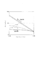
図9は実験結果を示す図である。なお、この実験は、エンジン回転数Neを1200rpm/min、平均有効圧IMEPを70kPaで行っている。また、図中、符号COVmaxは、自動二輪車用エンジンとして安定したアイドルとみなせる変動率COVの上限値である。
例えば、従来の自動二輪車用エンジンでは吸気比容積ξが30%程度に設定されており、この場合、安定したアイドルのためには当量比φが1.2以上の濃い混合気が必要となり、後処理にて排気を浄化するには二次空気の導入が必要になることが判る。
FIG. 9 is a diagram showing experimental results. In this experiment, the engine speed Ne is 1200 rpm / min, and the average effective pressure IMEP is 70 kPa. Also, in the figure, the symbol COVmax is an upper limit value of the rate of change COV that can be regarded as a stable idle for a motorcycle engine.
For example, in a conventional motorcycle engine, the intake specific volume ξ is set to about 30%. In this case, a dense air-fuel mixture with an equivalent ratio φ of 1.2 or more is required for stable idling. It can be seen that secondary air must be introduced to purify the exhaust gas in the treatment.
図9に示すように、吸気比容積ξの増加と共に変動率COVが上限値COVmaxを超える領域が希薄混合気側に推移し、吸気比容積ξが60%以上で理論空燃比(当量比φ=1)よりも希薄側になることが判った。
すなわち、本実験結果によれば、吸気比容積ξが60%未満の程度の吸気容積の増加では、二次空気導入装置を廃止できる程度にエミッション低減が低減せず、吸気比容積ξを60%以上に吸気容積を増加することで、二次空気導入装置を廃止することができるエミッション低減効果を得ることができることが判った。
As shown in FIG. 9, the region where the variation rate COV exceeds the upper limit value COVmax is shifted to the lean air-fuel mixture side as the intake specific volume ξ increases, and the theoretical air-fuel ratio (equivalent ratio φ = It turned out to be a sparser side than 1).
That is, according to the results of this experiment, an increase in intake volume such that the intake specific volume ξ is less than 60% does not reduce the emission reduction to the extent that the secondary air introduction device can be eliminated, and the intake specific volume ξ is set to 60%. It has been found that by increasing the intake volume as described above, it is possible to obtain an emission reduction effect that can eliminate the secondary air introduction device.
従って、吸気チャンバ61の容積を、スロットルバルブ51の下流側吸気通路71Bの容積との合算容積が、吸気比容積ξが60%以上となるように設定することで、混合気の当量比φが1.0以下でも燃焼が安定して燃費向上とエミッション低減とを図ることができ、二次空気導入装置を廃止できることが判った。
この場合、例えば、従来の自動二輪車用エンジンと同様に、吸気チャンバ61を含まない吸気容積(下流側吸気通路71Bに相当)の吸気比容積ξを30%程度にした場合、吸気チャンバ61を、下流側吸気通路71Bの少なくとも1倍以上の容積にすることで、全体の吸気容積を2倍以上に増加して吸気比容積ξを60%以上にすることができる。
Therefore, by setting the volume of the
In this case, for example, as in the conventional motorcycle engine, when the intake specific volume ξ of the intake volume not including the intake chamber 61 (corresponding to the
本実施形態では、少なくともエンジン10が低負荷低回転のときは混合気の当量比φが1.0以下となるようにインジェクタ33により燃料噴射量が制御される。この場合、常に当量比φが1.0以下となる燃費重視の制御をしてもよいし、混合比を可変制御して走行性能重視の制御をしてもよい。混合比を可変制御する場合は、スロットルバルブ51が所定開度以上開いた高負荷状態や高回転状態の場合に、当量比φが1.0を超える濃い混合気になるように燃料噴射量を制御することが好ましい。
In the present embodiment, the fuel injection amount is controlled by the
以上説明したように、本実施形態によれば、スロットルバルブ51が所定開度以下に閉じてエンジン10が低負荷低回転のときに、スロットルバルブ51の下流側吸気通路71Bに連通するように成した吸気チャンバ61を設けたので、低負荷低回転時の燃焼悪化(着火遅れ及び燃焼速度の低下)を改善することができる。従って、(1)遅延燃焼のため熱効率が悪い、(2)濃い混合気を与えないと安定燃焼しない、(3)排気中の未燃HC(炭化水素)が多い、といった事態を改善することができる。
しかも、本構成では、吸気チャンバ61の容積を、吸気比容積ξが60%以上となるように、つまり、少なくともスロットルバルブ51の下流側吸気通路71Bとの合算容積(吸気容積Viに相当)が行程容積Vcの60%以上となる容積に設定するので、確実に二次空気導入装置を廃止可能な程度まで希薄混合気に対する燃焼性を改善することができる。これにより、構成および制御を煩雑にすることなく、燃費向上とエミッション低減とを両立することができる。
As described above, according to the present embodiment, when the
Moreover, in this configuration, the volume of the
また、本構成では、吸気チャンバ61の容積を、スロットルバルブ51の下流側吸気通路71Bの少なくとも1倍以上の容積にすることで、従来の自動二輪車用エンジンと同様に吸気通路(下流側吸気通路71Bの容積に相当)を小さくした場合でも、吸気比容積ξを確実に60%以上にすることができる。このため、従来の自動二輪車への適用が容易である。
また、本構成では、吸気チャンバ61を、スロットルバルブ51により開閉されるパイプ部(開閉通路)31を介してスロットルバルブ51の下流側吸気通路71Bに連通させたので、スロットルバルブ51を吸気チャンバ61の開閉機構に兼用させることができる。従って、この種の開閉機構や制御機構を別途設ける場合に比して、部品点数の低減及び小型化が可能であり、これによっても構成及び制御の煩雑化を回避できる。
さらに、本構成では、スロットルバルブ51が全開の場合には、スロットルバルブ51のバルブ体51Aがパイプ部31B内に収容されるので、スロットルバルブ51の上流側吸気通路71Aと下流側吸気通路71Bとを大開口で連通させることができ、スロットル全開時の出力性能の悪化を最小限に抑えることができる。
Further, in this configuration, the volume of the
In this configuration, the
Further, in this configuration, when the
<第二実施形態>
図10及び図11は第二実施形態を示す。第二実施形態では、エンジン10が、各気筒の点火間隔が不等間隔とされた4サイクル2気筒エンジンであり、図10に示すように、このエンジン10のスロットルボディ31が、2本の吸気管30、30を介してエンジン10に接続されている。ここで、図10は、スロットルボディ31及びその周辺構成を機能的に示す図であり、図11が実際の外観図を示している。
<Second embodiment>
10 and 11 show a second embodiment. In the second embodiment, the
図10に示すように、スロットルボディ31は、吸気管30、30の各々に対応するスロットルバルブ51、51を備え、これらスロットルバルブ51、51がアクセル操作に応じて一体的に開閉する。また、このスロットルボディ31のケース31Aには、スロットルバルブ51、51により各々開閉されるパイプ部(開閉通路)31B、31Bが一体的に形成され、これらパイプ部31B、31Bが連通路形成体81を介して連通されるようになっている。この連通路形成体81は、図11に示すように、パイプ部31B、31Bを最短距離で連通させる小型カバー形状に形成され、スロットルボディ31のケース31Aに複数本のボルト82を介して簡易に固定される。
As shown in FIG. 10, the
この実施形態では、スロットルバルブ51、51を閉じた場合、図10に示すように、パイプ部31B、31Bの両方が吸気管30、30(下流側吸気通路71B、71Bに相当)に連通するので、パイプ部31B、31Bを連通する連通路形成体81によって下流側吸気通路71B、71Bを互いに連通させることができる。この場合、一方の気筒が吸気行程のときは、他方の気筒は吸気行程ではないため、上記の連通により、一方の気筒の吸気に寄与する吸気容積を、他方の気筒の下流側吸気通路71Bの容積とを合わせた二倍の容積にすることができる。
このようにして、吸気容積を容易に二倍にできるので、下流側吸気通路71B、71Bの各々の吸気容積の吸気比容積ξを、従来の自動二輪車用エンジンと同様に30%程度にしておけば、吸気比容積ξ=60%以上を容易に満足させることが可能である。
In this embodiment, when the
Since the intake volume can be easily doubled in this way, the intake specific volume ξ of each intake volume of the downstream
このように、点火間隔が不等間隔の二気筒エンジン10において、スロットルバルブ51が所定開度以下に閉じてエンジン10が低負荷低回転のときに、一方の気筒に連通する下流側吸気通路71Bと他方の気筒に連通する下流側吸気通路71Bとを連通させるので、第一実施形態の吸気チャンバ61を別途設けることなく、吸気行程に供される吸気容積を増大することができる。すなわち、吸気行程ではない気筒側の吸気通路を吸気チャンバ61に代用し、これによって容易に吸気容積を増大させることができる。
しかも、吸気容積を二倍に増大できるので、下流側吸気通路71B、71Bの各々の吸気容積の吸気比容積ξを、従来の自動二輪車用エンジンと同様に小さくした場合でも、吸気比容積ξを容易かつ確実に60%程度にすることができる。
これらにより、本実施形態では、第一実施形態で説明した各種効果に加え、他方の吸気通路を吸気チャンバ61の代用にすることで、専用の吸気チャンバを別途設ける場合に比して小型化かつ部品点数の削減が可能である。
Thus, in the two-
Moreover, since the intake volume can be doubled, even if the intake specific volume ξ of the intake volume of each of the
Thus, in this embodiment, in addition to the various effects described in the first embodiment, the other intake passage is replaced with the
以上、一実施形態に基づいて本発明を説明したが、本発明はこれに限定されるものでなく、種々の設計変形を行うことができる。例えば、上述した実施形態では、スロットルバルブ51を吸気チャンバ61(別の気筒の吸気通路を含む)に連通させる切換弁に兼用する場合を説明したが、これに限らず、スロットルバルブ51以外の切換弁を別途設けてもよい。
また、上述の第二実施形態では、独立吸気管方式の二気筒エンジンの吸気制御装置に本発明を適用する場合を説明したが、これに限らず、独立吸気管方式等の吸気容積が小さい多気筒エンジンに広く適用することができる。
さらに、本発明は、自動二輪車用エンジンの吸気制御装置に適用する場合に限らず、吸気容積が小さいエンジンの吸気制御装置に広く適用することができ、例えば、ATV(不整地走行車両)に分類される三輪車両や四輪車両等の他の車両用エンジンの吸気制御装置に適用可能である。
As mentioned above, although this invention was demonstrated based on one Embodiment, this invention is not limited to this, A various design deformation | transformation can be performed. For example, in the above-described embodiment, the case where the
In the second embodiment described above, the case where the present invention is applied to the intake control device of an independent intake pipe type two-cylinder engine has been described. However, the present invention is not limited to this, and an intake volume such as an independent intake pipe type is small. It can be widely applied to cylinder engines.
Furthermore, the present invention is not limited to being applied to an intake control device for a motorcycle engine, but can be widely applied to an intake control device for an engine having a small intake volume, for example, classified as ATV (rough terrain vehicle). The present invention is applicable to intake control devices for other vehicle engines such as three-wheel vehicles and four-wheel vehicles.
10 エンジン(内燃機関)
11 クランクケース
12 シリンダブロック
12A シリンダ室(気筒)
13 シリンダヘッド
14 ヘッドカバー
15 燃焼室
21 ピストン
23 クランクシャフト
30 吸気管
31 スロットルボディ
31A スロットルボディケース
31B パイプ部(開閉通路)
32 エアクリーナ
33 インジェクタ(燃料噴射装置)
51 スロットルバルブ(吸気絞り弁)
61 吸気チャンバ
71A 上流側吸気通路
71B、71C 下流側吸気通路
10 Engine (Internal combustion engine)
11
13
32 Air cleaner 33 Injector (fuel injection device)
51 Throttle valve (intake throttle valve)
61
Claims (4)
前記吸気絞り弁が所定開度以下のとき、前記吸気絞り弁の下流側吸気通路に内燃機関が低負荷低回転時に連通するように成した吸気チャンバを設け、前記吸気チャンバの容積は、少なくとも前記吸気絞り弁下流の吸気管容積との合算容積が行程容積の60%以上となる容積であることを特徴とする内燃機関の吸気制御装置。 In an intake control device for an internal combustion engine in which an intake throttle valve is provided in an intake passage communicating with a combustion chamber,
When the intake throttle valve has a predetermined opening or less, an intake chamber is provided in the intake passage downstream of the intake throttle valve so as to communicate with the internal combustion engine at low load and low rotation, and the volume of the intake chamber is at least An intake control device for an internal combustion engine, characterized in that a combined volume with an intake pipe volume downstream of the intake throttle valve is a volume that is 60% or more of a stroke volume.
前記吸気チャンバの容積は、前記吸気絞り弁下流の吸気管容積の少なくとも1倍以上の容積を有することを特徴とする内燃機関の吸気制御装置。 The intake control apparatus for an internal combustion engine according to claim 1,
The intake control device for an internal combustion engine, wherein the intake chamber has a volume that is at least one time larger than an intake pipe volume downstream of the intake throttle valve.
前記吸気通路と、この吸気通路が連通する気筒とは別の気筒に連通する吸気通路とを前記内燃機関の低負荷低回転時に連通させる切換弁を設け、この切換弁を介して連通させた前記別の気筒の吸気通路を前記吸気チャンバの代用としたことを特徴とする内燃機関の吸気制御装置。 The intake control device for an internal combustion engine according to claim 1 or 2,
There is provided a switching valve that communicates the intake passage and an intake passage that communicates with a cylinder other than the cylinder that communicates with the intake passage at the time of low load and low rotation of the internal combustion engine, and communicates via the switching valve. An intake control device for an internal combustion engine, characterized in that an intake passage of another cylinder is substituted for the intake chamber.
前記吸気チャンバは、前記吸気絞り弁により開閉される開閉通路を介して前記吸気絞り弁の下流側吸気通路に連通することを特徴とする内燃機関の吸気制御装置。 The intake control apparatus for an internal combustion engine according to any one of claims 1 to 3,
The intake control device for an internal combustion engine, wherein the intake chamber communicates with an intake passage downstream of the intake throttle valve through an open / close passage opened and closed by the intake throttle valve.
Priority Applications (1)
| Application Number | Priority Date | Filing Date | Title |
|---|---|---|---|
| JP2008203355A JP5049226B2 (en) | 2008-08-06 | 2008-08-06 | Intake control device for internal combustion engine |
Applications Claiming Priority (1)
| Application Number | Priority Date | Filing Date | Title |
|---|---|---|---|
| JP2008203355A JP5049226B2 (en) | 2008-08-06 | 2008-08-06 | Intake control device for internal combustion engine |
Publications (2)
| Publication Number | Publication Date |
|---|---|
| JP2010038073A true JP2010038073A (en) | 2010-02-18 |
| JP5049226B2 JP5049226B2 (en) | 2012-10-17 |
Family
ID=42010872
Family Applications (1)
| Application Number | Title | Priority Date | Filing Date |
|---|---|---|---|
| JP2008203355A Expired - Fee Related JP5049226B2 (en) | 2008-08-06 | 2008-08-06 | Intake control device for internal combustion engine |
Country Status (1)
| Country | Link |
|---|---|
| JP (1) | JP5049226B2 (en) |
Families Citing this family (1)
| Publication number | Priority date | Publication date | Assignee | Title |
|---|---|---|---|---|
| US9081307B2 (en) * | 2010-07-09 | 2015-07-14 | Asml Netherlands B.V. | Variable reluctance device, stage apparatus, lithographic apparatus and device manufacturing method |
Citations (3)
| Publication number | Priority date | Publication date | Assignee | Title |
|---|---|---|---|---|
| JPH0220726A (en) * | 1988-07-07 | 1990-01-24 | Katsunori Tanada | Operating device for hydraulic type bucket driving device |
| JP2000320415A (en) * | 1999-05-08 | 2000-11-21 | Fujio Inoue | Fuel supply device of prime mover and sectional area continuously variable mechanism in suction pipe of prime mover intake system |
| JP2006266135A (en) * | 2005-03-23 | 2006-10-05 | Mazda Motor Corp | Control device for multi-cylinder engine |
-
2008
- 2008-08-06 JP JP2008203355A patent/JP5049226B2/en not_active Expired - Fee Related
Patent Citations (3)
| Publication number | Priority date | Publication date | Assignee | Title |
|---|---|---|---|---|
| JPH0220726A (en) * | 1988-07-07 | 1990-01-24 | Katsunori Tanada | Operating device for hydraulic type bucket driving device |
| JP2000320415A (en) * | 1999-05-08 | 2000-11-21 | Fujio Inoue | Fuel supply device of prime mover and sectional area continuously variable mechanism in suction pipe of prime mover intake system |
| JP2006266135A (en) * | 2005-03-23 | 2006-10-05 | Mazda Motor Corp | Control device for multi-cylinder engine |
Also Published As
| Publication number | Publication date |
|---|---|
| JP5049226B2 (en) | 2012-10-17 |
Similar Documents
| Publication | Publication Date | Title |
|---|---|---|
| JP5310747B2 (en) | Spark ignition internal combustion engine | |
| CN104454194B (en) | The control device of compression ignition engine | |
| JP5272611B2 (en) | Spark ignition internal combustion engine | |
| JP2006283754A (en) | Engine | |
| JP2008128227A (en) | Super-high efficiency four-cycle internal combustion engine | |
| JP4980314B2 (en) | Internal combustion engine and drive system | |
| JP5049226B2 (en) | Intake control device for internal combustion engine | |
| WO2016051623A1 (en) | Diesel engine | |
| JP5896288B2 (en) | Control device for internal combustion engine | |
| JP2010031685A (en) | Spark ignition internal combustion engine | |
| JP6252006B2 (en) | Engine control device | |
| JP2011144694A (en) | Intake device for internal combustion engine | |
| JP2019138266A (en) | Control device of internal combustion engine | |
| Kawawa et al. | Development of New 3.5 L V6 Gasoline Direct Injection Engine | |
| JP4297044B2 (en) | Internal combustion engine | |
| JP2014074334A (en) | Internal combustion engine | |
| JP2012112263A (en) | Control device of internal combustion engine | |
| JP2008202406A (en) | Intake valve controller of internal combustion engine and internal combustion engine having same | |
| JP2006161691A (en) | Internal combustion engine | |
| JP2010024971A (en) | Internal combustion engine | |
| JP2007321767A (en) | Variable valve type internal combustion engine and control method | |
| JP2009052505A (en) | Internal combustion engine | |
| JP2006161581A (en) | Internal combustion engine | |
| JP5206274B2 (en) | Design method of spark ignition internal combustion engine | |
| JP2021055580A (en) | Engine device |
Legal Events
| Date | Code | Title | Description |
|---|---|---|---|
| A621 | Written request for application examination |
Free format text: JAPANESE INTERMEDIATE CODE: A621 Effective date: 20101126 |
|
| A131 | Notification of reasons for refusal |
Free format text: JAPANESE INTERMEDIATE CODE: A131 Effective date: 20111227 |
|
| A977 | Report on retrieval |
Free format text: JAPANESE INTERMEDIATE CODE: A971007 Effective date: 20111227 |
|
| A521 | Written amendment |
Free format text: JAPANESE INTERMEDIATE CODE: A523 Effective date: 20120224 |
|
| RD02 | Notification of acceptance of power of attorney |
Free format text: JAPANESE INTERMEDIATE CODE: A7422 Effective date: 20120224 |
|
| TRDD | Decision of grant or rejection written | ||
| A01 | Written decision to grant a patent or to grant a registration (utility model) |
Free format text: JAPANESE INTERMEDIATE CODE: A01 Effective date: 20120626 |
|
| A01 | Written decision to grant a patent or to grant a registration (utility model) |
Free format text: JAPANESE INTERMEDIATE CODE: A01 |
|
| A61 | First payment of annual fees (during grant procedure) |
Free format text: JAPANESE INTERMEDIATE CODE: A61 Effective date: 20120720 |
|
| FPAY | Renewal fee payment (event date is renewal date of database) |
Free format text: PAYMENT UNTIL: 20150727 Year of fee payment: 3 |
|
| R150 | Certificate of patent or registration of utility model |
Free format text: JAPANESE INTERMEDIATE CODE: R150 |
|
| LAPS | Cancellation because of no payment of annual fees |