JP2010037811A - Device for temporarily placing building materials on temporary scaffold - Google Patents
Device for temporarily placing building materials on temporary scaffold Download PDFInfo
- Publication number
- JP2010037811A JP2010037811A JP2008201918A JP2008201918A JP2010037811A JP 2010037811 A JP2010037811 A JP 2010037811A JP 2008201918 A JP2008201918 A JP 2008201918A JP 2008201918 A JP2008201918 A JP 2008201918A JP 2010037811 A JP2010037811 A JP 2010037811A
- Authority
- JP
- Japan
- Prior art keywords
- main body
- apparatus main
- fitting
- flange member
- single pipe
- Prior art date
- Legal status (The legal status is an assumption and is not a legal conclusion. Google has not performed a legal analysis and makes no representation as to the accuracy of the status listed.)
- Granted
Links
Images


Landscapes
- Conveying And Assembling Of Building Elements In Situ (AREA)
Abstract
Description
本発明は、建築現場に枠組み仮設される仮設足場において、仮設足場の枠組みの際に、仮設足場を構成する安全手摺等の建築資材を、枠組み作業を能率的に行うために枠組み作業途上の仮設足場に仮置きするための仮置き装置に関する。 The present invention relates to a temporary scaffold that is temporarily installed in a construction site, and in the framework of the temporary scaffold, the construction materials such as safety handrails that constitute the temporary scaffold are temporarily installed during the framework work in order to efficiently perform the framework work. The present invention relates to a temporary placement device for temporary placement on a scaffold.
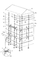
図8に示すように、建築現場では、新築や改装作業のために、建物Hの周囲に仮設足場Aが枠組み仮設される。この仮設足場Aは、単管よりなる支柱本体1aに複数の板状のフランジ部材2が所要間隔に溶接固着された支柱1が、建物Hの周囲に沿うように直立配設されるとともに、各支柱1,1間に安全手摺用や支柱1,1間を連結する支柱間連結用の単管3aがフランジ部材2に楔止めされ、また各支柱1,1間に足場台4を取り付けるための足場台支持用ブラケット3bがフランジ部材2に楔止めされ、このようにしてこれら単管3aや足場台取付用ブラケット3b等の建築資材3が地上の最下層から順次高所に向かって多段状に枠組みされる。
As shown in FIG. 8, a temporary scaffold A is temporarily installed around a building H at a construction site for new construction or renovation work. In this temporary scaffold A, a
この際に、建築資材3を用いて順次最下層から高所に向かって枠組みされるにつれて、建築資材3を地上から高所にいちいち運搬するのでは不能率であるから、高所作業になるにつれて、図示のように所定高さ位置に枠組みされている足場台4に、多数の単管3aや支持ブラケット3b等の建築資材3を一旦仮置きしておき、その位置から建築資材3を用いてその後の枠組み作業を行うようにすれば、いちいち地上から建築資材3を運搬するのに比べて枠組み作業を格段に能率的に行うことができる。
At this time, it is impossible to transport the
しかし、これら建築資材3を足場台4に仮置きするのに、図示のように足場台4上に建築資材3を載置しておくだけであるから、作業者が建築資材3に足を取られたり、建築資材3が不測に足場台4上から落下する危険性が多分にあった。
However, in order to temporarily place the
上記のように、建築資材を所要高さ位置に仮置きするのに、足場台上に単に載置するだけであるから、仮置き状態が極めて不安定であり、また枠組み作業の支障にもなる。 As mentioned above, the building material is temporarily placed on the scaffolding to temporarily place the building material at the required height position, so the temporary placing state is extremely unstable and also hinders the framework work. .
そこで本発明は、建築資材を所要高さ位置に仮置きする際に、所要高さ位置から建築資材が不測に落下しないよう安全に仮置きすることができるとともに、枠組み作業に支障を来さないような位置に仮置きすることができる仮置き装置を提案することを解決課題とする。 Therefore, when temporarily placing the building material at the required height position, the present invention can safely place the building material so that it does not accidentally drop from the required height position, and does not hinder the frame work. It is an object of the present invention to propose a temporary placement device that can be temporarily placed at such a position.
上記課題を解決するための手段を、後述する実施形態の参照符号を付して説明すると、請求項1に係る発明は、支柱本体1aに所要間隔でフランジ部材2が固着されてなる支柱1,1間に、前記フランジ部材2に楔止めされて安全手摺用或いは支柱間連結用の単管3aが順次高所に向かって多段状に枠組みされる仮設足場Aにおいて、単管3aが高所に向かって多段状に枠組みされる際に、枠組み作業を能率的に行うためにその枠組み作業途上で単管3aや足場板支持用ブラケット3b等の建築資材3を、仮設足場Aの所要高さ位置に仮置きするための仮置き装置であって、支柱1のフランジ部材2に楔止めされる上記単管3aに沿って、そのフランジ部材2の楔孔2aを利用してこれに差し込み係合する差し込み金具5を一端部に設け、他端部に単管3aにフック状に係合する係合金具6を設けた装置本体7が配置され、該装置本体7にその長手方向に隣接して並立状態に建築資材3を仮置き保持するための保持部8が設けられてなる構成を採用してなるものである。
Means for solving the above problems will be described with reference numerals of the embodiments described later. The invention according to
また請求項2に係る発明は、前記装置本体7は、水平片部7aと垂直片部7bとで構成された断面L字状の帯板状部材7Aからなり、前記差し込み金具5は、前記装置本体7の水平片部7aに垂直に固着される垂直取付部5aと該垂直取付部5aに対してL字状に延びる水平差し込み部5bとからなり、前記係合金具6は単管3aの外周面に沿って係合するフック金具6aからなり、前記保持部8は、前記装置本体7の垂直片部7bから上方に向かって突出状に固着され、建築資材3の端部開口孔9に係嵌可能な突状片8aからなる請求項1に記載の構成からなるものである。
According to a second aspect of the present invention, the apparatus
また請求項3に係る発明は、前記装置本体7の一端部に設けられる差し込み金具5の近傍に、その上端部が装置本体7に固着される垂直取付部10aとこれよりL字状に延びてし支柱本体1aに当接する水平当接部10bとからなる回転防止金具10が設けられてなる請求項1または2に記載の構成からなるものである。
Further, in the invention according to
さらに請求項4に係る発明は、前記フック金具6aに自重ロック形のロック片6bが取り付けられてなる請求項2に記載の構成からなるものである。
Further, the invention according to
さらにまた請求項5に係る発明は、前記装置本体7を前記単管3aに沿うように取り付けるに当たって、該装置本体7を水平な単管3aに対して上方に直立状に対向させて該装置本体7の一端部の差し込み金具5の水平差し込み部5bをフランジ部材2に対して垂直状となし、この状態で該水平差し込み部5bをフランジ部材2の楔孔2aに上方から嵌合し、しかる後に該装置本体7を前記単管3aに沿うよう水平状態に回動させることによって前記差し込み金具5の垂直取付部5aがフランジ部材2の楔孔2aに嵌合位置し、前記水平差し込み部5bがフランジ部材2の裏面側に沿うように配置され、これによって装置本体7の一端部がフランジ部材2に接した状態で差し込み金具5がフランジ部材2に係合し、且つ装置本体7が単管3aに沿うように配置され、しかも装置本体7の他端部の係合金具6が単管3aに係合するようになっている請求項1〜4の何れかに記載の構成からなるものである。
Furthermore, in the invention according to
上記解決手段による発明の効果を、後述する実施形態の参照符号を付して説明すると、請求項1に係る発明によれば、支柱1のフランジ部材2に楔止めされる単管3aに沿って、そのフランジ部材2の楔孔2aを利用してこれに差し込み係合する差し込み金具5を一端部に設け、他端部に単管3aにフック状に係合する係合金具6を設けた装置本体7が配置され、該装置本体7にその長手方向に隣接して並立状態に建築資材3を仮置き保持するための保持部8が設けられてなるため、該保持部8に建築資材3の端部開口孔9を係嵌することによって、建築資材3は、支柱1,1間の単管3aに沿って仮設足場Aの所要高さ位置に確実に仮置き保持させることができ、作業者が作業中に建築資材3に触れても、建築資材3は保持部8から脱落することがなく安全に仮置きすることができ、しかも足場台4上に仮置きすることがないから、足場台4上での作業に支障を来すことがない。さらには建築資材3は直立状態に装置本体7に保持されるから、建築資材3が長尺のものであっても、これに制約されることなく仮置き保持させることができる。
The effect of the invention by the above solution will be described with reference numerals of the embodiments described later. According to the invention according to
また請求項2に係る発明は、前記装置本体7は、水平片部7aと垂直片部7bとで構成された断面L字状の帯板状部材7Aからなり、前記差し込み金具5は、前記装置本体7の水平片部7aに垂直に固着される垂直取付部5aと該垂直取付部5aに対してL字状に延びる水平差し込み部5bとからなり、前記係合金具6は単管3aの外周面に沿って係合するフック金具6aからなり、前記保持部8は、前記装置本体7の垂直片部7bから上方に向かって突出状に固着され、建築資材3の端部開口孔9に係嵌可能な突状片8aからなるため、構成が簡単で安価に製作することができる。
According to a second aspect of the present invention, the apparatus
また請求項3に係る発明は、前記装置本体7の一端部に設けられる差し込み金具5の近傍に、その上端部が装置本体7に固着される垂直取付部10aとこれよりL字状に延びて支柱本体1aの側面に当接する水平当接部10bとからなる回転防止金具10が設けられてなるため、装置本体7に多数の建築資材3が取り付けられ、これらの大きな荷重が装置本体7に負荷しても、前記差し込み金具5と係合金具6と回転防止金具10とによって、確実に装置本体7は前記フランジ部材2および単管3aに取り付けられ、装置本体7がこれらの取付部から脱落することがない。
Further, in the invention according to
さらに請求項4に係る発明は、前記フック金具6aに自重ロック形のロック片6bが取り付けられてなるため、装置本体7は一層確実に単管3aに係合保持させることができる。
Further, in the invention according to
さらにまた請求項5に係る発明は、前記装置本体7を前記単管3aに沿うように取り付けるに当たって、該装置本体7を水平な単管3aに対して上方に直立状に対向させて該装置本体7の一端部の差し込み金具5の水平差し込み部5bをフランジ部材2に対して垂直状となし、この状態で該水平差し込み部5bをフランジ部材2の楔孔2aに上方から嵌合し、しかる後に該装置本体7を前記単管3aに沿うよう水平状態に回動させることによって前記差し込み金具5の垂直取付部5aがフランジ部材2の楔孔2aに嵌合位置し、前記水平差し込み部5bがフランジ部材2の裏面側に沿うように配置され、これによって装置本体7の一端部がフランジ部材2に接した状態で差し込み金具5がフランジ部材2に係合し、且つ装置本体7が単管3aに沿うように配置され、しかも装置本体7の他端部の係合金具6が単管3aに係合するようになっているため、装置本体7は、差し込み金具5と係合金具6との簡単な係合手段にも係わらず、確実に装置本体7をフランジ部材2と単管3aに取り付けることができる。また装置本体7をボルト止めなどの面倒な固着作業を必要とせず上記簡単な係合手段によって取り付けることができるため、その取付作業を容易迅速に行うことができる。さらにまた装置本体7をフランジ部材2と単管3aとから離脱させる際には上記取付作業と反対の順序で行えばよいから離脱作業も容易迅速に行うことができる。このことは、例えば、建築資材3を用いて高所に向かって多段状に枠組みされるにしたがって、装置本体7の取付位置をたびたび高所に取り替えなければならないが、本発明では上述のように装置本体7のフランジ部材2や単管3aに対する取付や取り外し作業を容易迅速に行うことができるため、結果的に、仮設足場の仮設作業中での建築資材3の仮置き作業を能率的に行うことができることになる。
Furthermore, in the invention according to
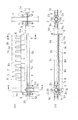
以下に本発明の好適な一実施形態を図面に基づいて説明すると、図1は、所謂一側足場と称される仮設足場Aを示し、従来と同じように、鋼製単管よりなる支柱本体1aに複数の板状のフランジ部材2が所要間隔に溶接固着されてなる支柱1が、建物Hの周囲に沿うように直立配設されるとともに、各支柱1,1間に、安全手摺用や支柱1,1間を連結する支柱間連結用の単管3aがフランジ部材2に楔止めされ、また各支柱1,1間に足場台4を取り付けるための足場台支持用ブラケット3bがフランジ部材2に楔止めされ、このようにしてこれら単管3aや足場台取付用ブラケット3b等の建築資材3が地上の最下層から順次高層階に向かって多段状に枠組みされる。
A preferred embodiment of the present invention will be described below with reference to the drawings. FIG. 1 shows a temporary scaffold A called a so-called one-side scaffold, and a column main body made of a single steel pipe as in the prior art. A
そして、本発明の特徴とする点であるが、図示のように、支柱間連結用の単管3aや足場台取付用ブラケット3b等の建築資材3が独特構造の装置本体7によって単管3aに沿って仮置き保持されるようになっていることである。これによる利点は、上述の作用効果の項で説明したとおりである。
And, as a characteristic feature of the present invention, as shown in the drawing, the
本発明の特徴とする装置本体7の最良の実施形態は、図2〜図7に示すとおりであるであるが、まず図2によく表れているので、その構造を説明すると、装置本体7は、水平片部7aと垂直片部7bとで構成された断面L字状の帯板状部材7Aからなり、該帯板状部材7Aの一端部には、支柱1のフランジ部材2の楔孔2aを利用してこれに差し込み係合する差し込み金具5が設けられ、他端部に単管3aにフック状に係合する係合金具6が設けられ、該帯板状部材7Aにその長手方向に隣接して保持部8が設けられる。該保持部8は、前記帯板状部材7Aの垂直片部7bから上方に向かって突出状に固着され、後述のように建築資材3の端部開口孔9(図7)に係嵌可能な板状の突状片8aからなる。
The best embodiment of the apparatus
前記差し込み金具5は、前記装置本体7である帯板状部材7Aの水平片部7aを貫通して溶接によって該水平片部7aに垂直に固着される垂直取付部5aと該垂直取付部5aに対してL字状に延びる水平差し込み部5bとからなる。
The
前記係合金具6は単管3aの外周面に沿って係合するフック金具6aからなり、該フック金具6aは、図示のようにその先端部に自重ロック形のロック片6bが取り付けられて、フック金具6aを単管3aに係合させることによって、ロック片6bが自重で単管3aの回りに潜り込みロック作用を良好にする作用を有する(図6)。勿論、ロック片6bを設けないで、フック金具6aだけでもよく、この場合にフック金具6aのU字状係合部の係合深さをできるだけ深くすることが係合作用を良好にすることになる。
The engaging
また帯板状部材7Aの一端部に設けられる差し込み金具5の近傍に、その上端部が帯板状部材7Aの水平片部7aに固着される垂直取付部10aとこれよりL字状に延びて、後述のように(図5)、支柱本体1aの側面に当接する水平当接部10bとからなるL字状に折曲した板状の回転防止金具10が設けられる。
Further, in the vicinity of the insertion fitting 5 provided at one end portion of the
前述のように、支柱本体1aにはその長手方向適当間隔にフランジ部材2が固着されているが、このフランジ部材2には、周方向等間隔の4箇所に楔孔2aが貫通して設けられる。単管3aの両端部は開口9しており、図2の矢印の方向に拡大して図示するように、該単管3aをフランジ部材2に楔止めするための連結部11が設けられ、この連結部11は、端部開口孔9を含んで二股状になってフランジ部材2に対して連結部11を差し込みことができる差込み孔12が形成されている。そして図示のように連結部11の差込み孔12をフランジ部材2に差し込み、差込み孔12を挟んで連結部11に上下に形成された係合孔13とフランジ部材2の楔孔2aとにわたって楔14を打ち込むことによって、単管3aをフランジ部材2に楔止めするようになっている。
As described above, the
装置本体7である帯板状部材7Aは、フランジ部材2の楔孔2aを利用して、単管3aに沿って取り付けられるようになっている。
The band plate-
図3〜図4は、帯板状部材7Aの取付順序を示すもので、支柱1には、横部材である単管3a,3aがその連結部11とフランジ部材2にわたって楔14を打ち込んで楔止めしている状態が示されている。このように枠組みされた仮設足場の枠組み途上で、まず、図3の(a)に示すように、帯板状部材7Aを水平な単管3aに対して上方に直立状に対向させて該帯板状部材7Aの一端部の差し込み金具5の水平差し込み部5bをフランジ部材2に対して垂直状となし、この状態で矢印で示すように、該水平差し込み部5bをフランジ部材2の楔孔2aに上方から嵌合し、しかる後に(b)に示すように、帯板状部材7Aを矢印で示すように、単管3aに沿うよう水平状態に回動させることによって、図4の(a)に示すように、前記差し込み金具5の垂直取付部5aがフランジ部材2の楔孔2aに嵌合位置し、前記水平差し込み部5bがフランジ部材2の裏面側に沿うように配置され、これによって装置本体7である帯板状部材7Aの一端部がフランジ部材2に接した状態で差し込み金具5がフランジ部材2に係合し、且つ帯板状部材7Aが単管3aに沿うように配置され、しかも帯板状部材7Aの他端部の係合金具6が図6に示すように単管3aに係合するようになっており、係合金具6であるフック金具6aの先端部に取り付けたロック片6bが単管3aの下面側に自重で回ることでロック作用を良好にするようになっている。
3 to 4 show the mounting order of the band plate-
さらには、図5に示すように、帯板状部材7Aの一端部に設けられた回転防止金具10の水平当接部10bが支柱本体1aの側面に当接して、装置本体7である帯板状部材7Aが単管3aから離反する方向にあるいは単管3a側に倒れるのを防止するようになっている。
Furthermore, as shown in FIG. 5, the
図7は、建築資材3を装置本体7である帯板状部材7Aに仮置き係合した状態を示すもので、図1に示す建築資材3の仮置き状態を側面から拡大した状態を示す。一般に仮設足場で枠組みされる手摺用あるいは支柱間連結用鋼製単管3aや足場板支持用ブラケット3b等の建築資材3の端部は前述のように開口しており、この端部開口孔9を挟んで、フランジ部材2に差し込んで楔止めされるための二股状の連結部11が設けられている。
本発明は、この端部開口孔9や二股状連結部11の差し込み孔12を利用して、図7の矢印の方向に拡大して示すように、建築資材3の下端部を端部開口孔9や差し込み孔12を帯板状部材7Aに突設した板状保持部8,8aに嵌合し、拡大図に示すように、該保持部8,8aの上端縁が差し込み孔12の内周縁に当接するようにして係合させ、建築資材3の上端部付近を、例えば上方側に枠組みされている足場台4の側面側に立て掛けさせることによって、建築資材3を直立状態に単管3aに沿って仮置き保持させるようになっている。
FIG. 7 shows a state in which the
The present invention utilizes the
このようにして、建築資材3を装置本体7に仮置き保持させることによって、例え建築資材3が図7の仮想線で示すように、足場台4から離反する方向に倒れかかっても、建築資材3の下端部が装置本体7の保持部8に係合されて、装置本体7から脱落することがなく安全に仮置き保持させることができる。
In this way, even if the
このように、装置本体7である帯板状部材7Aが差し込み金具5と係合金具6との簡単な係合手段にも係わらず、確実に装置本体7をフランジ部材2と単管3aに取り付けることができる。また装置本体7をボルト止めなどの面倒な固着作業を必要とせず上記簡単な係合手段によって取り付けることができるため、その取付作業を容易迅速に行うことができる。さらにまた帯板状部材7Aをフランジ部材2と単管3aとから離脱させる際には上記取付作業と反対の順序で行えばよいから離脱作業も容易迅速に行うことができる。このことは、例えば、建築資材3を用いて高所に向かって多段状に枠組みされるにしたがって、帯板状部材7Aの取付位置をたびたび高所に移し替えなければならないが、本発明では上述のように帯板状部材7Aのフランジ部材2や単管3aに対する取付や取り外し作業を容易迅速に行うことができるため、結果的に、仮設足場の仮設作業中での建築資材3の仮置き作業を能率的に行うことができることになる。
In this way, the apparatus
H 建物
A 仮設足場
1 支柱
1a 支柱本体
2 フランジ部材
2a 楔孔
3 建築資材
3a 単管
3b 足場板支持用ブラケット
4 足場台
5 差し込み金具
5a 垂直取付部
5b 水平差し込み部
6 係合金具
6a フック金具
6b ロック片
7 装置本体
7A 帯板状部材
7a 水平片部
7b 垂直片部
8 保持部
8a 突状片
9 端部開口孔
10 回転防止金具
10a 垂直取付部
10b 水平当接部
11 連結部
12 差し込み孔
13 係合孔
14 楔
H Building
Claims (5)
Priority Applications (1)
| Application Number | Priority Date | Filing Date | Title |
|---|---|---|---|
| JP2008201918A JP5070156B2 (en) | 2008-08-05 | 2008-08-05 | Temporary placement equipment for temporary scaffolding of building materials |
Applications Claiming Priority (1)
| Application Number | Priority Date | Filing Date | Title |
|---|---|---|---|
| JP2008201918A JP5070156B2 (en) | 2008-08-05 | 2008-08-05 | Temporary placement equipment for temporary scaffolding of building materials |
Publications (2)
| Publication Number | Publication Date |
|---|---|
| JP2010037811A true JP2010037811A (en) | 2010-02-18 |
| JP5070156B2 JP5070156B2 (en) | 2012-11-07 |
Family
ID=42010643
Family Applications (1)
| Application Number | Title | Priority Date | Filing Date |
|---|---|---|---|
| JP2008201918A Expired - Fee Related JP5070156B2 (en) | 2008-08-05 | 2008-08-05 | Temporary placement equipment for temporary scaffolding of building materials |
Country Status (1)
| Country | Link |
|---|---|
| JP (1) | JP5070156B2 (en) |
Cited By (1)
| Publication number | Priority date | Publication date | Assignee | Title |
|---|---|---|---|---|
| KR102516500B1 (en) * | 2022-05-24 | 2023-03-31 | 이미경 | Safety cover for scaffolding |
Families Citing this family (1)
| Publication number | Priority date | Publication date | Assignee | Title |
|---|---|---|---|---|
| CN101278403B (en) * | 2005-10-14 | 2010-12-01 | 株式会社半导体能源研究所 | Semiconductor device and manufacture method thereof |
Citations (5)
| Publication number | Priority date | Publication date | Assignee | Title |
|---|---|---|---|---|
| JPH0343918U (en) * | 1989-09-06 | 1991-04-24 | ||
| JP2002013291A (en) * | 2000-06-29 | 2002-01-18 | Fumio Fujiki | Scaffolding fabric board |
| JP2003120017A (en) * | 2001-10-10 | 2003-04-23 | Fumio Fujiki | Scaffolding device |
| JP2006316567A (en) * | 2005-05-16 | 2006-11-24 | Tomika Kon | External facing material holder for scaffold work |
| JP2008088804A (en) * | 2007-11-19 | 2008-04-17 | Kawanogumi:Kk | Ledger plate displacement prevention fixture |
-
2008
- 2008-08-05 JP JP2008201918A patent/JP5070156B2/en not_active Expired - Fee Related
Patent Citations (5)
| Publication number | Priority date | Publication date | Assignee | Title |
|---|---|---|---|---|
| JPH0343918U (en) * | 1989-09-06 | 1991-04-24 | ||
| JP2002013291A (en) * | 2000-06-29 | 2002-01-18 | Fumio Fujiki | Scaffolding fabric board |
| JP2003120017A (en) * | 2001-10-10 | 2003-04-23 | Fumio Fujiki | Scaffolding device |
| JP2006316567A (en) * | 2005-05-16 | 2006-11-24 | Tomika Kon | External facing material holder for scaffold work |
| JP2008088804A (en) * | 2007-11-19 | 2008-04-17 | Kawanogumi:Kk | Ledger plate displacement prevention fixture |
Cited By (1)
| Publication number | Priority date | Publication date | Assignee | Title |
|---|---|---|---|---|
| KR102516500B1 (en) * | 2022-05-24 | 2023-03-31 | 이미경 | Safety cover for scaffolding |
Also Published As
| Publication number | Publication date |
|---|---|
| JP5070156B2 (en) | 2012-11-07 |
Similar Documents
| Publication | Publication Date | Title |
|---|---|---|
| JP5384092B2 (en) | Temporary structure erection member | |
| JP5070156B2 (en) | Temporary placement equipment for temporary scaffolding of building materials | |
| JP3851105B2 (en) | Construction method of temporary structure and handrail braiding used for this | |
| JP2014101659A (en) | Temporary scaffold and method of assembling the same | |
| JP2012197609A (en) | Precedence balustrade | |
| JP2009155875A (en) | Temporary scaffolding connection structure | |
| JP6832554B1 (en) | Leading handrail | |
| JP2006233504A (en) | Handrail member, temporary member and assembly method of the temporary member | |
| KR20210013450A (en) | Scaffolding piece | |
| JP2019031837A (en) | Stair handrail for temporary scaffolding | |
| JPH11229629A (en) | Safety rope support device for construction | |
| JP2020076252A (en) | Metal fitting for construction | |
| JP2010077648A (en) | Device for temporarily placing material for temporary construction on temporary scaffold | |
| JP2008031667A (en) | Funnel-shaped protective shelf device | |
| JP3197050U (en) | Scaffolding | |
| JP2013036257A (en) | Temporary handrail | |
| JP4667398B2 (en) | Scaffolding strut and horizontal stay connection device | |
| JP5409955B1 (en) | Steel bridge structure | |
| JP3151909U (en) | Temporary scaffolding baseboard clip | |
| KR20130000022A (en) | Ladder holder and grating structure having the same | |
| JP2010248881A (en) | Temporary scaffolding and temporary scaffolding member fitting | |
| JP2009127338A (en) | Wall surface panel ground assembly device and ground assembly method of wall surface panel | |
| JP2017025537A (en) | Member for temporary scaffold | |
| JP5111267B2 (en) | Coil mounting bracket | |
| JPH09268755A (en) | Stile for protection of temporary scaffolding |
Legal Events
| Date | Code | Title | Description |
|---|---|---|---|
| A621 | Written request for application examination |
Free format text: JAPANESE INTERMEDIATE CODE: A621 Effective date: 20100308 |
|
| A977 | Report on retrieval |
Free format text: JAPANESE INTERMEDIATE CODE: A971007 Effective date: 20111212 |
|
| A131 | Notification of reasons for refusal |
Free format text: JAPANESE INTERMEDIATE CODE: A131 Effective date: 20111216 |
|
| A521 | Request for written amendment filed |
Free format text: JAPANESE INTERMEDIATE CODE: A523 Effective date: 20120117 |
|
| TRDD | Decision of grant or rejection written | ||
| A01 | Written decision to grant a patent or to grant a registration (utility model) |
Free format text: JAPANESE INTERMEDIATE CODE: A01 Effective date: 20120801 |
|
| A01 | Written decision to grant a patent or to grant a registration (utility model) |
Free format text: JAPANESE INTERMEDIATE CODE: A01 |
|
| A61 | First payment of annual fees (during grant procedure) |
Free format text: JAPANESE INTERMEDIATE CODE: A61 Effective date: 20120820 |
|
| FPAY | Renewal fee payment (event date is renewal date of database) |
Free format text: PAYMENT UNTIL: 20150824 Year of fee payment: 3 |
|
| R150 | Certificate of patent or registration of utility model |
Free format text: JAPANESE INTERMEDIATE CODE: R150 Ref document number: 5070156 Country of ref document: JP Free format text: JAPANESE INTERMEDIATE CODE: R150 |
|
| R250 | Receipt of annual fees |
Free format text: JAPANESE INTERMEDIATE CODE: R250 |
|
| R250 | Receipt of annual fees |
Free format text: JAPANESE INTERMEDIATE CODE: R250 |
|
| R250 | Receipt of annual fees |
Free format text: JAPANESE INTERMEDIATE CODE: R250 |
|
| R250 | Receipt of annual fees |
Free format text: JAPANESE INTERMEDIATE CODE: R250 |
|
| R250 | Receipt of annual fees |
Free format text: JAPANESE INTERMEDIATE CODE: R250 |
|
| R250 | Receipt of annual fees |
Free format text: JAPANESE INTERMEDIATE CODE: R250 |
|
| LAPS | Cancellation because of no payment of annual fees |