JP2010037605A - Barrel plating device - Google Patents
Barrel plating device Download PDFInfo
- Publication number
- JP2010037605A JP2010037605A JP2008202685A JP2008202685A JP2010037605A JP 2010037605 A JP2010037605 A JP 2010037605A JP 2008202685 A JP2008202685 A JP 2008202685A JP 2008202685 A JP2008202685 A JP 2008202685A JP 2010037605 A JP2010037605 A JP 2010037605A
- Authority
- JP
- Japan
- Prior art keywords
- barrel
- barrel container
- container
- plating apparatus
- arm
- Prior art date
- Legal status (The legal status is an assumption and is not a legal conclusion. Google has not performed a legal analysis and makes no representation as to the accuracy of the status listed.)
- Granted
Links
Images


Abstract
Description
この発明は、ばら状の被めっき物を電解めっきするバレルめっき装置に関する。 The present invention relates to a barrel plating apparatus for electrolytically plating a rose-shaped object to be plated.
バレル容器を電解めっき浴中で回転させて、投入されたばら状の被めっき物を電解めっきするバレルめっき装置は、筒状のバレル容器をめっき浴中で水平向きとして、モータ等の駆動装置によって、軸心の回りに一方向に回転駆動するものが多く、このバレル容器の回転駆動によって、バレル容器の下部側の側壁に沿って移動するばら状の被めっき物を相互に流動させ、容器内に配置した陰極と接触させて均一に電解めっきを施す。 A barrel plating apparatus that rotates a barrel container in an electroplating bath and electroplates a charged object to be plated is placed in a horizontal direction in the plating bath by a driving device such as a motor. Many of them are driven to rotate around the axis in one direction, and this barrel container is driven to rotate, causing the rose-shaped objects to move along the side wall on the lower side of the barrel container to flow to each other. Electrolytic plating is uniformly applied by contacting with the cathode disposed in the plate.
しかしながら、被めっき物が金属粉末やカーボン粉末等の細かい粉末状のものである場合は、バレル容器を一方向に回転駆動しても、投入された粉末状の被めっき物の層が、内部で凝集したまま下部側の側壁に沿って移動するので、層内での相互流動が悪くなって、均一な電解めっきを施こすことができない問題がある。 However, when the object to be plated is a fine powder such as metal powder or carbon powder, the layer of the powdered object to be plated is not contained inside even if the barrel container is rotated in one direction. Since it moves along the side wall on the lower side while being agglomerated, there is a problem that the mutual flow within the layer is deteriorated and uniform electrolytic plating cannot be performed.
このような粉末状の被めっき物の凝集を防止する手段としては、めっき槽内に流体振動撹拌手段を設ける方法(例えば、特許文献1参照)や、バレル容器に振動を付与する方法(例えば、特許文献2参照)が提案されている。 As a means for preventing such agglomeration of the powder-like object to be plated, a method of providing a fluid vibration stirring means in the plating tank (for example, see Patent Document 1) or a method of applying vibration to the barrel container (for example, Patent Document 2) has been proposed.
特許文献1に記載されためっき槽内に流体振動撹拌手段を設ける方法は、装置が複雑で高価なものとなるとともに、めっき槽内のめっき液に波が生じ、めっき液が飛散する恐れもある。また、特許文献2に記載されたバレル容器に振動を付与する方法は、回転駆動されるバレル容器の支持機構が複雑になるとともに、バレル容器の回転駆動系が故障しやすくなり、装置のメンテナンスが難しい問題がある。
The method of providing the fluid vibration agitation means in the plating tank described in Patent Document 1 makes the apparatus complicated and expensive, and there is also a possibility that the plating solution in the plating vessel may generate waves and the plating solution may scatter. . In addition, the method of applying vibration to the barrel container described in
そこで、本発明の課題は、簡単でメンテナンスが容易な構成で、粉末状の被めっき物であっても、バレル容器の下部側の側壁に沿って移動する際に、層内で十分な相互流動が生じるようにすることである。 Therefore, an object of the present invention is to provide a sufficient mutual flow within the layer when moving along the side wall on the lower side of the barrel container even if the object is a powdery object with a simple and easy-to-maintain configuration. Is to occur.
上記の課題を解決するために、本発明は、電解めっき浴中で水平向きとした筒状のバレル容器を水平な軸心の回りに回転させて、前記バレル容器に投入されたばら状の被めっき物を電解めっきするバレルめっき装置において、前記バレル容器を軸心と直交方向に往復運動させ、この往復運動の往方向と復方向とで、前記バレル容器の回転方向を反転させる構成を採用した。 In order to solve the above-mentioned problems, the present invention is to rotate a cylindrical barrel container that is horizontally oriented in an electrolytic plating bath around a horizontal axis, and to form a rose-shaped covering placed in the barrel container. In a barrel plating apparatus for electrolytically plating a plated product, the barrel container is reciprocated in a direction orthogonal to the axis, and the rotation direction of the barrel container is reversed between the forward and backward directions of the reciprocation. .
すなわち、バレル容器を軸心と直交方向に往復運動させ、この往復運動の往方向と復方向とで、バレル容器の回転方向を反転させることにより、粉末状の被めっき物であっても、バレル容器の下部側の側壁に沿って移動する際に、層内で十分な相互流動が生じるようにした。 That is, the barrel container is reciprocated in a direction orthogonal to the axis, and the barrel container is rotated in the forward direction and the backward direction of the reciprocating movement, thereby rotating the barrel container in the barrel direction. When moving along the lower side wall of the container, sufficient mutual flow was created within the bed.
前記バレル容器を往方向と復方向とで回転方向を反転させる手段を、前記バレル容器の両端部に、バレル容器と一体で軸心の回りに回転する車輪を設け、前記めっき浴中に、前記バレル容器の両端部の車輪が転動する一対の平行なレールを設けて、前記バレル容器を前記車輪で前記レールに沿って往復転動させるものとすることにより、簡単でメンテナンスが容易な構成で、バレル容器を往方向と復方向とで回転方向を反転させることができる。 The means for reversing the rotation direction of the barrel container in the forward direction and the backward direction is provided at both ends of the barrel container with wheels rotating around the axis integrally with the barrel container, and in the plating bath, By providing a pair of parallel rails on which the wheels on both ends of the barrel container roll, the barrel container is reciprocatingly rolled along the rail with the wheels, so that the configuration is simple and easy to maintain. The rotation direction of the barrel container can be reversed between the forward direction and the backward direction.
前記車輪を外周に歯車を形成した歯車輪とし、前記レールを上面に前記歯車が噛み合うラックを形成したラックレールとすることにより、車輪とレール間のスリップを防止することができる。 By making the wheel a toothed wheel having a gear formed on the outer periphery and making the rail a rack rail formed with a rack meshing with the gear on the upper surface, slip between the wheel and the rail can be prevented.
前記バレル容器をレールに沿って往復転動させる手段を、前記バレル容器の少なくとも一端側に軸心と同軸上の円形軸部を設け、この円形軸部を回転自在に把持するアームを上方から垂下して、このアームを往復揺動させるものとすることにより、簡単でメンテナンスが容易な構成で、バレル容器をレールに沿って往復転動させることができる。 A means for reciprocally rolling the barrel container along the rail is provided with a circular shaft portion coaxial with the shaft center on at least one end side of the barrel container, and an arm for rotatably gripping the circular shaft portion is suspended from above. By reciprocally swinging the arm, the barrel container can be reciprocally rolled along the rail with a simple and easy-to-maintain configuration.
前記往復揺動させるアームは、前記バレル容器の軸心と平行な水平軸の回りに回転駆動されるクランク軸の偏心部に、アーム長手方向に延びる長孔で基端部を長手方向にスライド自在に係合され、その下方の支点で揺動自在に支持されて、前記クランク軸の回転に伴って往復揺動するクランクアームとすることができる。 The reciprocating arm is slidable in the longitudinal direction with a long hole extending in the longitudinal direction of the arm at an eccentric part of a crankshaft that is driven to rotate about a horizontal axis parallel to the axial center of the barrel container. And a crank arm that is reciprocally swung with the rotation of the crankshaft.
上述した各バレルめっき装置は、前記ばら状の被めっき物が粉末状のものに好適である。 Each of the barrel plating apparatuses described above is suitable for the above-described rose-shaped object to be powdered.
本発明のバレルめっき装置は、電解めっき浴中で水平向きとしたバレル容器を軸心と直交方向に往復運動させ、この往復運動の往方向と復方向とで、バレル容器の回転方向を反転させるようにしたので、粉末状の被めっき物であっても、バレル容器の下部側の側壁に沿って移動する際に層内で十分な相互流動が生じ、均一に電解めっきを施すことができる。 The barrel plating apparatus of the present invention reciprocates a barrel container that is horizontally oriented in the electrolytic plating bath in a direction orthogonal to the axial center, and reverses the rotation direction of the barrel container in the forward and backward directions of this reciprocation. Since it did in this way, even if it is a powdery to-be-plated thing, when it moves along the side wall of the lower side of a barrel container, sufficient mutual flow arises in a layer, and it can electroplat uniformly.
前記バレル容器を往方向と復方向とで回転方向を反転させる手段を、バレル容器の両端部に、バレル容器と一体で軸心の回りに回転する車輪を設け、めっき浴中に、バレル容器の両端部の車輪が転動する一対の平行なレールを設けて、バレル容器を車輪でレールに沿って往復転動させるものとすることにより、簡単でメンテナンスが容易な構成で、バレル容器を往方向と復方向とで回転方向を反転させることができる。 A means for reversing the rotation direction of the barrel container in the forward direction and the backward direction is provided at both ends of the barrel container with wheels that rotate integrally with the barrel container and around the axis, By providing a pair of parallel rails on which the wheels on both ends roll and rolling the barrel container back and forth along the rails with the wheels, the barrel container can be moved in the forward direction with a simple and easy maintenance configuration. And the reverse direction can be reversed.
前記車輪を外周に歯車を形成した歯車輪とし、レールを上面に歯車が噛み合うラックを形成したラックレールとすることにより、車輪とレール間のスリップを防止することができる。 By making the wheel a toothed wheel having a gear formed on the outer periphery and making the rail a rack rail formed with a rack meshing with the gear on the upper surface, slip between the wheel and the rail can be prevented.
前記バレル容器をレールに沿って往復転動させる手段を、バレル容器の少なくとも一端側に軸心と同軸上の円形軸部を設け、この円形軸部を回転自在に把持するアームを上方から垂下して、このアームを往復揺動させるものとすることにより、簡単でメンテナンスが容易な構成で、バレル容器をレールに沿って往復転動させることができる。 The means for reciprocally rolling the barrel container along the rail is provided with a circular shaft portion coaxial with the shaft center on at least one end side of the barrel container, and an arm that rotatably grips the circular shaft portion is suspended from above. By reciprocally swinging the arm, the barrel container can be reciprocally rolled along the rail with a simple and easy-to-maintain configuration.
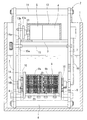
以下、図面に基づき、本発明の実施形態を説明する。このバレルめっき装置は細かい粉末状の被めっき物を電解めっきするものであり、図1および図2に示すように、めっき槽1の上端縁に支持部材2が懸架され、電解めっき浴の上方に設けられた支持部材2の支持台3に、後述するクランクアーム14を往復揺動させる駆動源としてのモータ4と減速機5が配置され、下端部を連結枠6で連結されてめっき浴中に垂下された左右のサイドフレーム7の下部に、左右一対の平行なラックレール8が取り付けられ、被めっき物が投入される筒状のバレル容器9の両端部に、バレル容器9と一体で軸心の回りに回転する歯車輪10が取り付けられて、これらの歯車輪10が左右一対のラックレール8と噛み合って、バレル容器9が軸心と直交方向に転動するようになっている。支持部材2には把手11が設けられ、モータ4と減速機5は、めっき液の飛沫がかからないように、カバー12で覆われている。
Hereinafter, embodiments of the present invention will be described with reference to the drawings. This barrel plating apparatus is for electroplating a fine powder-like object to be plated. As shown in FIG. 1 and FIG. 2, a
前記モータ4と減速機5の出力軸としてのクランク軸13の円板部13aには偏心した突起ピン13bが設けられ、この突起ピン13bに、クランクアーム14が基端側のアーム長手方向に延びる長孔14aで、長手方向にスライド自在に係合され、その下方でサイドフレーム7間に差し渡された支点軸15の支点15aに揺動自在に支持されている。また、めっき浴中に垂下されたクランクアーム14の先端には、バレル容器9の一端側に軸心と同軸上に設けられた円形軸部16を回転自在に把持する二股状の把持部14bが設けられている。
The
したがって、図3(a)、(b)に示すように、前記クランク軸13を一方向へ回転駆動することにより、クランクアーム14が長孔14aで突起ピン13bとスライドしながら支点15aの回りに往復揺動し、その把持部14bで円形軸部16を回転自在に把持されたバレル容器9が、図中に矢印で示すように、歯車輪10でラックレール8上を往復転動するとともに、往方向と復方向とで回転方向が反転し、バレル容器9の下部側の側壁に沿って移動する粉末状の被めっき物の層内に相互流動を生じさせる。
Therefore, as shown in FIGS. 3A and 3B, by rotating the
この実施形態では、クランク軸13を時計回りに回転駆動しており、図3(a)に示すように、突起ピン13bが円板部13aの上側に位置するときは、バレル容器9は左方へ転動し、図3(b)に示すように、突起ピン13bが円板部13aの下側に位置するときは、バレル容器9は右方へ転動する。また、突起ピン13bが円板部13aの上側に位置するときは、クランクアーム14の支点15aから突起ピン13bまでの距離が長くなるので、バレル容器9の転動速度が遅くなり、突起ピン13bが円板部13aの下側に位置するときは、クランクアーム14の支点15aから突起ピン13bまでの距離が短くなるので、バレル容器9の転動速度が速くなる。このように、往方向と復方向とで転動速度が変わることによっても、粉末状の被めっき物の層内での相互流動が活発になる。なお、クランク軸13の回転速度は、バレル容器9に投入される被めっき物の量や相互流動性に応じて、変更可能となっている。
In this embodiment, the
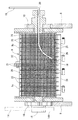
図2および図4に示すように、前記めっき浴中には陽極棒17が吊り下げられ、陰極端子18を先端に取り付けられたフレキシブルな被覆電導線19が、バレル容器9の円形軸部16と反対側に設けられた中心孔20からバレル容器9内に導入されている。バレル容器9内に導かれた電導線19は、バレル容器9の回転に伴ってその下部側の側壁に沿って流動する被めっき物に陰極端子18が接触するように、その先端が下向きに垂れている。
As shown in FIGS. 2 and 4, the
図5および図6に示すように、前記バレル容器9は、中央の分割面で2つの六角筒状の筒部材9a、9bに分割され、これらの筒部材9a、9bが分割面に設けられた各フランジ21を突き合わせて、ねじ22で一体に結合されるとともに、結合された六角筒の一側面が開口部23とされ、開口部23が一体の蓋部材24で閉塞されるようになっている。各筒部材9a、9bと蓋部材24は樹脂で形成され、各筒部材9a、9bの筒面と蓋部材24に設けられた格子状の桟25に、被めっき物よりも細かいメッシュ26が、バレル内面側からインサート成形されている。
As shown in FIGS. 5 and 6, the
上述した実施形態では、バレル容器の車輪を歯車輪、その案内用のレールをラックレールとしたが、これらの車輪とレールは転動時にスリップを生じないものであればよく、いずれか一方または両方の転動面の摩擦係数を大きくしたものとすることもできる。 In the above-described embodiment, the barrel container wheel is a toothed wheel, and the guide rail is a rack rail. However, these wheels and rails only need to cause no slippage during rolling, either one or both The friction coefficient of the rolling surface can be increased.
また、上述した実施形態では、バレル容器を往復転動させるように往復揺動するアームをクランクアームとし、そのアーム長を基端側の長孔で変化させ、先端側の把持部を二股状としたが、先端側の把持部は、円形軸部の全周を把持する環状のものとすることもできる。また、二股状の把持部を延長し、この把持部でアーム長を変化させるようにすることもできる。 Further, in the above-described embodiment, the arm that reciprocally swings so as to reciprocately roll the barrel container is the crank arm, the arm length is changed by the elongated hole on the proximal end side, and the grip portion on the distal end side is bifurcated However, the grip portion on the distal end side may be an annular shape that grips the entire circumference of the circular shaft portion. It is also possible to extend the bifurcated grip and change the arm length at this grip.
1 めっき槽
2 支持部材
3 支持台
4 モータ
5 減速機
6 連結枠
7 サイドフレーム
8 ラックレール
9 バレル容器
9a、9b 筒部材
10 歯車輪
11 把手
12 カバー
13 クランク軸
13a 円板部
13b 突起ピン
14 クランクアーム
14a 長孔
14b 把持部
15 支点軸
15a 支点
16 円形軸部
17 陽極棒
18 陰極端子
19 電導線
20 中心孔
21 フランジ
22 ねじ
23 開口部
24 蓋部材
25 桟
26 メッシュ
DESCRIPTION OF SYMBOLS 1
Claims (6)
Priority Applications (1)
| Application Number | Priority Date | Filing Date | Title |
|---|---|---|---|
| JP2008202685A JP4809878B2 (en) | 2008-08-06 | 2008-08-06 | Barrel plating equipment |
Applications Claiming Priority (1)
| Application Number | Priority Date | Filing Date | Title |
|---|---|---|---|
| JP2008202685A JP4809878B2 (en) | 2008-08-06 | 2008-08-06 | Barrel plating equipment |
Publications (2)
| Publication Number | Publication Date |
|---|---|
| JP2010037605A true JP2010037605A (en) | 2010-02-18 |
| JP4809878B2 JP4809878B2 (en) | 2011-11-09 |
Family
ID=42010457
Family Applications (1)
| Application Number | Title | Priority Date | Filing Date |
|---|---|---|---|
| JP2008202685A Active JP4809878B2 (en) | 2008-08-06 | 2008-08-06 | Barrel plating equipment |
Country Status (1)
| Country | Link |
|---|---|
| JP (1) | JP4809878B2 (en) |
Cited By (4)
| Publication number | Priority date | Publication date | Assignee | Title |
|---|---|---|---|---|
| JP2012097314A (en) * | 2010-11-01 | 2012-05-24 | Kida Seiko Kk | Surface treatment device with non-drainage |
| JP6209668B1 (en) * | 2016-12-22 | 2017-10-04 | 株式会社島谷技研 | Plating equipment |
| CN112587840A (en) * | 2020-12-29 | 2021-04-02 | 曹小爱 | Remote control fire-fighting robot |
| CN112914945A (en) * | 2021-04-08 | 2021-06-08 | 温州智荣健康科技有限公司 | Massage assembly, massage mechanism and massage chair |
Citations (2)
| Publication number | Priority date | Publication date | Assignee | Title |
|---|---|---|---|---|
| JPS5567173A (en) * | 1978-11-13 | 1980-05-21 | Xerox Corp | Selffmatching mesfet and method of manufacturing same |
| JP2006016640A (en) * | 2004-06-30 | 2006-01-19 | Sekisui Chem Co Ltd | Apparatus and method for manufacturing conductive particulate, and conductive particulate |
-
2008
- 2008-08-06 JP JP2008202685A patent/JP4809878B2/en active Active
Patent Citations (2)
| Publication number | Priority date | Publication date | Assignee | Title |
|---|---|---|---|---|
| JPS5567173A (en) * | 1978-11-13 | 1980-05-21 | Xerox Corp | Selffmatching mesfet and method of manufacturing same |
| JP2006016640A (en) * | 2004-06-30 | 2006-01-19 | Sekisui Chem Co Ltd | Apparatus and method for manufacturing conductive particulate, and conductive particulate |
Cited By (6)
| Publication number | Priority date | Publication date | Assignee | Title |
|---|---|---|---|---|
| JP2012097314A (en) * | 2010-11-01 | 2012-05-24 | Kida Seiko Kk | Surface treatment device with non-drainage |
| JP6209668B1 (en) * | 2016-12-22 | 2017-10-04 | 株式会社島谷技研 | Plating equipment |
| JP2018104742A (en) * | 2016-12-22 | 2018-07-05 | 株式会社島谷技研 | Plating device |
| CN112587840A (en) * | 2020-12-29 | 2021-04-02 | 曹小爱 | Remote control fire-fighting robot |
| CN112587840B (en) * | 2020-12-29 | 2021-11-30 | 湖南威平科技发展有限公司 | Remote control fire-fighting robot |
| CN112914945A (en) * | 2021-04-08 | 2021-06-08 | 温州智荣健康科技有限公司 | Massage assembly, massage mechanism and massage chair |
Also Published As
| Publication number | Publication date |
|---|---|
| JP4809878B2 (en) | 2011-11-09 |
Similar Documents
| Publication | Publication Date | Title |
|---|---|---|
| JP4809878B2 (en) | Barrel plating equipment | |
| JP5507145B2 (en) | Opening barrel plating equipment | |
| CN109518203B (en) | Non ferrous metal surface treatment device | |
| CN113774468A (en) | Electroplating device | |
| CN112318712A (en) | Careful uniform stirring mechanism in small amount of concrete bucket | |
| CN106345982B (en) | Magnesium alloy pickup spraying integral machine | |
| CN211568441U (en) | Lifting transmission device | |
| JP5021694B2 (en) | Barrel equipment for plating | |
| CN211886591U (en) | Industrial wastewater treatment device | |
| CN106477076A (en) | A kind of reagent bottle pusher | |
| CN107447252A (en) | A kind of jittering device suitable for PCB electroplating devices | |
| CN210544607U (en) | Novel glue stirring device | |
| JP2648930B2 (en) | Hanging device for electroplating | |
| CN201921972U (en) | Feed anti-reverse device of cold heading forming machine | |
| CN111676507A (en) | Barrel plating device and application method thereof in ceramic electroplating | |
| CN220095134U (en) | Injection molding device | |
| CN106417434B (en) | A kind of flour stranding machine | |
| CN214142048U (en) | Heavy metal stabilization equipment with mixing mechanism for sludge treatment | |
| CN218393368U (en) | Preparation device of controllable nickel nanowire | |
| CN109571953A (en) | A kind of 3D printing equipment of collapse | |
| CN211999957U (en) | Metal workpiece titanium-plating processing device | |
| CN218530680U (en) | Up-down circulation type stirring device | |
| CN217578291U (en) | Filling equipment is used in production of diafenthiuron technical | |
| CN108435049A (en) | A kind of mulser | |
| CN210432762U (en) | Continuous automatic frying machine for flat tea |
Legal Events
| Date | Code | Title | Description |
|---|---|---|---|
| A977 | Report on retrieval |
Free format text: JAPANESE INTERMEDIATE CODE: A971007 Effective date: 20110520 |
|
| A131 | Notification of reasons for refusal |
Free format text: JAPANESE INTERMEDIATE CODE: A131 Effective date: 20110524 |
|
| A521 | Request for written amendment filed |
Free format text: JAPANESE INTERMEDIATE CODE: A523 Effective date: 20110720 |
|
| TRDD | Decision of grant or rejection written | ||
| A01 | Written decision to grant a patent or to grant a registration (utility model) |
Free format text: JAPANESE INTERMEDIATE CODE: A01 Effective date: 20110809 |
|
| A01 | Written decision to grant a patent or to grant a registration (utility model) |
Free format text: JAPANESE INTERMEDIATE CODE: A01 |
|
| A61 | First payment of annual fees (during grant procedure) |
Free format text: JAPANESE INTERMEDIATE CODE: A61 Effective date: 20110819 |
|
| FPAY | Renewal fee payment (event date is renewal date of database) |
Free format text: PAYMENT UNTIL: 20140826 Year of fee payment: 3 |
|
| R150 | Certificate of patent or registration of utility model |
Ref document number: 4809878 Country of ref document: JP Free format text: JAPANESE INTERMEDIATE CODE: R150 Free format text: JAPANESE INTERMEDIATE CODE: R150 |
|
| R250 | Receipt of annual fees |
Free format text: JAPANESE INTERMEDIATE CODE: R250 |
|
| R250 | Receipt of annual fees |
Free format text: JAPANESE INTERMEDIATE CODE: R250 |
|
| R250 | Receipt of annual fees |
Free format text: JAPANESE INTERMEDIATE CODE: R250 |
|
| R250 | Receipt of annual fees |
Free format text: JAPANESE INTERMEDIATE CODE: R250 |
|
| R250 | Receipt of annual fees |
Free format text: JAPANESE INTERMEDIATE CODE: R250 |
|
| R250 | Receipt of annual fees |
Free format text: JAPANESE INTERMEDIATE CODE: R250 |
|
| R250 | Receipt of annual fees |
Free format text: JAPANESE INTERMEDIATE CODE: R250 |
|
| R250 | Receipt of annual fees |
Free format text: JAPANESE INTERMEDIATE CODE: R250 |
|
| R250 | Receipt of annual fees |
Free format text: JAPANESE INTERMEDIATE CODE: R250 |
|
| R250 | Receipt of annual fees |
Free format text: JAPANESE INTERMEDIATE CODE: R250 |