JP2010036953A - Folding container for rolled object - Google Patents
Folding container for rolled object Download PDFInfo
- Publication number
- JP2010036953A JP2010036953A JP2008201478A JP2008201478A JP2010036953A JP 2010036953 A JP2010036953 A JP 2010036953A JP 2008201478 A JP2008201478 A JP 2008201478A JP 2008201478 A JP2008201478 A JP 2008201478A JP 2010036953 A JP2010036953 A JP 2010036953A
- Authority
- JP
- Japan
- Prior art keywords
- roll
- plate
- peripheral
- container
- core tube
- Prior art date
- Legal status (The legal status is an assumption and is not a legal conclusion. Google has not performed a legal analysis and makes no representation as to the accuracy of the status listed.)
- Granted
Links
- 230000002093 peripheral effect Effects 0.000 claims abstract description 71
- 239000000463 material Substances 0.000 claims description 23
- 239000011111 cardboard Substances 0.000 claims description 16
- 239000004033 plastic Substances 0.000 claims description 14
- 229920003023 plastic Polymers 0.000 claims description 14
- 238000004804 winding Methods 0.000 claims description 4
- 238000005096 rolling process Methods 0.000 abstract 1
- 229920005989 resin Polymers 0.000 description 14
- 239000011347 resin Substances 0.000 description 14
- PPBRXRYQALVLMV-UHFFFAOYSA-N Styrene Chemical compound C=CC1=CC=CC=C1 PPBRXRYQALVLMV-UHFFFAOYSA-N 0.000 description 8
- 239000000428 dust Substances 0.000 description 5
- NLHHRLWOUZZQLW-UHFFFAOYSA-N Acrylonitrile Chemical compound C=CC#N NLHHRLWOUZZQLW-UHFFFAOYSA-N 0.000 description 3
- 238000004064 recycling Methods 0.000 description 3
- 239000004743 Polypropylene Substances 0.000 description 2
- XECAHXYUAAWDEL-UHFFFAOYSA-N acrylonitrile butadiene styrene Chemical compound C=CC=C.C=CC#N.C=CC1=CC=CC=C1 XECAHXYUAAWDEL-UHFFFAOYSA-N 0.000 description 2
- 229920000122 acrylonitrile butadiene styrene Polymers 0.000 description 2
- 239000004676 acrylonitrile butadiene styrene Substances 0.000 description 2
- 230000008878 coupling Effects 0.000 description 2
- 238000010168 coupling process Methods 0.000 description 2
- 238000005859 coupling reaction Methods 0.000 description 2
- 239000004794 expanded polystyrene Substances 0.000 description 2
- 239000002184 metal Substances 0.000 description 2
- 238000000034 method Methods 0.000 description 2
- 239000010893 paper waste Substances 0.000 description 2
- 239000011087 paperboard Substances 0.000 description 2
- 229920001707 polybutylene terephthalate Polymers 0.000 description 2
- -1 polypropylene Polymers 0.000 description 2
- 235000017166 Bambusa arundinacea Nutrition 0.000 description 1
- 235000017491 Bambusa tulda Nutrition 0.000 description 1
- 241001330002 Bambuseae Species 0.000 description 1
- 229920000181 Ethylene propylene rubber Polymers 0.000 description 1
- VVQNEPGJFQJSBK-UHFFFAOYSA-N Methyl methacrylate Chemical compound COC(=O)C(C)=C VVQNEPGJFQJSBK-UHFFFAOYSA-N 0.000 description 1
- 235000015334 Phyllostachys viridis Nutrition 0.000 description 1
- 239000004698 Polyethylene Substances 0.000 description 1
- 239000004793 Polystyrene Substances 0.000 description 1
- 229920000800 acrylic rubber Polymers 0.000 description 1
- 239000002390 adhesive tape Substances 0.000 description 1
- 230000002238 attenuated effect Effects 0.000 description 1
- 239000011425 bamboo Substances 0.000 description 1
- 238000005452 bending Methods 0.000 description 1
- 229920006026 co-polymeric resin Polymers 0.000 description 1
- 238000003912 environmental pollution Methods 0.000 description 1
- 229920006248 expandable polystyrene Polymers 0.000 description 1
- 239000010408 film Substances 0.000 description 1
- 239000011888 foil Substances 0.000 description 1
- 239000007788 liquid Substances 0.000 description 1
- 230000004048 modification Effects 0.000 description 1
- 238000012986 modification Methods 0.000 description 1
- 238000000465 moulding Methods 0.000 description 1
- 239000000123 paper Substances 0.000 description 1
- 239000002985 plastic film Substances 0.000 description 1
- 229920006255 plastic film Polymers 0.000 description 1
- 229920003229 poly(methyl methacrylate) Polymers 0.000 description 1
- 229920000058 polyacrylate Polymers 0.000 description 1
- 239000004417 polycarbonate Substances 0.000 description 1
- 229920005668 polycarbonate resin Polymers 0.000 description 1
- 239000004431 polycarbonate resin Substances 0.000 description 1
- 229920013716 polyethylene resin Polymers 0.000 description 1
- 239000004926 polymethyl methacrylate Substances 0.000 description 1
- 229920001155 polypropylene Polymers 0.000 description 1
- 229920005990 polystyrene resin Polymers 0.000 description 1
- 230000001012 protector Effects 0.000 description 1
- 239000002699 waste material Substances 0.000 description 1
- XLYOFNOQVPJJNP-UHFFFAOYSA-N water Substances O XLYOFNOQVPJJNP-UHFFFAOYSA-N 0.000 description 1
- 239000002023 wood Substances 0.000 description 1
Images


Abstract
Description
本発明は、ロール状物用組立容器に関し、更に詳しくは、使用しない時には部材を1枚の板状に薄くすることができるので収納や運搬効率が高く、組立時には組み立てが容易で部材間の結合強度が強く、しかも分解が容易なロール状物用組立容器に関する。 The present invention relates to an assembly container for a roll-like object. More specifically, when not in use, the member can be thinned into a single plate, so that the storage and transport efficiency is high, and the assembly is easy and easy to assemble during assembly. The present invention relates to an assembly container for a roll-shaped object that is strong and easy to disassemble.
従来、ドライレジスト、プラスチックフィルム、金属箔、薄紙等の帯状製品を芯管に巻回してなるロール状物は、該ロール状物の両側から鍔状のプロテクターを当接させてロール状物を箱の床面から浮かせた状態でダンボール箱等の容器に収容され、保管や輸送に供されている。 Conventionally, a roll-shaped product obtained by winding a strip-shaped product such as a dry resist, a plastic film, a metal foil, and thin paper around a core tube is brought into contact with a bowl-shaped protector from both sides of the roll-shaped product. It is housed in a container such as a cardboard box in a state of being floated from the floor, and is used for storage and transportation.
しかしながら、ロール状物のサイズは製品によって異なるため、1種類の通常の容器でロール状物を効率よく収納することはできない。そこで、ロール状物の種類の分だけ異なるサイズの容器を予め作成するか、或いは、大きめの容器を準備してサイズが異なるロール状物を一旦容器に収容した後、容器のどちらか一方の側壁端に当接させ、他の側壁側に生じた空間に発泡スチロール等の緩衝材を詰めて隙間を無くし、容器内でロール状物全体が動かないように保護する方法が採られている。 However, since the size of the roll-like material varies depending on the product, the roll-like material cannot be efficiently stored in one type of normal container. Therefore, a container having a different size corresponding to the type of the roll-shaped object is prepared in advance, or a large container is prepared and a roll-shaped object having a different size is once stored in the container, and then one of the side walls of the container. A method is adopted in which a space formed on the other side wall is brought into contact with the end, and a cushioning material such as foamed polystyrene is filled to eliminate a gap so that the entire roll-shaped object is prevented from moving in the container.
しかしながら、サイズに合わせて様々な大きさの数種類の容器を準備する場合には、保管に多大なスペースが必要になるばかりでなく輸送の効率が悪く、そのために余分な人件費が生じコストアップの要因にもなっていた。 However, when preparing several kinds of containers of various sizes according to the size, not only a large space is required for storage, but also the transportation efficiency is poor, which causes an extra labor cost and increases the cost. It was also a factor.
また、大きめの容器を準備し、空いた隙間に発泡スチロール等の緩衝材を詰める形態では、作業性が極めて悪い上、これら発泡スチロール等はリサイクルされずに、使用後はゴミとして送り先側にて焼却処理されるのが常であり、焼却される際に焼却炉を傷めたり、環境汚染の原因になるという課題があった。
また、リサイクルする場合においても、容器と緩衝材の素材が異なるため、分別してリサイクルする必要があり、リサイクルのコストが上昇し、リサイクルを困難にする原因となっていた。
In addition, when a large container is prepared and cushioning material such as expanded polystyrene is packed in the open gap, the workability is extremely poor, and these expanded polystyrene is not recycled and is incinerated on the destination side as waste after use. There is a problem that the incinerator is damaged when it is incinerated and causes environmental pollution.
Also, when recycling, since the materials of the container and the buffer material are different, it is necessary to separate and recycle, which increases the cost of recycling and makes recycling difficult.
そこで、伸ばすと1枚の薄い板状になるような部材を組み立てて容器を作成することにより、組立前の容器の収容スペースを小さくしてコストダウンを図る試みもなされている。例えば、四角柱状に折り曲げられた本体部の係合溝に、一対の第1側板を係合した廃紙材製通箱が提案されている(特許文献1)。しかしながら、このような箱は、本体を形成する底板、蓋板、第2側板を薄くすれば係合溝が浅すぎて第1側板が外れやすくなり強度が弱く、十分な強度を有するように係合溝を深くしようとすれば本体を形成する底板、蓋板、第2側板が厚くなりすぎて収納に要するスペースが大きくなるばかりでなく、重くて扱いにくくなる。
また、この廃紙材製通箱では底板、蓋板、第2側板が四角柱状に折り曲げられて初めて係合溝と第1側板が完全に係合するが、この状態では箱が密閉されているため、中にロール状物を入れることができない。そこで蓋板が開いた状態で、底板、第2側板のみで第1側板と係合してから箱のなかにロール状物を収容するが、この場合は、第1側板と第2側板の結合強度が十分でないので、第2側板が不意に開いてしまう危険性があり、これを防ぐため第2側板を手などで支えて開かないようにしておく必要が生じ、作業が煩雑となる。
Further, in this waste paper material pass box, the engagement groove and the first side plate are completely engaged only after the bottom plate, the cover plate, and the second side plate are bent into a quadrangular column shape. In this state, the box is sealed. For this reason, it is not possible to put a roll-like material inside. Then, with the cover plate open, the bottom plate and the second side plate are engaged with the first side plate and then the roll-shaped object is accommodated in the box. In this case, the first side plate and the second side plate are combined. Since the strength is not sufficient, there is a risk that the second side plate will open unexpectedly. In order to prevent this, it is necessary to support the second side plate with a hand so as not to open it, and the work becomes complicated.
本発明は上記従来の課題を解決するために、使用しない時には板状になるような、保管のためのスペースが少なくて済み搬送が容易な部材を組み立ててなる容器において、板状の部材を厚くすることなく部材間の結合強度を強くすることができ、且つ容器として利用する際は、容易に組立が可能であるとともに、不要時には容易に組立前の状態に分解できる組立容器を提供することを目的とする。 In order to solve the above-mentioned conventional problems, the present invention increases the thickness of a plate-like member in a container formed by assembling a member that has a small storage space and can be easily transported, such as a plate shape when not in use. The present invention provides an assembly container that can increase the bonding strength between members without being used, and can be easily assembled when used as a container, and can be easily disassembled before assembly when not required. Objective.
上記目的を達成するために、本発明の請求項1は、帯状製品を芯管に巻回してなるロール状物を保護、収納するロール状物用組立容器であって、2枚の周面板と2枚の端面板とからなり、周面板は、ロール状物の径よりも幅広で帯状製品の幅よりも長い方形の中央面と、その幅方向両側にヒンジ部を介して連設された2面の横側面からなると共に、横側面の幅の和は中央面の幅以上であり、端面板は、その中央部にロール状物の芯管を保持する保持孔が穿設され、端面板の上下縁の両横付近、及び周面板横側面の開放縁の両横付近には咬合可能なスリットが設けられていることを特徴とするロール状物用組立容器を内容とする。 In order to achieve the above object, claim 1 of the present invention is an assembly container for a roll-like product that protects and stores a roll-like product obtained by winding a strip-shaped product around a core tube, and includes two peripheral plates and It consists of two end face plates, and the peripheral face plate is connected to the center surface of a rectangle wider than the diameter of the roll-like product and longer than the width of the belt-like product, and 2 connected to both sides in the width direction via hinges. The end face plate is formed with a holding hole for holding the core tube of the roll-like material at the center portion of the end face plate. An assembly container for a roll-like object is characterized in that an occlusal slit is provided in the vicinity of both sides of the upper and lower edges and in the vicinity of both sides of the open edge of the side surface of the peripheral plate.
本発明の請求項2は、端面板中央に穿設された保持孔よりも径が大きい頭部と、収納するロール状物の芯管の内径と径がほぼ等しい芯管保持部とを有するキャップが端面板の保持孔に嵌着されることを特徴とする請求項1に記載のロール状物用組立容器を内容とする。
本発明の請求項3は、周面板の両横側面の幅の和は中央面の幅より大きく、端面板の上下縁のいずれか一方の縁に設けられたスリットは、このスリットに対向する他方の縁に設けられたスリットと、周面板約1枚分の厚みだけずらして設けられていることを特徴とする請求項1又は請求項2に記載のロール状物用組立容器を内容とする。
According to a third aspect of the present invention, the sum of the widths of both lateral side surfaces of the peripheral plate is larger than the width of the central surface, and the slit provided on one of the upper and lower edges of the end plate is the other facing the slit. The assembly container for rolls according to
本発明の請求項4は、周面板及び端面板がプラスチックダンボール製であり、スリットはプラスチックダンボールのリブと平行に、且つリブを切り欠かないように形成されていることを特徴とする請求項1乃至請求項3のいずれか1項に記載のロール状物用組立容器を内容とする。
According to a fourth aspect of the present invention, the peripheral surface plate and the end surface plate are made of plastic corrugated cardboard, and the slit is formed in parallel with the rib of the plastic corrugated cardboard so as not to cut out the rib. The assembly container for rolls according to any one of
本発明のロール状物用組立容器は、2枚の周面板と2枚の端面板からなり、周面板は展開すれば(伸ばせば)1枚の薄い板状となるので、周面板も端面板も保管のためのスペースが極めて小さくて済み、収納や運搬が極めて効率的に行えるとともに、径が同じであれば端面板を変えずに周面板だけを変えることにより様々な長さのロール状物に対応できるため、部品点数を減らすことが出来る。また、周面板と端面板はそれぞれに設けられたスリットを咬合させて結合するので、部材間の結合強度が強い。さらに、1枚の周面板をコ字状に折り曲げて、その両横部分に2枚の端面板を結合させ、その上からもう1枚の周面板をコ字状に折り曲げて組み合わせることにより、容易に組み立てることが出来るとともに、これと逆の操作をすることにより容易に分解することも出来る。また、1枚の周面板をコ字状に折り曲げ、その両端部分に2枚の端面板を結合させることにより、通常の容器で蓋を取り除いた状態となるため、周面板や端面板を手で支えることなく、容易にロール状物を出し入れすることが可能である、そして、この状態から更に一方の端面板を取り外せば、上側のみならず横側も開放されるので、横側の開放部からロール状物の出し入れをすることも可能である。 The roll-like object assembly container of the present invention comprises two peripheral plates and two end plates. When the peripheral plate is unfolded (when extended), it becomes one thin plate, so the peripheral plate is also an end plate. The space for storage is very small, and it can be stored and transported very efficiently. If the diameter is the same, rolls of various lengths can be obtained by changing only the peripheral plate without changing the end plate. Therefore, the number of parts can be reduced. In addition, since the peripheral surface plate and the end surface plate are coupled by engaging the slits provided in each, the coupling strength between the members is strong. Furthermore, it is easy to fold one peripheral plate into a U-shape, join two end plates to both sides, and fold another peripheral plate into a U-shape and combine it. Can be assembled, and can be easily disassembled by performing the reverse operation. In addition, by folding one peripheral plate into a U-shape and joining the two end plates to both ends thereof, the lid is removed with a normal container, so the peripheral plate and end plate can be removed by hand. It is possible to easily take in and out the roll without supporting, and if one end face plate is further removed from this state, not only the upper side but also the side will be opened, so from the side open part It is also possible to take in and out the roll.
保持孔よりも径が大きい頭部と、収納するロール状物の芯管の内径と径がほぼ等しい芯管保持部とを有するキャップを端面板の保持孔に嵌着すれば、芯管の中空部に芯管保持部を挿入することにより、端面から芯管が突出していないようなロール状物を好適に保持することができる。 If a cap having a head having a diameter larger than that of the holding hole and a core tube holding part having a diameter substantially equal to the inner diameter of the core tube of the roll-shaped object to be accommodated is fitted into the holding hole of the end face plate, the core tube is hollow. By inserting the core tube holding part into the part, it is possible to suitably hold a roll-like object in which the core tube does not protrude from the end face.
周面板の両横側面の幅の和を中央面の幅より大きくするとともに、端面板の上下縁のいずれか一方の縁に設けられたスリットを、このスリットに対向する他方の縁に設けられたスリットと、周面板約1枚分の厚みだけずらして設けるようにすれば、対向する周面板の横側面は一部重複するので、横側面の隙間からゴミやホコリ等が入り込んでロール状物を汚すような恐れがなくなる。 The sum of the widths of both lateral sides of the peripheral surface plate is made larger than the width of the central surface, and a slit provided on one of the upper and lower edges of the end surface plate is provided on the other edge facing this slit. If the slit and the circumferential plate are shifted by the thickness of about one sheet, the lateral side surfaces of the opposing circumferential plate partially overlap, so that dust or dust enters the gap between the lateral sides, and rolls are removed. No fear of getting dirty.
周面板及び端面板がプラスチックダンボール製とし、スリットはプラスチックダンボールのリブと平行に、且つリブを切り欠かないように形成すれば、スリットを形成してもプラスチックダンボールの強度は殆ど減衰せず、壊れにくくなり耐久性が向上する。 If the peripheral plate and end plate are made of plastic cardboard and the slits are formed in parallel with the ribs of the plastic cardboard and do not cut out the ribs, the strength of the plastic cardboard is hardly attenuated even if the slits are formed. It becomes difficult to improve durability.
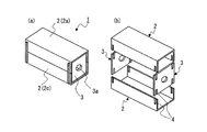
本発明のロール状物用組立容器1は、図1〜図3に記載した実施例1で代表的に示すとおり、帯状製品を芯管R1に巻回してなるロール状物Rを保護、収納するロール状物用組立容器1であって、2枚の周面板2と2枚の端面板3とからなり、周面板2は、ロール状物の径L1よりも幅広で帯状製品の幅L2よりも長い方形の中央面2aと、その幅方向両側にヒンジ部2bを介して連設された2面の横側面2cからなると共に、横側面2cの幅の和は中央面2aの幅以上であり、端面板3は、その中央部にロール状物の芯管R1を保持する保持孔3aが穿設され、端面板3の上下縁3bの両横付近、及び周面板2横側面2cの開放縁2dの両横付近には咬合可能なスリット4が設けられていることを特徴とする。
The roll-shaped product assembly container 1 of the present invention protects and stores a roll-shaped product R formed by winding a strip-shaped product around a core tube R1, as typically shown in Example 1 described in FIGS. An assembly container 1 for a roll-shaped object, which is composed of two
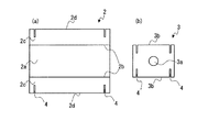
本発明における周面板2は、図2(a)に示す通り、方形の中央面2aの幅方向両側に、ヒンジ部2bを介して横側面2cが連設されてなり、横側面2cの開放縁2dの両横付近にスリット4が設けられている。
この周面板2は図1に示す通り、ヒンジ部2bで折り曲げて略コ字状とした2枚の周面板2を組み合わせて、好ましくは断面略正方形の4角柱状とし、ロール状物用組立容器1の周面とされる。本実施例においては横側面2cの幅の和と中央面の幅が等しくなっているので、それぞれの2枚の周面板2のそれぞれの横側面2cの開放縁2dを付き合わせるように組み立てれば、丁度、断面が略正方形の4角柱状となるが、横側面2cの幅の和を中央面の幅よりも大きくして、対向する周面板2の横側面2cを幾分重複させることにより断面が略正方形になるようにしてもよい。
As shown in FIG. 2 (a), the
As shown in FIG. 1, the
本発明における端面板3は、図2(b)に示す通り、全体視が略矩形であって、その中央部にはロール状物Rの芯管を保持するための保持孔3aが穿設され、その上縁及び下縁3b(以下、上下縁3bと略す)の両横付近にスリット4が設けられている。
この端面板3は図1に示す通り、4角柱状に組み付けられた周面板2の両端側に配置され、ロール状物用組立容器1の端面とされる。
As shown in FIG. 2 (b), the
As shown in FIG. 1, the
本発明のロール状物用組立容器1は、2枚の周面板2と2枚の端面板3からなり、周面板は伸ばせば1枚の薄い板状となるので、周面板も端面板も積み重ねれば非常にコンパクトに纏まり、保管や運搬のためのスペースが極めて小さくて済むので、収納や運搬を極めて効率的に行うことができる。
また、限られた種類の部品で様々な長さのロール状物Rに対応でき、例えば、ロール状物の径が同じであれば端面板3を変えずに周面板2だけを変更することにより長さが異なるロール状物Rを収納できる容器1とすることができるため、多種類のロール状物Rを扱う場合でも部品点数を減らすことができ、管理コストを下げることができる。
The roll-like assembly container 1 of the present invention comprises two
Moreover, it can respond | correspond to the roll-shaped object R of various length with a limited kind of components, for example, if the diameter of a roll-shaped object is the same, by changing only the
周面板2及び端面板3には、上記の通りそれぞれにスリット4が設けられているが、図1に示したとおり、これらの周面板2及び端面板3はスリット4を互いに咬合させることにより結合するとともに、全てのスリット4を咬合させることにより本発明のロール状物用組立容器1が完成する。
詳述すれば、1枚の周面板2をコ字状に折り曲げ、その両横部分のスリット4と端面板3側のスリット4を咬合させて2枚の端面板を結合させ、その上からもう1枚の周面板2をコ字状に折り曲げてから、前述と同様にスリット4同士を咬合させて組み合わせることにより、容易に組み立てることが出来る。また、使用後は、上側の周面板2を引き抜いてから、端面板3を引き抜くという単純な方法で、容易に分解することも出来る。
The
More specifically, one
本発明において、スリット4の幅は、通常、周面板2又は端面板3の厚さ程度とされるが、周面板側と端面板側のいずれか一方、又は両方のスリット4を周面板2又は端面板3の厚さよりも僅かに狭くし、弾性を利用して圧入挟着させることにより結合の強度を上げてもよい。
スリット4の位置は、周面板横側面2cの開放縁2dの両横付近、及び端面板3の上下縁3bの両横付近であるが、端部に近すぎる場合はスリット4と端部の間が細くなり過ぎ、強度が低下するので、材料の強度及び使用条件を考慮して破損しない程度の間隔を保持したほうが好ましい。
In the present invention, the width of the
The positions of the
周面板2及び端面板3の材質は特に限定されず、ABS(アクリロニトリル- ブタジエン- スチレン共重合樹脂)、AAS樹脂(アクリロニトリル/アクリルゴム/スチレン)、AES樹脂(アクリロニトリル/エチレンプロピレンゴム/スチレン)、AS樹脂(アクリロニトリル/スチレン)、PS樹脂(ポリスチレン樹脂)、PMMA樹脂、PVC樹脂、MS樹脂(メチルメタクリレート/スチレン樹脂)、PP(ポリプロピレン樹脂)、PE(ポリエチレン樹脂)、PBT(ポリブチレンテレフタレート樹脂)およびPC樹脂(ポリカーボネート樹脂)等の樹脂、紙やダンボール、樹脂フィルムをラミネートした紙やダンボール、木材、竹材、金属等、内容物を保護できるような材質である限りどのようなものでも使用できるが、軽量、安価、成形のし易さ等の観点から、樹脂製とするのが好ましい。
特に、平行に延設された多数のリブ5を介して2枚のプラスチック薄板を貼り合せた、所謂プラスチックダンボールを使用すれば、軽量で且つ十分な強度を有しており、さらに耐衝撃性及び耐水性に優れているため好ましい。また、本発明におけるスリット4をリブ5の間の部分に設け、リブ5を切り欠かないようにすれば、周面板2及び端面板3の強度を殆ど低下させることがないので好ましい。
The material of the
In particular, if a so-called plastic corrugated cardboard in which two plastic thin plates are bonded through a large number of ribs 5 extending in parallel is used, it has a light weight and sufficient strength, and further has an impact resistance and It is preferable because of its excellent water resistance. Further, it is preferable to provide the
上記のように組み立てられたロール状物用組立容器1は、端面板3に穿設された保持孔3aにロール状物Rの芯管R1を挿通し、ロール状物Rを保持する。
本発明のロール状物用組立容器1にロール状物Rを収容するには、例えば、先ず、図3に記載されているように、組み立てられたロール状物用組立容器1から上側の周面板2を取り外すことにより、又は1枚の周面板2と2枚の端面板3を組み付けることにより、上側が開放された状態にし、次いで、ロール状物Rを容器内に入れて保持孔3aに芯管R1を挿通し、最後に残りの周面板2を組み付ける。このようなロール状物用組立容器1では、1枚の周面板2に端面板3を組み付けた段階で、周面板2の形状が略コ字状に保持されるため、例えば特許文献1の箱のように、収容作業中に横側面2cが不意に開く恐れがなく、容易且つ確実にロール状物Rを容器内に収容できる。
なお、周面板の中央面2aはロール状物の径L1よりも幅広で帯状製品の幅L2よりも長い方形であり、対向する周面板2の横側面2cが組み合わされた面もほぼ同様とされるので、ロール状物Rの表面はいずれの周面にも擦れることがない。
なお、必要に応じ、ロール状物Rと容器内壁面との間に緩衝材を介装してもよい。また、上側の周面板2の横側面2cと下側の周面板2の横側面2cとの会合面に粘着テープで接着することもできる。
The roll-shaped product assembly container 1 assembled as described above holds the roll-shaped product R by inserting the core tube R1 of the roll-shaped product R through the holding
In order to accommodate the roll-shaped material R in the roll-shaped material assembly container 1 of the present invention, for example, first, as shown in FIG. 2 is removed, or one
In addition, the
In addition, you may interpose a buffer material between the roll-shaped object R and a container inner wall surface as needed. Moreover, it can also adhere | attach to the meeting surface of the
また、芯管R1がロール状物Rの端面から突出しておらず、保持孔3aに芯管R1を挿通出来ないような場合には、図4(b)に示したような、保持孔3aよりも径が大きい頭部6aと、芯管R1の内径と径がほぼ等しい芯管保持部6bとを有するキャップ6を用いてロール状物Rを保持する。この場合、図4(a)に示したように、芯管保持部6bを保持孔3aに通して芯管R1の中に嵌入することにより、ロール状物Rは容器内に好適に収容される。
When the core tube R1 does not protrude from the end face of the roll R and the core tube R1 cannot be inserted into the holding
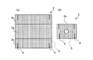
次に、本発明のロール状物用組立容器1の実施例2について、図5及び図6に基づいて説明する。
本実施例では、材質としてプラスチックダンボールが用いられるとともに、横側面の幅の和は中央面の幅よりも広く、組み立てたときに横側面が一部重複するようにした例である。なお、図5(a)(b)において、直線状の一点鎖線はリブ5を示す。
Next, a second embodiment of the roll-like assembly container 1 of the present invention will be described with reference to FIGS.
In the present embodiment, plastic corrugated cardboard is used as the material, and the sum of the widths of the side surfaces is wider than the width of the center surface, and the side surfaces partially overlap when assembled. In FIGS. 5A and 5B, a linear alternate long and short dash line indicates the rib 5.
図5(a)は本実施例で用いる周面板2を示す。この周面板2では、スリット4がダンボールプラスチックのリブ5の間に、このリブと平行に設けられており、リブ5は切り欠かれていない。また、ヒンジ部2bでは折り曲げの邪魔にならぬよう、リブの一部が切削されている。
FIG. 5A shows the
図5(b)は本実施例で用いる端面板3を示す。この端面板3でも、スリット4がダンボールプラスチックのリブ5の間に、このリブと平行に設けられており、リブ5は切り欠かれていない。但し、本実施例の場合、上下縁3bにそれぞれ設けられたスリットは完全には対向しておらず、周面板2約1枚分の厚みだけずらして設けられている。具体的には、図5(b)における左右の縁から4本目のリブ5を境に、下縁では該リブ5の右側、上縁では該リブの左側にスリット4が設けられている。
FIG. 5B shows the
なお、前述の通り、スリット4の幅は周面板2又は端面板3の厚さ、即ち本実施例の場合はプラスチックダンボールの厚さと略同じであるが、市販のプラスチックダンボールにおけるリブ5の間隔は、通常の場合、プラスチックダンボールの厚さよりも若干広いので、リブ5を傷つけないようにスリット4を形成するのは容易である。
As described above, the width of the
図5(a)の周面板2と図5(b)の端面板3を組み付けると、図6(a)に示したように、横側面2cの一部が重複した状態になる。このため横側面2cの間からゴミやホコリ等が入り込んでロール状物Rの表面を汚す恐れが無くなる。
なお、図6(b)に示したように、上側の周面板2をやや大きくすると共に、下側の周面板2を上側の周面板2の下に嵌り込む程度の大きさにすると、ゴミやホコリ等の侵入を阻止する他、上側の周面板2の横側面2cが下側の周面板2の横側面2cを覆うので、例えば雨水等の液体が上からかかったとしても、容器1内には侵入しないため好ましい。
When the
As shown in FIG. 6B, if the upper
以上、本発明の好ましい態様を実施例に基づいて説明したが、本発明はこれら実施例のみに限定されるものではなく、本発明の要旨から逸脱することなく種々のバリエーションが可能であることは云うまでもない。
例えば、図示した円形の保持孔3aに代えて、U字形のものも採用でき、この場合は、芯管R1が突出したロール状物Rを収納する場合はU字形の上部開口部から突出した芯管R1を導入することにより容易に収納することができる。
As mentioned above, although the preferable aspect of this invention was demonstrated based on the Example, this invention is not limited only to these Examples, A various variation is possible without deviating from the summary of this invention. Needless to say.
For example, instead of the
叙上のとおり、本発明のロール状物用組立容器によれば、収納時には部材を1枚の板状に薄くすることができ収納効率が高いとともに、組立時における部材間の結合強度が強く、組立分解が容易であるので、ロール状物の保存、運搬のために使用する容器として頗る有用である。 As described above, according to the assembly container for a roll-like object of the present invention, the member can be thinned into a single plate at the time of storage, the storage efficiency is high, and the coupling strength between the members at the time of assembly is strong, Since assembly and disassembly is easy, it is useful as a container used for storing and transporting rolls.
1 ロール状物用組立容器
2 周面板
2a 中央面
2b ヒンジ部
2c 横側面
2d 開放縁
3 端面板
3a 保持孔
3b 上下縁
4 スリット
5 リブ
6 キャップ
6a 頭部
6b 芯管保持部
R ロール状物
R1 芯管
L1 ロール状物の径
L2 帯状製品の幅
DESCRIPTION OF SYMBOLS 1 Assembly container for roll-shaped
Claims (4)
周面板は、ロール状物の径よりも幅広で帯状製品の幅よりも長い方形の中央面と、その幅方向両側にヒンジ部を介して連設された2面の横側面からなると共に、横側面の幅の和は中央面の幅以上であり、
端面板は、その中央部にロール状物の芯管を保持する保持孔が穿設され、
端面板の上下縁の両横付近、及び周面板横側面の開放縁の両横付近には咬合可能なスリットが設けられていることを特徴とするロール状物用組立容器。 A roll-shaped product assembly container for protecting and storing a roll-shaped product formed by winding a strip-shaped product around a core tube, comprising two peripheral plates and two end plates.
The peripheral surface plate is composed of a rectangular central surface that is wider than the diameter of the roll-shaped object and longer than the width of the belt-shaped product, and two lateral surfaces that are continuously provided via hinges on both sides in the width direction. The sum of the widths of the side faces is greater than or equal to the width of the center face,
The end face plate has a holding hole for holding the core tube of the roll-like material in the center thereof,
An assembly container for roll-like objects, characterized in that slits that can be engaged are provided in the vicinity of both sides of the upper and lower edges of the end face plate and in the vicinity of both sides of the open edge of the side surface of the peripheral face plate.
収納するロール状物の芯管の内径と径がほぼ等しい芯管保持部とを有するキャップが端面板の保持孔に嵌着されることを特徴とする請求項1に記載のロール状物用組立容器。 A head having a diameter larger than the holding hole drilled in the center of the end face plate;
2. A roll-shaped object assembly according to claim 1, wherein a cap having a core tube holding portion having a diameter substantially equal to the inner diameter of the core tube of the roll-shaped material to be accommodated is fitted into the holding hole of the end face plate. container.
端面板の上下縁のいずれか一方の縁に設けられたスリットは、このスリットに対向する他方の縁に設けられたスリットと、周面板約1枚分の厚みだけずらして設けられていることを特徴とする請求項1又は請求項2に記載のロール状物用組立容器。 The sum of the widths of both lateral sides of the peripheral plate is larger than the width of the center plane,
The slit provided on either one of the upper and lower edges of the end face plate is shifted from the slit provided on the other edge facing this slit by a thickness of about one peripheral plate. The assembly container for roll-like objects according to claim 1 or 2, characterized in that
Priority Applications (1)
| Application Number | Priority Date | Filing Date | Title |
|---|---|---|---|
| JP2008201478A JP5183347B2 (en) | 2008-08-05 | 2008-08-05 | Assembly container for rolls |
Applications Claiming Priority (1)
| Application Number | Priority Date | Filing Date | Title |
|---|---|---|---|
| JP2008201478A JP5183347B2 (en) | 2008-08-05 | 2008-08-05 | Assembly container for rolls |
Publications (2)
| Publication Number | Publication Date |
|---|---|
| JP2010036953A true JP2010036953A (en) | 2010-02-18 |
| JP5183347B2 JP5183347B2 (en) | 2013-04-17 |
Family
ID=42009909
Family Applications (1)
| Application Number | Title | Priority Date | Filing Date |
|---|---|---|---|
| JP2008201478A Active JP5183347B2 (en) | 2008-08-05 | 2008-08-05 | Assembly container for rolls |
Country Status (1)
| Country | Link |
|---|---|
| JP (1) | JP5183347B2 (en) |
Cited By (2)
| Publication number | Priority date | Publication date | Assignee | Title |
|---|---|---|---|---|
| CN102874478A (en) * | 2012-09-19 | 2013-01-16 | 铜陵其利电子材料有限公司 | Metalized film roll supporting device |
| CN107380621A (en) * | 2017-08-17 | 2017-11-24 | 广东美的暖通设备有限公司 | Packing case |
Citations (6)
| Publication number | Priority date | Publication date | Assignee | Title |
|---|---|---|---|---|
| JP3047494U (en) * | 1997-09-25 | 1998-04-14 | 株式会社ニューかいか | Assembled food packaging container |
| JP2002080087A (en) * | 2000-09-08 | 2002-03-19 | Kawatake Electronics Co Ltd | Container for rolled object |
| JP3088236U (en) * | 2002-01-07 | 2002-09-06 | 株式会社エコロジー開発 | Rolled product transport support |
| JP2002284281A (en) * | 2001-03-28 | 2002-10-03 | Matsushita Electric Ind Co Ltd | Storage device of rolled winding having winding shaft |
| JP2003054557A (en) * | 2001-08-08 | 2003-02-26 | Nippon Matai Co Ltd | Corrugated board box for containing rolled article |
| JP2005096810A (en) * | 2003-09-25 | 2005-04-14 | Dainippon Printing Co Ltd | Manufacturing method of electrode plate tape roll |
-
2008
- 2008-08-05 JP JP2008201478A patent/JP5183347B2/en active Active
Patent Citations (6)
| Publication number | Priority date | Publication date | Assignee | Title |
|---|---|---|---|---|
| JP3047494U (en) * | 1997-09-25 | 1998-04-14 | 株式会社ニューかいか | Assembled food packaging container |
| JP2002080087A (en) * | 2000-09-08 | 2002-03-19 | Kawatake Electronics Co Ltd | Container for rolled object |
| JP2002284281A (en) * | 2001-03-28 | 2002-10-03 | Matsushita Electric Ind Co Ltd | Storage device of rolled winding having winding shaft |
| JP2003054557A (en) * | 2001-08-08 | 2003-02-26 | Nippon Matai Co Ltd | Corrugated board box for containing rolled article |
| JP3088236U (en) * | 2002-01-07 | 2002-09-06 | 株式会社エコロジー開発 | Rolled product transport support |
| JP2005096810A (en) * | 2003-09-25 | 2005-04-14 | Dainippon Printing Co Ltd | Manufacturing method of electrode plate tape roll |
Cited By (2)
| Publication number | Priority date | Publication date | Assignee | Title |
|---|---|---|---|---|
| CN102874478A (en) * | 2012-09-19 | 2013-01-16 | 铜陵其利电子材料有限公司 | Metalized film roll supporting device |
| CN107380621A (en) * | 2017-08-17 | 2017-11-24 | 广东美的暖通设备有限公司 | Packing case |
Also Published As
| Publication number | Publication date |
|---|---|
| JP5183347B2 (en) | 2013-04-17 |
Similar Documents
| Publication | Publication Date | Title |
|---|---|---|
| US20080011637A1 (en) | Display Package with Plastic Sleeve and Interlocking Insert Tray | |
| JP5099149B2 (en) | Packing container | |
| JP4898038B2 (en) | Resin box | |
| JP5183347B2 (en) | Assembly container for rolls | |
| KR101061587B1 (en) | Packing box | |
| JP4940450B2 (en) | Separate type outer box | |
| JP5864225B2 (en) | Case for roll products | |
| JP5466069B2 (en) | Packaging case | |
| JP6120485B2 (en) | Roll product protector | |
| JP2003192081A (en) | Packaging container and packaging method for electronic material film roll | |
| KR100888759B1 (en) | Package box and Box Blanks | |
| JP3191352U (en) | Transport packaging container | |
| JP3139765U (en) | Buffer holding container for toner storage container | |
| JP2003104357A (en) | Box made of resin | |
| JPH0920329A (en) | Collapsible container | |
| US10717563B2 (en) | Reusable bulk-sized shipping box | |
| JP3220999U (en) | Cardboard box | |
| JP2008087828A (en) | Sheet structure | |
| JP6332613B2 (en) | Transport packaging container | |
| KR20230016269A (en) | Packaging box | |
| JPH068223U (en) | Bottle storage box | |
| JP2004301920A (en) | Packaging container for rolled photosensitive material | |
| JP2003312656A (en) | Assembling container for rolled item and knockdown container containing rolled item | |
| JP2007246108A (en) | Synthetic resin folding box | |
| JP3160078U (en) | Stacking adapter |
Legal Events
| Date | Code | Title | Description |
|---|---|---|---|
| A621 | Written request for application examination |
Free format text: JAPANESE INTERMEDIATE CODE: A621 Effective date: 20110627 |
|
| A977 | Report on retrieval |
Free format text: JAPANESE INTERMEDIATE CODE: A971007 Effective date: 20121019 |
|
| A131 | Notification of reasons for refusal |
Free format text: JAPANESE INTERMEDIATE CODE: A131 Effective date: 20121106 |
|
| A521 | Request for written amendment filed |
Free format text: JAPANESE INTERMEDIATE CODE: A523 Effective date: 20121127 |
|
| TRDD | Decision of grant or rejection written | ||
| A01 | Written decision to grant a patent or to grant a registration (utility model) |
Free format text: JAPANESE INTERMEDIATE CODE: A01 Effective date: 20121225 |
|
| A61 | First payment of annual fees (during grant procedure) |
Free format text: JAPANESE INTERMEDIATE CODE: A61 Effective date: 20130115 |
|
| R150 | Certificate of patent or registration of utility model |
Free format text: JAPANESE INTERMEDIATE CODE: R150 Ref document number: 5183347 Country of ref document: JP Free format text: JAPANESE INTERMEDIATE CODE: R150 |
|
| FPAY | Renewal fee payment (event date is renewal date of database) |
Free format text: PAYMENT UNTIL: 20160125 Year of fee payment: 3 |
|
| R250 | Receipt of annual fees |
Free format text: JAPANESE INTERMEDIATE CODE: R250 |
|
| R250 | Receipt of annual fees |
Free format text: JAPANESE INTERMEDIATE CODE: R250 |
|
| R250 | Receipt of annual fees |
Free format text: JAPANESE INTERMEDIATE CODE: R250 |
|
| RD02 | Notification of acceptance of power of attorney |
Free format text: JAPANESE INTERMEDIATE CODE: R3D02 |
|
| R250 | Receipt of annual fees |
Free format text: JAPANESE INTERMEDIATE CODE: R250 |
|
| R250 | Receipt of annual fees |
Free format text: JAPANESE INTERMEDIATE CODE: R250 |
|
| R250 | Receipt of annual fees |
Free format text: JAPANESE INTERMEDIATE CODE: R250 |
|
| R250 | Receipt of annual fees |
Free format text: JAPANESE INTERMEDIATE CODE: R250 |
|
| R250 | Receipt of annual fees |
Free format text: JAPANESE INTERMEDIATE CODE: R250 |
|
| R250 | Receipt of annual fees |
Free format text: JAPANESE INTERMEDIATE CODE: R250 |