JP2010036835A - Vehicle lighting unit - Google Patents
Vehicle lighting unit Download PDFInfo
- Publication number
- JP2010036835A JP2010036835A JP2008205221A JP2008205221A JP2010036835A JP 2010036835 A JP2010036835 A JP 2010036835A JP 2008205221 A JP2008205221 A JP 2008205221A JP 2008205221 A JP2008205221 A JP 2008205221A JP 2010036835 A JP2010036835 A JP 2010036835A
- Authority
- JP
- Japan
- Prior art keywords
- mirror
- vehicle
- light source
- semiconductor light
- light
- Prior art date
- Legal status (The legal status is an assumption and is not a legal conclusion. Google has not performed a legal analysis and makes no representation as to the accuracy of the status listed.)
- Granted
Links
- 239000004065 semiconductor Substances 0.000 claims abstract description 32
- 239000003086 colorant Substances 0.000 claims abstract description 19
- 230000003595 spectral effect Effects 0.000 claims abstract description 7
- 238000001514 detection method Methods 0.000 claims description 3
- 238000007493 shaping process Methods 0.000 claims 1
- 230000005540 biological transmission Effects 0.000 abstract 1
- 238000005286 illumination Methods 0.000 description 11
- 238000010586 diagram Methods 0.000 description 5
- 239000000758 substrate Substances 0.000 description 4
- 230000001678 irradiating effect Effects 0.000 description 3
- 230000003287 optical effect Effects 0.000 description 3
- 238000003384 imaging method Methods 0.000 description 2
- 230000007246 mechanism Effects 0.000 description 2
- 230000009471 action Effects 0.000 description 1
- 230000008859 change Effects 0.000 description 1
- 230000003111 delayed effect Effects 0.000 description 1
- 230000000694 effects Effects 0.000 description 1
- 230000007613 environmental effect Effects 0.000 description 1
- 230000009191 jumping Effects 0.000 description 1
- 230000004048 modification Effects 0.000 description 1
- 238000012986 modification Methods 0.000 description 1
- 230000000737 periodic effect Effects 0.000 description 1
- 230000002093 peripheral effect Effects 0.000 description 1
- 238000002310 reflectometry Methods 0.000 description 1
- 230000004044 response Effects 0.000 description 1
Images


Classifications
-
- B—PERFORMING OPERATIONS; TRANSPORTING
- B60—VEHICLES IN GENERAL
- B60Q—ARRANGEMENT OF SIGNALLING OR LIGHTING DEVICES, THE MOUNTING OR SUPPORTING THEREOF OR CIRCUITS THEREFOR, FOR VEHICLES IN GENERAL
- B60Q1/00—Arrangement of optical signalling or lighting devices, the mounting or supporting thereof or circuits therefor
- B60Q1/02—Arrangement of optical signalling or lighting devices, the mounting or supporting thereof or circuits therefor the devices being primarily intended to illuminate the way ahead or to illuminate other areas of way or environments
- B60Q1/24—Arrangement of optical signalling or lighting devices, the mounting or supporting thereof or circuits therefor the devices being primarily intended to illuminate the way ahead or to illuminate other areas of way or environments for lighting other areas than only the way ahead
- B60Q1/245—Searchlights, e.g. adjustable from within the vehicle
-
- B—PERFORMING OPERATIONS; TRANSPORTING
- B60—VEHICLES IN GENERAL
- B60Q—ARRANGEMENT OF SIGNALLING OR LIGHTING DEVICES, THE MOUNTING OR SUPPORTING THEREOF OR CIRCUITS THEREFOR, FOR VEHICLES IN GENERAL
- B60Q1/00—Arrangement of optical signalling or lighting devices, the mounting or supporting thereof or circuits therefor
- B60Q1/02—Arrangement of optical signalling or lighting devices, the mounting or supporting thereof or circuits therefor the devices being primarily intended to illuminate the way ahead or to illuminate other areas of way or environments
- B60Q1/04—Arrangement of optical signalling or lighting devices, the mounting or supporting thereof or circuits therefor the devices being primarily intended to illuminate the way ahead or to illuminate other areas of way or environments the devices being headlights
- B60Q1/14—Arrangement of optical signalling or lighting devices, the mounting or supporting thereof or circuits therefor the devices being primarily intended to illuminate the way ahead or to illuminate other areas of way or environments the devices being headlights having dimming means
- B60Q1/1415—Dimming circuits
- B60Q1/1423—Automatic dimming circuits, i.e. switching between high beam and low beam due to change of ambient light or light level in road traffic
- B60Q1/143—Automatic dimming circuits, i.e. switching between high beam and low beam due to change of ambient light or light level in road traffic combined with another condition, e.g. using vehicle recognition from camera images or activation of wipers
-
- F—MECHANICAL ENGINEERING; LIGHTING; HEATING; WEAPONS; BLASTING
- F21—LIGHTING
- F21S—NON-PORTABLE LIGHTING DEVICES; SYSTEMS THEREOF; VEHICLE LIGHTING DEVICES SPECIALLY ADAPTED FOR VEHICLE EXTERIORS
- F21S41/00—Illuminating devices specially adapted for vehicle exteriors, e.g. headlamps
- F21S41/10—Illuminating devices specially adapted for vehicle exteriors, e.g. headlamps characterised by the light source
- F21S41/12—Illuminating devices specially adapted for vehicle exteriors, e.g. headlamps characterised by the light source characterised by the type of emitted light
- F21S41/125—Coloured light
-
- F—MECHANICAL ENGINEERING; LIGHTING; HEATING; WEAPONS; BLASTING
- F21—LIGHTING
- F21S—NON-PORTABLE LIGHTING DEVICES; SYSTEMS THEREOF; VEHICLE LIGHTING DEVICES SPECIALLY ADAPTED FOR VEHICLE EXTERIORS
- F21S41/00—Illuminating devices specially adapted for vehicle exteriors, e.g. headlamps
- F21S41/10—Illuminating devices specially adapted for vehicle exteriors, e.g. headlamps characterised by the light source
- F21S41/14—Illuminating devices specially adapted for vehicle exteriors, e.g. headlamps characterised by the light source characterised by the type of light source
- F21S41/141—Light emitting diodes [LED]
- F21S41/147—Light emitting diodes [LED] the main emission direction of the LED being angled to the optical axis of the illuminating device
-
- F—MECHANICAL ENGINEERING; LIGHTING; HEATING; WEAPONS; BLASTING
- F21—LIGHTING
- F21S—NON-PORTABLE LIGHTING DEVICES; SYSTEMS THEREOF; VEHICLE LIGHTING DEVICES SPECIALLY ADAPTED FOR VEHICLE EXTERIORS
- F21S41/00—Illuminating devices specially adapted for vehicle exteriors, e.g. headlamps
- F21S41/60—Illuminating devices specially adapted for vehicle exteriors, e.g. headlamps characterised by a variable light distribution
- F21S41/65—Illuminating devices specially adapted for vehicle exteriors, e.g. headlamps characterised by a variable light distribution by acting on light sources
- F21S41/663—Illuminating devices specially adapted for vehicle exteriors, e.g. headlamps characterised by a variable light distribution by acting on light sources by switching light sources
-
- F—MECHANICAL ENGINEERING; LIGHTING; HEATING; WEAPONS; BLASTING
- F21—LIGHTING
- F21S—NON-PORTABLE LIGHTING DEVICES; SYSTEMS THEREOF; VEHICLE LIGHTING DEVICES SPECIALLY ADAPTED FOR VEHICLE EXTERIORS
- F21S41/00—Illuminating devices specially adapted for vehicle exteriors, e.g. headlamps
- F21S41/60—Illuminating devices specially adapted for vehicle exteriors, e.g. headlamps characterised by a variable light distribution
- F21S41/67—Illuminating devices specially adapted for vehicle exteriors, e.g. headlamps characterised by a variable light distribution by acting on reflectors
- F21S41/675—Illuminating devices specially adapted for vehicle exteriors, e.g. headlamps characterised by a variable light distribution by acting on reflectors by moving reflectors
-
- B—PERFORMING OPERATIONS; TRANSPORTING
- B60—VEHICLES IN GENERAL
- B60Q—ARRANGEMENT OF SIGNALLING OR LIGHTING DEVICES, THE MOUNTING OR SUPPORTING THEREOF OR CIRCUITS THEREFOR, FOR VEHICLES IN GENERAL
- B60Q2300/00—Indexing codes for automatically adjustable headlamps or automatically dimmable headlamps
- B60Q2300/30—Indexing codes relating to the vehicle environment
- B60Q2300/32—Road surface or travel path
-
- B—PERFORMING OPERATIONS; TRANSPORTING
- B60—VEHICLES IN GENERAL
- B60Q—ARRANGEMENT OF SIGNALLING OR LIGHTING DEVICES, THE MOUNTING OR SUPPORTING THEREOF OR CIRCUITS THEREFOR, FOR VEHICLES IN GENERAL
- B60Q2300/00—Indexing codes for automatically adjustable headlamps or automatically dimmable headlamps
- B60Q2300/40—Indexing codes relating to other road users or special conditions
- B60Q2300/45—Special conditions, e.g. pedestrians, road signs or potential dangers
-
- F—MECHANICAL ENGINEERING; LIGHTING; HEATING; WEAPONS; BLASTING
- F21—LIGHTING
- F21Y—INDEXING SCHEME ASSOCIATED WITH SUBCLASSES F21K, F21L, F21S and F21V, RELATING TO THE FORM OR THE KIND OF THE LIGHT SOURCES OR OF THE COLOUR OF THE LIGHT EMITTED
- F21Y2113/00—Combination of light sources
- F21Y2113/10—Combination of light sources of different colours
- F21Y2113/13—Combination of light sources of different colours comprising an assembly of point-like light sources
- F21Y2113/17—Combination of light sources of different colours comprising an assembly of point-like light sources forming a single encapsulated light source
Landscapes
- Engineering & Computer Science (AREA)
- General Engineering & Computer Science (AREA)
- Mechanical Engineering (AREA)
- Physics & Mathematics (AREA)
- Microelectronics & Electronic Packaging (AREA)
- Optics & Photonics (AREA)
- Led Device Packages (AREA)
- Non-Portable Lighting Devices Or Systems Thereof (AREA)
- Lighting Device Outwards From Vehicle And Optical Signal (AREA)
Abstract
Description
本発明は、複数色の半導体光源からの光を混合し、車両周辺の照射対象に応じた色の光を照射する車両用灯具に関する。 The present invention relates to a vehicular lamp that mixes light from a plurality of colors of semiconductor light sources and emits light of a color according to an irradiation target around the vehicle.
従来、光源に出射色が異なる複数のLEDを用いた車両用灯具が知られている。例えば、特許文献1には、ロービーム用灯具とハイビーム用灯具とフォグランプ用灯具のそれぞれに赤、緑、青のLEDを設け、灯具ごとにLEDを選択的に点灯し、LEDの光を適宜に混ぜ合わせ、車両周辺の複数の対象域を異なる色の光で照明する車両用灯具が記載されている。 Conventionally, a vehicular lamp using a plurality of LEDs having different emission colors as a light source is known. For example, in Patent Document 1, red, green, and blue LEDs are provided for each of a low beam lamp, a high beam lamp, and a fog lamp lamp, and the LEDs are selectively turned on for each lamp, and the light of the LEDs is appropriately mixed. In addition, a vehicular lamp that illuminates a plurality of target areas around the vehicle with light of different colors is described.
特許文献2には、車両前方の歩行者をカメラで撮像し、歩行者の位置と色を検出し、複数色のLEDをモータで検出位置に向け、LEDの光を混ぜ合わせ、着衣の色と異なる着色光で歩行者を見やすく照明する車両用灯具が提案されている。
ところが、特許文献1の車両用灯具によると、対象域ごとに専用の灯具を割り当て、各灯具に複数のLEDを設けているため、灯具全体として多数の光源が必要になるという問題点があった。特許文献2の車両用前照灯によると、歩行者を検出した時点でモータを駆動しているので、着色光を照射するタイミングが遅れるという不都合があった。また、LEDが対象物を向く位相でモータを停止させるため、車両前方に複数の対象物が存在する場合、モータを再駆動する必要があり、実質的に複数の対象物を同時に照射できないという問題点があった。
However, according to the vehicular lamp of Patent Document 1, a dedicated lamp is allocated to each target area, and a plurality of LEDs are provided for each lamp, and thus there is a problem that a large number of light sources are required as a whole lamp. . According to the vehicle headlamp of
本発明の目的は、上記課題を解決し、少数の半導体光源を用い、照射色を瞬時に切り替え、異なる色の光を複数の照射対象に同時に照射できる車両用灯具を提供することにある。 An object of the present invention is to provide a vehicular lamp that solves the above-mentioned problems, uses a small number of semiconductor light sources, instantaneously switches the irradiation color, and can simultaneously irradiate a plurality of irradiation objects with different colors.
上記課題を解決するために、本発明の車両用灯具は、異なる色の光を出射する複数の半導体光源と、車両周辺の照射対象に応じて少なくとも一つの半導体光源を選択する選択手段と、半導体光源の出射光を車両周辺に反射するミラーと、ミラーを往復回動する走査用アクチュエータと、ミラーと照射対象との相対位置を検知する検知手段と、ミラーが照射対象と向き合う位相で選択された半導体光源を点灯する制御手段とを備えたことを特徴とする。なお、本発明において、照射対象とは、歩行者や障害物等の路面上対象物、交差点や踏切等の道路施設であり、以下でこれらを総称して対象物と呼ぶ。 In order to solve the above-described problems, a vehicle lamp according to the present invention includes a plurality of semiconductor light sources that emit light of different colors, a selection unit that selects at least one semiconductor light source according to an irradiation target around the vehicle, and a semiconductor A mirror that reflects light emitted from the light source to the periphery of the vehicle, a scanning actuator that reciprocates the mirror, detection means that detects the relative position of the mirror and the irradiation target, and a phase at which the mirror faces the irradiation target are selected. And a control means for turning on the semiconductor light source. In addition, in this invention, irradiation objects are road surface objects, such as a pedestrian and an obstruction, and road facilities, such as an intersection and a railroad crossing, These are generically called an object below.
ここで、走査用アクチュエータは、ミラーを高速で駆動し、ミラーの反射光を車両周辺の所定の照射範囲でスキャンする。このため、照射範囲に複数の対象物が含まれている場合、ミラーが各対象物に向き合う位相で半導体光源を点灯することにより、人間の目には複数の対象物が同時に照明されているように見える。なお、この種の作用が得られる走査用アクチュエータとしては、例えば、電磁駆動方式、圧電駆動方式または静電駆動方式のアクチュエータを好ましく使用できる。 Here, the scanning actuator drives the mirror at high speed, and scans the reflected light of the mirror within a predetermined irradiation range around the vehicle. For this reason, when a plurality of objects are included in the irradiation range, the semiconductor light source is turned on at a phase where the mirror faces each object, so that a plurality of objects are illuminated simultaneously to the human eye. Looks like. As a scanning actuator capable of obtaining this kind of action, for example, an electromagnetic drive type, piezoelectric drive type or electrostatic drive type actuator can be preferably used.
また、本発明の車両用灯具は、ミラーの反射光で運転者に注意を喚起できるように、半導体光源の出射光を成形するスリットを備え、ミラーが車両周辺にスポット光を反射することを特徴とする。半導体光源としては、車両用としてLEDを好ましく使用できるが、着色スポット光をシャープに形成できる点でレーザー光源も使用可能である。 In addition, the vehicular lamp of the present invention includes a slit that shapes the emitted light of the semiconductor light source so that the driver can be alerted by the reflected light of the mirror, and the mirror reflects the spot light around the vehicle. And As a semiconductor light source, an LED can be preferably used for a vehicle, but a laser light source can also be used in that a colored spot light can be formed sharply.
本発明は、LEDの光を有効に利用し、対象物に綺麗なスポット光を照射できる手段を提供する。具体的には、半導体光源にLEDを用い、複数色のLEDを反射鏡の第1焦点近くに配置し、反射鏡の第2焦点近くにスリットを配置し、LEDの出射光を反射鏡の楕円反射面で反射させ、スリットを通してミラーで偏向させ、レンズで投影するという手段を採用できる。 The present invention provides a means that can effectively use the light of an LED and irradiate an object with a beautiful spot light. Specifically, an LED is used as a semiconductor light source, LEDs of multiple colors are arranged near the first focal point of the reflecting mirror, a slit is arranged near the second focal point of the reflecting mirror, and the emitted light of the LED is an ellipse of the reflecting mirror. It is possible to adopt a means of reflecting on a reflecting surface, deflecting with a mirror through a slit, and projecting with a lens.
車両用灯具が照射する光の色は、複数色の半導体光源からの光を適宜に混ぜ合わせることで、対象物に応じて多様に変化させることができる。対象物を見やすく照明するために、本発明の車両用灯具は、選択手段が対象物の分光反射率特性に応じて半導体光源を選択することを特徴とする。つまり、対象物の反射率が高い波長の光線を多く含むような光を出射する半導体光源を選択することにより、対象物を見やすく照明できる。 The color of light emitted by the vehicular lamp can be varied in various ways depending on the object by appropriately mixing light from a plurality of colors of semiconductor light sources. In order to easily illuminate an object, the vehicular lamp of the present invention is characterized in that the selection means selects a semiconductor light source according to the spectral reflectance characteristics of the object. That is, the object can be easily illuminated by selecting a semiconductor light source that emits light that includes many light beams having a wavelength with high reflectivity.
また、対象物を背景中でより見やすく照明するために、本発明の車両用灯具は、選択手段が対象物とその背景の分光反射率特性に応じて半導体光源を選択することを特徴とする。例えば、夜間走行時に対象物が人の顔を含み、背景が黒の場合、マゼンタ色の光を照射する半導体光源を選択できる。昼間走行時に対象物が人の顔を含み、背景が白の場合、白色光を照射する半導体光源を選択できる。 Moreover, in order to illuminate the object more easily in the background, the vehicular lamp of the present invention is characterized in that the selecting means selects the semiconductor light source in accordance with the object and the spectral reflectance characteristics of the background. For example, when the object includes a human face and the background is black when traveling at night, a semiconductor light source that emits magenta light can be selected. When the object includes a human face and the background is white during daytime driving, a semiconductor light source that emits white light can be selected.
自車両と対象物との相対位置、角度、距離等に応じて半導体光源を選択し、照射色を制御することも可能である。例えば、自車両から対象物までの距離が長い場合に、対象物を発見しやすい色(マゼンタ系)で照射し、ドライバーに気付かせ、対象物が接近するのに伴って、照射光を自然色(白)へ徐々に変化させるという制御を行うことができる。さらに、半導体光源の選択と点消灯とを組み合わせた制御も可能である。例えば、自車両が前方の対象物と衝突する可能性が高いときに、半導体光源の照射光を通常走行時よりも目立つ色に切り替え、同時に、半導体光源を点滅させて、ドライバーの注意を喚起するような制御を行うことができる。 It is also possible to select the semiconductor light source in accordance with the relative position, angle, distance, etc. between the host vehicle and the object and control the irradiation color. For example, when the distance from the vehicle to the object is long, the object is illuminated with a color that makes it easy to find the object (magenta), and the driver is made aware of it. Control can be performed to gradually change to (white). Furthermore, control combining the selection of the semiconductor light source and turning on / off is also possible. For example, when there is a high possibility that the vehicle will collide with an object ahead, the light emitted from the semiconductor light source is switched to a more prominent color than during normal driving, and at the same time, the semiconductor light source flashes to alert the driver. Such control can be performed.
なお、対象物を識別するために、車両用灯具に車載カメラやカーナビシステムを組み合わせて使用することも可能である。この場合、選択手段がカメラの撮像データ、または、カーナビシステムの地図データに基づいて半導体光源を選択し、制御手段が選択された光源の点消灯と駆動電流とを制御することで、車両用灯具の照射色を多様に切り替えることができる。 In addition, in order to identify a target object, it is also possible to use a vehicle lamp in combination with a vehicle-mounted camera or a car navigation system. In this case, the selection unit selects the semiconductor light source based on the imaging data of the camera or the map data of the car navigation system, and the control unit controls the turning on / off of the selected light source and the driving current, thereby the vehicle lamp Various illumination colors can be switched.
本発明の車両用灯具によれば、半導体光源の光をミラーで反射し、走査用アクチュエータで高速スキャンするので、例えば赤、緑、青の3つの半導体光源を用いて車両周辺の任意の領域を複数色の光で多様に照明できるとともに、ミラーが対象物と向き合う位相で照射色を瞬時に切り替え、異なる色の光を複数の対象物に同時に照射し、ドライバーによる視認性能を向上高めることができるという優れた効果を奏する。 According to the vehicular lamp of the present invention, the light of the semiconductor light source is reflected by the mirror and is scanned at a high speed by the scanning actuator. For example, an arbitrary region around the vehicle can be formed using three semiconductor light sources of red, green and blue It can illuminate variously with multiple colors of light, and the illumination color can be switched instantaneously at the phase where the mirror faces the object, and different colors of light can be irradiated simultaneously on the object, improving the driver's visibility. There is an excellent effect.
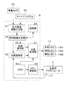
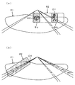
以下、本発明を車両用前照灯に具体化した一実施形態を図面に基づいて説明する。図1は車両用前照灯のハウジングを水平に破断して内部の構成を示す。図2は前照灯の光学システムを外観的に示す。図3は前照灯のスポット光照射機構を示す。図4は前照灯の制御回路を示す。図5は前照灯の照射色切替動作を示す。図6(a)は車両前方の複数の対象物を同時照射するときの前照灯の動作を示す。図6(b)は交差点を照射するときの前照灯の動作を示す。 Hereinafter, an embodiment in which the present invention is embodied in a vehicle headlamp will be described with reference to the drawings. FIG. 1 shows an internal configuration of a vehicle headlamp housing that is horizontally broken. FIG. 2 shows the optical system of the headlamp in appearance. FIG. 3 shows a spot light irradiation mechanism of a headlamp. FIG. 4 shows a headlight control circuit. FIG. 5 shows the irradiation color switching operation of the headlamp. FIG. 6A shows the operation of the headlamp when simultaneously irradiating a plurality of objects in front of the vehicle. FIG. 6B shows the operation of the headlamp when irradiating the intersection.
図1に示すように、この車両用前照灯1は車体の前部に設置されるハウジング2を備え、ハウジング2の前面に透光カバー3が設けられ、ハウジング2の略中央部に走査用アクチュエータ4が設置されている。走査用アクチュエータ4の側方には光源カバー5と制御回路6とが設けられ、走査用アクチュエータ4の前方に投影レンズ7が配設されている。光源カバー5には反射鏡8が組み合わされ、反射鏡8と走査用アクチュエータ4との間にスリット板9が配置されている。
As shown in FIG. 1, the vehicle headlamp 1 includes a
図2に示すように、走査用アクチュエータ4の基板11は四角環状に形成され、基板11の内側に回動体12が垂直なトーションバー13で支持されている。回動体12の表面にはミラー14が形成され、回動体12の左右両側に永久磁石15が設けられている。基板11および回動体12にはコイル(図示略)が配線され、トーションバー13と直交する磁界中でコイルに流れる電流の大きさと向きを制御することにより、ミラー14が電磁力によって回動体12と一体に左右に往復回動される。
As shown in FIG. 2, the
図2、図3に示すように、反射鏡8の内側には、楕円反射面8aがミラー14に向かって開口するように形成されている。反射鏡8の第1焦点F1の近傍には一つまたは複数の光源ユニット17が設置され、光源ユニット17に異なる色の光を出射する複数のLED18、例えば、赤色LED18Rと緑色LED18Gと青色LED18Bとが配設されている。また、反射鏡8の第二焦点F2の近傍にはスリット板9が配置され、スリット板9にLED12の出射光を成形するスリット19が形成されている。
As shown in FIGS. 2 and 3, an elliptical reflecting
そして、LED12の出射光が反射鏡8の楕円反射面18aで反射し、スリット19を通ってミラー14で偏向し、ミラー14からの反射光が投影レンズ7を透過して透光カバー3から車両前方へ照射される。このとき、ミラー14がスリット19の形状に応じたスポット光Sを反射し、走査用アクチュエータ4がミラー14を高速で駆動して、スポット光Sを車両前方の所定の照明範囲(図3に鎖線で囲まれた範囲)でスキャンするようになっている。
Then, the light emitted from the
ここで、例えば、3つのLED18を同時に点灯した場合、スリット19は第二焦点F2で混ざり合った3色の集光束Mの周縁部をカットし、中心部のみをミラー14に入射させる。したがって、車両の通常走行時に、照明範囲の全体を綺麗な白色スポット光Sで照明でき、対象物を検知したときには、その対象物に鮮明な着色スポット光Sを照射することができる。また、光源ユニット17の周囲が反射鏡8で被覆されているので、LED18の拡散光をスリット19に通してミラー14で効率よく反射させることもできる。
Here, for example, when the three
図4に示すように、制御回路6は、複数のLED18(R,G,B)の駆動電流を個別に制御する光源制御部21、走査用アクチュエータ4のコイル電流を制御するミラー制御部22、前照灯1の制御プログラムを含む各種情報を記憶する記憶部23、制御プログラムを実行するCPU24、車載カメラ25とカーナビシステム26から車両周辺の走行環境情報を入力する走行環境情報入力部27、走行環境情報に基づいて前照灯1の照明範囲を決める照明範囲決定部28、照明範囲に含まれる対象物に応じて一つまたは複数のLED18を選択する光源選択部29、対象物とミラー14との相対位置を計算する位置演算部30を備えている。
As shown in FIG. 4, the
ここで、照明範囲決定部28は、車載カメラ25の撮像データおよびカーナビシステム26の地図データを記憶部23から読み出したアルゴリズムで解析し、対象物を含む広さの照明範囲を決定する。光源選択部29は、解析データに基づいて対象物の種類や色、対象物とその背景の分光反射率特性に応じた照射色を決定し、この色を作り出すに必要なLED18を選び出す。位置演算部30は、解析データから対象物の位置を認識し、対象物の位置と走査用アクチュエータ4の位置検出器31から入力したミラー14の現在位置とを照合し、ミラー14が対象物と向き合う位相で光源制御部21に動作指令を出力する。そして、この動作指令に応答し、光源制御部21が光源選択部28で選択されたLED18を点灯し、その駆動電流を制御するようになっている。
Here, the illumination
上記構成の車両用前照灯1によれば、3つのLED18を用いて、車両前方の任意の領域を複数色の光で多様に照明することができる。例えば、図5(a)に示すように、赤、緑、青のLED18R,18G,18Bを一斉に点灯し、車両前方で白色のスポット光Swをスキャンして、照明範囲の全体を通常走行に適した白色光で照明できる。図5(b)に示すように、赤、緑のLED18R,18Gを点灯し、照明範囲の一部を黄色のスポット光Syで照明し、運転者の注意を喚起できる。図5(c)に示すように、赤、青のLED18R,18Bを点灯し、赤紫(マゼンタ)色のスポット光Smで車両前方の歩行者を見やすく照明することができる。
According to the vehicle headlamp 1 having the above-described configuration, it is possible to illuminate various areas in front of the vehicle with a plurality of colors using the three
また、この実施形態の車両用灯具1によれば、光源選択部28が対象物およびその背景の分光反射率特性に応じてLED18を選択し、対象物で反射しやすい波長の光線を多く含むような光を照射し、その対象物を車両前方の背景中で見やすく照明することができる。この点を以下の実験結果に従って説明する。表1に示す<実験結果A>では、黒色スクリーンを背景とし、前照灯モデルから人の顔にマゼンタ色光と白色光とを交互に照射し、モデル側の実験者による顔と背景の見え方を評価した。表2に示す<実験結果B>では、白色スクリーンを背景とし、同じ条件下で顔と背景の見え方を評価した。
Further, according to the vehicular lamp 1 of this embodiment, the light

<実験結果A>に示すとおり、背景が黒の場合、照射光の色に係りなく、背景は黒く見え、人の顔は肌色よりもマゼンタ色の方が目立ちやすい。このため、夜間走行中に歩行者を撮像したときには、赤、青のLED18R,18Bを選択し、マゼンタ色のスポット光Smを照射することで、歩行者を暗い背景中で見やすく照明できる。<実験結果B>に示すように、背景が白の場合は、背景が照射光の色に染まって見えるため、人の顔は背景と同じマゼンタ色よりも背景と異なる肌色の方が目立ちやすい。したがって、昼間走行中に歩行者を撮像したときには、赤、緑、青のLED18R,18G,18Bを選択して、白色のスポット光Swを照射することで、その歩行者を明るい背景中で見やすく照明できる。
As shown in <Experimental result A>, when the background is black, the background looks black regardless of the color of the irradiation light, and the human face is more conspicuous in magenta than skin color. For this reason, when a pedestrian is imaged during night driving, the red and
また、この実施形態の車両用灯具1によれば、ミラー14の周期運動中に照射色を瞬時に切り替え、異なる色の光を複数の対象物に同時に照射することもできる。例えば、図6(a)に示すように、車載カメラ25が歩行者O1と障害物O2を撮像したときに、ミラー14が歩行者O1と向き合う位相で、照射色をマゼンタ色に切り替え、ミラー14が障害物O2と向き合う位相で、照射色を黄色に切り替え、両方の対象物O1,O2を異なる色のスポット光Sm,Syで同時に照射することができる。図6(b)に示すように、カーナビシステム26が交差点O3を検出した場合に、ミラー14が交差点O3と向き合う位相で照射色を白色から黄色に切り替え、黄色のスポット光Syで運転者の注意を喚起し、歩行者O1の飛び出しに備えることができる。
Moreover, according to the vehicular lamp 1 of this embodiment, it is possible to instantaneously switch the irradiation color during the periodic movement of the
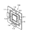
本発明は、上記実施例に限定されるものではなく、以下に例示するように、発明の趣旨を逸脱しない範囲で、灯具各部の構成を適宜に変更して実施することも可能である。図7は二種類の光源ユニットを備えた車両用前照灯を示し、図8はこの前照灯の配光パターンを例示する。図9は二台の走査用アクチュエータを備えた車両用前照灯を示す。図10は走査用アクチュエータの変更例を示す。 The present invention is not limited to the above-described embodiment, and can be implemented by appropriately changing the configuration of each part of the lamp without departing from the spirit of the invention as illustrated below. FIG. 7 shows a vehicular headlamp including two types of light source units, and FIG. 8 illustrates a light distribution pattern of the headlamp. FIG. 9 shows a vehicle headlamp having two scanning actuators. FIG. 10 shows a modification of the scanning actuator.
図7に示す車両用前照灯41では、ハウジング42の内側にメイン灯具43とサブ灯具44が設置されている。メイン灯具43はバルブ46、遮光板47、投影レンズ48を備え、サブ灯具44は前記実施例と同様に構成されている。この前照灯41によれば、図8(a)に示すように、メイン灯具43で車両前方の広範囲に全体配光パターンP1を形成し、サブ灯具44で補助配光パターンP2を全体配光パターンP1の一部に重なるように形成できる。図8(b)に示すように、ミラー14の回動軸を傾け、補助配光パターンP2を斜状に形成し、道路の路肩部分O4を全体配光パターンP1中でより明るく照明することもできる。
In the
図9に示す車両用前照灯51では、メイン灯具53の走査用アクチュエータ4に大型ミラー55が設けられ、サブ灯具54の走査用アクチュエータ4に小型ミラー56が設けられている。そして、大型ミラー55が光源ユニット57からの白色LED光をスキャンし、車両前方に全体配光パターンP1(図8参照)を形成し、小型ミラー56が複数色のLED光をスキャンして補助配光パターンP2を形成できるようになっている。なお、サブ灯具54をメイン灯具53から切り離し、前照灯ハウジング52の外部、例えば、フロントウインドウの内側や車体の側面などに設置することもできる。
In the
図10に示す走査用アクチュエータ58は、基板11上に内外二つの回動体60,61を互いに直交する方向へ回動可能に備え、内側回動体60の表面にミラー14が設けられ、ミラー14を直交2軸方向に往復回動して、車両周辺に多様な配光パターンを形成できるようになっている。なお、電磁駆動方式の走査用アクチュエータ4,58にかえ、静電駆動方式のアクチュエータを使用することも可能である。
The
1 車両用前照灯
4 走査用アクチュエータ
5 光源ユニット
6 制御回路
8 反射鏡
14 ミラー
18 LED
19 スリット
21 光源制御部
25 車載カメラ
26 カーナビシステム
28 光源選択部
29 位置演算部
DESCRIPTION OF SYMBOLS 1
DESCRIPTION OF
Claims (5)
Priority Applications (1)
| Application Number | Priority Date | Filing Date | Title |
|---|---|---|---|
| JP2008205221A JP5271002B2 (en) | 2008-08-08 | 2008-08-08 | Vehicle lighting |
Applications Claiming Priority (1)
| Application Number | Priority Date | Filing Date | Title |
|---|---|---|---|
| JP2008205221A JP5271002B2 (en) | 2008-08-08 | 2008-08-08 | Vehicle lighting |
Publications (2)
| Publication Number | Publication Date |
|---|---|
| JP2010036835A true JP2010036835A (en) | 2010-02-18 |
| JP5271002B2 JP5271002B2 (en) | 2013-08-21 |
Family
ID=42009810
Family Applications (1)
| Application Number | Title | Priority Date | Filing Date |
|---|---|---|---|
| JP2008205221A Expired - Fee Related JP5271002B2 (en) | 2008-08-08 | 2008-08-08 | Vehicle lighting |
Country Status (1)
| Country | Link |
|---|---|
| JP (1) | JP5271002B2 (en) |
Cited By (33)
| Publication number | Priority date | Publication date | Assignee | Title |
|---|---|---|---|---|
| JP2011222238A (en) * | 2010-04-08 | 2011-11-04 | Stanley Electric Co Ltd | Headlight for vehicle |
| JP2012076716A (en) * | 2010-10-06 | 2012-04-19 | Stanley Electric Co Ltd | Light source controller of vehicle lighting fixture |
| EP2578452A1 (en) | 2011-10-06 | 2013-04-10 | Koito Manufacturing Co., Ltd. | Vehicle spot lamp control device and vehicle spot lamp system |
| EP2631122A1 (en) | 2012-02-24 | 2013-08-28 | Koito Manufacturing Co., Ltd. | Headlamp apparatus and headlamp control system |
| DE102012205438A1 (en) * | 2012-04-03 | 2013-10-10 | Bayerische Motoren Werke Aktiengesellschaft | Lighting device for a motor vehicle |
| WO2013149766A1 (en) * | 2012-04-03 | 2013-10-10 | Bayerische Motoren Werke Aktiengesellschaft | Illumination apparatus for a motor vehicle |
| CN103492792A (en) * | 2011-04-22 | 2014-01-01 | 株式会社小糸制作所 | Optical unit |
| JP2014065499A (en) * | 2014-01-24 | 2014-04-17 | Stanley Electric Co Ltd | Headlight for vehicle |
| WO2014162683A1 (en) | 2013-04-04 | 2014-10-09 | 株式会社小糸製作所 | Vehicle lamp fitting |
| CN104110628A (en) * | 2013-04-22 | 2014-10-22 | 株式会社小糸制作所 | Vehicular Lamp |
| FR3006746A1 (en) * | 2013-06-11 | 2014-12-12 | Valeo Vision | PROJECTOR FOR A MOTOR VEHICLE COMPRISING A LASER LIGHT SOURCE |
| WO2015019555A1 (en) | 2013-08-09 | 2015-02-12 | 株式会社小糸製作所 | Vehicle lamp |
| JP2015038885A (en) * | 2014-10-23 | 2015-02-26 | スタンレー電気株式会社 | Vehicle headlamp |
| EP2851611A3 (en) * | 2010-05-12 | 2015-04-08 | OSRAM GmbH | Headlight module |
| WO2015133302A1 (en) * | 2014-03-03 | 2015-09-11 | 株式会社小糸製作所 | Vehicle lamp and vehicle lamp control system |
| JP2015164828A (en) * | 2014-03-03 | 2015-09-17 | 株式会社小糸製作所 | Vehicle lamp and vehicle lamp control system |
| JP2015170564A (en) * | 2014-03-10 | 2015-09-28 | スタンレー電気株式会社 | Vehicular lighting fixture |
| EP2541130A3 (en) * | 2011-06-29 | 2015-09-30 | Sharp Kabushiki Kaisha | Light-projecting device, and vehicle headlamp including light-projecting device |
| EP2962559A1 (en) * | 2014-07-03 | 2016-01-06 | odelo GmbH | Motor vehicle light with light for preventing accidents involving wild animals and method for operating a wild animal accident prevention light independent of the driving state |
| CZ306151B6 (en) * | 2015-02-11 | 2016-08-24 | Varroc Lighting Systems, s.r.o. | Lighting installation |
| EP3059491A1 (en) * | 2015-02-17 | 2016-08-24 | Stanley Electric Co., Ltd. | Vehicle lighting fixture |
| WO2016157765A1 (en) * | 2015-03-31 | 2016-10-06 | パナソニックIpマネジメント株式会社 | Illumination device |
| JPWO2016072484A1 (en) * | 2014-11-07 | 2017-04-27 | 大日本印刷株式会社 | Optical device, vehicle equipped with optical device, and lighting device |
| EP3168526A1 (en) * | 2015-11-12 | 2017-05-17 | Toyota Jidosha Kabushiki Kaisha | Vehicular headlamp |
| JP2017119469A (en) * | 2015-12-28 | 2017-07-06 | 株式会社 オルタステクノロジー | Scanning headlight, control method of scanning headlight, and program |
| EP3196545A1 (en) * | 2016-01-25 | 2017-07-26 | Stanley Electric Co., Ltd. | Vehicular lamp |
| EP3210825A1 (en) * | 2016-02-18 | 2017-08-30 | Audi AG | Lighting device for a motor vehicle, system with the lighting device and method for operating a lighting device |
| CN107202299A (en) * | 2017-05-15 | 2017-09-26 | 深圳市德辰光电科技有限公司 | A kind of multifunctional car light and its manufacture method |
| EP3270042A1 (en) * | 2016-07-08 | 2018-01-17 | LG Electronics Inc. | Control device mounted on vehicle and method for controlling the same |
| EP2551154A3 (en) * | 2011-07-25 | 2018-03-21 | Sharp Kabushiki Kaisha | Illumination device and vehicle headlamp including the illumination device |
| JP2019006192A (en) * | 2017-06-22 | 2019-01-17 | 株式会社小糸製作所 | Vehicular lighting fixture |
| JP2019010908A (en) * | 2017-06-29 | 2019-01-24 | 本田技研工業株式会社 | Work machine |
| KR20190111798A (en) * | 2018-03-23 | 2019-10-02 | 제트카베 그룹 게엠베하 | Illumination device for a motor vehicle headlight |
Citations (2)
| Publication number | Priority date | Publication date | Assignee | Title |
|---|---|---|---|---|
| JP2003231438A (en) * | 2002-02-07 | 2003-08-19 | Toyota Motor Corp | Vehicle operation support device and vehicle operation support system |
| JP2008120162A (en) * | 2006-11-09 | 2008-05-29 | Toyota Motor Corp | Lighting system for vehicle |
-
2008
- 2008-08-08 JP JP2008205221A patent/JP5271002B2/en not_active Expired - Fee Related
Patent Citations (2)
| Publication number | Priority date | Publication date | Assignee | Title |
|---|---|---|---|---|
| JP2003231438A (en) * | 2002-02-07 | 2003-08-19 | Toyota Motor Corp | Vehicle operation support device and vehicle operation support system |
| JP2008120162A (en) * | 2006-11-09 | 2008-05-29 | Toyota Motor Corp | Lighting system for vehicle |
Cited By (64)
| Publication number | Priority date | Publication date | Assignee | Title |
|---|---|---|---|---|
| JP2011222238A (en) * | 2010-04-08 | 2011-11-04 | Stanley Electric Co Ltd | Headlight for vehicle |
| US9574733B2 (en) | 2010-04-08 | 2017-02-21 | Stanley Electric Co., Ltd. | Vehicle headlight |
| US8956025B2 (en) | 2010-04-08 | 2015-02-17 | Stanley Electric Co., Ltd. | Vehicle headlight |
| EP2851611A3 (en) * | 2010-05-12 | 2015-04-08 | OSRAM GmbH | Headlight module |
| CN104848134A (en) * | 2010-05-12 | 2015-08-19 | 欧司朗有限公司 | Headlight module |
| US9702519B2 (en) | 2010-05-12 | 2017-07-11 | Osram Gmbh | Headlight module |
| JP2012076716A (en) * | 2010-10-06 | 2012-04-19 | Stanley Electric Co Ltd | Light source controller of vehicle lighting fixture |
| CN103492792A (en) * | 2011-04-22 | 2014-01-01 | 株式会社小糸制作所 | Optical unit |
| EP2700869A1 (en) * | 2011-04-22 | 2014-02-26 | Koito Manufacturing Co., Ltd. | Optical unit |
| US9890910B2 (en) | 2011-04-22 | 2018-02-13 | Koito Manufacturing Co., Ltd. | Optical unit |
| EP2700869A4 (en) * | 2011-04-22 | 2014-11-12 | Koito Mfg Co Ltd | Optical unit |
| EP2541130A3 (en) * | 2011-06-29 | 2015-09-30 | Sharp Kabushiki Kaisha | Light-projecting device, and vehicle headlamp including light-projecting device |
| EP2551154A3 (en) * | 2011-07-25 | 2018-03-21 | Sharp Kabushiki Kaisha | Illumination device and vehicle headlamp including the illumination device |
| EP2578452A1 (en) | 2011-10-06 | 2013-04-10 | Koito Manufacturing Co., Ltd. | Vehicle spot lamp control device and vehicle spot lamp system |
| EP2631122A1 (en) | 2012-02-24 | 2013-08-28 | Koito Manufacturing Co., Ltd. | Headlamp apparatus and headlamp control system |
| WO2013149767A1 (en) * | 2012-04-03 | 2013-10-10 | Bayerische Motoren Werke Aktiengesellschaft | Illumination apparatus for a motor vehicle |
| US10731818B2 (en) | 2012-04-03 | 2020-08-04 | Bayerische Motoren Werke Aktiengesellschaft | Scanner with beam-delimiting device for vehicle lighting |
| WO2013149766A1 (en) * | 2012-04-03 | 2013-10-10 | Bayerische Motoren Werke Aktiengesellschaft | Illumination apparatus for a motor vehicle |
| US9752745B2 (en) | 2012-04-03 | 2017-09-05 | Bayerische Motoren Werke Aktiengesellschaft | Illumination device for a motor vehicle |
| DE102012205438A1 (en) * | 2012-04-03 | 2013-10-10 | Bayerische Motoren Werke Aktiengesellschaft | Lighting device for a motor vehicle |
| WO2014162683A1 (en) | 2013-04-04 | 2014-10-09 | 株式会社小糸製作所 | Vehicle lamp fitting |
| EP3279553A1 (en) | 2013-04-04 | 2018-02-07 | Koito Manufacturing Co., Ltd. | Automotive lamp |
| CN104110628A (en) * | 2013-04-22 | 2014-10-22 | 株式会社小糸制作所 | Vehicular Lamp |
| EP2813395A1 (en) * | 2013-06-11 | 2014-12-17 | Valeo Vision | Motor vehicle headlight including a laser light source and method for producing an illumination beam |
| FR3006746A1 (en) * | 2013-06-11 | 2014-12-12 | Valeo Vision | PROJECTOR FOR A MOTOR VEHICLE COMPRISING A LASER LIGHT SOURCE |
| US9829166B2 (en) | 2013-08-09 | 2017-11-28 | Koito Manufacturing Co., Ltd. | Vehicular lamp |
| WO2015019555A1 (en) | 2013-08-09 | 2015-02-12 | 株式会社小糸製作所 | Vehicle lamp |
| JP2014065499A (en) * | 2014-01-24 | 2014-04-17 | Stanley Electric Co Ltd | Headlight for vehicle |
| US10457193B2 (en) | 2014-03-03 | 2019-10-29 | Koito Manufacturing Co., Ltd. | Vehicle lamp and vehicle lamp control system |
| EP3434517A3 (en) * | 2014-03-03 | 2019-02-27 | Koito Manufacturing Co., Ltd. | Vehicle lamp and vehicle lamp control system |
| CN108800042B (en) * | 2014-03-03 | 2021-02-05 | 株式会社小糸制作所 | Vehicle lamp and control system for vehicle lamp |
| JP2015164828A (en) * | 2014-03-03 | 2015-09-17 | 株式会社小糸製作所 | Vehicle lamp and vehicle lamp control system |
| US10576873B2 (en) | 2014-03-03 | 2020-03-03 | Koito Manufacturing Co., Ltd. | Vehicle lamp and vehicle lamp control system |
| WO2015133302A1 (en) * | 2014-03-03 | 2015-09-11 | 株式会社小糸製作所 | Vehicle lamp and vehicle lamp control system |
| CN108800042A (en) * | 2014-03-03 | 2018-11-13 | 株式会社小糸制作所 | The control system of lamps apparatus for vehicle and lamps apparatus for vehicle |
| EP3118515A4 (en) * | 2014-03-03 | 2018-01-24 | Koito Manufacturing Co., Ltd. | Vehicle lamp and vehicle lamp control system |
| JP2015170564A (en) * | 2014-03-10 | 2015-09-28 | スタンレー電気株式会社 | Vehicular lighting fixture |
| EP2962559A1 (en) * | 2014-07-03 | 2016-01-06 | odelo GmbH | Motor vehicle light with light for preventing accidents involving wild animals and method for operating a wild animal accident prevention light independent of the driving state |
| JP2015038885A (en) * | 2014-10-23 | 2015-02-26 | スタンレー電気株式会社 | Vehicle headlamp |
| JPWO2016072484A1 (en) * | 2014-11-07 | 2017-04-27 | 大日本印刷株式会社 | Optical device, vehicle equipped with optical device, and lighting device |
| CZ306151B6 (en) * | 2015-02-11 | 2016-08-24 | Varroc Lighting Systems, s.r.o. | Lighting installation |
| US9995452B2 (en) | 2015-02-11 | 2018-06-12 | Varroc Lighting Systems, s.r.o. | Light device, especially a headlight for motor vehicles |
| EP3059491A1 (en) * | 2015-02-17 | 2016-08-24 | Stanley Electric Co., Ltd. | Vehicle lighting fixture |
| US10119674B2 (en) | 2015-02-17 | 2018-11-06 | Stanley Electric Co., Ltd. | Vehicle lighting fixture |
| WO2016157765A1 (en) * | 2015-03-31 | 2016-10-06 | パナソニックIpマネジメント株式会社 | Illumination device |
| US10023102B2 (en) | 2015-11-12 | 2018-07-17 | Toyota Jidosha Kabushiki Kaisha | Vehicular headlamp |
| JP2017091876A (en) * | 2015-11-12 | 2017-05-25 | トヨタ自動車株式会社 | Vehicle headlight |
| EP3168526A1 (en) * | 2015-11-12 | 2017-05-17 | Toyota Jidosha Kabushiki Kaisha | Vehicular headlamp |
| CN107013858B (en) * | 2015-11-12 | 2019-12-17 | 丰田自动车株式会社 | vehicle headlamp |
| CN107013858A (en) * | 2015-11-12 | 2017-08-04 | 丰田自动车株式会社 | Headlight for automobile |
| WO2017115724A1 (en) * | 2015-12-28 | 2017-07-06 | 株式会社オルタステクノロジー | Scanning headlight and control method and program for scanning head light |
| JP2017119469A (en) * | 2015-12-28 | 2017-07-06 | 株式会社 オルタステクノロジー | Scanning headlight, control method of scanning headlight, and program |
| CN108349424A (en) * | 2015-12-28 | 2018-07-31 | 奥特司科技股份有限公司 | The control method and program for scanning headlight, scanning headlight |
| EP3196545A1 (en) * | 2016-01-25 | 2017-07-26 | Stanley Electric Co., Ltd. | Vehicular lamp |
| EP3210825A1 (en) * | 2016-02-18 | 2017-08-30 | Audi AG | Lighting device for a motor vehicle, system with the lighting device and method for operating a lighting device |
| EP3270042A1 (en) * | 2016-07-08 | 2018-01-17 | LG Electronics Inc. | Control device mounted on vehicle and method for controlling the same |
| CN107202299A (en) * | 2017-05-15 | 2017-09-26 | 深圳市德辰光电科技有限公司 | A kind of multifunctional car light and its manufacture method |
| JP2019006192A (en) * | 2017-06-22 | 2019-01-17 | 株式会社小糸製作所 | Vehicular lighting fixture |
| CN113324226A (en) * | 2017-06-22 | 2021-08-31 | 株式会社小糸制作所 | Vehicle lamp |
| CN113324226B (en) * | 2017-06-22 | 2023-08-15 | 株式会社小糸制作所 | Lamp for vehicle |
| JP2019010908A (en) * | 2017-06-29 | 2019-01-24 | 本田技研工業株式会社 | Work machine |
| US11178738B2 (en) | 2017-06-29 | 2021-11-16 | Honda Motor Co., Ltd. | Working machine |
| KR20190111798A (en) * | 2018-03-23 | 2019-10-02 | 제트카베 그룹 게엠베하 | Illumination device for a motor vehicle headlight |
| KR102278904B1 (en) * | 2018-03-23 | 2021-07-20 | 제트카베 그룹 게엠베하 | Illumination device for a motor vehicle headlight |
Also Published As
| Publication number | Publication date |
|---|---|
| JP5271002B2 (en) | 2013-08-21 |
Similar Documents
| Publication | Publication Date | Title |
|---|---|---|
| JP5271002B2 (en) | Vehicle lighting | |
| JP6625700B2 (en) | Optical unit | |
| CN109720267B (en) | Vehicle lamp system | |
| JP6774954B2 (en) | Vehicle parts and vehicles | |
| CN108800042B (en) | Vehicle lamp and control system for vehicle lamp | |
| JP6770790B2 (en) | Vehicle drawing device | |
| US20160039286A1 (en) | Vehicle display system | |
| CN109708070B (en) | Vehicle headlamp apparatus | |
| CN112770938B (en) | Lighting lamp for vehicle | |
| KR20190141090A (en) | Vehicle lamp | |
| WO2018123429A1 (en) | Illumination apparatus | |
| CN111267719A (en) | Vehicle headlamp system | |
| US11850992B2 (en) | Lighting device | |
| JP7542051B2 (en) | Vehicle headlights | |
| JP2015223887A (en) | Vehicle lighting fixture system | |
| JP6203541B2 (en) | Rear fog lamp device |
Legal Events
| Date | Code | Title | Description |
|---|---|---|---|
| A621 | Written request for application examination |
Free format text: JAPANESE INTERMEDIATE CODE: A621 Effective date: 20110710 |
|
| A521 | Request for written amendment filed |
Free format text: JAPANESE INTERMEDIATE CODE: A523 Effective date: 20120210 |
|
| A131 | Notification of reasons for refusal |
Free format text: JAPANESE INTERMEDIATE CODE: A131 Effective date: 20130205 |
|
| A521 | Request for written amendment filed |
Free format text: JAPANESE INTERMEDIATE CODE: A523 Effective date: 20130405 |
|
| TRDD | Decision of grant or rejection written | ||
| A01 | Written decision to grant a patent or to grant a registration (utility model) |
Free format text: JAPANESE INTERMEDIATE CODE: A01 Effective date: 20130507 |
|
| A61 | First payment of annual fees (during grant procedure) |
Free format text: JAPANESE INTERMEDIATE CODE: A61 Effective date: 20130510 |
|
| R150 | Certificate of patent or registration of utility model |
Free format text: JAPANESE INTERMEDIATE CODE: R150 Ref document number: 5271002 Country of ref document: JP Free format text: JAPANESE INTERMEDIATE CODE: R150 |
|
| LAPS | Cancellation because of no payment of annual fees |