JP2010036623A - Grab rail mounting section structure - Google Patents
Grab rail mounting section structure Download PDFInfo
- Publication number
- JP2010036623A JP2010036623A JP2008198967A JP2008198967A JP2010036623A JP 2010036623 A JP2010036623 A JP 2010036623A JP 2008198967 A JP2008198967 A JP 2008198967A JP 2008198967 A JP2008198967 A JP 2008198967A JP 2010036623 A JP2010036623 A JP 2010036623A
- Authority
- JP
- Japan
- Prior art keywords
- grab rail
- grab
- body cover
- rail
- seat
- Prior art date
- Legal status (The legal status is an assumption and is not a legal conclusion. Google has not performed a legal analysis and makes no representation as to the accuracy of the status listed.)
- Granted
Links
Images


Abstract
Description
本発明は、グラブレール取付部構造に関するものである。 The present invention relates to a grab rail mounting portion structure.
従来のグラブレール取付部構造として、グラブレールがシートレールに取付けられた部分の周囲に車体カバーが設けられたものが知られている(例えば、特許文献1参照。)。
特許文献1の図12によれば、シートレール24にグラブレールとしてのグラブバー28が取付けられ、グラブバー28の周囲にシートレール24の側方を覆う前側サイドカバー30及び後側サイドカバー31が設けられ、グラブバー28のシートレール24への取付部近傍の前側サイドカバー30及び後側サイドカバー31に、グラブバー28を内側に通す開口又は切欠きが設けられている。
According to FIG. 12 of Patent Document 1, a grab bar 28 as a grab rail is attached to the seat rail 24, and a front side cover 30 and a
上記開口又は切欠きは、グラブバー28の形状に沿わせて設けられてはいるものの、グラブバー28との一体感を持たせて、より商品性を上げることが期待されている。
また、前側サイドカバー30及び後側サイドカバー31の開口又は切欠きの周囲は、開口又は切欠きによって強度・剛性が他の部位に比べて低下していることが考えられ、例えば、車体側方からこれらの前側サイドカバー30及び後側サイドカバー31に外力が作用することを想定して、強度を確保できるようにカバー側に補強する必要がある。
Although the opening or notch is provided along the shape of the grab bar 28, it is expected to have a sense of unity with the grab bar 28 and improve the commercial value.
Further, it is conceivable that the strength and rigidity of the periphery of the opening or notch of the front side cover 30 and the
本発明の目的は、グラブレールと車体カバーとの一体感を得るとともに、車体カバーを補強可能なグラブレール取付部構造を提供することにある。 An object of the present invention is to provide a grab rail mounting portion structure capable of obtaining a sense of unity between a grab rail and a vehicle body cover and reinforcing the vehicle body cover.
請求項1に係る発明は、シートを支持するシートレールの周囲が車体カバーで覆われるとともにシートレールにグラブレールが取付けられ、車体カバーにグラブレールが通される切欠きが形成されたグラブレール取付部構造において、グラブレールに、切欠きの縁を内側から支持する車体カバー受け部が設けられることを特徴とする。 In the invention according to claim 1, the periphery of the seat rail that supports the seat is covered with the vehicle body cover, the grab rail is attached to the seat rail, and the notch through which the grab rail is passed is formed in the vehicle body cover. In the partial structure, the grab rail is provided with a vehicle body cover receiving portion that supports an edge of the notch from the inside.
作用として、グラブレールに設けられた車体カバー受け部が、車体カバーに形成された切欠きの縁を内側から支持する。この結果、車体カバーの切欠きの周囲の部分を補強することが可能になる。 As an action, the vehicle body cover receiving portion provided on the grab rail supports the edge of the notch formed in the vehicle body cover from the inside. As a result, it becomes possible to reinforce a portion around the notch of the vehicle body cover.
請求項2に係る発明は、グラブレールが、切欠きを塞ぐカバー部を備え、このカバー部の表面が車体カバーの表面に連続するように形成されていることを特徴とする。
作用として、同乗者がグラブレールに手を掛ける際に、手が、車体カバーの表面よりはグラブレールのカバー部に振れることになるので、車体カバーを保護することが可能になる。
また、カバー部の表面が車体カバーの表面に連続することで、車体カバーとグラブレールとの一体感が生じる。
The invention according to claim 2 is characterized in that the grab rail includes a cover portion that closes the notch, and the surface of the cover portion is formed to be continuous with the surface of the vehicle body cover.
As an action, when the passenger puts his / her hand on the grab rail, the hand swings to the cover part of the grab rail rather than the surface of the body cover, so that the body cover can be protected.
Further, since the surface of the cover portion is continuous with the surface of the vehicle body cover, a sense of unity between the vehicle body cover and the grab rail occurs.
請求項1に係る発明では、グラブレールに、切欠きの縁を内側から支持する車体カバー受け部が設けられるので、車体カバーに切欠きが設けられても、車体カバー受け部によって切欠きの縁を内側から支持することで、車体カバーを補強することができる。 In the invention according to claim 1, the grab rail is provided with the vehicle body cover receiving portion that supports the edge of the notch from the inside. Therefore, even if the vehicle body cover is provided with the notch, the vehicle body cover receiving portion provides the edge of the notch. The vehicle body cover can be reinforced by supporting from the inside.
請求項2に係る発明では、グラブレールが、切欠きを塞ぐカバー部を備え、このカバー部の表面が車体カバーの表面に連続するように形成されているので、グラブレールを握る際にカバー部に触れやすくなり、車体カバーに外力が伝わりにくくすることができる。また、車体カバーとグラブレールとの一体感を得ることができ、商品性を向上させることができる。 In the invention according to claim 2, the grab rail includes a cover portion that closes the notch, and the cover portion is formed so that the surface of the cover portion is continuous with the surface of the vehicle body cover. This makes it easier to touch the body cover and prevents external forces from being transmitted to the body cover. Further, it is possible to obtain a sense of unity between the vehicle body cover and the grab rail, and to improve the merchantability.
本発明を実施するための最良の形態を添付図に基づいて以下に説明する。なお、図面は符号の向きに見るものとする。
図1は本発明に係るグラブレール取付部構造を備える自動二輪車の側面図であり、自動二輪車10は、骨格となる車体フレーム11が、ヘッドパイプ12と、このヘッドパイプ12から後方斜め下方に延びるメインフレーム13と、このメインフレーム13の後端部から後方斜め上方に延びる左右一対のシートレール15,16(手前側の符号15のみ示す。)と、ヘッドパイプ12からメインフレーム13の下方を後方斜め下方に延びるダウンフレーム17と、メインフレーム13の後端部及びダウンフレーム17の下端部にそれぞれ連結された左右一対のセンタフレーム21,22(手前側の符号21のみ示す。)と、これらのセンタフレーム21,22の後部下部及びシートレール15,16の後端部のそれぞれに連結された左右一対のサブフレーム23,24(手前側の符号23のみ示す。)とから構成され、ヘッドパイプ12にフロントフォーク26が操舵自在に取り付けられ、ダウンフレーム17及びセンタフレーム21,22にエンジン27が取付けられ、センタフレーム21,22のそれぞれの後部下部に設けられたピボットプレート部31,32(手前側の符号31のみ示す。)のそれぞれにピボット軸33を介してスイングアーム34がスイング自在に取付けられている。
The best mode for carrying out the present invention will be described below with reference to the accompanying drawings. The drawings are viewed in the direction of the reference numerals.
FIG. 1 is a side view of a motorcycle having a grab rail mounting portion structure according to the present invention. In a
フロントフォーク26には、上端にバーハンドル36、下端に前輪37が取付けられ、フロントフォーク26の左右を連結するアッパブリッジ41及びボトムブリッジ42には、フロントカウルステー組立体43を介してフロントカウル44、ヘッドランプ46、左右一対のフロントウインカ47,48(手前側の符号47のみ示す。)、メータ51が取付けられている。
The
メインフレーム13の上部には燃料タンク54が取付けられ、ダウンフレーム17の前部にはオイルクーラ55が取付けられ、シートレール15,16の上部にはシート56が取付けられている。
オイルクーラ55の両側方は左右一対のシュラウド57,58(手前側の符号57のみ示す。)で覆われている。
A
Both sides of the
シートレール15,16、センタフレーム21,22及びサブフレーム23,24で囲まれた三角形状の空間にはエアクリーナ61、バッテリ62及びABS用モジュレータ63が配置されている。
これらのエアクリーナ61、バッテリ62、ABS用モジュレータ63の両側方は、左右一対のサイドカバー65,66(手前側の符号65のみ示す。)で覆われている。
An
Both sides of the
シートレール15,16の後部には左右一対のグラブレール67,68(手前側の符号67のみ示す。)が取付けられ、シートレール15,16の左右端下方で且つシートレール15,16の側方は、左右一対のリアボディカバー71,72(手前側の符号71のみ示す。)で覆われ、後輪73の上方を覆うリヤフェンダ74には、左右一対のリヤウインカ76,77(手前側の符号76のみ示す。)と、シート56を開閉できないように施錠するシート施錠機構(不図示)の施錠を解除するための施錠解除機構78とが取付けられている。
A pair of left and
後輪73は、スイングアーム34の後端に取付けられ、エンジン27の後部に一体的に設けられた変速機81に出力軸82が設けられ、この出力軸82に取付けられたドライブスプロケット83と、後輪73に一体的に設けられたドリブンスプロケット84とにチェーン86が掛けられている。
The
エンジン27のシリンダ部91には、後部に吸気管92を介してスロットルボディ93が取付けられ、このスロットルボディ93にコネクティングチューブ94を介してエアクリーナ61が接続されている。
また、エンジン27のシリンダ部91には、前部に排気管96が接続され、この排気管96の後端にマフラ97が接続されている。
A
An
図中の符号101は前輪37の上方を覆うフロントフェンダ、102はスタンド、103はステップブラケット、104,106はそれぞれステップブラケット103に取付けられた運転者用ステップ及び同乗者用ステップ、107はテールランプである。
図2は本発明に係る車体後部構造を示す要部側面図(図中の矢印(FRONT)は車両前方を表している。以下同じ。)であり、左右のシートレール15,16に、左右一対のグラブレール67,68(手前側の符号67のみ示す。)が取付けられ、左右のシートレール15,16間にクロスメンバ111が渡されて取付けられ、このクロスメンバ111に、リヤフェンダ74の後部上部の上方及びテールランプ107の上方を覆うリヤセンタカバー112が取付けられた状態を示している。
FIG. 2 is a side view of the main part of the rear structure of the vehicle body according to the present invention (the arrow (FRONT in the figure represents the front of the vehicle; the same applies hereinafter)). The
グラブレール67,68は、同乗者が手を掛ける把持部67a,68a(手前側の符号67aのみ示す。)からシートレール15,16側に延びる内方延出部67b,68b(手前側の符号67bのみ示す。)が設けられ、この内方延出部67b,68bを通すためにリヤボディカバー71,72(手前側の符号71のみ示す。)の上部に切欠き71a,72a(手前側の符号71aのみ示す。)が形成されている。なお、符号67c,68c(手前側の符号67cのみ示す。)はシート56の後部を荷台として利用する場合に紐を掛ける目的でグラブレール67,68の把持部67a,68aの下面から下方へ突出するように形成された紐掛け部である。
The
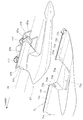
図3は本発明に係るグラブレール取付部構造を示す車体後部平面図であり、左右一対のリヤボディカバー71,72にそれぞれ切欠き71a,72aが設けられ、これらの切欠き71a,72aに左右のグラブレール67,68の内方延出部67b,68bが通され、グラブレール67,68の把持部67a,68aがシート56の側縁56a,56bに沿って延びた状態を示している。
FIG. 3 is a plan view of the rear portion of the vehicle body showing the structure of the grab rail mounting portion according to the present invention. The pair of left and right rear body covers 71 and 72 are provided with
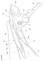
図4は本発明に係るグラブレール取付部構造を示す斜視図であり、リヤボディカバー71の切欠き71aにグラブレール67の内方延出部67bが合わせられた状態を示している。
FIG. 4 is a perspective view showing the structure of the grab rail mounting portion according to the present invention, and shows a state where the inwardly extending
内方延出部67bは、リヤボディカバー71の外観面71cに連続するように設けられた化粧面67eを備える。他のグラブレール68(図3参照)についても、リヤボディカバー72(図3参照)の外観面72c(不図示)に連続するように設けられた化粧面68e(不図示)を備える。
The inwardly extending
このように、グラブレール67,68に化粧面67e,68eを設けることで、リヤボディカバー71,72(一方の符号71のみ示す。)とグラブレール67,68との一体感を得ることができる。
Thus, by providing the
図5(a),(b)は本発明に係るグラブレールの説明図である。
(a)はグラブレール67の平面図であり、グラブレール67は、把持部67aと内方延出部67bとからなり、内方延出部67bは、リヤボディカバー71の切欠き71aに嵌合する嵌合部67fと、シートレール15(図1参照)側に取付けられるシートレール側取付部67gとからなる。
5A and 5B are explanatory views of the grab rail according to the present invention.
(A) is a plan view of the
嵌合部67fと切欠き71aとの間には、外観性及び組付け性の影響を与えない程度の小さな隙間を有する。
嵌合部67fは、化粧面67eの一部を含むとともにシートレール側取付部67gに隣接する縦壁部67hとを備える。
シートレール側取付部67gは、シートレール15側のグラブレール支持ブラケット(不図示)に取付けるためのボルト挿通穴67j,67jを備える。
There is a small gap between the
The
The seat rail
把持部67aは、内方延出部67bに連結される幅広の基部67mと、この基部67mから後方に延びる細軸部67nと、この細軸部67nの後端に設けられた車体内側へ膨出する膨出部67pとからなる。
The
(b)はグラブレール67の側面図であり、グラブレール67の把持部67aと内方延出部67bとは、それぞれの上端が側面視で一致する。これにより、グラブレール67を側方から見たときに一体感を得ることができ、外観性を向上させることができる。
把持部67aは、側面に設けられた稜線67rが直線状又は直線に近い線状に前後方向に延びている。
(B) is a side view of the
In the
把持部67aの膨出部67pは、車体内側に膨出するのに加えて、下方にも膨出するため、細軸部67を掴んだ手が膨出部67pによって把持部67pの前後に滑りにくくすることができる。
The bulging
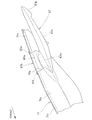
図6は本発明に係るグラブレールの取付状態及びリヤボディカバーの形状を示す斜視図であり、リヤボディカバー71の切欠き71aは、底壁71g、前壁71h及び後壁71j(符号71jについては図7参照)から形成され、前壁71hに前側切欠き部71mが形成され、後壁71jに後側切欠き部71n(図7参照)が形成されている。
FIG. 6 is a perspective view showing the mounting state of the grab rail and the shape of the rear body cover according to the present invention. The
グラブレール67は、リヤボディカバー71の切欠き71aにおける前壁71h及び後壁71jの車体内側の縁71p,71qと、リヤボディカバー71の上縁に形成された上起立壁71r,71sの内側面71t,71tとに当てるために縦壁部67hの両端に形成された側部縦壁67t,67u、並びに、これらの側部縦壁67t,67uに繋がるとともに内方延出部67bの前後端の水平又は水平に近い状態に設けられた横壁67v,67wを備える。
横壁67v,67wは、それぞれリヤボディカバー71の前側切欠き部71m、後側切欠き部71nに挿入される。
The
The
グラブレール67が支持されるグラブレール支持ブラケット115は、断面コ字形状を成す部材であり、グラブ支持ブラケット115の上部にグラブレール67が2本のボルト117,117で取付けられ、グラブレール支持ブラケット115の下部がシートレール15に取付けられている。
The grab
図7は本発明に係るグラブレール取付部構造を示す要部平面図であり、グラブレール67の内方延出部67bがリヤボディカバー71の切欠き71aに嵌合し、グラブレール67の側部縦壁67t,67uがリヤボディカバー71の内側面71t,71tに当たっている状態を示している。
FIG. 7 is a plan view of the main part showing the structure of the grab rail mounting portion according to the present invention. The inwardly extending
これにより、例えば、リヤボディカバー1に側方から外力が作用したときに、グラブレール67の側部縦壁67t,67uでリヤボディカバー71の切欠き71aの縁71p,71q及び内側面71t,71tを受けることができ、リヤボディカバー71を補強することができる。
Thereby, for example, when an external force is applied to the rear body cover 1 from the side, the
以上の図3、図6、図7に示したように、シート56を支持する左右一対のシートレール15,16(一方の符号15のみ示す。)の周囲が車体カバーとしてのリヤボディカバー71,72で覆われるとともにシートレール15,16にグラブレール67,68が取付けられ、リヤボディカバー71,72にそれぞれグラブレール67,68が通される切欠き71a,72a(一方の符号71aのみ示す。)が形成されたグラブレール取付部構造において、グラブレール67,68に、切欠き71a,72aの縁71p,71qを内側から支持する車体カバー受け部としての側部縦壁67t,67uが設けられるので、リヤボディカバー71,72に切欠き71a,72aが設けられても、側部縦壁67t,67uによって切欠き71a,72aの縁71p,71qを内側から支持することで、リヤボディカバー71,72を補強することができ、リヤボディカバー71,72に車体内方へ向かう外力が作用しても、リヤボディカバー71,72を確実に受けることができる。
As shown in FIGS. 3, 6, and 7, the periphery of the pair of left and right seat rails 15 and 16 (only one
また、グラブレール67,68が、切欠き71a,72aを塞ぐカバー部としての嵌合部67f,68f(一方の符号67fのみ示す。)を備え、この嵌合部67f,68fの表面としての化粧面67e,68e(一方の符号67eのみ示す。)がリヤボディカバー71,72の表面としての外観面71c,72c(一方の符号71cのみ示す。)に連続するように形成されているので、グラブレール67,68を握る際に嵌合部67f,68fに触れやすくなり、リヤボディカバー71,72に外力が伝わりにくくすることができる。また、リヤボディカバー71,72とグラブレール67,68との一体感を得ることができ、商品性を向上させることができる。
Further, the grab rails 67 and 68 are provided with
本発明は、二輪車に好適である。 The present invention is suitable for motorcycles.
15,16…シートレール、56…シート、67,68…グラブレール、67e,68e…カバー部の表面(化粧面)、67f,68f…カバー部(嵌合部)、67t,67u…車体カバー受け部(側部縦壁)、71,72…車体カバー(リアボディカバー)、71a,72a…切欠き、71c,72c…車体カバーの表面(外観面)、71p,71q…切欠きの縁。 15, 16 ... seat rail, 56 ... seat, 67, 68 ... grab rail, 67e, 68e ... cover surface (decorative surface), 67f, 68f ... cover portion (fitting portion), 67t, 67u ... body cover cover Portions (side vertical walls), 71, 72 ... body cover (rear body cover), 71a, 72a ... notches, 71c, 72c ... surface of vehicle body cover (appearance surface), 71p, 71q ... edges of the notches.
Claims (2)
前記グラブレールに、前記切欠きの縁を内側から支持する車体カバー受け部が設けられることを特徴とするグラブレール取付部構造。 In the grab rail mounting part structure in which the periphery of the seat rail that supports the seat is covered with a vehicle body cover, the grab rail is attached to the seat rail, and a notch through which the grab rail is passed through the vehicle body cover is formed.
The grab rail mounting part structure is characterized in that the grab rail is provided with a vehicle body cover receiving part for supporting an edge of the notch from the inside.
Priority Applications (4)
| Application Number | Priority Date | Filing Date | Title |
|---|---|---|---|
| JP2008198967A JP5225778B2 (en) | 2008-07-31 | 2008-07-31 | Grab rail mounting structure |
| BRPI0901754 BRPI0901754A2 (en) | 2008-07-31 | 2009-05-26 | frame for holding portion of the holding bracket |
| CN2009101733352A CN101659293B (en) | 2008-07-31 | 2009-07-28 | Handrail installation portion structure |
| ARP090102889 AR073464A1 (en) | 2008-07-31 | 2009-07-29 | STRUCTURE FOR A PORTION OF INCORPORATED AGARRE RAIL |
Applications Claiming Priority (1)
| Application Number | Priority Date | Filing Date | Title |
|---|---|---|---|
| JP2008198967A JP5225778B2 (en) | 2008-07-31 | 2008-07-31 | Grab rail mounting structure |
Publications (3)
| Publication Number | Publication Date |
|---|---|
| JP2010036623A true JP2010036623A (en) | 2010-02-18 |
| JP2010036623A5 JP2010036623A5 (en) | 2011-06-02 |
| JP5225778B2 JP5225778B2 (en) | 2013-07-03 |
Family
ID=41787594
Family Applications (1)
| Application Number | Title | Priority Date | Filing Date |
|---|---|---|---|
| JP2008198967A Expired - Fee Related JP5225778B2 (en) | 2008-07-31 | 2008-07-31 | Grab rail mounting structure |
Country Status (4)
| Country | Link |
|---|---|
| JP (1) | JP5225778B2 (en) |
| CN (1) | CN101659293B (en) |
| AR (1) | AR073464A1 (en) |
| BR (1) | BRPI0901754A2 (en) |
Cited By (7)
| Publication number | Priority date | Publication date | Assignee | Title |
|---|---|---|---|---|
| JP2013193629A (en) * | 2012-03-22 | 2013-09-30 | Honda Motor Co Ltd | Grab rail mounting structure of saddle riding type vehicle |
| JP2013212741A (en) * | 2012-03-30 | 2013-10-17 | Honda Motor Co Ltd | Saddle-ride type vehicle |
| JP2015048010A (en) * | 2013-09-03 | 2015-03-16 | 本田技研工業株式会社 | Saddle-riding type vehicle |
| JP2015143088A (en) * | 2013-12-26 | 2015-08-06 | 本田技研工業株式会社 | Saddle-riding type vehicle including rear grip |
| JP2016135655A (en) * | 2015-01-23 | 2016-07-28 | 本田技研工業株式会社 | Saddle riding type vehicle |
| JP2020050308A (en) * | 2018-09-28 | 2020-04-02 | 本田技研工業株式会社 | Saddle-riding type vehicle |
| DE102015217211B4 (en) | 2015-09-09 | 2022-05-05 | Bayerische Motoren Werke Aktiengesellschaft | Grab handle for a single-track vehicle |
Citations (6)
| Publication number | Priority date | Publication date | Assignee | Title |
|---|---|---|---|---|
| JPH06316282A (en) * | 1993-05-07 | 1994-11-15 | Honda Motor Co Ltd | Rear grip unit of motorcycle |
| JPH08324472A (en) * | 1995-06-05 | 1996-12-10 | Suzuki Motor Corp | Grip handle structure for pillion rider of motorcycle |
| JPH10203446A (en) * | 1997-01-21 | 1998-08-04 | Honda Motor Co Ltd | Mounting structure of rear grip for motorcycle |
| JP2001010567A (en) * | 1999-06-25 | 2001-01-16 | Yamaha Motor Co Ltd | Rear seat arrangement structure of motorcycle |
| JP2003306180A (en) * | 2002-04-11 | 2003-10-28 | Honda Motor Co Ltd | Mounting structure of seat lock device and grab rail of motorcycle |
| JP2004182108A (en) * | 2002-12-04 | 2004-07-02 | Honda Motor Co Ltd | Bodywork of motorcycle |
-
2008
- 2008-07-31 JP JP2008198967A patent/JP5225778B2/en not_active Expired - Fee Related
-
2009
- 2009-05-26 BR BRPI0901754 patent/BRPI0901754A2/en not_active IP Right Cessation
- 2009-07-28 CN CN2009101733352A patent/CN101659293B/en active Active
- 2009-07-29 AR ARP090102889 patent/AR073464A1/en active IP Right Grant
Patent Citations (6)
| Publication number | Priority date | Publication date | Assignee | Title |
|---|---|---|---|---|
| JPH06316282A (en) * | 1993-05-07 | 1994-11-15 | Honda Motor Co Ltd | Rear grip unit of motorcycle |
| JPH08324472A (en) * | 1995-06-05 | 1996-12-10 | Suzuki Motor Corp | Grip handle structure for pillion rider of motorcycle |
| JPH10203446A (en) * | 1997-01-21 | 1998-08-04 | Honda Motor Co Ltd | Mounting structure of rear grip for motorcycle |
| JP2001010567A (en) * | 1999-06-25 | 2001-01-16 | Yamaha Motor Co Ltd | Rear seat arrangement structure of motorcycle |
| JP2003306180A (en) * | 2002-04-11 | 2003-10-28 | Honda Motor Co Ltd | Mounting structure of seat lock device and grab rail of motorcycle |
| JP2004182108A (en) * | 2002-12-04 | 2004-07-02 | Honda Motor Co Ltd | Bodywork of motorcycle |
Cited By (8)
| Publication number | Priority date | Publication date | Assignee | Title |
|---|---|---|---|---|
| JP2013193629A (en) * | 2012-03-22 | 2013-09-30 | Honda Motor Co Ltd | Grab rail mounting structure of saddle riding type vehicle |
| JP2013212741A (en) * | 2012-03-30 | 2013-10-17 | Honda Motor Co Ltd | Saddle-ride type vehicle |
| JP2015048010A (en) * | 2013-09-03 | 2015-03-16 | 本田技研工業株式会社 | Saddle-riding type vehicle |
| JP2015143088A (en) * | 2013-12-26 | 2015-08-06 | 本田技研工業株式会社 | Saddle-riding type vehicle including rear grip |
| JP2016135655A (en) * | 2015-01-23 | 2016-07-28 | 本田技研工業株式会社 | Saddle riding type vehicle |
| TWI642584B (en) * | 2015-01-23 | 2018-12-01 | 本田技研工業股份有限公司 | Saddle-ride-type vehicle |
| DE102015217211B4 (en) | 2015-09-09 | 2022-05-05 | Bayerische Motoren Werke Aktiengesellschaft | Grab handle for a single-track vehicle |
| JP2020050308A (en) * | 2018-09-28 | 2020-04-02 | 本田技研工業株式会社 | Saddle-riding type vehicle |
Also Published As
| Publication number | Publication date |
|---|---|
| CN101659293A (en) | 2010-03-03 |
| JP5225778B2 (en) | 2013-07-03 |
| BRPI0901754A2 (en) | 2010-04-13 |
| AR073464A1 (en) | 2010-11-10 |
| CN101659293B (en) | 2012-07-04 |
Similar Documents
| Publication | Publication Date | Title |
|---|---|---|
| JP5225778B2 (en) | Grab rail mounting structure | |
| JP5332666B2 (en) | Motorcycle rear fender structure and motorcycle | |
| JP2012232622A (en) | Fuel tank for saddle riding type vehicle | |
| AU2013219250B2 (en) | Straddle type vehicle | |
| JP6045903B2 (en) | Motorcycle | |
| EP2631164B1 (en) | Saddle-riding vehicle | |
| JP5460511B2 (en) | Rear fender for vehicles | |
| JP2010247816A (en) | Motorcycle | |
| JP2010274852A (en) | Vehicle body frame structure of motorcycle | |
| JP2010036596A (en) | Theft prevention structure | |
| JP6208734B2 (en) | Saddle riding | |
| JP6132627B2 (en) | Gripping part structure of saddle riding type vehicle | |
| JP6126936B2 (en) | Battery arrangement structure for saddle riding type vehicle | |
| JP4394776B2 (en) | Seat lock structure for motorcycles | |
| JP4479454B2 (en) | Anti-theft mounting structure for motorcycles | |
| JP4788829B2 (en) | Motorcycle with an article storage room | |
| JP2008062813A (en) | Riding type vehicle | |
| JP6554494B2 (en) | Muffler support structure for motorcycles | |
| JP2010155578A (en) | Cover device of motorcycle | |
| JP2002193161A (en) | Rear carrier for motorcycle | |
| JP2010173579A (en) | Vehicle body frame structure of motorcycle and motorcycle | |
| JP6218956B2 (en) | Frame structure of saddle-ride type vehicle | |
| JP6218957B2 (en) | Frame structure of saddle-ride type vehicle | |
| JP2023030244A (en) | Saddle-riding type vehicle | |
| JP2023030245A (en) | straddle-type vehicle |
Legal Events
| Date | Code | Title | Description |
|---|---|---|---|
| A521 | Written amendment |
Free format text: JAPANESE INTERMEDIATE CODE: A523 Effective date: 20110415 |
|
| A621 | Written request for application examination |
Free format text: JAPANESE INTERMEDIATE CODE: A621 Effective date: 20110415 |
|
| A977 | Report on retrieval |
Free format text: JAPANESE INTERMEDIATE CODE: A971007 Effective date: 20120928 |
|
| A131 | Notification of reasons for refusal |
Free format text: JAPANESE INTERMEDIATE CODE: A131 Effective date: 20121030 |
|
| A521 | Written amendment |
Free format text: JAPANESE INTERMEDIATE CODE: A523 Effective date: 20121227 |
|
| TRDD | Decision of grant or rejection written | ||
| A01 | Written decision to grant a patent or to grant a registration (utility model) |
Free format text: JAPANESE INTERMEDIATE CODE: A01 Effective date: 20130305 |
|
| A61 | First payment of annual fees (during grant procedure) |
Free format text: JAPANESE INTERMEDIATE CODE: A61 Effective date: 20130313 |
|
| R150 | Certificate of patent or registration of utility model |
Ref document number: 5225778 Country of ref document: JP Free format text: JAPANESE INTERMEDIATE CODE: R150 Free format text: JAPANESE INTERMEDIATE CODE: R150 |
|
| FPAY | Renewal fee payment (event date is renewal date of database) |
Free format text: PAYMENT UNTIL: 20160322 Year of fee payment: 3 |
|
| LAPS | Cancellation because of no payment of annual fees |