JP2010035918A - Locking device of pachinko machine - Google Patents
Locking device of pachinko machine Download PDFInfo
- Publication number
- JP2010035918A JP2010035918A JP2008204359A JP2008204359A JP2010035918A JP 2010035918 A JP2010035918 A JP 2010035918A JP 2008204359 A JP2008204359 A JP 2008204359A JP 2008204359 A JP2008204359 A JP 2008204359A JP 2010035918 A JP2010035918 A JP 2010035918A
- Authority
- JP
- Japan
- Prior art keywords
- frame
- locking
- locking device
- locking rod
- base frame
- Prior art date
- Legal status (The legal status is an assumption and is not a legal conclusion. Google has not performed a legal analysis and makes no representation as to the accuracy of the status listed.)
- Granted
Links
Images


Abstract
Description
本発明は、パチンコ機の中枠に、中枠の縦枠と基枠体を兼用して取り付けられ、中枠を本体枠に対し施錠するパチンコ機の施錠装置に関する。 The present invention relates to a locking device for a pachinko machine that is attached to a middle frame of a pachinko machine using both a vertical frame and a base frame of the middle frame and locks the middle frame to a main body frame.
パチンコ機の中枠(前面枠)は、本体枠の前面に、ヒンジを介して開閉可能に装着され、さらに中枠の前面にガラス枠が開閉可能に装着される。中枠は、通常、合板などの木材を使用して形成されているが、近年、金属枠により長方形の枠状に形成されたものも知られている。 The middle frame (front frame) of the pachinko machine is mounted on the front surface of the main body frame so as to be opened and closed via a hinge, and further, the glass frame is mounted on the front surface of the middle frame so as to be opened and closed. The middle frame is usually formed using wood such as plywood, but in recent years, one formed by a metal frame in a rectangular frame shape is also known.
この種の金属枠で形成される中枠は、長方形の各辺部つまり上辺部、下辺部、左右辺部が、各々枠体として形成され、各枠体の両端部が角部で直角に突き合わせ連結固定されて、長方形の枠状に形成される。 In this type of metal frame, each side of the rectangle, that is, the upper side, the lower side, and the left and right sides are each formed as a frame, and both ends of each frame are abutted at right angles at the corners. They are connected and fixed to form a rectangular frame.
一方、この中枠を本体枠に対し施錠する場合、その施錠装置は中枠の自由端側(反ヒンジ側)の内側端部に、縦に固定され、本体枠の内側に受け金具が設けられるところ、従来、この種の施錠装置として、中枠の自由端側の右側枠部と施錠装置の基枠体とが兼用され、中枠の右側枠部となる基枠体に、シリンダ錠、中枠施錠杆、ガラス枠施錠杆を取り付けた構造の施錠装置が、下記特許文献1により提案されている。
この種の従来の施錠装置は、中枠の自由端側の右側枠部と施錠装置の基枠体とを兼用することにより、完全に別個に形成された施錠装置を中枠の内側に取り付けた場合より、中枠内のスペースを広くして、中枠内における遊技盤や各種電気機器などの収納スペースを広く確保できるようにしたものであるところ、中枠施錠杆及びガラス枠施錠杆には、鉤部が一体に形成され、中枠またはガラス枠の閉鎖時、中枠施錠杆またはガラス枠施錠杆が摺動しながら、その鉤部が本体枠側の受け金具に係止されて施錠される。 In this type of conventional locking device, the locking device formed completely separately is attached to the inside of the middle frame by combining the right frame on the free end side of the middle frame and the base frame of the locking device. In some cases, the space in the inner frame is widened to secure a large storage space for game boards and various electrical devices in the inner frame. The collar part is formed integrally, and when the middle frame or glass frame is closed, the middle frame locking collar or glass frame locking collar is slid while the collar part is locked by the receiving bracket on the main body frame side and locked. The
しかし、この中枠施錠杆及びガラス枠施錠杆は、右側枠部となる基枠体の外側面に露出して取り付けられている。また、パチンコ機の中枠は、正面視で左側の左側枠部がヒンジを介して本体枠に取り付けられ、中枠の自由端側は右側枠部の外側面となっている。 However, the middle frame locking rod and the glass frame locking rod are exposed and attached to the outer side surface of the base frame body which is the right frame portion. Moreover, the left frame of the left side of the middle frame of the pachinko machine is attached to the main body frame via a hinge when viewed from the front, and the free end side of the middle frame is the outer surface of the right frame.
さらに、中枠は本体枠に対し開閉可能に装着されるため、その自由端側の右側枠部の外側面と本体枠との間に、僅かであるが、隙間が必然的に生じる。この本体枠と中枠の右側枠部間の隙間は、この種の枠部基枠体形の施錠装置における基枠体の外側面に配設された中枠施錠杆及びガラス枠施錠杆に近く、その間に何ら障壁や壁部は設けられない。 Further, since the middle frame is attached to the main body frame so as to be openable and closable, a slight gap is inevitably generated between the outer surface of the right side frame portion on the free end side and the main body frame. The gap between the main body frame and the right side frame portion of the middle frame is close to the middle frame locking rod and the glass frame locking rod disposed on the outer surface of the base frame body in this type of frame portion base frame type locking device, There are no barriers or walls in between.
このため、不正解錠を目的として、針金などの不正器具を、本体枠と中枠の自由端側の右側枠部間の隙間に差し込んだ場合、不正器具が容易に中枠施錠杆やガラス枠施錠杆に到達し、不正な解錠行為が行なわれる可能性があった。 For this reason, when an unauthorized device such as a wire is inserted into the gap between the main body frame and the right side frame on the free end side of the middle frame for the purpose of unauthorized unlocking, the unauthorized device can be easily There was a possibility that an unlocking act would be carried out by reaching the lock cage.
本発明は、上記の課題を解決するために、中枠の縦枠と施錠装置の基枠体とが兼用される施錠装置において、針金などの不正器具による不正解錠を防止することができるパチンコ機の施錠装置を提供することを目的とする。 In order to solve the above-described problems, the present invention provides a locking device in which a vertical frame of a middle frame and a base frame body of a locking device are used together, and can be prevented from being illegally unlocked by an unauthorized instrument such as a wire. It aims at providing the locking device of a machine.
上記の目的を達成するために、本発明の請求項1のパチンコ機の施錠装置は、パチンコ機の中枠の縦枠部分と施錠装置の基枠体とが兼用されて該中枠に取り付けられ、該基枠体にシリンダ錠が取り付けられると共に、該シリンダ錠の錠軸にカム部材が固定され、該基枠体に摺動可能に取り付けられた中枠施錠杆及びガラス枠施錠杆が該カム部材に係合可能とされ、該中枠施錠杆の鉤部が本体枠側の受け部に係止され、該ガラス枠施錠杆の鉤部がガラス枠側の係止部に係止されて施錠するパチンコ機の施錠装置において、該基枠体が、正面側から背面側に向って、平面コ字状部、平面I字状部及び平面L字状部を連設した形状に形成され、該基枠体の該平面I字状部の内側面に該中枠施錠杆及びガラス枠施錠杆が摺動可能に取り付けられたことを特徴とする。
In order to achieve the above object, the locking device of the pachinko machine according to
この発明の施錠装置によれば、例えばパチンコ機の中枠の左端にヒンジが取り付けられ、中枠の右端が自由端となる場合、中枠の右側の縦枠部分と兼用して施錠装置の基枠体が中枠の右側辺部に取り付けられて使用されるが、施錠機構の要となる中枠施錠杆及びガラス枠施錠杆が、基枠体の平面I字状部の内側面に装着され、外側に対して基枠体の平面I字状部などが壁となって覆われる。このため、施錠した状態で、本体枠と中枠の右端自由端側の隙間、或いは中枠とガラス枠の右端自由端側の隙間から、不正解錠を狙って針金などの不正器具を差し込まれたとしても、基枠体の平面I字状部などが壁となって、不正器具が施錠機構の中枠施錠杆、ガラス枠施錠杆などに到達せず、不正解錠を防止することができる。 According to the locking device of the present invention, for example, when the hinge is attached to the left end of the middle frame of the pachinko machine and the right end of the middle frame is the free end, the base of the locking device is also used as the vertical frame portion on the right side of the middle frame. The frame is used by being attached to the right side of the middle frame. The middle frame locking rod and the glass frame locking rod, which are the key to the locking mechanism, are mounted on the inner surface of the plane I-shaped portion of the base frame. The flat I-shaped part of the base frame body is covered with a wall on the outside. For this reason, in the locked state, a fraudulent instrument such as a wire is inserted through the gap between the main frame and the right free end of the middle frame or the gap between the middle frame and the right free end of the glass frame. Even if the flat I-shaped part of the base frame becomes a wall, the unauthorized device does not reach the middle frame locking rod, the glass frame locking rod, etc. of the locking mechanism, thereby preventing unauthorized unlocking. .
本発明の請求項2の施錠装置は、上記請求項1のパチンコ機の施錠装置において、上記基枠体が帯板状の金属板をプレス加工により曲折して形成されたことを特徴とする。
The locking device according to
この発明によれば、基枠体が、従来使用された中空の空間部を設けた引き抜き材の枠体ではなく、金属板をプレス加工して、平面コ字状部、平面I字状部及び平面L字状部を連設して形成されるため、充分な曲げ強度を有した基枠体を低い製造コストで製造することができ、施錠装置全体の製造コストも低減することができる。 According to the present invention, the base frame is not a drawing material frame provided with a conventionally used hollow space, but a metal plate is pressed to obtain a planar U-shaped portion, a planar I-shaped portion, and Since the flat L-shaped portion is formed continuously, a base frame body having sufficient bending strength can be manufactured at a low manufacturing cost, and the manufacturing cost of the entire locking device can be reduced.
本発明の請求項3の施錠装置は、上記請求項1のパチンコ機の施錠装置において、上記基枠体の平面I字状部と平面L字状部の連設角部近傍に、開口部が形成され、該平面I字状部の内側面に配置された上記中枠施錠杆の鉤部が該開口部から背面側に突き出すように配設されることを特徴とする。 The locking device according to a third aspect of the present invention is the locking device of the pachinko machine according to the first aspect, wherein an opening is provided in the vicinity of the connecting corner of the planar I-shaped portion and the planar L-shaped portion of the base frame body. The collar portion of the middle frame locking rod formed and disposed on the inner surface of the planar I-shaped portion is disposed so as to protrude from the opening to the back side.
この発明によれば、中枠施錠杆の施錠・解錠動作を安定して確保しつつ、基枠体の正面横幅を、従来の基枠体の横幅に比べ、縮小して薄形に形成することができる。 According to the present invention, the front lateral width of the base frame body is reduced and formed in a thin shape as compared with the lateral width of the conventional base frame body while stably securing the locking / unlocking operation of the middle frame locking rod. be able to.
本発明のパチンコ機の施錠装置によれば、中枠の縦枠と施錠装置の基枠体とが兼用される施錠装置において、基枠体の平面I字状部の内側面に、中枠施錠杆及びガラス枠施錠杆が摺動可能に取り付けられるので、基枠体の平面I字状部などが、外側から差し込まれる針金などの不正器具に対し有効な壁部として作用し、針金などによる不正解錠を防止することができる。 According to the locking device of the pachinko machine of the present invention, in the locking device in which the vertical frame of the middle frame and the base frame of the locking device are combined, the inner frame locking is provided on the inner surface of the planar I-shaped portion of the base frame. Since the scissors and the glass frame locking scissors are slidably mounted, the flat I-shaped part of the base frame acts as an effective wall part against illegal instruments such as wires inserted from the outside, and the Correct unlocking can be prevented.
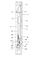
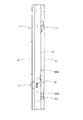
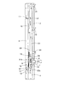
以下、本発明の実施例を図面に基づいて説明する。図1はパチンコ機用の施錠装置の正面図を、図2はその左側面図を、図3はその右側面図を、図4はその背面図を各々示している。また、図6−図8は施錠装置の分解図を示し、図9は施錠装置の取付フレームを構成する基枠体1の各面図を示している。
Embodiments of the present invention will be described below with reference to the drawings. 1 is a front view of a locking device for a pachinko machine, FIG. 2 is a left side view thereof, FIG. 3 is a right side view thereof, and FIG. 4 is a rear view thereof. 6 to 8 show exploded views of the locking device, and FIG. 9 shows each side view of the
図9に示すように、施錠装置の取付フレームを構成する基枠体1は、縦長で帯状の金属板をプレス加工により、段部を設けた平板枠状に曲折し、所定箇所に開口部などを打抜き、形成される。具体的には、図10の拡大平面図に示すように、この基枠体1は、正面側に平面コ字状部2が形成され、その平面コ字状部2の後に連続して平面I字状部3が形成され、さらにその平面I字状部3の後方背面側に連続して平面L字状部4が形成されている。
As shown in FIG. 9, the
この施錠装置の基枠体1は、中枠の右側の縦枠と兼用して使用されるもので、図10に示すように、平面コ字状部2の角部、平面L字状部4の角部及びそれらに連続する平面I字状部3との連接部が直角の角部として形成され、その幅方向にそれら5個の角部が形成されることから、長手方向に対し充分な曲げ強度を持たせている。このような基枠体1は、金属板をプレス加工により折曲・裁断・打抜き加工するのみで製作することが可能であり、従来のように、金属材料の引き抜き加工により中空部を設けて成形していた場合に比べ、低コストで製造することができる。
The
また、図10に示すように、この基枠体1は、その正面視での横幅Wの長さと奥行幅Lの長さが、約1対3.5に形成され、従来の施錠装置における基枠体に比べ、奥行幅Lに対する横幅Wの長さが短く、偏平で薄形に形成されている。図1、図4、図5に示すように、基枠体1には、内側に突き出すように、取付ブラケット6を介してシリンダ錠7が取り付けられるが、取付ブラケット6を固定する箇所はその内側の一部であり、後述の中枠施錠杆10、ガラス枠施錠杆20などは基枠体1の平面I字状部3の内側に配設されるため、装置全体としても、薄型に構成することができる。
Further, as shown in FIG. 10, the
取付ブラケット6は、図6−図8に示すように、基枠体1の平面コ字状部2の内側面から平面I字状部3の内側面にかけて取り付けられ、基枠体1の内側面に突き出すように固定される。取付ブラケット6には、シリンダ錠7を挿入するための開口孔を設けそのフランジ7bを固定する取付部を、図7に示すように、正面視で基枠体1の左側つまり内側に形成している。
As shown in FIGS. 6 to 8, the
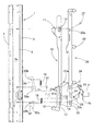
シリンダ錠7は、取付ブラケット6の取付部の背面側からその外筒部を前方に突き出すように挿入され、そのフランジ7bを取付部の背面側に当てて固定される。図6、図8に示すように、シリンダ錠7の錠軸7aにはカム部材8が固定される。カム部材8には第1係合部8aと第2係合部8bが設けられ、キーをシリンダ錠7に差し込み、右に回したとき、図4の反時計方向にカム部材8が回動し、その第1係合部8aが中枠施錠杆10の係合部13に係合し、それを下方に摺動させるようになっている。一方、キーをシリンダ錠7に差し込み、左に回したときには、図4の時計方向にカム部材8が回動し、その第2係合部8bがガラス枠施錠杆20の係合部23に係合し、それを上方に摺動させる。
The
また、基枠体1の平面L字状部4と平面I字状部3が連接する角部の上部と下部に、図9に示す如く、中枠施錠杆10の鉤部11,12を後方に突き出すための、スリット状の開口部1a、1bが形成され、さらに、同角部の中間部下寄りに、ロック解除部材31のための開口部1cが形成され、また、同角部のロック解除部材31の上方に、ロック部材30の押圧部を後方背面側に突き出すための開口部1dが形成されている。
Further, as shown in FIG. 9, the
図6に示すように、基枠体1の平面I字状部3の内側面3aに、中枠施錠杆10とガラス枠施錠杆20のガイド部が形成される。この内側面3aのガイド部は平坦に形成され、その上下方向に沿って、中枠施錠杆10とガラス枠施錠杆20が複数のガイドピンとガイド孔を介して上下摺動可能に装着される。
As shown in FIG. 6, guide portions of the middle
中枠施錠杆10は、図6−図8に示すように、帯板の上部と下部に鉤部11,12を背面側に突出して形成される。中枠施錠杆10の中間部下寄り(シリンダ錠7のカム部材8に対向した位置)に、係合部13が長孔の縁部として設けられ、上記のように、カム部材8の第1係合部8aが係合可能である。また、図6に示す如く、その係合部13の上方に、ロック解除部材31が枢軸31aにより回動可能に枢支される。このロック解除部材31は、中枠施錠杆10の施錠時に中枠施錠杆10をロックする一方、キーによるシリンダ錠7の解錠操作時にはカム部材8の回動により、そのロックを解除して中枠施錠杆10を解錠方向に摺動させるようになっている。
As shown in FIGS. 6 to 8, the middle
そのために、ロック解除部材31には、後述のロック部材30の係止部30aに係止されて中枠施錠杆10の移動をロックする係止部31bと、カム部材8の第1係合部8aに係合して、ロック解除部材31を傾動させ、ロックを解除するための、傾斜部31cが設けられている。
For this purpose, the unlocking
中枠施錠杆10には、その上部、中間部、下部にガイド孔14、15,16が形成され、それらのガイド孔14、15,16には後述のガイドピン27,28,29が挿通され、中枠施錠杆10が上下に所定の範囲内で上下摺動するようにガイドされる。また、中枠施錠杆10の下部には、後述の解錠保持部材32の係止部32aが嵌入することにより、中枠施錠杆10を解錠状態に保持するための凹状の係止部17が設けられる。
Guide holes 14, 15, 16 are formed in the upper, middle, and lower portions of the middle
解錠保持部材32は、シリンダ錠7を操作して解錠操作されたとき、中枠施錠杆10を解錠状態に保持するための部材であり、基枠体1の下部の平面I字状部3における内側面3aに、ガイドピン29によって傾動可能に枢支される。解錠保持部材32には係止部32aと押圧部32bが設けられ、シリンダ錠7を操作してカム部材8により中枠施錠杆10を下に摺動させたとき、係止部32aが中枠施錠杆10の係止部17に嵌合して、中枠施錠杆10を解錠状態に保持する。
The unlocking holding
このために、解錠保持部材32にはばね部材(コイルばね)18がガラス枠施錠杆20との間に掛け渡され、係止部32aを係止させる側に解錠保持部材32を付勢している。また、解錠保持部材32に設けられた押圧部32bは、開口部1bから背面側に突き出し可能であり、中枠41を本体枠40側に閉じたとき、受け部43の一部が押圧部32bに当たって解錠保持部材32が傾動し、これにより、その係止部32aが中枠施錠杆10の係止部17から外れ、中枠施錠杆10はばね部材19の付勢力により上昇し、施錠状態となるようになっている。
For this purpose, a spring member (coil spring) 18 is spanned between the unlocking holding
ロック部材30は、ロック解除部材31と協働して、中枠施錠杆10を施錠時にロックして針金などの不正器具による不正解錠を防止する部材であり、図6に示すように、基枠体1の下部の平面I字状部における内側面3a(解錠保持部材32の上方位置)に、ガイドピン28によって傾動可能に枢支される。ロック部材30には、その下部に突起状の係止部30aが設けられ、中枠41が閉じられて施錠状態となったとき、中枠施錠杆10に取り付けられたロック解除部材31の係止部31bに、突起状の係止部30aを係止させ、中枠施錠杆10の摺動をロックするようになっている。
The locking
ロック部材30の背面側に突設された押圧部30bは、通常時、開口部1dから基枠体1の背面側に突き出し、中枠41が閉じられて本体枠40側の一部が押圧部30bを押圧したとき、ロック部材30が図14のように、僅かに時計方向に回動し、その係止部30aを中枠施錠杆10に取り付けられたロック解除部材31の係止部31bに係止させるようになっている。
The
このロック部材30と中枠施錠杆10のロック解除部材31間には、ばね部材(コイルばね)19が掛けられ、このばね部材19によりロック部材30はその押圧部30bを背面側に突き出すように付勢され、中枠施錠杆10はロック解除部材31を介してこのばね部材19により施錠側である上方に付勢される。
A spring member (coil spring) 19 is hung between the
ガラス枠施錠杆20は、中枠施錠杆10と同様に基枠体1の平面I字状部3の内側面3aに沿って所定の範囲で上下摺動可能に装着される。ガラス枠施錠杆20は、図6に示すように、3本のガイドピン27,28,29とガイド孔20a、20b、20cを介して上下摺動可能に装着される。
The glass
ガラス枠施錠杆20には、図6−図8に示すように、帯板の上部、中間部、下部に鉤部21,22,23が背面側に突出して形成される。ガラス枠施錠杆20の中間部下寄り(シリンダ錠7のカム部材8と対向する位置)に、係合部24が長孔の縁部として設けられ、シリンダ錠7の錠軸7aを左側(図4の時計方向)に回したとき、カム部材8の第2係合部8bが係合部24に係合し、ガラス枠施錠杆20は上に持ち上げられるように上昇し、3個の鉤部21,22,23による施錠が解除されるようになっている。
As shown in FIGS. 6 to 8, the glass
ガラス枠施錠杆20と解錠保持部材32間には、ばね部材(コイルばね)18が掛けられ、このばね部材18によりガラス枠施錠杆20は下方(施錠側)に付勢されているため、解錠時には、カム部材8の回動により、ばね部材18によるばね力に抗してガラス枠施錠杆20が上方に摺動する。ガラス枠施錠杆20の下端部には、中枠を開いた状態で、手動により解錠操作するための操作レバー25が設けられている。
A spring member (coil spring) 18 is hung between the glass
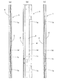
このように構成された施錠装置は、図11に示すように、基枠体1が、パチンコ機における中枠41の右端自由端側の縦枠と兼用して中枠41に取り付けられる。つまり、中枠41の右側の縦枠と兼用して中枠41に取り付けられた基枠体1は、シリンダ錠7の先端を正面側に突き出し、鉤部11,12を本体枠40側に向けた状態で装着される。一方、本体枠40の右側壁部の内側における上記鉤部11,12に対応した上下位置に、受け部43が固定され、この受け部43に鉤部11,12が係止される。
As shown in FIG. 11, in the locking device configured as described above, the
一方、中枠41の前面にガラス枠(遊技盤を覆う透明板を装着した前扉)42が開閉可能に取り付けられる。そのガラス枠42の右端自由端側の内側に、ガラス枠施錠杆20の鉤部21、22、23が係止される係止部44が、各々対応した箇所に設けられる。
On the other hand, a glass frame (a front door fitted with a transparent plate covering the game board) 42 is attached to the front surface of the
上記構成の施錠装置は、図11に示すように、パチンコ機の中枠41の右端自由端側の縦枠を兼ねて固定されて使用されるが、施錠機構の要となる中枠施錠杆10、ガラス枠施錠杆20は基枠体1の内側つまり平面I字状部3の内側面3aに装着され、外側に対して基枠体1の平面I字状部3などが壁となる。このため、施錠した状態で、本体枠40と中枠41の右端自由端側の隙間、或いは中枠41とガラス枠42の右端自由端側の隙間から、不正解錠を狙って針金などの不正器具を差し込まれたとしても、基枠体1の平面I字状部3などが壁となって、不正器具が施錠機構の要となる中枠施錠杆10、ガラス枠施錠杆20などに到達せず、不正解錠を防止することができる。
As shown in FIG. 11, the locking device having the above configuration is used while being fixed also as a vertical frame on the right end free end side of the
また、本施錠装置では、この種の施錠装置の基枠体として従来使用された中空の空間部を設けた引き抜き材のフレームではなく、帯状の金属板をプレス加工して、平面コ字状部2、平面I字状部3、平面L字状部4を形成した基枠体1を使用するため、充分な曲げ強度を有した基枠体1を低い製造コストで製造することができ、施錠装置全体の製造コストも低減することができる。
In addition, in this locking device, the flat U-shaped portion is formed by pressing a strip-shaped metal plate instead of a drawing material frame provided with a hollow space portion conventionally used as a base frame of this type of locking device. 2. Since the
さらに、施錠機構である中枠施錠杆10、ガラス枠施錠杆20などは、基枠体1の平面I字状部3の内側面3aの内側に配設され、その位置は基枠体1の後部の平面L字状部4の内側に入ることから、施錠装置全体としては、正面視で薄形に構成することができ、中枠41内の空間スペースを機器の収納用に広く使用することができる。
Further, the middle
この施錠装置は、中枠41の解錠状態において、図2、図15に示すように、中枠施錠杆10が下降位置にあり、解錠保持部材32の係止部32aが中枠施錠杆10の下部の係止部17に係止されることにより、中枠施錠杆10はその位置(解錠位置)に保持されている。このとき、ばね部材19は中枠施錠杆10を施錠方向(上方向)に付勢している。
In the unlocking state of the locking device, as shown in FIGS. 2 and 15, the middle
この状態で、パチンコ機の中枠41を本体枠40に対し閉じると、図14に示すように、本体枠40側の受け部43が施錠装置の解錠保持部材32の押圧部32bに当って、押圧部32bが相対的に押され、図14の反時計方向に解錠保持部材32が回動して、係止部32aによる係止が解除される。このとき、中枠施錠杆10はばね部材19の付勢力により上昇し、図11、図14のように鉤部11,12が本体枠40側の受け部43に係止されて施錠状態となる。
In this state, when the
同時に、図14に示すように、本体枠40側の当て部45がロック部材30の上端の押圧部30bに当たって、押圧部30bが相対的に押され、ロック部材30が図14の時計方向に回動し、これにより、ロック部材30の下端の係止部30aが、図14のようにロック解除部材31の係止部31bに係止される。これにより、中枠施錠杆10はロック部材30及びロック解除部材31を介してロックされ、シリンダ錠7による解錠操作を除き、解錠方向に摺動することができず、針金などの不正器具による不正解錠が阻止される。
At the same time, as shown in FIG. 14, the abutting
中枠41を解錠する場合、シリンダ錠7に挿入したキーを右に回す。これにより、カム部材8が図4の反時計方向に回動し、カム部材8の第1係合部8aが中枠施錠杆10の係合部13に係合して中枠施錠杆10を下方に押し下げる。このとき、中枠施錠杆10はばね部材19の付勢力に抗して下方に摺動し、その鉤部11,12が下降して、本体枠40側の受け部43から離れ、解錠される。
When unlocking the
この解錠時、解錠保持部材32は、その押圧部32bが本体枠40側の受け部43から離れるため、図15の時計方向にガイドピン29を軸に回動し、その下端の係止部32aが中枠施錠杆10の下端の係止部17に係止される。これにより、中枠施錠杆10は解錠保持部材32によって解錠位置に保持されることとなる。
At the time of unlocking, the unlocking holding
一方、ガラス枠42を中枠40に対し閉じると、ガラス枠42の内側に設けた係止部44がガラス枠施錠杆20の3箇所の鉤部21,22,23に当り、ガラス枠施錠杆20が一旦上昇した後下降して鉤部21,22,23が各係止部44に係止され、図11のように、施錠状態となる。
On the other hand, when the
ガラス枠42を解錠する場合は、図13に示すように、キーをシリンダ錠7に差し込み、左に回すと、カム部材8が図4の時計方向に回動し、カム部材8の第2係合部8bがガラス枠施錠杆20の係合部24(図6)に係合して、これを上昇させる。これにより、ガラス枠施錠杆20の各鉤部21,22,23が上昇し、ガラス枠42側の係止部44との係合が外れ、ガラス枠42が解錠状態となる。
When unlocking the
このように、ガラス枠42を中枠41に対し良好に施錠・解錠を行うことができると共に、中枠41を本体枠40に対し良好に施錠・解錠することができ、中枠41の施錠状態においては、ロック部材30とロック解除部材31の作用により、中枠施錠杆10の解錠側への摺動をロックして、針金などによる不正解錠を防止する。
As described above, the
さらに、中枠41の解錠操作時、中枠施錠杆10は解錠保持部材32により解錠位置に保持されが、中枠41を閉じると、本体枠40側の受け部43が解錠保持部材32の押圧部32bに当り、解錠保持部材32を回動させて、その係止部32aと係止部17の係止を解除させ、中枠施錠杆10をばね部材19の付勢力により上昇させて施錠状態となるので、施錠と解錠を円滑に行うことができる。
Further, when the
1 基枠体
2 平面コ字状部
3 平面I字状部
3a 内側面
4 平面L字状部
7 シリンダ錠
8 カム部材
10 中枠施錠杆
11 鉤部
13 係合部
17 係止部
18 ばね部材
19 ばね部材
20 ガラス枠施錠杆
21 鉤部
22 鉤部
23 鉤部
24 係合部
30 ロック部材
31 ロック解除部材
32 解錠保持部材
40 本体枠
41 中枠
42 ガラス枠
43 受け部
44 係止部
DESCRIPTION OF
Claims (3)
該基枠体が、正面側から背面側に向って、平面コ字状部、平面I字状部及び平面L字状部を連設した形状に形成され、該基枠体の該平面I字状部の内側面に該中枠施錠杆及びガラス枠施錠杆が摺動可能に取り付けられたことを特徴とするパチンコ機の施錠装置。 The vertical frame part of the inner frame of the pachinko machine and the base frame body of the locking device are combined and attached to the inner frame, the cylinder lock is attached to the base frame body, and the cam member is attached to the lock shaft of the cylinder lock. The middle frame locking rod and the glass frame locking rod fixed and slidably attached to the base frame body are engageable with the cam member, and the collar portion of the middle frame locking rod is a receiving portion on the main body frame side. In the locking device of the pachinko machine in which the collar part of the glass frame locking hook is locked to the locking part on the glass frame side and locked,
The base frame body is formed in a shape in which a planar U-shaped portion, a planar I-shaped portion, and a planar L-shaped portion are connected from the front side to the back side, and the planar I-shape of the base frame body A locking device for a pachinko machine, characterized in that the inner frame locking rod and the glass frame locking rod are slidably attached to the inner surface of the shaped portion.
Priority Applications (1)
| Application Number | Priority Date | Filing Date | Title |
|---|---|---|---|
| JP2008204359A JP5216469B2 (en) | 2008-08-07 | 2008-08-07 | Pachinko machine locking device |
Applications Claiming Priority (1)
| Application Number | Priority Date | Filing Date | Title |
|---|---|---|---|
| JP2008204359A JP5216469B2 (en) | 2008-08-07 | 2008-08-07 | Pachinko machine locking device |
Publications (2)
| Publication Number | Publication Date |
|---|---|
| JP2010035918A true JP2010035918A (en) | 2010-02-18 |
| JP5216469B2 JP5216469B2 (en) | 2013-06-19 |
Family
ID=42009044
Family Applications (1)
| Application Number | Title | Priority Date | Filing Date |
|---|---|---|---|
| JP2008204359A Active JP5216469B2 (en) | 2008-08-07 | 2008-08-07 | Pachinko machine locking device |
Country Status (1)
| Country | Link |
|---|---|
| JP (1) | JP5216469B2 (en) |
Citations (2)
| Publication number | Priority date | Publication date | Assignee | Title |
|---|---|---|---|---|
| JP2000317115A (en) * | 1999-05-13 | 2000-11-21 | Chuto Sangyo Kk | Bracket metal for locking device |
| JP2006230696A (en) * | 2005-02-24 | 2006-09-07 | Chuto Sangyo Kk | Locking device of game machine |
-
2008
- 2008-08-07 JP JP2008204359A patent/JP5216469B2/en active Active
Patent Citations (2)
| Publication number | Priority date | Publication date | Assignee | Title |
|---|---|---|---|---|
| JP2000317115A (en) * | 1999-05-13 | 2000-11-21 | Chuto Sangyo Kk | Bracket metal for locking device |
| JP2006230696A (en) * | 2005-02-24 | 2006-09-07 | Chuto Sangyo Kk | Locking device of game machine |
Also Published As
| Publication number | Publication date |
|---|---|
| JP5216469B2 (en) | 2013-06-19 |
Similar Documents
| Publication | Publication Date | Title |
|---|---|---|
| JP4926631B2 (en) | Locking device for gaming machines | |
| JP4926684B2 (en) | Locking device for gaming machines | |
| JP2007020922A (en) | Locking device of game machine | |
| JP5208705B2 (en) | Pachinko machine locking device | |
| JP2005199005A (en) | Locking device of game machine | |
| JP4897297B2 (en) | Locking device for gaming machine | |
| JP2007159833A (en) | Locking device for game machine | |
| JP2006218034A (en) | Locking device of game machine | |
| JP5216469B2 (en) | Pachinko machine locking device | |
| JP5052984B2 (en) | Locking device for gaming machines | |
| JP5809113B2 (en) | Game machine locking device | |
| JP4306992B2 (en) | Game machine locking device | |
| JP4741321B2 (en) | Locking device for gaming machine | |
| JPH061742Y2 (en) | Pachinko machine locking device | |
| JP5016257B2 (en) | Locking device for gaming machines | |
| JP5837479B2 (en) | Hinge for game console | |
| JPH061743Y2 (en) | Mounting structure for locking device of pachinko machine | |
| JP5095566B2 (en) | Game machine locking device | |
| JP2007252776A (en) | Locking device for game machine | |
| JP4746992B2 (en) | Game machine locking device | |
| JP4866038B2 (en) | Outer frame of pachinko machine | |
| JP5336429B2 (en) | Game machine locking device | |
| JP2000210460A (en) | Locking device for game machine | |
| JP5336446B2 (en) | Pachinko machine locking device | |
| JP4777128B2 (en) | Game machine locking device |
Legal Events
| Date | Code | Title | Description |
|---|---|---|---|
| A621 | Written request for application examination |
Free format text: JAPANESE INTERMEDIATE CODE: A621 Effective date: 20100624 |
|
| A131 | Notification of reasons for refusal |
Free format text: JAPANESE INTERMEDIATE CODE: A131 Effective date: 20120522 |
|
| A521 | Request for written amendment filed |
Free format text: JAPANESE INTERMEDIATE CODE: A523 Effective date: 20120704 |
|
| TRDD | Decision of grant or rejection written | ||
| A01 | Written decision to grant a patent or to grant a registration (utility model) |
Free format text: JAPANESE INTERMEDIATE CODE: A01 Effective date: 20130205 |
|
| A61 | First payment of annual fees (during grant procedure) |
Free format text: JAPANESE INTERMEDIATE CODE: A61 Effective date: 20130304 |
|
| R150 | Certificate of patent or registration of utility model |
Ref document number: 5216469 Country of ref document: JP Free format text: JAPANESE INTERMEDIATE CODE: R150 Free format text: JAPANESE INTERMEDIATE CODE: R150 |
|
| FPAY | Renewal fee payment (event date is renewal date of database) |
Free format text: PAYMENT UNTIL: 20160308 Year of fee payment: 3 |
|
| R250 | Receipt of annual fees |
Free format text: JAPANESE INTERMEDIATE CODE: R250 |
|
| R250 | Receipt of annual fees |
Free format text: JAPANESE INTERMEDIATE CODE: R250 |
|
| R250 | Receipt of annual fees |
Free format text: JAPANESE INTERMEDIATE CODE: R250 |