JP2010033733A - High-pressure discharge lamp electrode, high-pressure discharge lamp, and manufacturing method of high-pressure discharge lamp electrode - Google Patents
High-pressure discharge lamp electrode, high-pressure discharge lamp, and manufacturing method of high-pressure discharge lamp electrode Download PDFInfo
- Publication number
- JP2010033733A JP2010033733A JP2008191786A JP2008191786A JP2010033733A JP 2010033733 A JP2010033733 A JP 2010033733A JP 2008191786 A JP2008191786 A JP 2008191786A JP 2008191786 A JP2008191786 A JP 2008191786A JP 2010033733 A JP2010033733 A JP 2010033733A
- Authority
- JP
- Japan
- Prior art keywords
- electrode
- diameter portion
- discharge lamp
- pressure discharge
- coil
- Prior art date
- Legal status (The legal status is an assumption and is not a legal conclusion. Google has not performed a legal analysis and makes no representation as to the accuracy of the status listed.)
- Granted
Links
Images


Classifications
-
- H—ELECTRICITY
- H01—ELECTRIC ELEMENTS
- H01J—ELECTRIC DISCHARGE TUBES OR DISCHARGE LAMPS
- H01J61/00—Gas-discharge or vapour-discharge lamps
- H01J61/02—Details
- H01J61/04—Electrodes; Screens; Shields
- H01J61/06—Main electrodes
- H01J61/073—Main electrodes for high-pressure discharge lamps
- H01J61/0732—Main electrodes for high-pressure discharge lamps characterised by the construction of the electrode
-
- H—ELECTRICITY
- H01—ELECTRIC ELEMENTS
- H01J—ELECTRIC DISCHARGE TUBES OR DISCHARGE LAMPS
- H01J9/00—Apparatus or processes specially adapted for the manufacture, installation, removal, maintenance of electric discharge tubes, discharge lamps, or parts thereof; Recovery of material from discharge tubes or lamps
- H01J9/02—Manufacture of electrodes or electrode systems
- H01J9/022—Manufacture of electrodes or electrode systems of cold cathodes
- H01J9/025—Manufacture of electrodes or electrode systems of cold cathodes of field emission cathodes
Landscapes
- Engineering & Computer Science (AREA)
- Manufacturing & Machinery (AREA)
- Discharge Lamp (AREA)
Abstract
Description
本発明は高圧放電ランプの電極構造に関する。より詳しくは、プロジェクタに用いる高圧放電ランプにおける電極コイルの変形を防止するための電極構造に関する。 The present invention relates to an electrode structure of a high pressure discharge lamp. More specifically, the present invention relates to an electrode structure for preventing deformation of an electrode coil in a high-pressure discharge lamp used for a projector.
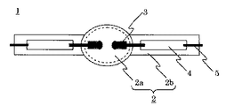
図9は一般的な超高圧水銀ランプ等の高圧放電ランプの構造を示す図である。高圧放電ランプ6は石英ガラスからなる発光管2、発光管2の発光部2aに1.5mm以下の間隔で対向配置された電極7、発光管2の封止部2bに配置されたモリブデン箔4、及びモリブデン箔4に接続された給電用のリード5を備え、発光部2aには0.15mg/mm3以上の水銀、及び10−5μmol/mm3〜10−2μmol/mm3の範囲の臭素が封入されている。
FIG. 9 is a diagram showing the structure of a high-pressure discharge lamp such as a general ultra-high pressure mercury lamp. The high-pressure discharge lamp 6 includes a
図10は図9の高圧放電ランプにおける電極7の構造を示す断面図である。電極7は電極芯棒70とそれに被覆されるコイル75からなる。図10(a)においては、電極芯棒70の先端側にコイル75が被覆され、電極芯棒70とコイル75の先端が溶融されてドーム状の先端部が形成されている。また、図10(b)においては、電極芯棒70は細径部71及び太径部72からなり、太径部72の先端側にコイル75が被覆され、太径部72とコイル75の先端が溶融されてドーム状の先端部が形成されている。
一般に、電極コイルは電極の温度を調整する機能を持ち、これによって放電状態、放電特性等が決まる。
FIG. 10 is a sectional view showing the structure of the
Generally, an electrode coil has a function of adjusting the temperature of an electrode, and this determines the discharge state, discharge characteristics, and the like.
ここで、ランプ点灯中の電極温度は2000度を超える高温になり、コイル75もその熱的な影響を受ける。図10のような構成において、コイル75は、製造当初において密に巻き付けられていたとしても、高温下でスプリングバックを起こし、モリブデン箔4の方向(図10の右側)に広がってしまう。このように電極温度を調整するためのコイル75が点灯時間とともに変形することにより電極の温度条件も変化してしまい、放電特性等が個体間でばらつくという問題があった。
Here, the electrode temperature during lighting of the lamp becomes a high temperature exceeding 2000 degrees, and the
このようなスプリングバックの問題への対処として、特許文献1には、コイルと細径部(軸棒)とを溶融により一体化する構成が開示されている。具体的には、同引例図4に開示されるように、軸棒(50)に対して先細り状にコイルを巻き付け(54)、その先細り部分を溶融することにより先端部(20)を形成するとともに、同文献の図9に開示されるように、コイルの先端側(122)だけでなく終端側(124)も軸棒(126)に溶融する構成が開示されている。
しかし、特許文献1の構成によると、確かにスプリングバック防止の効果を期待できるものの、先細り状にコイルを巻き付けるのに高度な技術を要し、さらにコイルの先端の溶融及び終端の溶融の2回の溶融工程が必要となり、生産性が悪く量産に適さないという問題があった。
また、コイルの終端位置が溶融加工の精度に依存するので終端の位置決め精度が低いという問題もあった。例えば、コイル終端の溶融工程において、コイルが溶融熱で多少延びた状態で終端が固定されてしまうことが予想される。また、加えられた熱で芯棒が再結晶化して、その部位の強度が低下することによる電極折れが危惧される。
However, according to the configuration of
In addition, since the terminal position of the coil depends on the accuracy of the melt processing, there is a problem that the terminal positioning accuracy is low. For example, in the melting process of the coil end, it is expected that the end is fixed in a state where the coil is somewhat extended by the heat of fusion. Further, there is a concern that the core rod is recrystallized by the applied heat, and the electrode breaks due to the strength of the portion being lowered.
そこで、本発明は、電極コイルのスプリングバックを防止することができ、しかも生産性が良くかつコイル終端の位置決め精度の高い高圧放電ランプ用電極を提供することを目的とする。 Accordingly, an object of the present invention is to provide an electrode for a high-pressure discharge lamp that can prevent spring back of an electrode coil, has high productivity, and has high positioning accuracy of a coil end.
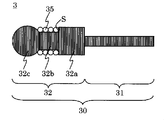
本発明の第1の側面は、電極芯棒(30)及び電極芯棒に被覆されるコイル(35)からなる高圧放電ランプ用電極であって、電極芯棒が、給電側の細径部(31)及び先端側の太径部(32)からなり、太径部が、細径部側の大径部(32a)、大径部よりも外径が小さく大径部と段差(S)を形成する小径部(32b)、及び先端部(32c)を有し、コイルが段差と先端部の間に被覆された高圧放電ランプ用電極である。 The first aspect of the present invention is a high pressure discharge lamp electrode comprising an electrode core rod (30) and a coil (35) covered with the electrode core rod, wherein the electrode core rod has a small diameter portion ( 31) and a large-diameter portion (32) on the distal end side. The large-diameter portion has a large-diameter portion (32a) on the small-diameter portion side, and has an outer diameter smaller than the large-diameter portion and a step (S). The electrode for a high-pressure discharge lamp has a small diameter portion (32b) and a tip portion (32c) to be formed, and a coil is covered between the step and the tip portion.
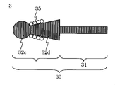
本発明の第2の側面は、電極芯棒(30)及び電極芯棒に被覆されるコイル(35)からなる高圧放電ランプ用電極であって、電極芯棒が、給電側の細径部(31)及び先端側の太径部(32)からなり、太径部が、細径部側から先端側に向けて細くなるテーパー部(32d)、及び先端部(32c)を有し、コイルがテーパー部に被覆された高圧放電ランプ用電極である。 The second aspect of the present invention is an electrode for a high-pressure discharge lamp comprising an electrode core rod (30) and a coil (35) covered with the electrode core rod, wherein the electrode core rod has a small diameter portion ( 31) and a large-diameter portion (32) on the distal end side, the large-diameter portion has a tapered portion (32d) and a distal end portion (32c) that become narrower from the small-diameter portion side toward the distal end side, and the coil is It is an electrode for a high-pressure discharge lamp covered with a tapered portion.
上記第1及び第2の側面において、小径部(32b)又はテーパー部(32d)を切削加工によって形成する構成とした。
また、太径部(32)の先端とコイル(35)の先端とが溶融されて先端部(32c)が形成される構成とした。
In the first and second side surfaces, the small diameter portion (32b) or the tapered portion (32d) is formed by cutting.
The tip of the large diameter portion (32) and the tip of the coil (35) are melted to form the tip (32c).
本発明の第3の側面は、発光管(2)、及び発光管内に対向配置された一対の上記第1又は第2の側面の高圧放電ランプ用電極(3)を備えた高圧放電ランプ(1)である。 According to a third aspect of the present invention, there is provided a high-pressure discharge lamp (1) comprising an arc tube (2) and a pair of high-pressure discharge lamp electrodes (3) of the first or second side faced in the arc tube. ).
本発明の第4の側面は、高圧放電ランプ用電極の製造方法であって、細径部及び太径部からなる電極芯棒の太径部先端側を切削加工する工程(S110、S210)、切削加工された部分にコイルを被覆する工程(S120、S220)、及び太径部の先端及びコイルの先端を溶融して先端部を形成する工程(S130、S230)からなる製造方法である。 A fourth aspect of the present invention is a method for manufacturing an electrode for a high-pressure discharge lamp, the step of cutting the distal end side of a large-diameter portion of an electrode core rod composed of a small-diameter portion and a large-diameter portion (S110, S210), This is a manufacturing method comprising a step of covering the cut portion with a coil (S120, S220) and a step of melting the tip of the large diameter portion and the tip of the coil to form the tip portion (S130, S230).
ここで、切削加工された部分が一定の外径となるようにしてもよいし、先端側に向けて細くなるテーパー形状となるようにしてもよい。 Here, the cut portion may have a constant outer diameter, or may have a tapered shape that becomes narrower toward the tip side.
上記の構成により、生産効率が高く量産に適した構成であり、かつ、確実に電極コイルのスプリングバックを防止できる。
また、溶融加工よりも高精度な位置決めが可能な切削加工によってコイル終端位置が決まるので、その終端位置に起因する個体間のばらつきをなくすことができる。
With the above configuration, the production efficiency is high and the configuration is suitable for mass production, and the spring back of the electrode coil can be reliably prevented.
In addition, since the coil end position is determined by a cutting process capable of positioning with higher accuracy than the melt process, it is possible to eliminate variations among individuals due to the end position.
図1に本発明の高圧放電ランプ1を示す。高圧放電ランプ1は、従来例の図9とは電極3の構造のみが異なり、発光管2、モリブデン箔4及びリード5やそれらの全体的な構成は図9と同様であるのでその説明を省略する。
FIG. 1 shows a high-
図2は第1の実施例の電極3の構造を示す断面図である。電極3は電極心棒30及びコイル35からなり、電極芯棒30は給電側の細径部31及び先端側の太径部32からなり、太径部32は大径部32a、小径部32b及び先端部32cからなり、コイル35は小径部32bに被覆される。これにより、大径部32aと小径部32bの段差Sによって、コイル35の細径部31方向(図の右方向)への移動が規制される。
FIG. 2 is a cross-sectional view showing the structure of the
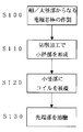
図3に図2の電極の製造方法を示す。
工程S100において、図4(a)のような細径部31及び太径部32からなる電極芯棒が作製される。
工程S110において、図4(b)のように、太径部32が切削加工されて小径部32bが形成され、大径部32aとの段差Sが形成される。
FIG. 3 shows a method for manufacturing the electrode of FIG.
In step S100, an electrode core bar made up of the
In step S110, as shown in FIG. 4B, the large-
工程S120において、図4(c)のように、コイル35が小径部32bに被覆され、段差Sによってその終端位置が決まる。
ここで、工程S120において、コイル35の小径部32bへの被覆は、予め巻きあげられた空芯状のコイル35を小径部32bに挿入して段差Sで止まるようにしてもよいし、コイル用の線材を小径部32bに巻き付けるようにしてもよい。
なお、本明細書ではコイルの装着について、上記の「挿入」の場合と「巻付け」の場合を含めて「被覆」と表現している。
In step S120, as shown in FIG. 4C, the
Here, in step S120, the small-
In this specification, the mounting of the coil is expressed as “cover” including the case of “insertion” and the case of “winding”.
工程S130において、小径部32bの先端とコイル35の先端が溶融され、図4(d)のようにドーム状の先端部32cが形成される。
上記の各工程の結果として、コイル35が段差Sと先端部32cによって挟みこまれた構成の電極が製造される。
なお、図4の各図は説明のための模擬的な図であり、各部位の寸法やコイルの巻数等は図示したものに限られない。
In step S130, the tip of the
As a result of the above steps, an electrode having a configuration in which the
Each figure in FIG. 4 is a schematic diagram for explanation, and the dimensions of each part, the number of turns of the coil, and the like are not limited to those shown in the figure.
上記のような構成により、コイル35の終端が段差Sによって固定され、スプリングバックが防止される。これにより、寿命に亘って放電の挙動を安定させることができる。
また、上記の製造方法においては、各工程はいずれも量産に適したものであり、しかも溶融工程が工程S130の1回のみで済むので、高い生産効率ないしは量産性を担保することができる。
また、コイル35の終端位置が、高精度な位置決めが可能な切削加工によって決まるので、その終端位置に起因する固体間のばらつきをなくすことができる。
With the configuration as described above, the end of the
Further, in the above manufacturing method, each step is suitable for mass production, and the melting step is only required once in step S130, so that high production efficiency or mass productivity can be ensured.
In addition, since the end position of the
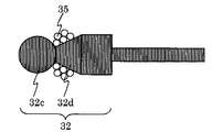
図5は第2の実施例の電極3の構造を示す断面図である。電極3は電極芯棒30及びコイル35からなり、電極芯棒30は給電側の細径部31及び先端側の太径部32からなり、太径部32はテーパー部32d及び先端部32cからなり、コイル35はテーパー部32dの先端側に被覆される。テーパー部32dによって、コイル35の細径部31方向(図の右方向)への移動が規制される。
FIG. 5 is a cross-sectional view showing the structure of the
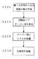
図6に図5の電極の製造方法を示す。
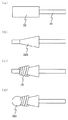
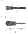
工程S200において、図7(a)のような細径部31及び太径部32からなる電極芯棒が作製・提供される。
工程S210において、図7(b)のように、太径部32に切削加工が施されてテーパー部32dが形成される。
FIG. 6 shows a method for manufacturing the electrode of FIG.
In step S200, an electrode core rod made of a
In step S210, as shown in FIG. 7B, the
工程S220において、図7(c)のように、コイル35がテーパー部32dに被覆される。
なお、工程S220において、コイル35のテーパー部32dへの被覆は、予めテーパー部32dに合わせた形状に巻きあげられた空芯状のコイル35をテーパー部32dに挿入するようにしてもよいし、コイル用の線材をテーパー部32dに巻き付けるようにしてもよい。
In step S220, as shown in FIG. 7C, the
In step S220, the
工程S230において、テーパー部32dの先端とコイル35の先端が溶融され、図7(d)に示すようにドーム状の先端部32cが形成される。
なお、図7の各図は説明のための模擬的な図であり、各部位の寸法やコイルの巻数等は図示したものに限られない。
In step S230, the tip of the tapered
Each figure in FIG. 7 is a schematic diagram for explanation, and the dimensions of each part, the number of turns of the coil, and the like are not limited to those shown in the figure.
上記のような構成により、コイル35のスプリングバックがテーパー部32dによって抑制される。これにより、寿命に亘って放電の挙動を安定させることができる。
また、上記の製造方法においては、各工程はいずれも量産に適したものであり、しかも溶融工程が工程S230の1回のみで済むので、高い生産効率ないしは量産性を担保することができる。
With the above configuration, the spring back of the
Further, in the above manufacturing method, each step is suitable for mass production, and the melting step is only required once in step S230, so that high production efficiency or mass productivity can be ensured.
<変形例>
なお、電極3の構造として、実施例1で示した段差を設ける構成と実施例2で示したテーパーを設ける構成とを適宜組み合わせて種々の変形例を構成できる。即ち、コイルの終端部の(細径部方向への)移動が太径部における段差又はテーパーによって規制されていれば本発明の目的は達成できる。
<Modification>
As the structure of the
例えば、図8Aの断面図に示すように、太径部32に大径部32a及び小径部32bを構成し、大径部32aをテーパー状にしてもよい。
また、図8Bの断面図に示すように、テーパー部32dを太径部32の一部に設けてもよい。
双方とも得られる効果は上記第1又は第2の実施例と同様である。
For example, as shown in the sectional view of FIG. 8A, a
Further, as shown in the cross-sectional view of FIG. 8B, the tapered
The effects obtained by both are the same as in the first or second embodiment.
また、図8Cの断面図に示すように、太径部に複数の大径部32a及び小径部32bを設けて各小径部にコイルを被覆してもよいし、図8Dの断面図に示すように、太径部に複数のテーパー部32dを設けて各テーパー部にコイルを被覆してもよい。これらの場合、コイルの被覆は巻付けにより行なう。これらの変形例では上記第1又は第2の実施例と同様の効果が得られるとともに、コイルを多層巻にする場合に、その巻き方に起因する層高さ方向のばらつきを抑制できる。
なお、変形例は図8A−Dに示すものに限られない。
Further, as shown in the cross-sectional view of FIG. 8C, a plurality of large-
The modification is not limited to that shown in FIGS. 8A to 8D.
1.高圧放電ランプ
2.発光管
2a.発光部
2b.封止部
3.電極
4.モリブデン箔
5.リード
30.電極芯棒
31.細径部
32.太径部
32a.大径部
32b.小径部
32c.先端部
32d.テーパー部
35.コイル
S:段差
1. 1. High pressure discharge
Claims (8)
前記電極芯棒が、給電側の細径部及び先端側の太径部からなり、
前記太径部が、前記細径部側の大径部、該大径部よりも外径が小さく該大径部と段差を形成する小径部、及び先端部を有し、前記コイルが前記段差と前記先端部の間に被覆された高圧放電ランプ用電極。 An electrode for a high-pressure discharge lamp comprising an electrode core rod and a coil coated on the electrode core rod,
The electrode core rod consists of a small diameter part on the power supply side and a large diameter part on the tip side,
The large-diameter portion has a large-diameter portion on the small-diameter portion side, a small-diameter portion whose outer diameter is smaller than the large-diameter portion and forms a step with the large-diameter portion, and a tip portion, and the coil is the step And an electrode for a high-pressure discharge lamp coated between the tip portion.
前記電極芯棒が、給電側の細径部及び先端側の太径部からなり、
前記太径部が、前記細径部側から先端側に向けて細くなるテーパー部、及び先端部を有し、前記コイルが前記テーパー部に被覆された高圧放電ランプ用電極。 An electrode for a high-pressure discharge lamp comprising an electrode core rod and a coil attached to the electrode core rod,
The electrode core rod consists of a small diameter part on the power supply side and a large diameter part on the tip side,
An electrode for a high-pressure discharge lamp, wherein the large-diameter portion has a tapered portion that narrows from the small-diameter portion side toward the distal end side, and a distal end portion, and the coil is covered with the tapered portion.
細径部及び太径部からなる電極芯棒の該太径部先端側を切削加工する工程、
前記切削加工された部分にコイルを被覆する工程、及び
前記太径部の先端及び前記コイルの先端を溶融して先端部を形成する工程
からなる製造方法。 A method for producing an electrode for a high-pressure discharge lamp, comprising:
A step of cutting the distal end side of the large-diameter portion of the electrode core rod composed of the small-diameter portion and the large-diameter portion;
A manufacturing method comprising a step of coating a coil on the cut portion, and a step of forming a tip portion by melting the tip of the large diameter portion and the tip of the coil.
Priority Applications (6)
| Application Number | Priority Date | Filing Date | Title |
|---|---|---|---|
| JP2008191786A JP5309754B2 (en) | 2008-07-25 | 2008-07-25 | High pressure discharge lamp electrode, high pressure discharge lamp, and method for manufacturing high pressure discharge lamp electrode |
| CA2731648A CA2731648C (en) | 2008-07-25 | 2009-06-09 | Electrode for high pressure discharge lamp, high pressure discharge lamp, and method for manufacturing electrode for high pressure discharge lamp |
| PCT/JP2009/060494 WO2010010759A1 (en) | 2008-07-25 | 2009-06-09 | Electrode for high-pressure discharge lamp, high-pressure discharge lamp, and method for manufacturing electrode for high-pressure discharge lamp |
| CN2009801290865A CN102105962A (en) | 2008-07-25 | 2009-06-09 | Electrode for high-pressure discharge lamp, high-pressure discharge lamp, and method for manufacturing electrode for high-pressure discharge lamp |
| EP09800275A EP2309532A4 (en) | 2008-07-25 | 2009-06-09 | Electrode for high-pressure discharge lamp, high-pressure discharge lamp, and method for manufacturing electrode for high-pressure discharge lamp |
| US13/054,872 US8159135B2 (en) | 2008-07-25 | 2009-06-09 | Electrode for high pressure discharge lamp, high pressure discharge lamp, and method for manufacturing electrode for high pressure discharge lamptechnical field |
Applications Claiming Priority (1)
| Application Number | Priority Date | Filing Date | Title |
|---|---|---|---|
| JP2008191786A JP5309754B2 (en) | 2008-07-25 | 2008-07-25 | High pressure discharge lamp electrode, high pressure discharge lamp, and method for manufacturing high pressure discharge lamp electrode |
Publications (2)
| Publication Number | Publication Date |
|---|---|
| JP2010033733A true JP2010033733A (en) | 2010-02-12 |
| JP5309754B2 JP5309754B2 (en) | 2013-10-09 |
Family
ID=41570225
Family Applications (1)
| Application Number | Title | Priority Date | Filing Date |
|---|---|---|---|
| JP2008191786A Expired - Fee Related JP5309754B2 (en) | 2008-07-25 | 2008-07-25 | High pressure discharge lamp electrode, high pressure discharge lamp, and method for manufacturing high pressure discharge lamp electrode |
Country Status (6)
| Country | Link |
|---|---|
| US (1) | US8159135B2 (en) |
| EP (1) | EP2309532A4 (en) |
| JP (1) | JP5309754B2 (en) |
| CN (1) | CN102105962A (en) |
| CA (1) | CA2731648C (en) |
| WO (1) | WO2010010759A1 (en) |
Families Citing this family (1)
| Publication number | Priority date | Publication date | Assignee | Title |
|---|---|---|---|---|
| CN106356278A (en) * | 2016-08-15 | 2017-01-25 | 广州莱拓浦电子有限公司 | Tungsten electrode and high-pressure mercury discharge lamp that uses the tungsten electrode |
Citations (9)
| Publication number | Priority date | Publication date | Assignee | Title |
|---|---|---|---|---|
| JPH02174049A (en) * | 1988-12-27 | 1990-07-05 | Ushio Inc | Discharge lamp and manufacture thereof |
| JPH03110748A (en) * | 1989-09-22 | 1991-05-10 | Stanley Electric Co Ltd | Electric discharge lamp |
| JPH0554855A (en) * | 1991-08-22 | 1993-03-05 | Toshiba Lighting & Technol Corp | Metal halide lamp |
| JPH0887977A (en) * | 1994-09-01 | 1996-04-02 | Osram Sylvania Inc | Cathode for high brightness discharge lamp and its preparation |
| JP2004362861A (en) * | 2003-06-03 | 2004-12-24 | Ushio Inc | Short-arc type extra high-pressure mercury lamp |
| JP2005166381A (en) * | 2003-12-02 | 2005-06-23 | Himeji Rika Kk | Cathode structure of gas discharge lamp |
| JP2007123150A (en) * | 2005-10-31 | 2007-05-17 | Matsushita Electric Ind Co Ltd | Electrode for discharge lamp and discharge lamp using it |
| JP2007188802A (en) * | 2006-01-16 | 2007-07-26 | Iwasaki Electric Co Ltd | High-pressure discharge lamp |
| JP2007273174A (en) * | 2006-03-30 | 2007-10-18 | Matsushita Electric Ind Co Ltd | Electrode for high-pressure discharge lamp, manufacturing method of the electrode, and process of manufacturing method of high-pressure discharge lamp |
Family Cites Families (7)
| Publication number | Priority date | Publication date | Assignee | Title |
|---|---|---|---|---|
| DE3305468A1 (en) * | 1983-02-17 | 1984-08-23 | Egyesült Izzólámpa és Villamossági Részvénytársaság, Budapest | Method for producing electrodes for high-pressure discharge lamps |
| US6705914B2 (en) * | 2000-04-18 | 2004-03-16 | Matsushita Electric Industrial Co., Ltd. | Method of forming spherical electrode surface for high intensity discharge lamp |
| US7176632B2 (en) * | 2005-03-15 | 2007-02-13 | Osram Sylvania Inc. | Slotted electrode for high intensity discharge lamp |
| JP2007095665A (en) * | 2005-09-02 | 2007-04-12 | Sony Corp | Short-arc type high-pressure discharge electrode, short-arc type high-pressure discharge tube, short-arc type high-pressure discharge light source device and their manufacturing methods |
| JP4752478B2 (en) * | 2005-12-13 | 2011-08-17 | ウシオ電機株式会社 | Light source device |
| DE112006004089A5 (en) * | 2006-12-18 | 2009-11-05 | Osram Gesellschaft mit beschränkter Haftung | Electrode for a discharge lamp |
| JP5050816B2 (en) * | 2007-11-30 | 2012-10-17 | ウシオ電機株式会社 | Super high pressure discharge lamp |
-
2008
- 2008-07-25 JP JP2008191786A patent/JP5309754B2/en not_active Expired - Fee Related
-
2009
- 2009-06-09 EP EP09800275A patent/EP2309532A4/en not_active Withdrawn
- 2009-06-09 CA CA2731648A patent/CA2731648C/en not_active Expired - Fee Related
- 2009-06-09 WO PCT/JP2009/060494 patent/WO2010010759A1/en active Application Filing
- 2009-06-09 US US13/054,872 patent/US8159135B2/en not_active Expired - Fee Related
- 2009-06-09 CN CN2009801290865A patent/CN102105962A/en active Pending
Patent Citations (9)
| Publication number | Priority date | Publication date | Assignee | Title |
|---|---|---|---|---|
| JPH02174049A (en) * | 1988-12-27 | 1990-07-05 | Ushio Inc | Discharge lamp and manufacture thereof |
| JPH03110748A (en) * | 1989-09-22 | 1991-05-10 | Stanley Electric Co Ltd | Electric discharge lamp |
| JPH0554855A (en) * | 1991-08-22 | 1993-03-05 | Toshiba Lighting & Technol Corp | Metal halide lamp |
| JPH0887977A (en) * | 1994-09-01 | 1996-04-02 | Osram Sylvania Inc | Cathode for high brightness discharge lamp and its preparation |
| JP2004362861A (en) * | 2003-06-03 | 2004-12-24 | Ushio Inc | Short-arc type extra high-pressure mercury lamp |
| JP2005166381A (en) * | 2003-12-02 | 2005-06-23 | Himeji Rika Kk | Cathode structure of gas discharge lamp |
| JP2007123150A (en) * | 2005-10-31 | 2007-05-17 | Matsushita Electric Ind Co Ltd | Electrode for discharge lamp and discharge lamp using it |
| JP2007188802A (en) * | 2006-01-16 | 2007-07-26 | Iwasaki Electric Co Ltd | High-pressure discharge lamp |
| JP2007273174A (en) * | 2006-03-30 | 2007-10-18 | Matsushita Electric Ind Co Ltd | Electrode for high-pressure discharge lamp, manufacturing method of the electrode, and process of manufacturing method of high-pressure discharge lamp |
Also Published As
| Publication number | Publication date |
|---|---|
| JP5309754B2 (en) | 2013-10-09 |
| WO2010010759A1 (en) | 2010-01-28 |
| US20110121725A1 (en) | 2011-05-26 |
| US8159135B2 (en) | 2012-04-17 |
| EP2309532A1 (en) | 2011-04-13 |
| EP2309532A4 (en) | 2011-11-16 |
| CA2731648A1 (en) | 2010-01-28 |
| CA2731648C (en) | 2013-11-12 |
| CN102105962A (en) | 2011-06-22 |
Similar Documents
| Publication | Publication Date | Title |
|---|---|---|
| JP5309754B2 (en) | High pressure discharge lamp electrode, high pressure discharge lamp, and method for manufacturing high pressure discharge lamp electrode | |
| JP4736143B2 (en) | Ultra high pressure mercury lamp electrode and ultra high pressure mercury lamp | |
| JP2012502412A (en) | Discharge lamp electrode and manufacturing method thereof | |
| JP4929961B2 (en) | High pressure mercury lamp | |
| US20100134003A1 (en) | High pressure discharge lamp | |
| JP2007273174A (en) | Electrode for high-pressure discharge lamp, manufacturing method of the electrode, and process of manufacturing method of high-pressure discharge lamp | |
| JP2014232645A (en) | Filament lamp | |
| JP7422980B2 (en) | lamp | |
| US8460045B2 (en) | High intensity discharge lamp with enhanced dimming characteristcs | |
| JP4711243B1 (en) | Electrode for high pressure discharge lamp, method for producing the same, and high pressure discharge lamp | |
| WO2011122359A1 (en) | High-pressure discharge lamp | |
| JP2007109502A (en) | Cold-cathode electrode, electrode unit, and cold-cathode fluorescent lamp | |
| US7982399B2 (en) | High-pressure gas discharge lamp having electrode rods with crack-initiating means | |
| JP6577884B2 (en) | Short arc type discharge lamp | |
| JP2006310076A (en) | Tubular incandescent lamp | |
| JP6885722B2 (en) | Short arc type discharge lamp | |
| JP6929763B2 (en) | Discharge lamp and manufacturing method of discharge lamp | |
| WO2011125386A1 (en) | Electrode for discharge lamp and manufacturing method for same | |
| US8183760B2 (en) | Coils for electron discharge devices | |
| JP5516458B2 (en) | Short arc type discharge lamp | |
| JP2009016307A (en) | Fluorescent lamp, and illuminating device with the same | |
| JP2020091941A (en) | Short arc type discharge lamp | |
| JP2010186567A (en) | Electrode for cold cathode discharge tube, and cold cathode discharge tube | |
| JP2010225420A (en) | Hot-cathode fluorescent lamp, and electrode for fluorescent lamp | |
| JP2009272124A (en) | Ultra-high-pressure mercury lamp |
Legal Events
| Date | Code | Title | Description |
|---|---|---|---|
| A621 | Written request for application examination |
Free format text: JAPANESE INTERMEDIATE CODE: A621 Effective date: 20110720 |
|
| A131 | Notification of reasons for refusal |
Free format text: JAPANESE INTERMEDIATE CODE: A131 Effective date: 20121025 |
|
| A521 | Written amendment |
Free format text: JAPANESE INTERMEDIATE CODE: A523 Effective date: 20121128 |
|
| A131 | Notification of reasons for refusal |
Free format text: JAPANESE INTERMEDIATE CODE: A131 Effective date: 20130129 |
|
| A521 | Written amendment |
Free format text: JAPANESE INTERMEDIATE CODE: A523 Effective date: 20130311 |
|
| TRDD | Decision of grant or rejection written | ||
| A01 | Written decision to grant a patent or to grant a registration (utility model) |
Free format text: JAPANESE INTERMEDIATE CODE: A01 Effective date: 20130604 |
|
| A61 | First payment of annual fees (during grant procedure) |
Free format text: JAPANESE INTERMEDIATE CODE: A61 Effective date: 20130617 |
|
| R150 | Certificate of patent or registration of utility model |
Free format text: JAPANESE INTERMEDIATE CODE: R150 |
|
| LAPS | Cancellation because of no payment of annual fees |