JP2010033403A - Computer system, virtual computer system, computer activation management method and virtual computer activation management method - Google Patents
Computer system, virtual computer system, computer activation management method and virtual computer activation management method Download PDFInfo
- Publication number
- JP2010033403A JP2010033403A JP2008195930A JP2008195930A JP2010033403A JP 2010033403 A JP2010033403 A JP 2010033403A JP 2008195930 A JP2008195930 A JP 2008195930A JP 2008195930 A JP2008195930 A JP 2008195930A JP 2010033403 A JP2010033403 A JP 2010033403A
- Authority
- JP
- Japan
- Prior art keywords
- computer
- virtual
- activation
- virtual machine
- wwn
- Prior art date
- Legal status (The legal status is an assumption and is not a legal conclusion. Google has not performed a legal analysis and makes no representation as to the accuracy of the status listed.)
- Granted
Links
Images


Classifications
-
- G—PHYSICS
- G06—COMPUTING; CALCULATING OR COUNTING
- G06F—ELECTRIC DIGITAL DATA PROCESSING
- G06F9/00—Arrangements for program control, e.g. control units
- G06F9/06—Arrangements for program control, e.g. control units using stored programs, i.e. using an internal store of processing equipment to receive or retain programs
- G06F9/44—Arrangements for executing specific programs
- G06F9/455—Emulation; Interpretation; Software simulation, e.g. virtualisation or emulation of application or operating system execution engines
-
- G—PHYSICS
- G06—COMPUTING; CALCULATING OR COUNTING
- G06F—ELECTRIC DIGITAL DATA PROCESSING
- G06F9/00—Arrangements for program control, e.g. control units
- G06F9/06—Arrangements for program control, e.g. control units using stored programs, i.e. using an internal store of processing equipment to receive or retain programs
- G06F9/44—Arrangements for executing specific programs
- G06F9/4401—Bootstrapping
-
- G—PHYSICS
- G06—COMPUTING; CALCULATING OR COUNTING
- G06F—ELECTRIC DIGITAL DATA PROCESSING
- G06F9/00—Arrangements for program control, e.g. control units
- G06F9/06—Arrangements for program control, e.g. control units using stored programs, i.e. using an internal store of processing equipment to receive or retain programs
- G06F9/46—Multiprogramming arrangements
- G06F9/50—Allocation of resources, e.g. of the central processing unit [CPU]
- G06F9/5061—Partitioning or combining of resources
- G06F9/5077—Logical partitioning of resources; Management or configuration of virtualized resources
-
- H—ELECTRICITY
- H04—ELECTRIC COMMUNICATION TECHNIQUE
- H04L—TRANSMISSION OF DIGITAL INFORMATION, e.g. TELEGRAPHIC COMMUNICATION
- H04L12/00—Data switching networks
- H04L12/02—Details
- H04L12/12—Arrangements for remote connection or disconnection of substations or of equipment thereof
-
- H—ELECTRICITY
- H04—ELECTRIC COMMUNICATION TECHNIQUE
- H04L—TRANSMISSION OF DIGITAL INFORMATION, e.g. TELEGRAPHIC COMMUNICATION
- H04L12/00—Data switching networks
- H04L12/28—Data switching networks characterised by path configuration, e.g. LAN [Local Area Networks] or WAN [Wide Area Networks]
- H04L12/40—Bus networks
- H04L12/40006—Architecture of a communication node
- H04L12/40032—Details regarding a bus interface enhancer
-
- H—ELECTRICITY
- H04—ELECTRIC COMMUNICATION TECHNIQUE
- H04L—TRANSMISSION OF DIGITAL INFORMATION, e.g. TELEGRAPHIC COMMUNICATION
- H04L12/00—Data switching networks
- H04L12/28—Data switching networks characterised by path configuration, e.g. LAN [Local Area Networks] or WAN [Wide Area Networks]
- H04L12/40—Bus networks
- H04L12/40006—Architecture of a communication node
- H04L12/40039—Details regarding the setting of the power status of a node according to activity on the bus
-
- Y—GENERAL TAGGING OF NEW TECHNOLOGICAL DEVELOPMENTS; GENERAL TAGGING OF CROSS-SECTIONAL TECHNOLOGIES SPANNING OVER SEVERAL SECTIONS OF THE IPC; TECHNICAL SUBJECTS COVERED BY FORMER USPC CROSS-REFERENCE ART COLLECTIONS [XRACs] AND DIGESTS
- Y02—TECHNOLOGIES OR APPLICATIONS FOR MITIGATION OR ADAPTATION AGAINST CLIMATE CHANGE
- Y02D—CLIMATE CHANGE MITIGATION TECHNOLOGIES IN INFORMATION AND COMMUNICATION TECHNOLOGIES [ICT], I.E. INFORMATION AND COMMUNICATION TECHNOLOGIES AIMING AT THE REDUCTION OF THEIR OWN ENERGY USE
- Y02D30/00—Reducing energy consumption in communication networks
- Y02D30/50—Reducing energy consumption in communication networks in wire-line communication networks, e.g. low power modes or reduced link rate
Abstract
Description
本発明は、計算機システムおよび仮想計算機システムの計算機起動管理方法に関し、特に、計算機の起動を抑止する技術に関する。 The present invention relates to a computer activation management method for a computer system and a virtual computer system, and more particularly to a technique for suppressing activation of a computer.
1台の計算機上に複数業務を集約する仮想化技術では、プロセッサやメモリ、入出力装置などのハードウェアリソースの利用効率を上げるとともに、処理量に応じてリソース割当を変更することが可能である。 With virtualization technology that consolidates multiple tasks on a single computer, it is possible to improve the utilization efficiency of hardware resources such as processors, memory, and input / output devices, and to change resource allocation according to the amount of processing. .
一方、複数の計算機が同一ストレージボリュームからOSを計算機に読み込み、起動するように構成することで、業務を実行する計算機を変更することが可能である。複数の計算機で共有可能なストレージ装置の構成はストレージネットワーク(SAN)と呼び、ストレージ装置と計算機はファイバチャネルスイッチやストレージスイッチを介して接続する。 On the other hand, by configuring a plurality of computers to read and start the OS from the same storage volume to the computer, it is possible to change the computer that executes the business. A configuration of a storage device that can be shared by a plurality of computers is called a storage network (SAN), and the storage device and the computer are connected via a fiber channel switch or a storage switch.
共有可能なストレージ装置では、接続された全ての計算機からストレージボリュームを参照あるいは更新することができるため、セキュリティにおける課題があった。この課題に対し、ストレージ装置は、計算機が有するファイバチャネル(FC)のI/Oアダプタであるホストバスアダプタ(HBA)内に格納されているユニークな装置識別情報であるワールドワイドネーム(WWN)を用いて、ある特定の計算機とストレージ装置内のストレージボリュームとの対応付けを行っている。 In a sharable storage device, storage volumes can be referred to or updated from all connected computers, which has a security problem. In response to this problem, the storage device uses a worldwide name (WWN), which is unique device identification information stored in a host bus adapter (HBA), which is a fiber channel (FC) I / O adapter of the computer. In this way, a specific computer is associated with a storage volume in the storage apparatus.
この対応付けの機能をホストグループと呼び、ホストグループを用いることで、ストレージボリュームへのアクセスを、そのストレージボリュームに登録されたWWNを登録しているHBAを有する計算機からのみに限定する。 This function of association is called a host group, and by using the host group, access to the storage volume is limited to only a computer having an HBA that registers the WWN registered in the storage volume.
業務を実行する計算機を複数用意するときには、ホストグループに業務を実行する計算機のWWNを、計算機を切り替えるたびに登録し直すか、あらかじめホストグループに複数計算機のWWNを登録しておく。ホストグループへ登録し直す場合には、運用に手間がかかる。 When preparing a plurality of computers that execute business, the WWN of the computer that executes the business is re-registered every time the computer is switched, or the WWNs of a plurality of computers are registered in the host group in advance. When re-registering to the host group, it takes time to operate.
また、ホストグループに複数計算機のWWNを登録しておく場合には、複数計算機から同一ストレージボリュームにアクセス可能なため、セキュリティ対策にはならない。 In addition, when the WWNs of a plurality of computers are registered in the host group, the same storage volume can be accessed from a plurality of computers, so this is not a security measure.
そこで、特開2007−164305号公報(特許文献1)には、ホストグループの設定変更を不要にして運用を簡易にする管理サーバが開示されている。これは、業務を実行する計算機が変更になったときには、WWNを変更先の計算機に引き継ぎ、あらかじめ複数の計算機に割り付け可能なWWNとストレージエリア識別情報を対応付けて管理サーバに記憶しておき、管理サーバから業務を実行する計算機にWWNとストレージエリア識別情報を送り、業務を実行する計算機はWWNを設定し、ストレージエリア識別情報が示すエリアからブートするものである。 Therefore, Japanese Patent Application Laid-Open No. 2007-164305 (Patent Document 1) discloses a management server that simplifies operation by eliminating the need to change host group settings. This is because, when the computer that executes the job is changed, the WWN is taken over by the change destination computer, and the WWN that can be allocated to a plurality of computers and storage area identification information are stored in association with each other in advance in the management server. The management server sends the WWN and storage area identification information to the computer that executes the business, and the computer that executes the business sets the WWN and boots from the area indicated by the storage area identification information.
また、このような計算機が仮想計算機の場合には、仮想化機構が仮想I/Oアダプタを定義し、そこにユニークな仮想装置識別情報を格納する。米国特許出願公開第2006/0195617号明細書(特許文献2)には、計算機のI/Oアダプタ内に複数の装置識別情報を登録できる技術を用いて、仮想計算機にユニークな仮想装置識別情報をI/Oアダプタに設定するシステムが開示されている。これにより、ストレージ装置のホストグループに登録するWWNと仮想計算機の仮想I/OアダプタのWWNを一致させることができるため、ストレージボリュームにアクセスする計算機を特定の仮想計算機に限定することができる。
従来、業務を実行する計算機を、仮想計算機から計算機へ、あるいは異なる計算機上の仮想計算機に切り替えるとき、I/Oアダプタに設定する装置識別情報を切り替え先の計算機に引き継ぐことで、ホストグループの登録変更や多重登録を回避することができるようになっていた。 Conventionally, when switching a computer that executes a job from a virtual machine to a computer, or a virtual machine on a different computer, registering the host group by taking over the device identification information set in the I / O adapter to the switching destination computer Change and multiple registration can be avoided.
ここで、例えば、管理サーバが使用できなくなった、あるいは管理サーバ以外からの操作介入があった、あるいは元々重複する装置識別情報を設定しておく運用があったことにより、複数の計算機が同じ装置識別情報を持つ可能性がある。 Here, for example, the management server cannot be used, there is an operation intervention from other than the management server, or there is an operation to set originally duplicated device identification information, so that multiple computers are the same device May have identification information.
このように、同じ装置識別情報を持つ複数の計算機が起動されると、ストレージ装置のアクセス制御機構が有効に働かず、複数の計算機から同一ストレージボリュームをアクセスできてしまうという課題がある。また、I/Oアダプタがネットワークインタフェースのとき、MACアドレスなどのネットワーク装置識別情報が同一な計算機が複数ある場合には、通信エラーが発生するという課題がある。 As described above, when a plurality of computers having the same device identification information are activated, the access control mechanism of the storage device does not work effectively, and the same storage volume can be accessed from the plurality of computers. Further, when the I / O adapter is a network interface, there is a problem that a communication error occurs when there are a plurality of computers having the same network device identification information such as a MAC address.
そこで、本発明の目的は、業務を実行する計算機を切り替えるために装置識別情報を変更可能な仮想計算機または計算機に、ユーザが意図しないタイミングで起動がかかってしまったときでも、計算機が起動しないように制御することができる計算機起動管理方法を提供することにある。 Therefore, an object of the present invention is to prevent a computer from starting even when a virtual computer or a computer whose device identification information can be changed in order to switch a computer that performs a task is started at a timing unintended by the user. It is an object of the present invention to provide a computer activation management method that can be controlled automatically.
本発明の前記ならびにその他の目的と新規な特徴は、本明細書の記述および添付図面から明らかになるであろう。 The above and other objects and novel features of the present invention will be apparent from the description of this specification and the accompanying drawings.
本願において開示される発明のうち、代表的なものの概要を簡単に説明すれば、次のとおりである。 Of the inventions disclosed in the present application, the outline of typical ones will be briefly described as follows.
すなわち、代表的なものの概要は、計算機の起動の可否設定が有効か無効かを示す情報を記憶するI/Oアダプタ装置と、計算機の電源投入指示を受付けた際、I/Oアダプタ装置に記憶された情報に基づいて、情報が無効を示す情報の場合、計算機の電源投入を停止する起動管理部とを備えたものである。 That is, the outline of a typical one is stored in the I / O adapter device that stores information indicating whether the computer activation setting is valid or invalid, and when the computer power-on instruction is accepted, In the case where the information indicates invalidity based on the obtained information, the information processing apparatus includes an activation management unit that stops the power-on of the computer.
また、仮想計算機に割り付け可能な論理I/Oアダプタ装置と装置識別情報とを対応付けて記憶する装置識別管理テーブルと、仮想計算機を起動する際、装置識別管理テーブルに基づいて、仮想計算機に割り当てた論理I/Oアダプタ装置に対応する装置識別情報を調べ、装置識別情報が起動抑止を意味する値であるとき、仮想計算機の起動を抑止する仮想計算機起動部とを有する仮想化機構を備えたものである。 In addition, a device identification management table that stores a logical I / O adapter device that can be assigned to a virtual computer and device identification information in association with each other, and an allocation to the virtual computer based on the device identification management table when the virtual computer is started The virtual machine has a virtualization mechanism having a virtual machine activation unit that inhibits activation of the virtual machine when the apparatus identification information corresponding to the logical I / O adapter apparatus is checked and the apparatus identification information is a value that means activation inhibition. Is.
本願において開示される発明のうち、代表的なものによって得られる効果を簡単に説明すれば以下のとおりである。 Among the inventions disclosed in the present application, effects obtained by typical ones will be briefly described as follows.
すなわち、代表的なものによって得られる効果は、ユーザが意図しないタイミングで仮想計算機または計算機に起動がかかってしまったときでも、計算機が起動しないように制御することができる。 In other words, the effect obtained by the representative one can be controlled so that the computer is not activated even when the virtual computer or the computer is activated at a timing not intended by the user.
以下、本発明の実施の形態を図面に基づいて詳細に説明する。なお、実施の形態を説明するための全図において、同一の部材には原則として同一の符号を付し、その繰り返しの説明は省略する。 Hereinafter, embodiments of the present invention will be described in detail with reference to the drawings. Note that components having the same function are denoted by the same reference symbols throughout the drawings for describing the embodiment, and the repetitive description thereof will be omitted.
(実施の形態1)
図1により、本発明の実施の形態1に係る計算機システムの構成について説明する。図1は本発明の実施の形態1に係る計算機システムの構成を示す構成図である。
(Embodiment 1)
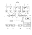
The configuration of the computer system according to
図1において、計算機システムは、複数の計算機100、ストレージシステム160、複数の計算機100とストレージシステム160を接続するストレージスイッチ140およびネットワークスイッチ150から構成されている。また、ネットワークスイッチ150には、端末190が接続され、各種設定などを行っている。
In FIG. 1, the computer system includes a plurality of
複数の計算機100は、ファイバチャネルのホストバスアダプタ(HBA)110を介してストレージスイッチ140に接続され、ネットワークインタフェースカード(NIC)120を介してネットワークスイッチ150に接続されている。
The plurality of
また、ストレージスイッチ140およびネットワークスイッチ150はストレージシステム160にもHBA161、NIC162を介して接続され、複数の計算機100からアクセスすることができるようになっている。
The
計算機100にはBMC(Baseboard Management Controller)130が内蔵されていて、ネットワークを介してハードウェアの電源制御が可能である。
The
ストレージシステム160内のディスク管理部170は、ディスクボリューム180にアクセス可能な計算機100を制限するホストグループ設定の機能を有し、計算機100に搭載のHBA110とディスクボリューム180との関係付けを行い、ホスト管理情報175として記憶する。ホスト管理情報175の設定は、端末190から行う。
The
計算機100には、ブレードシステムにおけるブレードを利用することも可能である。端末190は、そのブレードの1つを割り当ててもよい。また、複数の計算機100は、互いに離れた場所に設置されていてもよい。
The
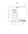
次に、図2により、本発明の実施の形態1に係る計算機システムの計算機の詳細な構成について説明する。図2は本発明の実施の形態1に係る計算機システムの計算機の詳細な構成を示す構成図である。 Next, a detailed configuration of the computer of the computer system according to the first embodiment of the present invention will be described with reference to FIG. FIG. 2 is a configuration diagram showing a detailed configuration of the computer of the computer system according to the first embodiment of the present invention.
計算機100は、計算機の状態やプログラム実行結果を表示する表示装置310、プログラムにデータを与える入力装置320、業務処理プログラムやデータを保持するメモリ330、プログラムを実行するCPU340、HBA110、NIC120、BMC130から構成されている。
The
HBA110は、ファイバチャネル通信において通信相手を特定するために必要となるWWNと呼ばれるユニークな識別子を保持している。BMC130は、主に計算機100のハードウェアの監視や制御を行う。BMC130は起動管理部135を有し、端末190からの要求に応じて計算機100の電源のON/OFFが可能である。
The HBA 110 holds a unique identifier called WWN that is necessary for specifying a communication partner in Fiber Channel communication. The BMC 130 mainly monitors and controls hardware of the
次に、図3により、本発明の実施の形態1に係る計算機システムの起動管理部の動作について説明する。図3は本発明の実施の形態1に係る計算機システムの起動管理部の動作を示すフローチャートである。
Next, the operation of the activation management unit of the computer system according to
計算機100の起動は、BMC130の起動管理部135で実行する。
The
まず、ステップ1210では、計算機100への電源投入要求を受付ける。なお、BMC135は、計算機100が起動される前に、別電源にて始動することができる。
First, in
続いて、ステップ1215では、無効WWNの定義情報を取得する。
Subsequently, in
ステップ1215で取得する無効WWNの定義情報は、例えば、起動管理部135に、外部からのコマンドや操作によりあらかじめ設定してある値か、BMC130内に記憶し、後からインタフェースを介して変更可能な値か、あるいはBSM130では保持せずに、外部の計算機からステップ1215の処理を行う際に入力する値のことである。
The invalid WWN definition information acquired in
次に、ステップ1220に進み、HBA110のWWNを読み出し、それがステップ1215で取得した無効WWNの定義情報に一致するかどうか判定する。
Next, proceeding to
ステップ1220で無効WWNが登録されていると判定すると、ステップ1230において、電源を投入して計算機100を起動することができないというエラー情報を生成する。
If it is determined in
一方、ステップ1220で無効WWNが登録されていないと判定すると、ステップ1240において計算機100に電源を入れて起動する。
On the other hand, if it is determined in
最後に、ステップ1250において、計算機の起動に成功したことを示す情報か、電源投入不可というエラー情報といった処理結果を起動操作元に出力する。
Finally, in
以上説明したように、本実施の形態では、BMC130により、計算機100の起動を要求されても起動を抑止することができる。異なる計算機100間で同一のI/Oアダプタ識別子を設定しても、少なくとも1つのHBA110へ無効WWNを登録することにより、そのHBA110を有する計算機の起動を抑止することができる。
As described above, in the present embodiment, the
以上のように、本実施の形態では、異なる計算機、または異なる計算機上のLPAR間で同一のI/Oアダプタ識別子を設定しても、少なくとも1つのHBA110へ無効WWNを登録することにより、そのHBA110を有する計算機の起動を抑止する。
As described above, in this embodiment, even if the same I / O adapter identifier is set between different computers or LPARs on different computers, the
このように処理することにより、ユーザが意図しないタイミングで計算機に起動がかかってしまったときでも、計算機が起動しないように制御することができる。 By performing processing in this way, it is possible to perform control so that the computer does not start even when the computer is started at a timing not intended by the user.
(実施の形態2)
実施の形態2は、実施の形態1の計算機100が仮想化機構を有し、仮想化機構により管理されるLPARで動作する仮想計算機システムにおいて計算機起動管理を行うものである。
(Embodiment 2)
In the second embodiment, the
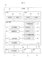
図4により、本発明の実施の形態2に係る仮想計算機システムの計算機の構成について説明する。図4は本発明の実施の形態2に係る仮想計算機システムの計算機の構成を示す構成図であり、仮想計算機システムとしての構成は、図1に示す実施の形態1の構成と同様である。
With reference to FIG. 4, the configuration of the computer of the virtual computer system according to
図4において、計算機100は、図2に示すような計算機100の構成である、HBA110、NIC120、BMC130や、図示しない表示装置310、入力装置320、メモリ330、CPU340の他に、仮想化機構220を備えており、仮想化機構220は物理的な1台の計算機を、CPU340やメモリ330を分割してLPAR(Logical Partition)200に割り当てている。このLPAR200は、仮想計算機となる。
In FIG. 4, the
これにより、1台の計算機100を論理的な複数の計算機LPAR200に見せる。LPAR200は、計算機100と同様に、仮想HBA210と仮想NIC215を有する。仮想HBA210のポートには固有のWWNが付与される。
Thereby, one
また、計算機100のHBA110は複数のポート識別情報(NポートID)をWWN管理部115に持ち、仮想HBA210のWWNをHBA110の仮想ポートに登録することができる。
Further, the
仮想化機構220はWWN管理部230、装置管理部240、LPAR管理部250、LPAR起動部260、メモリ270を有している。
The
メモリ270は、計算機識別情報235、装置識別管理テーブルであるWWN管理テーブル400、装置管理テーブル500、仮想化機構識別情報255、LPAR管理テーブル700を記憶している。仮想化機構220は、端末190から操作要求を入力し、メモリ270に記憶したデータを用いてLPAR200を操作し、操作結果を端末190に出力する。
The
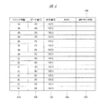
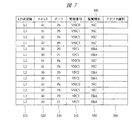
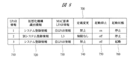
次に、図5〜図8により、本発明の実施の形態2に係る仮想計算機システムで使用されるコマンドおよびテーブルについて説明する。図5〜図8は本発明の実施の形態2に係る仮想計算機システムで使用されるコマンドおよびテーブルを示す図であり、図5はコマンドの型式を示す図、図6はWWN管理テーブルの詳細を示す図、図7は装置管理テーブルの詳細を示す図、図8はLPAR管理テーブルの詳細を示す図である。
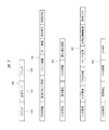
Next, commands and tables used in the virtual machine system according to the second embodiment of the present invention will be described with reference to FIGS. 5 to 8 are diagrams showing commands and tables used in the virtual machine system according to
図5において、仮想化機構220が入力するコマンド600の形式は、コマンド610、コマンドの詳細要求内容を示す要求コード620、コマンドに必要なパラメタ630からなる。パラメタ630はコマンド610と要求コード620に依存し、2つ以上連なる場合がある。
In FIG. 5, the format of the
例えば、図5に示すように、WNN登録コマンド601、LPAR管理コマンド602〜604などのコマンドがあり、無効/リセット/更新、変更属性、MAC要素、起動抑止などが、要求コード620であり、要求コード以降の情報が、パラメタ630である。
For example, as shown in FIG. 5, there are commands such as a
図6において、WWN管理テーブル400は、LPAR200に割り当て可能な仮想HBA210一覧を記憶する。
In FIG. 6, the WWN management table 400 stores a list of
カラム410は、HBA110の搭載位置を示すスロット情報を示す。計算機100がブレードのときには、スロット情報としてブレード毎のスロット搭載順序情報を用いてもよい。
A
カラム420は、HBA110が保持するポート情報を示す。カラム430は、1つのポートを複数のLPAR200で共有するための共有番号である。図6の例では、HBA110がVFC1からVFC4を保持できるので、ポート毎に4つのLPAR200から共有できることを示す。
A
カラム440は、カラム410とカラム420とカラム430とで示す仮想HBA210に与えるWWNを示している。カラム440のWWNを変更すると、そのポートを割り当てたLPAR200の仮想HBA210は変更後のWWNを使用する。カラム450は、LPAR200に仮想HBA210のポートを割り当てたとき、LPAR200のLPAR情報を記憶する。
A
図7において、装置管理テーブル500は、LPAR200に割り当てる仮想HBA210や仮想NIC215といったI/Oアダプタ装置の情報を記憶する。
In FIG. 7, the device management table 500 stores information on I / O adapter devices such as the
カラム510は、LPAR200の識別情報を示す。カラム520は、LPAR200が使用するI/Oアダプタ装置のスロット情報を示す。カラム530は、LPARが使用するI/Oアダプタ装置のポート情報を示す。
A
カラム540は、管理番号を示している。I/Oアダプタ装置が仮想NIC215の場合には、管理番号はLPAR200内でユニークなVNIC番号である。I/Oアダプタ装置が仮想HBA210の場合には、管理番号はWWN管理テーブル400で使用する共有番号である。
A
カラム550は、I/Oアダプタが仮想NIC215なのか仮想HBA210なのかを現す情報を示す。装置管理テーブル500は、装置管理部240によって、LPAR200にI/Oアダプタを割り当てるときに行を追加し、I/Oアダプタ装置の割り当てを解除するときに行を削除したり登録内容を変更することができる。カラム560は、アダプタ種別を示す。
A
仮想HBA210をLPAR200に割り当てたときには、WWN管理テーブル400のカラム450にLPAR200の識別情報を記憶する。反対に割り当てを解除したときには、カラム450が記憶する情報を削除する。
When the
LPAR200で実行する業務処理プログラムは、仮想HBA210の識別情報としてWWNを用いる。ここで用いるWWNは、WWN管理テーブル400において、LPAR200に割り当てた仮想HBA210に該当する行のカラム440を用いる。異なる計算機100の仮想化機構220がそれぞれのWWN管理テーブルのカラム440に同一のWWNを登録すると、同一WWN構成のLPAR200を構築できる。このような同一WWN構成のLPAR200間では、ストレージシステム160のホストグループの設定を変更しなくても、業務処理プログラムを再配置することができる。
The business processing program executed by the
図8において、LPAR管理テーブル700は、仮想化機構220の初期起動時に生成され、LPARを管理するために必要な定義やLPAR動作状況を記憶する。
In FIG. 8, an LPAR management table 700 is generated when the
カラム710は、LPAR200を識別する情報を示す。カラム720とカラム730は、仮想NIC215を識別するMACアドレスの生成に使用する情報を記憶する。カラム720は、計算機システムでユニークなMACアドレスを生成するために、仮想化機構識別情報255の値を用いるのか、用いないとしたらどのような値を使用するのか、といった情報を記憶する。
A
カラム730は、同じくMACアドレスを生成する要素として、仮想NIC215を用いるLPAR200の識別情報を使うのか、使わないとしたらどのような値を使用するのか、といった情報を記憶する。カラム740は、LPAR200の定義情報の変更を禁止するか否かの情報を示す。ここでLPARの定義情報とは、例えばテーブル500で管理するLPARに割り当てたI/Oアダプタ装置の情報である。
The
カラム750は、LPAR200を起動してよいか否かの情報を示す。ここで起動抑止をONにしたLPARに起動要求が入っても、仮想化機構220はそのLPARを起動しないように制御する。カラム760は、LPAR200が起動中か否かの状態を示す。
A
次に、図9により、本発明の実施の形態2に係る仮想計算機システムの計算機のWWN管理部の処理について説明する。図9は本発明の実施の形態2に係る仮想計算機システムの計算機のWWN管理部の処理を示すフローチャートであり、仮想化機構220が管理する仮想HBA210の一覧のWWNを登録する処理を示している。
Next, processing of the WWN management unit of the computer of the virtual computer system according to
まず、ステップ810では、WWN管理テーブル400更新要求を受付ける。ここで受付ける要求は、図5の601で示す形式のWWN登録コマンドである。要求コード620は、無効WWN登録を意味するコードか、WWNを初期値に戻すことを意味するコードか、WWN変更を意味するコードである。パラメタ630は、スロット番号とポート番号と共有番号とがある。WWN変更を意味する要求コードのときには、変更後のWWNの値もパラメタ630で受け取る。
First, in
続いてステップ820では、WWN管理テーブル400がメモリ270にあるか否かを調べる。ステップ820で、WWN管理テーブル400がないと判定すると、ステップ825において、WWN管理テーブル400の領域をメモリ270に確保し、HBA110の搭載数を元に、スロット情報とポート情報と共有番号の全組合せ数に相当する行を生成する。また、ステップ827において、各行のカラム440にWWN初期値を格納する。
Subsequently, in
WWN初期値とは、例えば、スロット番号とポート番号と共有番号と計算機識別情報235とを用いて生成する64ビットのユニークな値である。計算機識別情報235には、計算機100が搭載されているブレードの識別子とブレードを収めるシャーシの識別子を用いることができる。
The WWN initial value is a 64-bit unique value generated using, for example, a slot number, a port number, a shared number, and
ステップ820で、WWN管理テーブル400があると判定すると、ステップ830では、要求コード620が無効WWN設定要求を意味するコードであるか判定し、ステップ830で無効WWN設定を意味するコードであると判定すると、ステップ835では、WWN管理テーブル400の、スロット番号とポート番号と共有番号とを示すパラメタ630から特定できる行のカラム440に、無効WWN情報を格納し、ステップ880に進む。
If it is determined in
ここで無効WWN情報とは、あらかじめ仮想化機構220で定義された64ビットの情報であり、例えば16進数の2000000000000000のような値である。
Here, the invalid WWN information is 64-bit information defined in advance by the
ステップ830で判定が一致しないと判定するとステップ840に進む。ステップ840では、要求コード620がWWNを初期値に戻すリセット設定要求を意味するか判定し、ステップ840でリセット設定要求を意味すると判定すると、ステップ845にて、スロット番号とポート番号と共有番号とを示すパラメタ630の値と、計算機識別情報235とからWWN初期値を生成する。
If it is determined in
ステップ840で判定が一致しないと判定すると、ステップ850では、要求コード620がWWN更新要求を意味するコードであるか判定し、ステップ850でWWN更新要求を意味するコードであると判定すると、ステップ860に進み、ステップ850で判定が一致しないと判定すると、ステップ880に進む。
If it is determined in
ステップ860では、ステップ845で生成したWWN初期値か、あるいはパラメタ630で受け取った変更WWNが、WWN管理テーブル400の当該行以外の行に登録されているか否かを判定する。ステップ860で、重複WWNがあり、すでに登録されていると判定すると、ステップ865では、変更WWNが既存WWNと重複するというエラー情報を生成し、ステップ860で重複WWNがないと判定すると、ステップ870では、当該行のカラム440をWWN初期値か、あるいはパラメタ630で受け取った変更WWNに変更する。
In
最後にステップ880では、WWN管理テーブル400への登録に失敗したか、あるいは変更前後のWWN情報か、あるいは何も登録しなかったかといった処理結果を要求元に送る。
Finally, in
なお、ステップ870でWWNを変更する際、LPAR管理テーブル700のカラム740を調べ、定義変更禁止を登録されたLPARの仮想HBA210でないときには変更不可としてもよい。
Note that when changing the WWN in
このように、仮想化機構220では、仮想HBA210が使用するWWNを変更できる。これにより、異なる計算機100のLPAR200で使用していたWWNに変更したとき、異なる計算機100のLPAR200で使用していたディスクボリューム180を、ホスト管理情報175を変更することなくWWNを変更したLPAR200からアクセスすることができる。
Thus, the
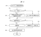
次に、図10および図11により、本発明の実施の形態2に係る仮想計算機システムの計算機のLPAR管理部の処理について説明する。図10は本発明の実施の形態2に係る仮想計算機システムの計算機のLPAR管理部の処理を示すフローチャートであり、LPAR管理部250がLPAR管理テーブル700にLPAR管理情報を登録する処理を示している。図11は本発明の実施の形態2に係る仮想計算機システムの計算機のMAC要素変更処理の詳細を示すフローチャートである。
Next, the processing of the LPAR management unit of the computer of the virtual machine system according to
まず、ステップ1010では、LPAR管理テーブル700更新要求を受付ける。ここで受付ける要求は、図6の602、603または604で示す形式のLPAR管理コマンドである。
First, in
要求コード620が定義変更属性を変更する要求のときは602の形式で、パラメタ630はLPAR情報と定義変更を禁止するか禁止を解除するかを示す値からなる。要求コード620がMAC要素を変更する要求のときは603の形式で、パラメタ630はLPAR情報とMAC要素を初期値に戻すかあるいは変更するかを示す値と、変更ならば仮想化機構情報として用いる値とMAC要素として用いるLPAR情報の値を示す値からなる。要素コード620がLPARの起動抑止の設定要求のときは604の形式で、パラメタ630はLPAR情報と起動抑止をONにするかOFFにするかを示す値からなる。
When the
続いて、ステップ1020では、要求コード620が定義変更属性登録要求を意味するコードであるか否かを判定し、ステップ1020で定義変更属性登録要求を意味するコードであると判定すると、ステップ1025において、パラメタ630のLPAR情報に対応する行のカラム740にパラメタ630の禁止あるいは禁止解除情報を格納し、ステップ1080に進む。
Subsequently, in
ステップ1020で定義変更属性登録要求を意味するコードでないと判定すると、ステップ1030では、パラメタ630のLPAR情報に対応する行のカラム740が定義変更可能であるか判定し、ステップ1030で変更禁止を示す値が格納されていると判定すると、ステップ1035では、定義変更禁止エラー情報を生成し、ステップ1080に進む。
If it is determined in
ステップ1030で定義変更が可能であると判定すると、ステップ1040に進み、要求コード620がMAC要素変更要求を意味するか否かを判定し、ステップ1040でMAC要素変更要求を意味すると判定すると、ステップ1045に進む。
If it is determined in
ここで、図11のフローチャートにより、ステップ1045の処理の詳細を説明する。
Details of the processing in
まず、ステップ1045のMACアドレス要素変更処理は、ステップ910では、パラメタ630の中にMACアドレス生成要素をリセットする意味の値があるか否かを判定し、ステップ910でMACアドレス生成要素をリセットする意味の値があると判定すると、ステップ915では、リセット後のMAC要素を仮生成する。それはLPAR管理テーブル700を初期生成するときにカラム720とカラム730に記憶する値であり、仮想化機構識別情報255の値を使うことを示す値と、パラメタ630で指定されたLPAR情報が示す値である。
First, in the MAC address element changing process in
また、ステップ910で、パラメタ630の中にMACアドレス生成要素をリセットではなく変更する意味の値があると判定すると、ステップ920に進み、パラメタ630で指定されたLPAR情報に対応するカラム720とカラム730の値を取得する。
If it is determined in
次に、ステップ930では、リセット後のMAC要素か、またはパラメタ630で渡された仮想化機構情報と要素LPARの値が、当該LPARの行以外のLPARですでに記憶している値であるか否かを判定する。
Next, in
ステップ930で、すでに登録されていると判定すると、ステップ935では、変更後のMAC要素が別のLPARと重複するというエラー情報を生成し、ステップ960に進む。
If it is determined in
また、ステップ930で登録されていないと判定するとステップ940において当該行のカラム720とカラム730を指定の値に変更し、ステップ960に進む。
If it is determined in
最後に、ステップ960では、MAC要素の登録に成功したことを示す情報かまたはエラー情報を図10のステップ1080に送る。
Finally, in
一方、ステップ1040でMAC要素変更要求でないと判定するとステップ1050に進む。ステップ1050では、要求コード620がLPAR起動抑止属性を登録する要求を意味するか否かを判定し、ステップ1050でLPAR起動抑止属性を登録する要求を意味であると判定するとステップ1060に進み、ステップ1050でLPAR起動抑止属性を登録する要求を意味でないと判定すると、ステップ1080に進む。
On the other hand, if it is determined in
ステップ1060では、パラメタ630で渡されたLPAR情報に該当する行のカラム760が起動中を示す値になっているか否かを判定する。ステップ1060で起動中を示す値になっていると判定すると、ステップ1065において、LPAR起動中による変更エラーの情報を生成する。
In
また、ステップ1060でLPARが起動中ではないと判定すると、ステップ1070に進み、カラム750にパラメタ630で渡された起動抑止属性のONかOFFを登録する。
If it is determined in
最後に、ステップ1080にて、LPAR管理テーブル700への登録に成功したことを示す情報か、またはエラー情報をコマンド要求元に出力する。
Finally, in
LPAR200で実行する業務処理プログラムは、仮想NIC215の識別情報として仮想MACアドレスを用いることがある。仮想化機構220では、仮想NIC215が使用するMACアドレスの値を生成するときに用いるMAC要素を変更できる。
A business processing program executed by the
ここで、異なる計算機100のLPAR200で使用していたMAC要素に変更すると、異なる計算機100のLPAR200と同様のネットワーク通信が可能になる。すなわち、装置管理テーブル500や業務処理プログラムの通信設定を変更することなく、業務処理プログラムをLPAR200間で再配置することができる。
Here, if the MAC element used in the
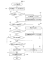
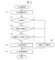
次に、図12により、本発明の実施の形態2に係る仮想計算機システムの計算機のLPAR起動部の処理について説明する。図12は本発明の実施の形態2に係る仮想計算機システムの計算機のLPAR起動部の処理を示すフローチャートである。
Next, processing of the LPAR activation unit of the computer of the virtual computer system according to
まず、ステップ1110では、LPAR起動要求を受付ける。
First, in
続いて、ステップ1120では、LPAR管理テーブル700により、起動を要求されたLPARに該当する行のカラム760が起動中を示す値になっているか否かを判定する。ステップ1120で、LPAR起動中でないと判定すると、ステップ1130に進み、ステップ1120で、LPAR起動中であると判定するとステップ1160に進む。
Subsequently, in
ステップ1130では、LPAR管理テーブル700により、起動を要求されたLPARに該当する行のカラム750が起動抑止中を示すONの値であるか否かを判定する。
In
ステップ1130で、ONでないと判定すると、ステップ1140に進み、ステップ1130で、ONであると判定すると、ステップ1160に進む。
If it is determined in
ステップ1140では、無効WWNを登録された仮想HBA210を割り当てているLPARであるか否かを判定する。この判定は、WWN管理テーブル400を用い、起動しようとしているLPARの識別子がカラム450に登録されている全ての行について、カラム440が記憶している値が無効WWNに一致するかどうかを判定する。
In
ステップ1140で、無効WWNが登録されていると判定すると、ステップ1160では、LPARを起動できないというエラー情報を生成する。
If it is determined in
一方、ステップ1140で、無効WWNが登録されていないと判定すると、ステップ1150では、LPARを起動する。このとき、LPAR管理テーブル700の該当LPARの行のカラム760に、LPAR起動中あることを示す値を登録する。さらに、装置管理テーブル500のカラム560に、I/Oアダプタ装置を識別する情報を記憶する。
On the other hand, if it is determined in
ここで、カラム550の装置種別がNICのときは、LPAR管理テーブル700のカラム720と730のMAC要素と、装置管理テーブル500のカラム540の値を組み合わせて生成したMACアドレスを識別情報として用いる。一方、カラム550の装置種別がHBAのときは、WWN管理テーブル400のカラム440に記憶しているWWNを用いる。
Here, when the device type in the
最後にステップ1170では、LPARの起動に成功したことを示す情報か、失敗したときはエラー情報といった処理結果を要求元に出力する。
Finally, in
以上のように、本実施の形態では、仮想化機構220では、起動を要求されても起動を抑止するLPARを用意することができる。異なる計算機上のLPARに同一のI/Oアダプタ識別子を設定しても、不用意なLPAR操作によるそれら複数LPARの同時起動を抑止できる。
As described above, in this embodiment, the
このように処理することにより、ユーザが意図しないタイミングで仮想計算機に起動がかかってしまったときでも、仮想計算機が起動しないように制御することができる。 By performing the processing in this way, it is possible to control the virtual machine so that it does not start even when the virtual machine is started at a timing not intended by the user.
以上、本発明者によってなされた発明を実施の形態に基づき具体的に説明したが、本発明は前記実施の形態に限定されるものではなく、その要旨を逸脱しない範囲で種々変更可能であることはいうまでもない。 As mentioned above, the invention made by the present inventor has been specifically described based on the embodiment. However, the present invention is not limited to the embodiment, and various modifications can be made without departing from the scope of the invention. Needless to say.
本発明は、計算機システムおよび仮想計算機システムの計算機起動管理方法に関し、計算機や仮想計算機の起動を抑止する制御を行うシステムなどに広く適用可能である。 The present invention relates to a computer system and a computer activation management method for a virtual computer system, and can be widely applied to a system that performs control for suppressing activation of a computer or a virtual computer.
100…計算機、110、161…HBA、115…WWN管理部、120、162…NIC、130…BMC、140…ストレージスイッチ、150…ネットワークスイッチ、160…ストレージシステム、170…ディスク管理部、180…ディスクボリューム、200…LPAR、210…仮想HBA、215…仮想NIC、220…仮想化機構、230…WWN管理部、235…計算機識別情報、240…装置管理部、250…LPAR管理部、255…仮想化機構識別情報、260…LPAR起動部、270…メモリ、400…WWN管理テーブル、500…装置管理テーブル、700…LPAR管理テーブル。
DESCRIPTION OF
Claims (7)
前記計算機は、前記ネットワークと接続するI/Oアダプタ装置と、前記計算機の電源投入を制御する起動管理部とを有し、
前記I/Oアダプタ装置は、前記計算機の起動の可否設定が有効か無効かを示す情報を記憶し、
前記起動管理部は、前記計算機の電源投入指示を受付けた際、前記I/Oアダプタ装置に記憶された情報に基づいて、前記情報が無効を示す情報の場合、前記計算機の電源投入を停止することを特徴とする計算機システム。 A computer system comprising a plurality of computers for executing a program and a storage system connected to the computers via a network,
The computer includes an I / O adapter device connected to the network, and an activation management unit that controls power-on of the computer,
The I / O adapter device stores information indicating whether the computer activation setting is valid or invalid,
When the startup management unit receives a power-on instruction for the computer, based on the information stored in the I / O adapter device, the start-up management unit stops the power-on of the computer if the information is invalid. A computer system characterized by that.
前記計算機の起動の可否設定が有効か無効かを示す情報として、前記I/Oアダプタ装置に登録された装置識別情報を用いることを特徴とする計算機システム。 The computer system according to claim 1,
A computer system characterized in that device identification information registered in the I / O adapter device is used as information indicating whether the computer activation setting is valid or invalid.
前記I/Oアダプタ装置により、前記計算機の起動の可否設定が有効か無効かを示す情報を記憶し、前記起動管理部により、前記計算機の電源投入指示を受付けた際、前記I/Oアダプタ装置に記憶された情報に基づいて、前記情報が無効を示す情報の場合、前記計算機の電源投入を停止させることを特徴とする計算機起動管理方法。 A plurality of computers for executing a program; and a storage system connected to the computer via a network. The computer controls an I / O adapter device connected to the network and power-on of the computer. A computer activation management method for a computer system having an activation management unit,
The I / O adapter device stores information indicating whether the computer activation setting is valid or invalid, and the I / O adapter device receives the computer power-on instruction from the activation management unit. A computer activation management method characterized in that, when the information is invalid, the computer is turned off based on the information stored in the computer.
前記仮想化機構は、
前記仮想計算機に割り付け可能な論理I/Oアダプタ装置と装置識別情報とを対応付けて記憶する装置識別管理テーブルと、
前記仮想計算機を起動する際、前記装置識別管理テーブルに基づいて、前記仮想計算機に割り当てた論理I/Oアダプタ装置に対応する装置識別情報を調べ、前記装置識別情報が起動抑止を意味する値であるとき、前記仮想計算機の起動を抑止する仮想計算機起動部とを有することを特徴とする仮想計算機システム。 A virtual computer system comprising a plurality of computers for executing a program and a storage system connected to the computer via a network, and generating a virtual computer on the computer by a virtualization mechanism in the computer,
The virtualization mechanism is:
A device identification management table that stores a logical I / O adapter device that can be allocated to the virtual machine and device identification information in association with each other;
When starting the virtual machine, the device identification information corresponding to the logical I / O adapter device assigned to the virtual machine is checked based on the device identification management table, and the device identification information is a value that means activation inhibition. A virtual machine system comprising: a virtual machine starting unit that suppresses starting of the virtual machine.
前記装置識別情報として、前記論理I/Oアダプタ装置に対応付けて登録されたワールドワイドネームを用いることを特徴とする仮想計算機システム。 The virtual machine system according to claim 4, wherein
A virtual computer system using a world wide name registered in association with the logical I / O adapter device as the device identification information.
前記仮想化機構により、前記仮想計算機に割り付け可能な論理I/Oアダプタ装置と装置識別情報とを対応付けて記憶し、前記仮想計算機を起動する際、前記仮想計算機に割り当てた論理I/Oアダプタ装置に対応する装置識別情報を調べ、前記装置識別情報が起動抑止を意味する値であるとき、前記仮想計算機の起動を抑止することを特徴とする仮想計算機起動管理方法。 Virtual computer activation of a virtual computer system comprising a plurality of computers for executing a program and a storage system connected to the computer via a network, and generating a virtual computer on the computer by a virtualization mechanism in the computer A management method,
A logical I / O adapter device that can be assigned to the virtual machine by the virtualization mechanism is stored in association with device identification information, and the logical I / O adapter assigned to the virtual computer when the virtual machine is started A virtual machine activation management method characterized by examining apparatus identification information corresponding to an apparatus and inhibiting activation of the virtual machine when the apparatus identification information is a value indicating activation inhibition.
前記仮想化機構は、
前記仮想計算機と前記仮想計算機の起動の可否設定が有効か無効かを示す情報とを対応付けて記憶する装置識別管理テーブルと、
前記仮想計算機を起動する際、前記装置識別管理テーブルに基づいて、前記起動の可否の設定が有効か無効かを示す情報を調べ、前記情報が無効を示す情報の場合、前記仮想計算機の起動を停止する仮想計算機起動部とを有することを特徴とする仮想計算機システム。 A virtual computer system comprising a plurality of computers for executing a program and a storage system connected to the computer via a network, and generating a virtual computer on the computer by a virtualization mechanism in the computer,
The virtualization mechanism is:
A device identification management table for storing the virtual machine and information indicating whether the virtual machine activation setting is valid or invalid;
When starting the virtual machine, based on the device identification management table, the information indicating whether the setting of whether or not to start is valid or invalid is checked. If the information is invalid, the virtual machine is activated. A virtual machine system comprising: a virtual machine starting unit that stops.
Priority Applications (5)
| Application Number | Priority Date | Filing Date | Title |
|---|---|---|---|
| JP2008195930A JP5149732B2 (en) | 2008-07-30 | 2008-07-30 | Virtual computer system |
| US12/482,496 US8271977B2 (en) | 2008-07-30 | 2009-06-11 | Computer system, virtual computer system, computer activation management method and virtual computer activation management method |
| EP09008001A EP2166449A1 (en) | 2008-07-30 | 2009-06-18 | Computer system, virtual computer system, computer activation management method and virtual computer activation management method |
| EP12155999A EP2500819A1 (en) | 2008-07-30 | 2009-06-18 | Computer system, virtual computer system, computer activation management method and virtual computer activation management method |
| US13/569,469 US8972989B2 (en) | 2008-07-30 | 2012-08-08 | Computer system having a virtualization mechanism that executes a judgment upon receiving a request for activation of a virtual computer |
Applications Claiming Priority (1)
| Application Number | Priority Date | Filing Date | Title |
|---|---|---|---|
| JP2008195930A JP5149732B2 (en) | 2008-07-30 | 2008-07-30 | Virtual computer system |
Related Child Applications (2)
| Application Number | Title | Priority Date | Filing Date |
|---|---|---|---|
| JP2012048162A Division JP5481508B2 (en) | 2012-03-05 | 2012-03-05 | Computer, virtualization mechanism, computer system, and virtual machine activation management method |
| JP2012048161A Division JP5553851B2 (en) | 2012-03-05 | 2012-03-05 | Computer, virtualization mechanism, and virtual machine activation management method |
Publications (3)
| Publication Number | Publication Date |
|---|---|
| JP2010033403A true JP2010033403A (en) | 2010-02-12 |
| JP2010033403A5 JP2010033403A5 (en) | 2010-12-02 |
| JP5149732B2 JP5149732B2 (en) | 2013-02-20 |
Family
ID=41217545
Family Applications (1)
| Application Number | Title | Priority Date | Filing Date |
|---|---|---|---|
| JP2008195930A Expired - Fee Related JP5149732B2 (en) | 2008-07-30 | 2008-07-30 | Virtual computer system |
Country Status (3)
| Country | Link |
|---|---|
| US (2) | US8271977B2 (en) |
| EP (2) | EP2166449A1 (en) |
| JP (1) | JP5149732B2 (en) |
Cited By (6)
| Publication number | Priority date | Publication date | Assignee | Title |
|---|---|---|---|---|
| JP2011186967A (en) * | 2010-03-11 | 2011-09-22 | Hitachi Ltd | Computer system, virtualization mechanism, and method for recovering failure of the computer system |
| WO2012176277A1 (en) | 2011-06-21 | 2012-12-27 | 富士通株式会社 | Information processing device, virtual machine management method and virtual machine management program |
| US8407702B2 (en) | 2009-12-02 | 2013-03-26 | Hitachi, Ltd. | Computer system for managing virtual machine migration |
| JP2013120552A (en) * | 2011-12-08 | 2013-06-17 | Hitachi Ltd | Virtual computer system, virtual computer management program, and mac address management method |
| EP2648095A2 (en) | 2012-04-05 | 2013-10-09 | Hitachi Ltd. | Control method of computer, computer and computer system |
| US9087181B2 (en) | 2010-12-16 | 2015-07-21 | Hitachi, Ltd. | Method of managing virtual computer, computer system and computer |
Families Citing this family (4)
| Publication number | Priority date | Publication date | Assignee | Title |
|---|---|---|---|---|
| US8793652B2 (en) | 2012-06-07 | 2014-07-29 | International Business Machines Corporation | Designing and cross-configuring software |
| JP5542788B2 (en) * | 2011-12-13 | 2014-07-09 | 株式会社日立製作所 | Virtual computer system and virtual computer migration control method |
| WO2015047240A1 (en) * | 2013-09-25 | 2015-04-02 | Hewlett Packard Development Company, L.P. | Baseboard management controller providing peer system identification |
| US11294847B1 (en) * | 2020-11-30 | 2022-04-05 | Dell Products L.P. | Fibre channel host onboarding system |
Citations (5)
| Publication number | Priority date | Publication date | Assignee | Title |
|---|---|---|---|---|
| JPH06250858A (en) * | 1993-02-24 | 1994-09-09 | Hitachi Ltd | Virtual machine system |
| JP2005228293A (en) * | 2004-01-15 | 2005-08-25 | Fujitsu Ltd | Information processing device and program |
| JP2007133854A (en) * | 2005-11-09 | 2007-05-31 | Hitachi Ltd | Computerized system and method for resource allocation |
| JP2007213494A (en) * | 2006-02-13 | 2007-08-23 | Ntt Docomo Inc | Update starting device and update starting control method |
| JP2008123170A (en) * | 2006-11-10 | 2008-05-29 | Hitachi Ltd | Access environment construction system and method |
Family Cites Families (22)
| Publication number | Priority date | Publication date | Assignee | Title |
|---|---|---|---|---|
| JP2902746B2 (en) | 1990-07-27 | 1999-06-07 | 富士通株式会社 | Virtual computer control method |
| JPH08305596A (en) | 1995-04-28 | 1996-11-22 | Fujitsu Ltd | Virtual machine system and its testing method |
| JPH10240547A (en) | 1997-02-27 | 1998-09-11 | Hitachi Software Eng Co Ltd | Job management method in client-server system utilizing data-base |
| JP3959159B2 (en) * | 1997-09-04 | 2007-08-15 | インターナショナル・ビジネス・マシーンズ・コーポレーション | Information processing system expansion unit, information processing system mounted on the expansion unit, and information processing system control method |
| KR100316647B1 (en) | 1998-07-30 | 2002-01-15 | 윤종용 | Power control method and apparatus therefor in computer system using wake on LAN signal |
| JP3837953B2 (en) * | 1999-03-12 | 2006-10-25 | 株式会社日立製作所 | Computer system |
| US6775790B2 (en) * | 2000-06-02 | 2004-08-10 | Hewlett-Packard Development Company, L.P. | Distributed fine-grained enhancements for distributed table driven I/O mapping |
| US20040059901A1 (en) * | 2002-09-25 | 2004-03-25 | Miller Joel P. | Removable configuration module for storage of component configuration data |
| US20050210304A1 (en) * | 2003-06-26 | 2005-09-22 | Copan Systems | Method and apparatus for power-efficient high-capacity scalable storage system |
| JP2005078607A (en) * | 2003-09-04 | 2005-03-24 | Sony Corp | Server, client, and network system |
| US20050154928A1 (en) * | 2004-01-08 | 2005-07-14 | International Business Machines Corporation | Remote power-on functionality in a partitioned environment |
| JP2005202652A (en) | 2004-01-15 | 2005-07-28 | Canon Inc | Application controller, control method for the same, and storage medium |
| US20060136704A1 (en) * | 2004-12-17 | 2006-06-22 | International Business Machines Corporation | System and method for selectively installing an operating system to be remotely booted within a storage area network |
| JP4733399B2 (en) * | 2005-01-28 | 2011-07-27 | 株式会社日立製作所 | Computer system, computer, storage device and management terminal |
| US20060195617A1 (en) * | 2005-02-25 | 2006-08-31 | International Business Machines Corporation | Method and system for native virtualization on a partially trusted adapter using adapter bus, device and function number for identification |
| JP4487920B2 (en) * | 2005-12-12 | 2010-06-23 | 株式会社日立製作所 | Boot control method, computer system and processing program therefor |
| US20080028053A1 (en) * | 2006-07-27 | 2008-01-31 | Benjamin Kelley | Method and system for a wake on LAN (WOL) computer system startup process |
| US8458695B2 (en) * | 2006-10-17 | 2013-06-04 | Manageiq, Inc. | Automatic optimization for virtual systems |
| US20080104424A1 (en) * | 2006-10-31 | 2008-05-01 | International Business Machines Corporation | Systems and Methods to Reduce Deployment Security Exposure Using WOL |
| JP5304640B2 (en) | 2007-03-27 | 2013-10-02 | 富士通株式会社 | Computer, startup method, and startup program |
| JP4744480B2 (en) * | 2007-05-30 | 2011-08-10 | 株式会社日立製作所 | Virtual computer system |
| US7945773B2 (en) * | 2007-09-18 | 2011-05-17 | International Business Machines Corporation | Failover of blade servers in a data center |
-
2008
- 2008-07-30 JP JP2008195930A patent/JP5149732B2/en not_active Expired - Fee Related
-
2009
- 2009-06-11 US US12/482,496 patent/US8271977B2/en not_active Expired - Fee Related
- 2009-06-18 EP EP09008001A patent/EP2166449A1/en not_active Withdrawn
- 2009-06-18 EP EP12155999A patent/EP2500819A1/en not_active Withdrawn
-
2012
- 2012-08-08 US US13/569,469 patent/US8972989B2/en not_active Expired - Fee Related
Patent Citations (5)
| Publication number | Priority date | Publication date | Assignee | Title |
|---|---|---|---|---|
| JPH06250858A (en) * | 1993-02-24 | 1994-09-09 | Hitachi Ltd | Virtual machine system |
| JP2005228293A (en) * | 2004-01-15 | 2005-08-25 | Fujitsu Ltd | Information processing device and program |
| JP2007133854A (en) * | 2005-11-09 | 2007-05-31 | Hitachi Ltd | Computerized system and method for resource allocation |
| JP2007213494A (en) * | 2006-02-13 | 2007-08-23 | Ntt Docomo Inc | Update starting device and update starting control method |
| JP2008123170A (en) * | 2006-11-10 | 2008-05-29 | Hitachi Ltd | Access environment construction system and method |
Cited By (9)
| Publication number | Priority date | Publication date | Assignee | Title |
|---|---|---|---|---|
| US8407702B2 (en) | 2009-12-02 | 2013-03-26 | Hitachi, Ltd. | Computer system for managing virtual machine migration |
| US8438565B2 (en) | 2009-12-02 | 2013-05-07 | Hitachi, Ltd. | Virtual machine migration managing method, computer using the method, virtualizer using the method and computer system using the method |
| JP2011186967A (en) * | 2010-03-11 | 2011-09-22 | Hitachi Ltd | Computer system, virtualization mechanism, and method for recovering failure of the computer system |
| US9087181B2 (en) | 2010-12-16 | 2015-07-21 | Hitachi, Ltd. | Method of managing virtual computer, computer system and computer |
| WO2012176277A1 (en) | 2011-06-21 | 2012-12-27 | 富士通株式会社 | Information processing device, virtual machine management method and virtual machine management program |
| JP2013120552A (en) * | 2011-12-08 | 2013-06-17 | Hitachi Ltd | Virtual computer system, virtual computer management program, and mac address management method |
| US9131031B2 (en) | 2011-12-08 | 2015-09-08 | Hitachi, Ltd. | Virtual computer system, virtual computer management program, and MAC address management method |
| EP2648095A2 (en) | 2012-04-05 | 2013-10-09 | Hitachi Ltd. | Control method of computer, computer and computer system |
| JP2013218400A (en) * | 2012-04-05 | 2013-10-24 | Hitachi Ltd | Control method for computer, computer, and computer system |
Also Published As
| Publication number | Publication date |
|---|---|
| US8972989B2 (en) | 2015-03-03 |
| US20100031257A1 (en) | 2010-02-04 |
| US20120324450A1 (en) | 2012-12-20 |
| EP2166449A1 (en) | 2010-03-24 |
| JP5149732B2 (en) | 2013-02-20 |
| EP2500819A1 (en) | 2012-09-19 |
| US8271977B2 (en) | 2012-09-18 |
Similar Documents
| Publication | Publication Date | Title |
|---|---|---|
| JP5149732B2 (en) | Virtual computer system | |
| JP4842210B2 (en) | Failover method, computer system, management server and spare server setting method | |
| JP4923990B2 (en) | Failover method and its computer system. | |
| US9081612B2 (en) | Virtual machine control method and virtual machine | |
| JP4487920B2 (en) | Boot control method, computer system and processing program therefor | |
| US9489274B2 (en) | System and method for performing efficient failover and virtual machine (VM) migration in virtual desktop infrastructure (VDI) | |
| US9912535B2 (en) | System and method of performing high availability configuration and validation of virtual desktop infrastructure (VDI) | |
| US20150293776A1 (en) | Data processing systems | |
| JP6458146B2 (en) | Computer and memory area management method | |
| JP5667552B2 (en) | Virtual machine system, virtual machine management program, and MAC address management method | |
| JP2011100431A (en) | Device and method for controlling virtual machine | |
| US8473709B2 (en) | Virtual volume allocating unit and method which allocate a new virtual volume to adequately-sized unused volume areas | |
| JP4817115B2 (en) | Computer system, parallel initialization method, and boot program | |
| US10642639B2 (en) | Static IP retention for multi-homed VMs on migration | |
| JP5553851B2 (en) | Computer, virtualization mechanism, and virtual machine activation management method | |
| JP5481508B2 (en) | Computer, virtualization mechanism, computer system, and virtual machine activation management method | |
| JP5750169B2 (en) | Computer system, program linkage method, and program | |
| US20120284711A1 (en) | Method and Arrangement for Configuring a Resource for a Virtual Runtime Environment | |
| US10747567B2 (en) | Cluster check services for computing clusters | |
| JP6035993B2 (en) | Information processing apparatus, apparatus management method, and apparatus management program | |
| CN113312295B (en) | Computer system, machine-readable storage medium, and method of resetting a computer system | |
| US11029850B2 (en) | System of controlling data rebalance and its method | |
| JP2021056739A (en) | Container control device, container control method, and container control program |
Legal Events
| Date | Code | Title | Description |
|---|---|---|---|
| A521 | Written amendment |
Free format text: JAPANESE INTERMEDIATE CODE: A523 Effective date: 20101020 |
|
| A621 | Written request for application examination |
Free format text: JAPANESE INTERMEDIATE CODE: A621 Effective date: 20101020 |
|
| A977 | Report on retrieval |
Free format text: JAPANESE INTERMEDIATE CODE: A971007 Effective date: 20111226 |
|
| A131 | Notification of reasons for refusal |
Free format text: JAPANESE INTERMEDIATE CODE: A131 Effective date: 20120105 |
|
| A521 | Written amendment |
Free format text: JAPANESE INTERMEDIATE CODE: A523 Effective date: 20120305 |
|
| TRDD | Decision of grant or rejection written | ||
| A01 | Written decision to grant a patent or to grant a registration (utility model) |
Free format text: JAPANESE INTERMEDIATE CODE: A01 Effective date: 20121106 |
|
| A61 | First payment of annual fees (during grant procedure) |
Free format text: JAPANESE INTERMEDIATE CODE: A61 Effective date: 20121130 |
|
| R150 | Certificate of patent or registration of utility model |
Free format text: JAPANESE INTERMEDIATE CODE: R150 |
|
| FPAY | Renewal fee payment (event date is renewal date of database) |
Free format text: PAYMENT UNTIL: 20151207 Year of fee payment: 3 |
|
| LAPS | Cancellation because of no payment of annual fees |