JP2010031779A - Exhaust emission control device - Google Patents
Exhaust emission control device Download PDFInfo
- Publication number
- JP2010031779A JP2010031779A JP2008195853A JP2008195853A JP2010031779A JP 2010031779 A JP2010031779 A JP 2010031779A JP 2008195853 A JP2008195853 A JP 2008195853A JP 2008195853 A JP2008195853 A JP 2008195853A JP 2010031779 A JP2010031779 A JP 2010031779A
- Authority
- JP
- Japan
- Prior art keywords
- exhaust
- exhaust gas
- additive injection
- path
- injection path
- Prior art date
- Legal status (The legal status is an assumption and is not a legal conclusion. Google has not performed a legal analysis and makes no representation as to the accuracy of the status listed.)
- Granted
Links
Images


Landscapes
- Exhaust Gas Treatment By Means Of Catalyst (AREA)
- Exhaust Gas After Treatment (AREA)
- Processes For Solid Components From Exhaust (AREA)
Abstract
Description
本発明は、排気浄化装置に関する。 The present invention relates to an exhaust emission control device.
自動車等に搭載されるエンジン、特にディーゼルエンジンから排出される排気ガス中には、一酸化炭素(CO)、炭化水素(HC)、窒素酸化物(NOx)や、微粒子状物質(PM:Particulate Matter)等が多く含まれている。このため、一般的には、エンジンから排出される排気ガスが通過する排気通路に、例えば、上記物質を分解(還元等)するための三元触媒や、PMを捕捉するためのパティキュレートフィルタ等を設け、排気ガスができるだけ無害化された状態で大気中に放出されるようにしている。 In exhaust gas exhausted from engines mounted on automobiles, especially diesel engines, carbon monoxide (CO), hydrocarbons (HC), nitrogen oxides (NOx), and particulate matter (PM) ) Etc. are included. For this reason, generally, for example, a three-way catalyst for decomposing (reducing, etc.) the above substances, a particulate filter for capturing PM, etc. in an exhaust passage through which exhaust gas discharged from the engine passes. The exhaust gas is released into the atmosphere in a detoxified state as much as possible.
このようなパティキュレートフィルタは、使用に伴ってフィルタ内にPMが堆積して通過抵抗が増大するため、必要に応じて再生処理を行う必要がある。このような再生処理としては、パティキュレートフィルタに加熱装置を配設し、加熱によりPMを燃焼さて除去することが行われていたが、パティキュレートフィルタの上流に設けられた酸化触媒に燃料(軽油)などの炭化水素系液体を流入させて発熱反応を生じさせ、この熱によりパティキュレートフィルタの再生処理を行う方法も提案されている。 In such a particulate filter, since PM accumulates in the filter and the passage resistance increases with use, it is necessary to perform a regeneration process as necessary. As such regeneration processing, a heating device is provided in the particulate filter, and PM is burned and removed by heating. However, fuel (light oil) is added to the oxidation catalyst provided upstream of the particulate filter. A method is also proposed in which a hydrocarbon-based liquid such as) is introduced to cause an exothermic reaction and the particulate filter is regenerated by this heat.
また、ディーゼルエンジンの場合、排気ガス中に窒素酸化物(NOx)が特に多く発生し易い。このため、ディーゼルエンジンには、排気ガス中のNOxを効率的に分解するために、例えば、NOxの吸着と還元とを繰り返し行ってNOxを分解(還元)する、いわゆるNOxトラップ触媒が採用されている。 In the case of a diesel engine, nitrogen oxide (NOx) is particularly likely to be generated in the exhaust gas. For this reason, in order to efficiently decompose NOx in the exhaust gas, for example, a so-called NOx trap catalyst that repeatedly performs NOx adsorption and reduction to decompose (reduce) NOx is employed in the diesel engine. Yes.
このようなNOxトラップ触媒は、吸着したNOxを分解(還元)するため、NOxトラップ触媒に外部から還元剤(添加剤)を適宜供給する必要がある。このため、一般的には、燃料(軽油)等を還元剤として排気通路内に噴射することでNOxトラップ触媒に供給することが知られている(例えば、特許文献1参照)。特許文献1では、排気管の屈曲部下流に沿う方向に向けて形成された噴射空間を介してインジェクタを排気管に設けている。そして、インジェクタから噴射された燃料が噴射空間を介して排気管内の流路に噴射され、この燃料が混合された排気ガスが触媒に供給されるようになっている。
しかしながら、上記構成によれば、噴射空間内にまで排気ガスが流入しないので噴射空間内が澱んだ状態となり、噴射空間内に燃料が留まりやすくなる。留まった燃料はバインダーとなり、このバインダーにより噴射空間内にすすが付着してデポジットを生成してしまい、インジェクタの噴孔や噴射空間を塞いでしまう。このように噴射空間が塞がれてしまうと添加剤の供給が不十分になり、空燃比制御の応答遅れが発生したり、再生処理やNOxの分解(還元)処理等が十分に行えないおそれがあるという問題がある。 However, according to the above configuration, since the exhaust gas does not flow into the injection space, the injection space is stagnated, and fuel tends to stay in the injection space. The remaining fuel becomes a binder, soot adheres to the injection space by this binder, and deposits are generated, thereby blocking the injection hole and the injection space of the injector. If the injection space is blocked in this way, the supply of the additive becomes insufficient, and there is a risk that the response delay of the air-fuel ratio control will occur or the regeneration process or the decomposition (reduction) process of NOx cannot be performed sufficiently. There is a problem that there is.
本発明はこのような事情に鑑みてなされたものであり、デポジットが噴射空間内に堆積することを防止し、これによりデポジットによる排気通路内への添加剤の供給不良を防止した排気浄化装置を提供することを目的とする。 The present invention has been made in view of such circumstances, and an exhaust purification device that prevents deposits from accumulating in the injection space and thereby prevents poor supply of additives into the exhaust passage due to deposits. The purpose is to provide.
本発明の排気浄化装置は、エンジンの排気ポートに接続される排気路と、この排気路に設けられた排気浄化用触媒と、前記排気路の前記排気浄化用触媒より上流側の前記排気路に連通した添加剤噴射路と、この添加剤噴射路に添加剤を噴射して前記排気浄化用触媒に添加剤を供給するインジェクタとを備え、前記排気路の前記添加剤噴射路よりも上流側に、前記排気ガスの一部を前記排気路の上流側となる前記添加剤噴射路の内壁面に沿うように誘導するガイド部が設けられていることを特徴とする。 The exhaust purification device of the present invention includes an exhaust passage connected to an exhaust port of an engine, an exhaust purification catalyst provided in the exhaust passage, and an exhaust passage upstream of the exhaust purification catalyst in the exhaust passage. An additive injection path that communicates with the injector, and an injector that injects the additive into the additive injection path and supplies the additive to the exhaust gas purification catalyst; and upstream of the additive injection path of the exhaust path. A guide portion is provided for guiding a part of the exhaust gas along an inner wall surface of the additive injection path which is upstream of the exhaust path.
本発明の排気浄化装置は、ガイド部を設けていることで、前記排気ガスの一部は前記排気路の上流側となる前記添加剤噴射路の内壁面に沿うように誘導されて前記添加剤噴射路内に流入するので、添加剤噴射路内に燃料が留まることを防止でき、かつ、添加剤噴射路内にデポジットが堆積している場合には掃き出すことが可能である。 In the exhaust emission control device according to the present invention, by providing the guide portion, a part of the exhaust gas is guided along the inner wall surface of the additive injection path on the upstream side of the exhaust path, and the additive is added. Since the fuel flows into the injection path, it is possible to prevent the fuel from staying in the additive injection path, and it is possible to remove the fuel when deposits are accumulated in the additive injection path.
前記ガイド部と前記排気路の内壁面とで構成され、前記添加剤噴射路に排気ガスを誘導する通路の流量面積が上流側から下流側に向かって漸次小さくなるように前記ガイド部が設けられていることが好ましい。このように設けられていることで、前記排気ガスの一部が前記添加剤噴射路に排気ガスを誘導する通路を通過する際に流速を早めることができるので、添加剤噴射路内に燃料が留まることをより防止でき、かつ添加剤噴射路内に堆積しているデポジットを簡易に掃きだすことが可能である。 The guide portion is provided by the guide portion and the inner wall surface of the exhaust passage so that the flow area of the passage for guiding the exhaust gas to the additive injection passage gradually decreases from the upstream side toward the downstream side. It is preferable. By being provided in this way, the flow rate can be increased when a part of the exhaust gas passes through the passage for inducing the exhaust gas to the additive injection path, so that the fuel is injected into the additive injection path. It is possible to more easily prevent the deposits from depositing and deposits accumulated in the additive injection path.
前記インジェクタは、前記添加剤噴射路の前記排気路の反対側に設けられ、前記添加剤噴射路は、前記添加剤噴射路側に誘導された排気ガスの前記インジェクタ側への流入を抑制する返し部を備えていることが好ましい。返し部を備えていることで、前記添加剤噴射路側に誘導された排気ガスの前記インジェクタ側への流入を抑制することができ、前記添加剤噴射路の前記排気路の反対側(添加剤噴射路の先端)に設けられているインジェクタに排気ガスが接触することを防止できる。 The injector is provided on the side opposite to the exhaust path of the additive injection path, and the additive injection path is a return portion that suppresses the flow of exhaust gas guided to the additive injection path side to the injector side. It is preferable to provide. By providing the return portion, it is possible to suppress the inflow of the exhaust gas guided to the additive injection path side to the injector side, and the side opposite to the exhaust path of the additive injection path (additive injection It is possible to prevent the exhaust gas from coming into contact with an injector provided at the tip of the path.
本発明の排気浄化装置によれば、添加剤噴射路内に燃料が留まることを防止でき、かつ、排気ガスの一部により添加剤噴射路内に堆積しているデポジットを掃きだすことが可能であるので、インジェクタの先端面に堆積するデポジットによる排気通路内への添加剤の供給不良を防止することが可能である。 According to the exhaust emission control device of the present invention, it is possible to prevent fuel from staying in the additive injection path, and to sweep out deposits accumulated in the additive injection path by a part of the exhaust gas. Therefore, it is possible to prevent poor supply of the additive into the exhaust passage due to deposits deposited on the tip surface of the injector.
図1は、本実施形態に係る排気浄化装置の構成を示す模式図である。図1に示すように、排気浄化装置10は、複数の排気浄化用触媒と排気浄化用フィルタとを有し、これら複数の排気浄化用触媒と排気浄化用フィルタとは、車両に搭載される多気筒ディーゼルエンジン(以下、単にエンジンという)11の排気管(排気通路)12に設けられている。
FIG. 1 is a schematic diagram illustrating a configuration of an exhaust emission control device according to the present embodiment. As shown in FIG. 1, the
エンジン11は、シリンダヘッド13とシリンダブロック14とを有し、シリンダブロック14の各シリンダボア15内には、ピストン16が往復移動自在に収容されている。そして、このピストン16とシリンダボア15とシリンダヘッド13とで燃焼室17が形成されている。なお、ピストン16は、コンロッド18を介してクランクシャフト19に接続されており、ピストン16の往復運動によってクランクシャフト19が回転するようになっている。
The
またシリンダヘッド13には吸気ポート20が形成され、この吸気ポート20には吸気マニホールド21を含む吸気管(吸気通路)22が接続されている。また、吸気ポート20には、吸気弁23が設けられておりこの吸気弁23によって吸気ポート20が開閉されるようになっている。また、シリンダヘッド13には、排気ポート24が形成され、この排気ポート24には、排気ポート25を含む排気管(排気通路)12が接続されている。なお、排気ポート24には排気弁26が設けられており、吸気ポート20と同様に、排気ポート24はこの排気弁26によって開閉されるようになっている。そして、これら吸気管22及び排気管12の途中には、ターボチャージャ27が設けられ、排気管12のターボチャージャ27の下流側には、排気浄化装置10を構成する排気浄化用触媒及び排気浄化用フィルタが介装されている。
An
ターボチャージャ27は、図示しないタービンと、このタービンに連結されたコンプレッサとを有し、エンジン11からターボチャージャ27内に排気ガスが流れ込むと、排気ガスの流れによってタービンが回転し、このタービンの回転に伴ってコンプレッサが回転して吸気管22の一部である吸気管28からターボチャージャ27内に空気を吸い込んで加圧するようになっている。そして、ターボチャージャ27で加圧された空気は、吸気管22の一部である吸気管29を介してエンジン11の各吸気ポート20に供給される。
The
なお、シリンダヘッド13には、各気筒の燃焼室17内に燃料を直噴射する電子制御式の燃料噴射弁30が設けられており、この燃料噴射弁30には、図示しないコモンレールから所定の燃圧に制御された高圧燃料が供給されるようになっている。
The
本実施形態では、ターボチャージャ27の下流側の排気管12に、排気浄化用触媒であるディーゼル酸化触媒(以下、単に酸化触媒と称する)31及びNOxトラップ触媒32と、排気浄化用フィルタであるディーゼルパティキュレートフィルタ(DPF:Diesel Particulate Filter:以下、DPFと称する)33とが上流側から順に配されている。また、ターボチャージャ27と酸化触媒31との間の排気管12の一部を構成する排気路34には、添加剤(還元剤)である燃料(軽油)を排気路34内に噴射するインジェクタ35が添加剤噴射路36を介して設けられている。
In this embodiment, a diesel oxidation catalyst (hereinafter simply referred to as an oxidation catalyst) 31 and a
酸化触媒31は、例えば、セラミックス材料で形成されたハニカム構造の担体に、白金(Pt)、パラジウム(Pd)等の貴金属が担持されてなる。酸化触媒31では、排気ガスが流入すると、排気ガス中の一酸化窒素(NO)が酸化されて二酸化窒素(NO2)が生成される。また、酸化触媒31における酸化反応が起こるには、酸化触媒31が所定温度以上に加熱されている必要があるため、酸化触媒31は可及的にエンジン11に近い位置に配されていることが好ましい。酸化触媒31がエンジン11の熱によって加熱され、エンジン始動時等であっても、比較的短時間で酸化触媒31を所定温度以上に加熱することができるからである。
The
NOxトラップ触媒32は、例えば、酸化アルミニウム(AL2O3)からなるハニカム構造の担体に、白金(Pt)、パラジウム(Pd)等の貴金属が担持されると共に、吸蔵剤としてバリウム(Ba)等のアルカリ金属、あるいはアルカリ土類金属が担持されてなる。そして、NOxトラップ触媒32では、酸化雰囲気においてNOx、すなわち、酸化触媒31で生成されたNO2、また酸化触媒31で酸化されずに排気ガス中に残存するNOを一旦吸蔵し、例えば、一酸化炭素(CO)、炭化水素(HC)等を含む還元雰囲気中において、NOxを放出して窒素(N2)等に還元する。
In the
また酸化触媒31で生成されたNO2の多くはNOxトラップ触媒32によって吸着・分解(還元)され、吸着・分解されなかった残りのNO2はDPF33での反応により浄化されるようになっている。
Further, most of the NO 2 produced by the
通常、エンジン11から排出される排気ガスの大部分はNOが占めておりHCの量は極めて少ないため、NOxトラップ触媒32内が酸化雰囲気となり、NOxトラップ触媒32ではNOxが吸着されるのみで吸着されたNOxが分解(還元)されることはない。このため、NOxトラップ触媒32に所定量のNOxが吸着されると、ターボチャージャ27と酸化触媒31との間の排気路34に固定されたインジェクタ35から添加剤である燃料(軽油)が噴射されるようになっている。これにより、燃料が混合された排気ガスが酸化触媒31を通過してNOxトラップ触媒32に供給され、NOxトラップ触媒32内が還元雰囲気となり、吸着されたNOxが分解(還元)される。なおNOxトラップ触媒32は、窒素酸化物(NOx)と同様に硫黄酸化物(SOx)も吸蔵すると共に分解(還元)している。
Normally, most of the exhaust gas discharged from the
DPF33は、例えば、セラミックス材料で形成されたハニカム構造のフィルタであり、DPF33内には、例えば、上流側端部が開放され下流側端部が閉塞された排気ガス通路37と下流側端部が開放され上流側端部が閉塞された排気ガス通路38とが交互に配列されている。そして、排気ガスは、まず上流側端部が開放された排気ガス通路37に流入し、隣接する排気ガス通路37との間に設けられた多孔質の壁面から下流側端部が開放された排気ガス通路38に流入して下流側に流出し、この過程において排気ガス中の微粒子状物質(PM)が、壁面に衝突したり吸着されたりして捕捉される。
For example, the DPF 33 is a filter having a honeycomb structure formed of a ceramic material. The DPF 33 includes, for example, an
捕捉されたPMは、排気ガス中のNO2によって酸化(燃焼)されCO2として排出され、またDPF33内に残存するNO2はN2に分解されて排出されるようになっている。すなわち、DPF33では、排気ガスを浄化して、PM及びNOxの排出量を大幅に低減できるようになっている。また、PMが燃焼されることで、DPF33の性能がある程度再生される。 The trapped PM is oxidized (combusted) by NO 2 in the exhaust gas and discharged as CO 2 , and NO 2 remaining in the DPF 33 is decomposed into N 2 and discharged. That is, the DPF 33 can purify the exhaust gas and greatly reduce PM and NOx emissions. Moreover, the performance of the DPF 33 is regenerated to some extent by burning PM.
通常は、上述したようにNOxはNOxトラップ触媒32で吸着されるため、DPF33に供給される排気ガス中のNO2の量は少なく、DPF33にはPMが徐々に堆積されていく。そして、DPF33に所定量のPMが堆積すると、排気路34に固定されているインジェクタ35から所定量の燃料が噴射されるようになっている。上述したように排気ガスに燃料が混合されると、NOxトラップ触媒32では吸着されたNOxが還元されるため、排気ガスに含まれているNOx(NO2)はNOxトラップ触媒32で吸着されずにDPF33に供給される。これにより、DPF33におけるPMの燃焼が促進されるようになっている。
Normally, as described above, since NOx is adsorbed by the
なお、これら酸化触媒31、NOxトラップ触媒32及びDPF33の上流側近傍及びDPF33の下流側近傍には、それぞれ排気温センサ39が設けられており、これら複数の排気温センサ39によって、酸化触媒31、NOxトラップ触媒32及びDPF33に流入する排気ガスの温度と、酸化触媒31、NOxトラップ触媒32及びDPF33から排出される排気ガスの温度を検出している。さらに、酸化触媒31及びDPF33の上流側近傍には、排気ガス中の酸素濃度を検出するための酸素濃度センサ40が設けられている。また、車両には、図示しないが電子制御ユニット(ECU)が設けられており、このECUには、入出力装置、制御プログラムや制御マップ等の記憶を行う記憶装置、中央処理装置及びタイマやカウンタ類が備えられている。そして、このECUが、上記各センサからの情報に基づいて、エンジン11及び排気浄化装置10の総合的な制御を行っている。
An
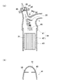
図2は、本実施形態に係る排気浄化装置の要部を示す図であり、(a)は拡大断面図、(b)は(a)のA―A線での端断面図である。排気管12の一部である排気路34は、図2中図示しないターボチャージャ27に接続する中空の上流側部材41と、上流側部材41に接続されている触媒保持部材42とから構成されている。触媒保持部材42には、固定部材43を介して酸化触媒31が設けられている。
2A and 2B are views showing the main part of the exhaust emission control device according to the present embodiment, in which FIG. 2A is an enlarged sectional view, and FIG. 2B is an end sectional view taken along line AA in FIG. An
上流側部材41について詳細に説明する。上流側部材41は、ターボチャージャ27側の一端である流入口44が図2中右向きに開口し、酸化触媒31側の他端の流出口45は図2中下向きに開口して上流側部材41が全体として緩やかに屈曲されるように構成されている。即ち、上流側部材41は、断面視において略L字状である。また、上流側部材41は、流入口44部分は狭く流出口45が触媒保持部材42と径が同一となるように広くなっている。
The
添加剤噴射路36は、排気路34の屈曲部の外側に、排気路34に連通(開口)して設けられている。即ち、図2中では、添加剤噴射路36は排気路34の左側壁面に、インジェクタ35が設けられたその基端部が上流側部材41の流入口44とは逆方向を向くように(左方向を向くように)設けられている。かかる構成により、流入口44から流入した排気ガスの主流とインジェクタ35から噴射され添加剤噴射路36を通過した燃料とは、上流側部材41の内径が広くなった部分で構成されている混合部46で混合された後に酸化触媒31に接触する。このようにインジェクタ35を添加剤噴射路36を介して設けることで、インジェクタ35が直接高温の排気ガスの主流に接触することを防止できる。
The
インジェクタ35は、詳細には、添加剤噴射路36の基端部に保持部材47により保持されている。保持部材47はフランジ部48を有し、このフランジ部48で図示しない固定部材により添加剤噴射路36に固定されている。また、インジェクタ35は、インジェクタ35の先端が添加剤噴射路36内に露出しない状態で保持部材47に保持されている。この保持部材47内部には、インジェクタ35の周囲を囲む冷却水路49が形成されている。インジェクタ35は、この冷却水路49により冷却されると共に、保持部材47により直接添加剤噴射路36内に露出しないように設けられていることで、常に過熱しないように保持されている。
Specifically, the
ここで、本実施形態では、上流側部材41に、排気ガスの一部を添加剤噴射路36に流入させるガイドとして機能するガイド部としての仕切り板50を設けている。仕切り板50は、添加剤噴射路36よりも上流側に、仕切り板50の上面が前記添加剤噴射路よりも上流側からの前記排気ガスに対向するように、上流側部材41の内壁に固定されている。また、仕切り板50は、仕切り板50の上流側の端部が排気ガスの主流の中心線L上に設置されるように設けている。
Here, in the present embodiment, the
この仕切り板50は、流入口側の排気路に対して対向しており、添加剤噴射路36側へゆるやかに屈曲した形状となっている。仕切り板50と、上流側部材41の上部内壁51(上流側部材41と添加剤噴射路36の接続部近辺)との距離は、流入口44側で広く、添加剤噴射路36側で狭くなっている。
The
図2(b)に示すように、この仕切り板50は、上流側部材41の対向する内壁面に鏡面対称となるように一つずつ設けられており、これら仕切り板50間は間隙が設けられている。即ち、仕切り板50は、上流側部材41の幅方向の両側にそれぞれ同じ方向に屈曲するように設けられている。
As shown in FIG. 2B, the
この仕切り板50を設けることで、排気ガスの一部は図3に示すように添加剤噴射路36の上流側内壁面に沿うように流入する。図3は、本実施形態における排気ガスの流れを説明するための拡大要部断面図である。流入口44から流入した排気ガスの主流は仕切り板50により分断される。この場合に、仕切り板50の上流側の端部が排気ガスの主流の中心線L上に設置されているので、排気ガスは略半分ずつに分断されている。
By providing this
排気ガスの一部G1は仕切り板50と上部内壁51との間を通過して上流側部材41の内壁に従って上昇し、排気ガスの残りG2はそのまま混合部46へ流入する。この場合、上述のように仕切り板50と上流側部材41の上部内壁51(添加剤噴射路36の接続部近辺)との距離は、流入口44側で広く、添加剤噴射路36側で狭くなっていることから、流入した排気ガスの一部G1は、流速を早めて添加剤噴射路36内へ添加剤噴射路36の上流側となる内壁面に沿って流入する。添加剤噴射路36に流入した排気ガスの一部G1は、そのまま添加剤噴射路36の内面形状に沿って添加剤噴射路36内を通過して混合部46へ流入する。混合部46へ流入した排気ガスの一部G1及び残りG2は、混合部46でそれぞれ燃料と混合される。
A part G1 of the exhaust gas passes between the
このように排気ガスの一部G1が添加剤噴射路36内に流入され、添加剤噴射路36内に燃料が留まることがなく、かつ、添加剤噴射路36の内壁に付着しているすすや燃料を掃き出すことができ、デポジットの堆積を防止でき、その結果、排気路34内への燃料の供給不良を防止することが可能である。この場合に、排気ガスはこの仕切り板50と上流側部材41の上部内壁51とで構成される通路を通過する。この通路は、上流側から下流側に向かって排気ガスの流量面積が漸次小さくなっていることから、排気ガスは流速を早めて添加剤噴射路36内に流入される。従って、添加剤噴射路36内により燃料が留まることがなく、かつ、添加剤噴射路36の内壁に付着しているすすや燃料をより多く掃き出すことができる。
In this way, a part of the exhaust gas G1 flows into the
なお、この仕切り板50の形状、設置位置は、排気ガスの一部を添加剤噴射路36内へ滑らかに流入させることができるものであれば本実施形態に限られない。また、本実施形態では仕切り板50を、仕切り板50の上流側端部が中心線L上にくるように設けて排気ガスのうち略半分が添加剤噴射路36へ流入するように構成したが、少なくとも排気ガスの一部を添加剤噴射路36へ流入させることができればよい。
The shape and installation position of the
次に、排気ガスの一部G1を添加剤噴射路36へ流入させる場合に、高温の排気ガスがインジェクタ35に接触するのを防止すべく、図4に示すように、添加剤噴射路36の突出部側には返し部を設けることが好ましい。返し部を設けることで、添加剤噴射路36に流入した排気ガスの一部G1が返し部で折り返されて添加剤噴射路36から流出する、即ち排気ガスのインジェクタ35側への流入を抑制するので、インジェクタ35との接触を防ぐことができる。図4に示す実施形態では、この返し部として、添加剤噴射路36を構成する壁面であって仕切り板50が設けられている側(上流側)の壁面を保持部材47の中心まで延設して延設部52として設けてある。
Next, in order to prevent the high-temperature exhaust gas from coming into contact with the
返し部としては、図5に示すような添加剤噴射路36を構成する壁面の一部を内側に凸の突起部53としたものも挙げられる。この場合には、図4に示した場合よりもよりインジェクタ35から距離を置いた位置で排気ガスを折り返して添加剤噴射路36から流出させることができるので、よりインジェクタ35と排気ガスとの接触を防止できる。
An example of the return portion is one in which a part of the wall surface constituting the
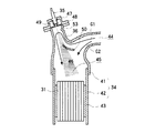
次いで、図6は、本発明のさらに別の実施形態を示すための概略図であり、(a)はその断面図、(b)はその要部の模式的斜視図、(c)は(a)のB−B線での端断面図である。この別の実施形態では、ガイド部としての仕切り板50(図2参照)の代わりに、上流側部材41に、上流側部材41の壁面に内側に凸となるように突出部54が成形されて設けられている。図6(b)に示すように、突出部54は、仕切り板50(図2参照)が設けられていた位置に成形により設けられたものであり、図6(c)に対向する面にも鏡面対称となるようにもう一つ突出部54が設けられ、互いに離間されている。この突出部54は、仕切り板50と同様に、流入口44から流入した排気ガスの主流を分断し、排気ガスの一部G1を突出部54の形状に従って上昇させて添加剤噴射路36内へ流入させるように、その形状や設置位置が設定されている。本実施形態におけるガイド部として機能する突出部54は、仕切り板50を設けることなく、突出部54を成形により内壁部に形成することが可能であるので、より簡易にガイド部を設けることが可能である。
6 is a schematic view showing still another embodiment of the present invention, in which (a) is a cross-sectional view thereof, (b) is a schematic perspective view of the main part thereof, and (c) is (a). It is an end sectional view in the BB line. In this other embodiment, instead of the partition plate 50 (see FIG. 2) as the guide portion, the
上記各実施形態において、仕切り板50、突出部54はそれぞれ離間して二つ設けてあるが、一つだけ設けてもよく、この場合、対向する壁面と離間して設けてもよく、かつ、壁面に連続するように設けてもよい。
In each of the above embodiments, the
以上、本実施形態について説明したが、本発明は、上述した実施形態に限定されるものではない。例えば、上述の実施形態では、排気浄化装置10として、排気管12に、排気浄化用触媒である酸化触媒31及びNOxトラップ触媒32と、排気浄化用フィルタであるDPF33とを、上流側から酸化触媒31、NOxトラップ触媒32、DPF33の順で配置した例を挙げたが、これら排気浄化用触媒及び排気浄化用フィルタの配置及び種類は特に限定されるものではない。
As mentioned above, although this embodiment was described, this invention is not limited to embodiment mentioned above. For example, in the above-described embodiment, as the
また、上述した実施形態では、NOxを分解(還元)する排気浄化用触媒として、燃料(軽油)を還元剤としてNOxを分解(還元)するNOxトラップ触媒を例示したが、これに限定されず、例えば、排気ガス中のNOxを選択的に触媒に吸着させ、還元剤としてアンモニアあるいは尿素をインジェクタから噴射してNOxを分解(還元)する、いわゆるSCR(Selective Catalytic Reduction)等であってもよい。 In the above-described embodiment, the NOx trap catalyst that decomposes (reduces) NOx using fuel (light oil) as a reducing agent is exemplified as the exhaust gas purification catalyst that decomposes (reduces) NOx, but is not limited thereto. For example, a so-called SCR (Selective Catalytic Reduction) that selectively adsorbs NOx in exhaust gas to a catalyst and injects ammonia or urea as a reducing agent from an injector to decompose (reduce) NOx may be used.
また、上述した実施形態では、添加剤として燃料を用いて説明したが、これに限らず、排気系に添加するものであれば、例えば、還元作用を目的とした還元剤でもよい。 In the above-described embodiment, the fuel is used as the additive. However, the present invention is not limited to this. For example, a reducing agent for reducing action may be used as long as it is added to the exhaust system.
本発明は、排気ガスからNOx等の物質を除去(削除)する排気浄化装置を利用するもの、例えば自動車製造分野で利用することができる。 INDUSTRIAL APPLICABILITY The present invention can be used in an apparatus that uses an exhaust purification device that removes (deletes) substances such as NOx from exhaust gas, for example, in the automobile manufacturing field.
10 排気浄化装置
11 エンジン
12 排気管
27 ターボチャージャ
31 酸化触媒
32 NOxトラップ触媒
34 排気路
35 インジェクタ
36 添加剤噴射路
41 上流側部材
42 触媒保持部材
43 固定部材
44 流入口
45 流出口
46 混合部
47 保持部材
48 フランジ部
49 冷却水路
50 仕切り板
51 上部内壁
52 延設部
53 突起部
54 突出部
DESCRIPTION OF
Claims (3)
前記排気路の前記添加剤噴射路よりも上流側に、前記排気ガスの一部を前記排気路の上流側となる前記添加剤噴射路の内壁面に沿うように誘導するガイド部が設けられていることを特徴とする排気浄化装置。 An exhaust passage connected to an exhaust port of the engine, an exhaust purification catalyst provided in the exhaust passage, an additive injection passage communicating with the exhaust passage upstream of the exhaust purification catalyst in the exhaust passage, An injector for injecting the additive into the additive injection path and supplying the additive to the exhaust gas purification catalyst;
A guide portion is provided on the upstream side of the additive injection path of the exhaust path so as to guide a part of the exhaust gas along the inner wall surface of the additive injection path on the upstream side of the exhaust path. An exhaust emission control device characterized by comprising:
前記添加剤噴射路は、前記添加剤噴射路側に誘導された排気ガスの前記インジェクタ側への流入を抑制する返し部を備えていることを特徴とする請求項1又は2記載の排気浄化装置。 The injector is provided on the opposite side of the exhaust path of the additive injection path,
The exhaust gas purification apparatus according to claim 1 or 2, wherein the additive injection path includes a return portion that suppresses inflow of exhaust gas guided to the additive injection path side to the injector side.
Priority Applications (1)
| Application Number | Priority Date | Filing Date | Title |
|---|---|---|---|
| JP2008195853A JP5141900B2 (en) | 2008-07-30 | 2008-07-30 | Exhaust purification device |
Applications Claiming Priority (1)
| Application Number | Priority Date | Filing Date | Title |
|---|---|---|---|
| JP2008195853A JP5141900B2 (en) | 2008-07-30 | 2008-07-30 | Exhaust purification device |
Publications (2)
| Publication Number | Publication Date |
|---|---|
| JP2010031779A true JP2010031779A (en) | 2010-02-12 |
| JP5141900B2 JP5141900B2 (en) | 2013-02-13 |
Family
ID=41736540
Family Applications (1)
| Application Number | Title | Priority Date | Filing Date |
|---|---|---|---|
| JP2008195853A Expired - Fee Related JP5141900B2 (en) | 2008-07-30 | 2008-07-30 | Exhaust purification device |
Country Status (1)
| Country | Link |
|---|---|
| JP (1) | JP5141900B2 (en) |
Cited By (12)
| Publication number | Priority date | Publication date | Assignee | Title |
|---|---|---|---|---|
| CN102803850A (en) * | 2010-03-24 | 2012-11-28 | 株式会社Ihi | Burner apparatus |
| WO2012172945A1 (en) * | 2011-06-15 | 2012-12-20 | 株式会社豊田自動織機 | Exhaust gas after-treatment device |
| JP2013002367A (en) * | 2011-06-16 | 2013-01-07 | Mitsubishi Motors Corp | Exhaust emission control device |
| JP2013007379A (en) * | 2011-06-07 | 2013-01-10 | Bosch Emission Systems Gmbh & Co Kg | Exhaust system |
| JP2013217350A (en) * | 2012-04-12 | 2013-10-24 | Hino Motors Ltd | Mixing structure |
| DE102014104224A1 (en) * | 2014-03-26 | 2015-10-01 | Friedrich Boysen Gmbh & Co. Kg | exhaust system |
| GB2539328A (en) * | 2015-06-10 | 2016-12-14 | Cummins Emission Solutions Inc | Aftertreatment exhaust separator and/or deflector |
| US10371032B2 (en) | 2016-09-16 | 2019-08-06 | Mazda Motor Corporation | Exhaust gas purifier for engine |
| JP2020514608A (en) * | 2016-12-22 | 2020-05-21 | パーキンズ エンジンズ カンパニー リミテッドPerkins Engines Company Limited | Flow hood assembly |
| JP2020133443A (en) * | 2019-02-15 | 2020-08-31 | トヨタ自動車株式会社 | Exhaust emission control device of internal combustion engine |
| US10967334B2 (en) | 2016-07-05 | 2021-04-06 | Daimler Ag | Mixing device and aftertreatment device |
| WO2023118216A1 (en) * | 2021-12-23 | 2023-06-29 | Daimler Truck AG | Chamber mixer for an exhaust after-treatment system of a motor vehicle |
Citations (7)
| Publication number | Priority date | Publication date | Assignee | Title |
|---|---|---|---|---|
| JP2003013729A (en) * | 2001-06-29 | 2003-01-15 | Mitsubishi Motors Corp | Exhaust emission purifier of internal combustion engine |
| JP2003278530A (en) * | 2002-03-20 | 2003-10-02 | Nippon Soken Inc | Reducing agent supplying device |
| JP2006077691A (en) * | 2004-09-10 | 2006-03-23 | Toyota Motor Corp | Exhaust emission control system for diesel engine |
| JP2007016613A (en) * | 2005-07-05 | 2007-01-25 | Hino Motors Ltd | Exhaust gas additive feeder |
| JP2007327377A (en) * | 2006-06-07 | 2007-12-20 | Hitachi Ltd | Exhaust emission control device |
| JP2009036150A (en) * | 2007-08-03 | 2009-02-19 | Toyota Motor Corp | Reducer-adding device of internal combustion engine |
| JP2009156073A (en) * | 2007-12-25 | 2009-07-16 | Mitsubishi Motors Corp | Exhaust emission control device for internal combustion engine |
-
2008
- 2008-07-30 JP JP2008195853A patent/JP5141900B2/en not_active Expired - Fee Related
Patent Citations (7)
| Publication number | Priority date | Publication date | Assignee | Title |
|---|---|---|---|---|
| JP2003013729A (en) * | 2001-06-29 | 2003-01-15 | Mitsubishi Motors Corp | Exhaust emission purifier of internal combustion engine |
| JP2003278530A (en) * | 2002-03-20 | 2003-10-02 | Nippon Soken Inc | Reducing agent supplying device |
| JP2006077691A (en) * | 2004-09-10 | 2006-03-23 | Toyota Motor Corp | Exhaust emission control system for diesel engine |
| JP2007016613A (en) * | 2005-07-05 | 2007-01-25 | Hino Motors Ltd | Exhaust gas additive feeder |
| JP2007327377A (en) * | 2006-06-07 | 2007-12-20 | Hitachi Ltd | Exhaust emission control device |
| JP2009036150A (en) * | 2007-08-03 | 2009-02-19 | Toyota Motor Corp | Reducer-adding device of internal combustion engine |
| JP2009156073A (en) * | 2007-12-25 | 2009-07-16 | Mitsubishi Motors Corp | Exhaust emission control device for internal combustion engine |
Cited By (24)
| Publication number | Priority date | Publication date | Assignee | Title |
|---|---|---|---|---|
| CN102803850B (en) * | 2010-03-24 | 2015-03-25 | 株式会社Ihi | Burner apparatus |
| JPWO2011118635A1 (en) * | 2010-03-24 | 2013-07-04 | 株式会社Ihi | Burner equipment |
| JP5494795B2 (en) * | 2010-03-24 | 2014-05-21 | 株式会社Ihi | Burner equipment |
| US8827694B2 (en) | 2010-03-24 | 2014-09-09 | Ihi Corporation | Burner device |
| CN102803850A (en) * | 2010-03-24 | 2012-11-28 | 株式会社Ihi | Burner apparatus |
| JP2013007379A (en) * | 2011-06-07 | 2013-01-10 | Bosch Emission Systems Gmbh & Co Kg | Exhaust system |
| WO2012172945A1 (en) * | 2011-06-15 | 2012-12-20 | 株式会社豊田自動織機 | Exhaust gas after-treatment device |
| JP2013002367A (en) * | 2011-06-16 | 2013-01-07 | Mitsubishi Motors Corp | Exhaust emission control device |
| JP2013217350A (en) * | 2012-04-12 | 2013-10-24 | Hino Motors Ltd | Mixing structure |
| CN104321505A (en) * | 2012-04-12 | 2015-01-28 | 日野自动车株式会社 | Mixing structure |
| US9649595B2 (en) | 2012-04-12 | 2017-05-16 | Hino Motors, Ltd. | Mixing structure |
| EP2857644A4 (en) * | 2012-04-12 | 2016-03-02 | Hino Motors Ltd | Mixing structure |
| DE102014104224A1 (en) * | 2014-03-26 | 2015-10-01 | Friedrich Boysen Gmbh & Co. Kg | exhaust system |
| GB2539328A (en) * | 2015-06-10 | 2016-12-14 | Cummins Emission Solutions Inc | Aftertreatment exhaust separator and/or deflector |
| CN106246308A (en) * | 2015-06-10 | 2016-12-21 | 康明斯排放处理公司 | Post processing discharge air separator and/or deflector |
| US9816421B2 (en) | 2015-06-10 | 2017-11-14 | Cummins Emission Solutions Inc. | Aftertreatment exhaust separator and/or deflector |
| CN106246308B (en) * | 2015-06-10 | 2019-10-29 | 康明斯排放处理公司 | Post-process discharge air separator and/or deflector |
| GB2539328B (en) * | 2015-06-10 | 2020-12-23 | Cummins Emission Solutions Inc | Aftertreatment exhaust separator and/or deflector |
| US10967334B2 (en) | 2016-07-05 | 2021-04-06 | Daimler Ag | Mixing device and aftertreatment device |
| EP3482051B1 (en) * | 2016-07-05 | 2021-04-28 | Daimler AG | Mixing device and aftertreatment device |
| US10371032B2 (en) | 2016-09-16 | 2019-08-06 | Mazda Motor Corporation | Exhaust gas purifier for engine |
| JP2020514608A (en) * | 2016-12-22 | 2020-05-21 | パーキンズ エンジンズ カンパニー リミテッドPerkins Engines Company Limited | Flow hood assembly |
| JP2020133443A (en) * | 2019-02-15 | 2020-08-31 | トヨタ自動車株式会社 | Exhaust emission control device of internal combustion engine |
| WO2023118216A1 (en) * | 2021-12-23 | 2023-06-29 | Daimler Truck AG | Chamber mixer for an exhaust after-treatment system of a motor vehicle |
Also Published As
| Publication number | Publication date |
|---|---|
| JP5141900B2 (en) | 2013-02-13 |
Similar Documents
| Publication | Publication Date | Title |
|---|---|---|
| JP5141900B2 (en) | Exhaust purification device | |
| JP5561486B2 (en) | Exhaust purification device | |
| JP4450257B2 (en) | Exhaust purification device | |
| JP5013121B2 (en) | Exhaust purification device | |
| JP2013241859A (en) | Exhaust gas purification system and method for purifying exhaust gas | |
| JP4784761B2 (en) | Exhaust purification device | |
| JP2013234639A (en) | System and method of cleaning exhaust gas | |
| KR20110014524A (en) | Exhaust gas purifing apparatus | |
| JP4638892B2 (en) | Exhaust gas purification device for internal combustion engine | |
| JP2008128046A (en) | Exhaust gas purification device | |
| KR101795402B1 (en) | Exhaust system | |
| US8986636B2 (en) | Apparatus and method for filtering engine exhaust gases | |
| JP2000199423A (en) | Exhaust emission control device for diesel engine | |
| JP5900728B2 (en) | Engine exhaust purification system | |
| JP3545712B2 (en) | Exhaust gas purification device | |
| JP5605578B2 (en) | Exhaust purification device | |
| JP5019069B2 (en) | Exhaust purification device | |
| JP2009150279A (en) | Exhaust gas treatment device | |
| JP5041168B2 (en) | Exhaust purification device | |
| JP4671048B2 (en) | Exhaust purification device | |
| JP2008151039A (en) | Exhaust emission control device | |
| US20090151340A1 (en) | Exhaust gas purification device | |
| JP4737463B2 (en) | Exhaust purification device | |
| JP4924844B2 (en) | Exhaust purification device | |
| JP4844766B2 (en) | Exhaust purification device |
Legal Events
| Date | Code | Title | Description |
|---|---|---|---|
| A621 | Written request for application examination |
Free format text: JAPANESE INTERMEDIATE CODE: A621 Effective date: 20100826 |
|
| A977 | Report on retrieval |
Free format text: JAPANESE INTERMEDIATE CODE: A971007 Effective date: 20110826 |
|
| A131 | Notification of reasons for refusal |
Free format text: JAPANESE INTERMEDIATE CODE: A131 Effective date: 20120229 |
|
| A521 | Written amendment |
Free format text: JAPANESE INTERMEDIATE CODE: A523 Effective date: 20120418 |
|
| TRDD | Decision of grant or rejection written | ||
| A01 | Written decision to grant a patent or to grant a registration (utility model) |
Free format text: JAPANESE INTERMEDIATE CODE: A01 Effective date: 20121024 |
|
| A01 | Written decision to grant a patent or to grant a registration (utility model) |
Free format text: JAPANESE INTERMEDIATE CODE: A01 |
|
| A61 | First payment of annual fees (during grant procedure) |
Free format text: JAPANESE INTERMEDIATE CODE: A61 Effective date: 20121106 |
|
| FPAY | Renewal fee payment (event date is renewal date of database) |
Free format text: PAYMENT UNTIL: 20151130 Year of fee payment: 3 |
|
| R150 | Certificate of patent or registration of utility model |
Ref document number: 5141900 Country of ref document: JP Free format text: JAPANESE INTERMEDIATE CODE: R150 Free format text: JAPANESE INTERMEDIATE CODE: R150 |
|
| LAPS | Cancellation because of no payment of annual fees |