JP2010029991A - Robot system for article transfer - Google Patents
Robot system for article transfer Download PDFInfo
- Publication number
- JP2010029991A JP2010029991A JP2008195526A JP2008195526A JP2010029991A JP 2010029991 A JP2010029991 A JP 2010029991A JP 2008195526 A JP2008195526 A JP 2008195526A JP 2008195526 A JP2008195526 A JP 2008195526A JP 2010029991 A JP2010029991 A JP 2010029991A
- Authority
- JP
- Japan
- Prior art keywords
- bucket
- robot
- article
- loading
- unit
- Prior art date
- Legal status (The legal status is an assumption and is not a legal conclusion. Google has not performed a legal analysis and makes no representation as to the accuracy of the status listed.)
- Granted
Links
Images


Landscapes
- Manipulator (AREA)
- Warehouses Or Storage Devices (AREA)
Abstract
Description
本発明は、たとえばベアリングのインナーレースおよびアウターレース、ならびにエンジンのコンロッドなどの熱間鍛造製品を、受渡ステーションにおいて物品供給手段から受取り、所定の積込み容器に積付ける物品移載用ロボット装置に関し、特にそのロボットハンド部の構造に関する。 The present invention relates to an article transfer robot apparatus that receives hot forged products such as inner races and outer races of bearings, and connecting rods of engines, for example, from article supply means at a delivery station and loads them in a predetermined loading container. It relates to the structure of the robot hand.
産業用ロボットは、各種製造分野で広く利用されている。これらの産業用ロボットの典型的な従来技術は、特許文献1に示されている。また、特許文献2,3には、このようなロボット装置におけるロボットハンド部の衝撃吸収機構の例が、さらに、特許文献4,5には、ロボットハンド部の着脱自在な機構の例が示されている。
Industrial robots are widely used in various manufacturing fields. A typical prior art of these industrial robots is shown in
図10は、前記のような鍛造製品の製造工場で採用されている物品移載用ロボット装置の一例を示している。ロボット装置100は、ロボットベース部101と、前記ロボットベース部101に回動自在に連結された多関節ロボットアーム部102と、前記ロボットアーム部102の先端に回動自在に連結されたロボットハンド部103とを含む。ロボットハンド部103は、バケット保持部104と、バケット保持部104に保持されたバケット部105とからなる。
FIG. 10 shows an example of an article transfer robot apparatus employed in a forging product manufacturing factory as described above. The
前記ロボット装置100は、図示しない物品受渡ステーションにおいて、図示しない物品供給コンベアから供給される物品(以下、ワークと記す)Wを、前記バケット部105に受取って収容し、予めティーチングされた動作プログラムによってロボットアーム部102を動作させて、所定の位置に設置された積込み容器である積込みパレット106内に順次積付けるように稼動する。図10では、積込みパレット106内の位置に応じてロボットハンド部103の角度を適宜設定させることによって、バケット部105を傾斜させ、ワークWを積込みパレット106内に投入し、積付けている状態を示している。
The
図10に示すようなロボット装置100の場合、積込みパレット106内の所定の位置にワークWを投入して積込みする際、積込みパレット106の囲い部の制約などがあるため、積込み位置に応じてロボットハンド部103の角度を適宜設定する必要がある。また、場所によっては囲い部に制限されてロボットハンド部103の傾き角度が充分に確保されず、そのため、高い位置からワークWを投入せざるを得ない場合も生じる。図10は、ロボットハンド部104の一部が積込みパレット106の囲い部と干渉している状態を示している。このように高い位置からワークWを投入すると、ワークWに打痕が生じ、製品品質の低下の原因となる。また、ロボットハンド部104と積込みパレット106との干渉のために、ロボットハンド部104の積込みパレット106内での動作範囲が狭められ、積込みパレット106内でのワークWの均一な積付けができなくなることがある。
In the case of the
前記特許文献1〜5の各先行技術は、このような積込みパレット106の囲い部の制約から、物品を高い位置から落下投入せざるを得ないなどの問題点について、その解決手段を特に提案するものではない。
Each of the prior arts of
本発明の目的は、簡易な方法で物品に打痕などを生じさせず、均一かつ効率的な積付けを可能とする物品移載用ロボット装置を提供することである。 An object of the present invention is to provide an article transfer robot apparatus that enables uniform and efficient loading without causing dents or the like on an article by a simple method.
本発明に係る物品移載用ロボット装置は、物品受渡ステーションにおいて物品供給手段から受取った物品を、所定の積込み容器に積付ける物品移載用ロボット装置であって、
ロボットベース部と、前記ロボットベース部に回動自在に連結された多関節ロボットアーム部と、前記ロボットアーム部の先端に回動自在に連結されたロボットハンド部とを含み、
前記ロボットハンド部は、バケット保持部と、前記物品を収容するためのバケット部とからなり、
前記バケット部は、バケット保持部に対して傾動可能に保持され、かつ角度調整駆動部によって傾き角度の調整が可能とされていることを特徴とする物品移載用ロボット装置である。
An article transfer robot apparatus according to the present invention is an article transfer robot apparatus for loading an article received from an article supply means at an article delivery station into a predetermined loading container,
A robot base part, an articulated robot arm part rotatably connected to the robot base part, and a robot hand part rotatably connected to a tip of the robot arm part,
The robot hand part is composed of a bucket holding part and a bucket part for accommodating the article,
The bucket unit is an article transfer robot device, wherein the bucket unit is tiltably held with respect to the bucket holding unit, and an inclination angle can be adjusted by an angle adjustment driving unit.
本発明に従えば、物品供給手段から供給される物品は、物品受渡ステーションにおいて、ロボットハンド部のバケット部に収容される。そして、多関節ロボットアーム部の動作によって、ロボットハンド部が所定の積込み容器内に位置し、バケット部から収容されている物品が積込み容器内に積付けられる。このとき、バケット部は、バケット保持部に対して傾動可能に保持され、かつ角度調整駆動部によって傾き角度の調整が可能とされているから、バケット部を適宜角度に傾斜させることによって、物品を、積込み容器内の底部に、あるいは既に積付けられた物品がある場合はその上に、接近させた状態で、投入積付けることができる。したがって、物品が落下によって打痕を生じることが少なく、移載時における品質の劣化を来たす懸念がない。しかも、ロボットハンド部を傾斜させることなく垂直な状態で積込み容器内に位置させ、動作させることができるから、ロボットハンド部が積込み容器の囲い部などと干渉しないようにすることが簡易になされる。これによって、ロボットハンド部の動作自由度が増し、積込み容器内のスペースを無駄なく使い、物品の均一な積付けを実現することができる。 According to the present invention, the articles supplied from the article supply means are accommodated in the bucket portion of the robot hand unit at the article delivery station. Then, by the operation of the articulated robot arm unit, the robot hand unit is positioned in a predetermined loading container, and the articles accommodated from the bucket unit are loaded in the loading container. At this time, the bucket portion is tiltably held with respect to the bucket holding portion, and the inclination angle can be adjusted by the angle adjustment driving portion. Therefore, by tilting the bucket portion to an appropriate angle, the article can be In the case where there is an article already loaded on the bottom of the loading container, it can be loaded in an approached state. Therefore, the article is less likely to cause dents due to dropping, and there is no concern of quality deterioration during transfer. In addition, since the robot hand portion can be positioned and operated in a vertical state without tilting, it is easy to prevent the robot hand portion from interfering with the enclosure portion of the loading container. . As a result, the degree of freedom of operation of the robot hand portion is increased, the space in the loading container can be used without waste, and uniform loading of articles can be realized.
また本発明は、前記角度調整駆動部が、非作動の状態では、バケット部が自重で傾動するように構成されていることを特徴とする。 In the invention, it is preferable that the angle adjustment drive unit is configured such that the bucket portion tilts by its own weight when the angle adjustment drive unit is not operated.
本発明に従えば、ロボットハンド部を積込み容器内に位置させ、バケット部を所定の被積付位置の表面に接近させた状態で角度調整駆動部を非作動状態とし、かつロボットハンド部をそのまま垂直方向に上昇させることによって、バケット部がバケット保持部に対し相対的に自重で下方に傾動する。したがって、バケット部内の物品はこの傾動に伴い滑り降り出すが、前記積付け位置との落差は小さい状態であるから、落下によるダメージを受けることが少なく、積付け時の打痕の発生をより少なくすることができる。 According to the present invention, the robot hand unit is positioned in the loading container, the angle adjustment drive unit is deactivated with the bucket unit approaching the surface of the predetermined loading position, and the robot hand unit is left as it is. By raising in the vertical direction, the bucket portion tilts downward with its own weight relative to the bucket holding portion. Therefore, although the article in the bucket part starts to slide down with this tilting, the drop with respect to the loading position is small, so that it is less likely to receive damage due to dropping, and the occurrence of dents during loading is reduced. be able to.
また本発明は、前記バケット部が、バケット保持部に対して着脱手段を介して着脱自在に保持されていることを特徴とする。 Further, the present invention is characterized in that the bucket part is detachably held with respect to the bucket holding part via an attaching / detaching means.
本発明に従えば、前記受渡ステーションに複数のバケット部を待機させるよう構成することによって、積付け作業を実施している間に待機中のバケット部に前記物品供給手段から物品を供給して収容・待機させておき、仕掛かり中の積付け作業が終了すると、受渡ステーションにおいてバケット部を待機中のものと着脱交換するだけで、効率の良い積付け作業を実施することができる。また、物品の種類に応じたバケット部を複数準備しておき、これらバケット部を適宜選択装着することによって、物品の特性に合った積付け作業を実施することができる。 According to the present invention, by configuring the delivery station to wait for a plurality of bucket units, the articles are supplied from the article supply means to the bucket unit that is waiting while the loading operation is being performed. -When the loading operation in progress is completed by waiting, the efficient loading operation can be performed by simply attaching and detaching the bucket unit to the waiting unit at the delivery station. Further, by preparing a plurality of bucket portions according to the type of the article and appropriately selecting and attaching these bucket sections, it is possible to perform a stacking operation that matches the characteristics of the article.
また本発明は、前記ロボットハンド部が、前記バケット部が受けた衝撃を吸収する衝撃吸収手段を備えていることを特徴とする。 Further, the present invention is characterized in that the robot hand portion includes an impact absorbing means for absorbing an impact received by the bucket portion.
本発明に従えば、前記ロボットハンド部を積込み容器内に挿入させてゆく過程などにおいて、前記バケット部が積込み容器の囲い部や、底部の既に積付けられた物品などに不用意に当接しても、衝撃吸収手段によってこの衝撃が吸収され、バケット部やバケット保持部の損壊を未然に防止することができる。 According to the present invention, in the process of inserting the robot hand part into the loading container, the bucket part inadvertently comes into contact with the enclosure part of the loading container or the article already loaded on the bottom part. However, this impact is absorbed by the impact absorbing means, and damage to the bucket part and the bucket holding part can be prevented beforehand.
また本発明は、前記ロボットハンド部が、前記バケット部を傾動させて積込み容器内に物品を積付ける際に、バケット部が積込み容器内の積付け対象部に接触したときの高さを検出する高さ検出手段を備えることを特徴とする。 In the present invention, when the robot hand unit tilts the bucket unit and loads an article into the loading container, the robot hand unit detects a height when the bucket unit comes into contact with the loading target unit in the loading container. A height detection means is provided.
このような構成は、バケット部が、不用意に当接したことを認識するためのセンサー(88)によって実現され、その検知信号によって、ロボットの動作を停止させて、次のステップへ移ることができる。 Such a configuration is realized by a sensor (88) for recognizing that the bucket portion has inadvertently contacted, and the operation of the robot is stopped by the detection signal, and the process proceeds to the next step. it can.
本発明に従えば、物品の積付けの際に、バケット部が傾動して、積込み容器内の積付け対象部(積込み容器の底部、あるいは既に積付けられている物品の表面)に接触し、一度に急激な角度にバケットを傾動させないようにして、バケット内の物品が落下することを防止する。その後、ロボットがハンドを引き上げることによって、徐々にバケットを傾斜させ、バケット内の物品がゆっくり滑り降りる状態で、容器内に積み付けられる。また、ロボットがハンドを引き上げることによって、最終的にバケットがフルに傾斜した時点で、センサー(87)が検知し、バケットが接触した下方の物品表面高さを知ることができる。この高さ情報に基づき、積付け作業を実行中の物品高さを加えることによって、次の積付け位置を認識することができる。 According to the present invention, when the article is loaded, the bucket portion tilts and comes into contact with the loading target portion in the loading container (the bottom of the loading container or the surface of the article already loaded). By preventing the bucket from tilting at a sudden angle at a time, articles in the bucket are prevented from falling. Thereafter, the robot pulls up the hand, thereby gradually tilting the bucket, and the articles in the bucket are loaded into the container in a state where the articles slowly slide down. Further, when the robot pulls up the hand, the sensor (87) detects when the bucket is finally fully inclined, and the lower article surface height with which the bucket is in contact can be known. Based on this height information, the next loading position can be recognized by adding the height of the article being loaded.
本発明に従えば、物品受渡ステーションにおいて、物品供給手段からバケット部に供給された物品は、多関節ロボットアーム部の動作によって、バケット部から積込み容器内に積付けられる。このとき、バケット部を適宜角度に傾斜させることによって、物品を、積込み容器内の底部に、あるいは、既に積付けられた物品がある場合はその上に、接近させた状態で、物品を積付けることができる。 According to the present invention, in the article delivery station, the article supplied from the article supply means to the bucket unit is loaded from the bucket unit into the loading container by the operation of the articulated robot arm unit. At this time, by inclining the bucket part at an appropriate angle, the article is loaded at the bottom in the loading container or, if there is an already loaded article, in an approached state. be able to.
したがって、物品に落下による打痕を生じることが少なく、移載時における品質の劣化を来たす懸念がない。しかも、ロボットハンド部を傾斜させることなく垂直な状態で積込み容器内に位置させ、動作させることができるので、ロボットハンド部が積込み容器の囲い部などと干渉しないようにすることが簡易になされる。これによって、ロボットハンド部の動作自由度が増し、積込み容器内のスペースを無駄なく使い、物品の均一な積付けを実現することができる。 Therefore, there are few dents due to dropping on the article, and there is no concern of quality deterioration during transfer. In addition, since the robot hand portion can be positioned and operated in the loading container in a vertical state without being inclined, it is easy to prevent the robot hand portion from interfering with the enclosure portion of the loading container. . As a result, the degree of freedom of operation of the robot hand portion is increased, the space in the loading container can be used without waste, and uniform loading of articles can be realized.
図1は、本発明の実施の一形態である物品移載用ロボット装置2が設置された作業室1を概略的に示す側面図であり、図2は作業室1の平面図である。物品移載用ロボット装置2は、作業室1内に設置された物品受渡ステーション3において、図示しない鍛造設備などから作業室1に物品供給手段であるワーク供給コンベア4によって搬入された物品(以下、「ワーク」と記す場合がある。)Wを、積込み容器である所定の積込みパレット5,6に順次積付けるものである。積込みパレット5,6は、作業室1の床面であって、物品移載用ロボット装置2のロボットベース20に左右対称に設けられた2個所のパレットヤード50,60に位置決めされて載置される。これらのパレットヤード50,60は、2個所に限定されず、1個所あるいは3個所以上であっても良く、扱うワークの特性や処理システムの規模などに応じて適宜定められる。作業室1には、作業者が出入りするためのドア1a、および積込みパレット5,6を搬出入するための図示しない機材搬出入用ドアなどが設けられる。
FIG. 1 is a side view schematically showing a
物品受渡ステーション3は、作業室1の床面に設置固定された平面形状が方形の基台30と、前記基台30に対して前記ワーク供給コンベア4に直交する方向aに往復水平移動自在でかつ上下昇降自在に支持されたスライダ31と、前記スライダ31上にスライド方向aに並設された2個の傾斜したバケット受台32,33とを含んで構成されている。
The
トラバーサーとしてのスライダ31の水平移動範囲は、2個のバケット受台32,33のいずれかが、ワーク供給コンベア4のワーク供給方向bの延長上のワーク受取位置34に位置し得るよう設定される。図2では、バケット受け台33がこのワーク受取位置34にあり、後述するバケット部9を支持して、ワーク供給コンベア4から供給されるワークWを収容し得る状態とされている。また、他方のバケット受台32は、ワーク受取位置34から退避した位置にあり、ロボット装置2によって積付けが完了した空のバケット部9を受取るために待機している状態にあることを示している。
The horizontal movement range of the
前記ワーク供給コンベア4のワーク排出側には、前記物品受渡ステーション3のワーク受渡位置34に架け渡されるワーク投入シュート7が連設されている。ワーク投入シュート7は、ワーク供給コンベア4の架台40に、図示しないピストン機構などによって、上下昇降可能に支持されたブラケット71にエアシリンダ72を介して連結され、ワーク投入角度の調整、および後述するバケット部9の交換の際の、バケット部9との非干渉位置への退避などが可能とされている。
On the workpiece discharge side of the
また、前記ワーク供給コンベア4のワーク排出側端部上方には、投入されるワークWを逐次検出するワーク通過センサ41が設置されている。ワーク通過センサ41としては、光学式のセンサが望ましいが、これに限定されるものではない。ワーク通過センサ41の検出情報は、図示しないロボットコントローラに入力され、ロボットコントローラにおいて図示しないカウンターによってワークWの通過個数を計数するように構成されている。
A
物品移載用ロボット装置2は、ロボットベース部20と、前記ロボットベース部20に回動自在に連結された多関節ロボットアーム部21と、前記ロボットアーム部21の先端に、手首部22を介して回動自在に連結されたロボットハンド部23とを含む。物品移載用ロボット装置2は、多関節6軸ロボットによって実現され、作業室1の外に設置された図示しないロボットコントローラにおけるティーチングペンダントによって教示され、所定の動作プログラムに基づき動作する。ロボットハンド部23は、バケット保持部8と、バケット保持部8に着脱自在に保持されたバケット部9とからなる。
The article
図3はロボットハンド部23の側面図であり、図4はロボットハンド部23のバケット部9をバケット保持部8から分離した状態を示す側面図であり、図5はロボットハンド部23の断面図である。前記手首部22の先端には、関節部24を介してハンド取付ブラケット80が連結されている。このハンド取付ブラケット80には、衝撃吸収シリンダ81、複数(本実施形態では2)のガイドロッド82および可動支持板83を含む衝撃吸収手段10が設けられる。前記衝撃吸収シリンダ80のピストン棒の軸線および各ガイドロッド82の軸線は、互いに平行である。衝撃吸収手段10は、ワークWの移載動作時に、バケット部9などに不用意に衝撃力が作用したとき、衝撃吸収シリンダ81がそのダンパー効果によって衝撃を吸収し、バケット部9の損壊を未然に防止するよう機能する。
3 is a side view of the
また、前記可動支持板83には、バケット部9を着脱自在に保持するための着脱手段11が支持されている。着脱手段11は、空気圧によって作動するクランプシリンダ84、一対のクランプアーム85およびクランプフィンガ86を含む。着脱手段11は、通常のワークWの移載動作時には、クランプシリンダ84の駆動によって一対のクランプアーム85が互いに接近するよう付勢され、一対のクランプフィンガ86が後述するバケット支持ブラケット90を挟着し、バケット部9が吊下された状態で着脱可能に連結される。
The
さらに、図4に示すように、クランプシリンダ84が前述とは逆に駆動することによって、クランプアーム85が相互に開き、クランプフィンガ86の把持が解除されると、バケット部9がバケット保持部8から離脱される。このようなバケット部9の着脱は、前記受渡ステーション3において、ロボット装置2が、ワークWが収容されたバケット部9をバケット受台32(33)から取出し、あるいは、積付け完了後の空のバケット部9をバケット受台32(33)にセットする際に実行される。
Further, as shown in FIG. 4, when the
前記バケット部9は、前記クランプフィンガ86に着脱自在に連結される逆U字状のバケット支持ブラケット90と、バケット支持ブラケット90にヒンジピン91を介して傾動自在に支持されるバケット本体92と、バケット支持ブラケット90に固定され、バケット本体92の開口部を覆うカバー体93と、バケット本体92の背面に連結ブラケット94およびレバーピン95を介して連結されたアングルレバー96とを含む。
The
バケット本体92は、傾動側先端部と上面部とが開口された断面略L字状のいわばショベル形状を成し、前記カバー体93はこの開口部を覆うようにバケット支持ブラケット90に固着されている。カバー体93は、バケット支持ブラケット90に固着され、バケット本体92はバケット支持ブラケット90に対して傾動自在に支持されているから、バケット本体92がヒンジピン91の軸線まわりに下方へ傾動すると、図3の2点鎖線で示すように、バケット本体92からカバー体93が離反して開口が形成される。
The bucket
連結ブラケット94は、ブラケット本体92の背面に突出するよう固着され、アングルレバー96は、その基部が連結ブラケット94にレバーピン95を介して連結されている。さらに、アングルレバー96のほぼ中央部から前記レバーピン95が挿通する両端部に向けて、長手方向に沿って延びる長孔97が形成され、この長孔97には前記バケット支持ブラケット90に取付けられた規制ピン98が相対的に摺動可能に挿入されている。アングルレバー96の上端部には、その上端面から周面が若干突出するようローラ99が回転自在に取付けられている。
The
前記衝撃吸収手段10の可動支持板83には、バケット部9におけるバケット本体92の角度調整駆動部12が装着されている。角度調整駆動部12は、空気圧によって作動する駆動シリンダ13と、ガイドロッド14と、駆動シリンダ13の伸縮ロッド13aおよびガイドロッド14の先端に固着された作用板15とを含む。作用板15は、伸縮ロッド13aの伸張によって前記アングルレバー96の上端に設けられる前記ローラ99に当接してアングルレバー96を押下げ、これによってバケット本体92を先端部側が上向きに角変位するように傾動させる。駆動シリンダ13に作動圧がかかった状態では、バケット本体92をその先端部側が上向きとなった傾斜状態に維持する。また、駆動シリンダ13が、作動圧がかからず非作動の状態では、バケット本体92の先端部側が自重で下向きに傾動し、これによって、伸縮ロッド13aが収縮する。すなわち、角度調整駆動部12は、伸縮ロッド13aを伸張/縮退させることによって、バケット本体92の傾動角度の調整を成すよう構成されている。
The
前記作用板15の側部には、センサ検知板15aが付設され、前記衝撃吸収手段10の可動支持板83には、渦電流検出式の近接スイッチ87が高さ検出手段として設けられる。この近接スイッチ87は、前述のように伸縮ロッド13aが縮退して作用板15が傾動上限位置に達したとき、センサ検知板15aを検出するように構成されている。また、可動支持板83の側部に近接するロボットハンド部23の固定側には、前記衝撃が加わった際の可動支持板83の上方への変位を検出する渦電流検出式の近接スイッチ88が衝撃検出手段として取付けられている。さらに、前記着脱手段11に支持部には、各クランプフィンガ86の開閉状態を検出する開閉検出スイッチ89が設けられる。
A sensor detection plate 15 a is attached to the side of the
前記バケット本体92は、前述のように断面略L字状のいわばショベル形状を成し、バケット支持ブラケット90にヒンジピン91を介して傾動自在に支持されているが、アングルレバー96を介した角度調整駆動部12との連繋関係がない状態では、ヒンジピン91を支点として先端部が自重で下向きに傾動するよう構成されている。すなわち、図6に示すように、バケット本体92内の奥部に収容されて保持されたワークWの重量、アングルレバー96の重量、角度調整駆動部12の非作動の状態での抵抗力などの合力による回転モーメントに抗する抵抗モーメントがバケット本体92に発生するように、バケット本体92の先端側の両外側起立壁部には、カウンタウェイト92aが固着されている。これによって、角度調整駆動部12が非作動の状態では、ヒンジピン91を支点としてバケット本体92の先端部が自重で下向きに傾動することが可能とされる。
The bucket
このようなカウンタウェイト92aの重量は、対象とするワークWの種類や収容量によって適宜選択される。また、バケット本体92の底面部を構成する部材としては、ワークWの滑り性が良く、耐摩耗性に優れた材質のものが用いられる。ワークWが熱間鍛造品の場合は、急冷されることなく、1200℃程度の熱を保有した状態で供給されてくるので、優れた耐熱性も求められる。
The weight of the
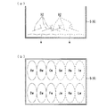
図7(a)の断面図および図7(b)の平面図は、積込みパレット5(または6)にワークWを積付ける作業手順の一例を模式的に示している。図7(b)に示すように、積込みパレット5(6)内の所定の積付けエリアAw〜Lwは、予め座標値によってロボット装置2にティーチングされており、ロボット装置2は、各エリアAw〜Lw毎にロボットハンド23を位置付け、バケット本体92を傾動させて、ワークWの積付け動作が実行される。このとき、積付けスペースを有効に使用するため、図7(a)に示すように、エリアAw〜Fwと、エリアGw〜Lwとは、バケット本体92の向きを180°反転させた積付け状態で行うことが望ましい。図7(a)および図7(b)では、1点鎖線と破線とによるバケット本体92およびエリアAw〜Lwによって、この異なった積付け状態を模式的に区別して表している。これによって、ロボットハンド部23と積込みパレット5(6)の囲い部との干渉も少なくすることができるとともに、積込みパレット5(6)のスペースを有効に活用し、均一な積付けが可能となる。
The sectional view of FIG. 7A and the plan view of FIG. 7B schematically show an example of a work procedure for loading the workpiece W on the loading pallet 5 (or 6). As shown in FIG. 7B, predetermined loading areas Aw to Lw in the loading pallet 5 (6) are taught to the
次に、以上のような構成の物品移載用ロボット装置2を用いて、ワーク供給コンベア4から供給されるワークWを積込みパレット5,6に積付ける工程について、図8の断面図および図9Aおよび図9Bのフローチャートをも参照して説明する。物品移載用ロボット装置2は、その動作を制御するための図示しない制御装置を備え、この制御装置はたとえばパーソナルコンピュータによって実現される。このパーソナルコンピュータは、ロボットコントローラと本実施形態の物品移載作業を行うためのプログラムをリンクさせて実行することができる。
Next, regarding the process of loading the workpiece W supplied from the
物品移載用ロボット装置2は、図9Aおよび図9Bに示すように、ロボット装置2が原点位置にあり、バケット本体92が2個とも受渡ステーション3のトラバーサとも呼ばれるスライダ31上にあることが開始条件とされる。そして、図示しないロボットコントローラにおいてスタート操作がされると(ステップS1)、ワーク供給コンベア4および物品移載用ロボット装置2が起動する(ステップS2)。ワーク供給コンベア4から供給されるワークWは、ワーク供給コンベア4の先端側に設置されたワーク通過センサ41によって検出される(ステップS3)。最初の1個が検出されると、前記制御装置のカウンタ(図示せず)によるカウント動作が開始され、1個通過毎に前記カウンタのカウント値がインクリメントされ、通過個数Nが計数される(ステップS4)。
As shown in FIGS. 9A and 9B, the article
ワーク供給コンベア4から供給されるワークWは、投入シュート7上を滑り降り、バケット受台32(33)上にセットされているバケット部9のバケット本体92内に投入・収容される。投入シュート7の傾斜角度は、扱うワークWの特性にもよるが、前記熱間鍛造品の場合は水平に対して30°〜40°程度とされる。また、バケット受台32(33)も略同一角度に傾斜した状態とされ、バケット受台32(33)に支持されるバケット部9のバケット本体92内に投入シュート7の先端が挿入されている。バケット本体92内に投入されるワークWは、その傾斜によって奥部に寄せられるよう収容される。
The workpiece W supplied from the
ステップS5において、前記制御装置は通過個数Nが予め定められた所定個数Naに達するか否かを監視し、所定個数Naに達すると、前記カウンタのカウント値をリセット(N=0)し、ワーク供給コンベア4を停止させ、ワークWの供給を中断するとともに、ロボット装置2にバケット部9の取出し動作開始が指令される(ステップS6)。この指令によって、ロボット装置2のロボットアーム部21およびロボットハンド部23が作動し、ロボットハンド部23が、ワークWの収容が完了したバケット部9の上方に移動する。その後、ロボットハンド部23が下降するとともに、着脱手段11のクランプシリンダ84が作動し、一対のクランプフィンガ86がバケット支持ブラケット90を把持する。ロボットハンド部23の上昇によってバケット部9の取出しが完了する(ステップS7)。
In step S5, the control device monitors whether or not the passing number N reaches a predetermined number Na, and when it reaches the predetermined number Na, resets the count value of the counter (N = 0), The
この取出し完了とともにスライダ31を移動させ、空のバケット部9をワーク受取位置34にセットする(ステップS8)。ワーク受取位置34にバケット部9がセットされると、ワーク供給コンベア4が再度起動し(ステップS9)、ステップS3〜S5に従いバケット部9のバケット本体92内に所定数量NaのワークWが投入・収容され、当該バケット部9は待機状態とされる。
The
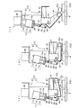
バケット部9の取出し完了後、ロボットハンド部23が、バケット部9を吊持した状態で所定の積込みパレット5(6)上に移動し、下降する(ステップS10)。この取出しから移動および下降の際、角度調整駆動部12における駆動シリンダ13の伸縮ロッド13aが伸張し、作用板15を前記アングルレバー96の上端に作用させて、アングルレバー96を押下げ、バケット本体92を図8(a)のように底部の上向き傾斜角度θを10°程度に維持した傾斜状態とする。このような傾斜状態では、バケット部9の移動中でのワークWの落下を防止することができる。
After the removal of the
図8(a)〜図8(c)は、積込みパレット5(6)内にロボットハンド部23を下降させ、バケット本体92からワークWを積込みパレット5(6)の所定位置に積付ける状態を示しており、積込みパレット5(6)の底部には既に積付けられたワークWが存在する。
8A to 8C show a state in which the
なお、図8(a)〜図8(c)では、衝撃吸収手段10および着脱手段11が省略して示されている。
In FIGS. 8A to 8C, the
ロボットハンド部23を下降させてゆく過程で、渦電流近接スイッチ88が作動すると(ステップS11)、前記制御装置はバケット本体92が何かに衝突したと判断し、その場でロボットハンド部23の下降動作を停止させる(ステップS12)。ここでは、近接スイッチ88によって衝撃検出手段が構成されている。近接スイッチ88は、可動支持板83に近接状態で配置されており、バケット本体92に衝撃が加わった際における衝撃吸収シリンダ81の収縮に伴い、ガイドロッド82とともに可動支持板83が上動して近接スイッチ88から離れると、これを検出信号として出力する。
When the eddy
前記制御装置が近接スイッチ88からの検出信号に応答して衝突であると判断すると、ロボットハンド部23の下降動作を停止させる(ステップS12)。次回の積付け動作までにこの高さが変動する場合があり、そのため、下降位置高さに達する前に既に積付けられているワークWの表面に衝突することも起り得る。このような場合に、ロボットハンド部23の下降動作を停止させるようにロボットコントローラへ停止信号を出力し、これによって、既に積み付けられたワークWへの打痕およびバケット本体92などの損壊を未然に防止することができる。
If the control device determines that a collision has occurred in response to the detection signal from the
ステップS11で、近接スイッチ(バケット衝突検知センサ)88がオンとならない場合、すなわち検出信号がハイレベルからローレベルへ、またはローレベルからハイレベルへ切り換わらない限り、ロボットハンド部23の下降が継続される。ロボットハンド部23の下降位置高さに達すると(ステップS13)、ロボットハンド部23の下降が停止する。図8(a)はこの高さに達してロボットハンド部23の下降が停止した状態を示している。ここでの下降位置高さは、前回積付けられたワークWの表面と、バケット本体92の標準状態における最下端部との間の望ましい高さhに相当し、この高さhはできるだけ小さな値に設定される。
If the proximity switch (bucket collision detection sensor) 88 is not turned on in step S11, that is, unless the detection signal is switched from the high level to the low level or from the low level to the high level, the lowering of the
その後、角度調整駆動部12における駆動シリンダ13がオフ、すなわち、作動圧がかからない状態とされ、これによって作用板15のアングルレバー96に対する押圧作用がなくなり、バケット本体92は、自重によってヒンジピン91を支点としてその先側が下向きに傾動し、図8(b)の仮想線で示されるように、積込みパレット5(6)上のワークWの表面に接する(ステップS14)。
After that, the
前述のようにバケット本体92の自重による傾動の際、バケット本体92の背面の連結ブラケット94およびレバーピン95を介して連結されたアングルレバー96が、長孔97に対する規制ピン98の相対摺動を伴って上動する。アングルレバー96の上動によって、駆動シリンダ13の伸縮ロッド13aの収縮およびガイドロッド14の支持部との摺動を伴い作用板15が押上げられる。アングルレバー96の上端と作用板15の下面とは、当接した状態で、この押上動作や前記押下動作がなされるが、このとき相互の当接面は若干のずれを伴う。このずれは、ローラ99の回転によって抵抗が少なく、円滑に動作させることができる。
As described above, when the
ステップS14で、バケット本体92の先側が積込みパレット5(6)上のワークWの表面に接すると、ロボットハンド部23が上昇を開始する。これに伴い、バケット本体92は、その先側が積込みパレット5(6)上のワークWの表面に接した状態のままヒンジピン91を支点として相対的に傾動し、傾動角度がある角度に達すると、バケット本体92内のワークWが滑り出し(ステップS15)、積込みパレット5(6)上の既に積付けられているワークWの上に積付けられる。図8(c)はこの積付けの状態を示している。
In step S14, when the front side of the
引続きロボットハンド部23の上昇に伴うバケット本体92の自重による相対的な傾動によって、作用板15が押し上げられ、作用板15の側部に付設されたセンサ検知板15a(図5参照)が前記近接スイッチ87に接近する。ステップS16で、近接スイッチ87がセンサ検知板15aを検出すると、制御装置は作用板15が上限位置に達したものと判断し、ロボット装置2はそのときの高さを読み取って記憶する。作用板15の上限位置は、バケット本体92の最大傾斜(全開)角度、たとえば、45°になる場合とされ、この角度で近接スイッチ87が作動するように、前記センサ検知板15aの取付位置が設定される。
Subsequently, the
ステップS16において、読み取ったバケット本体92の高さデータから、次回の下降位置高さhが計算され(ステップS17)、図示しないロボットコントローラに記憶される。この高さhの計算と記憶とは、図7(b)に示すような各エリアAw〜Lw毎になされる。以後、ロボット装置2は、ロボットハンド部23を受渡ステーション3上に移行させかつ下降させ、着脱手段11を作動させて、空になったバケット部9を空いているバケット受台32(33)上にセットする(ステップS18)。ロボット装置2は、さらに、ワークWを収容して待機しているバケット部9を把持し、その後、ステップS7に移行して前述と同様のワークWの移載および積付け動作が繰返される。
In step S16, the next lowered position height h is calculated from the read height data of the bucket body 92 (step S17) and stored in a robot controller (not shown). The calculation and storage of the height h is performed for each area Aw to Lw as shown in FIG. Thereafter, the
このような移載および積付け動作の繰返しは、図7に示すように、予めティーチングされた積付けパターン回数だけ、繰り返し実行される。このとき、各エリアAw〜Lw毎に、前回の各積付け動作時に計算および記憶された前記高さhを基準にして、ロボットハンド部23の下降動作がなされる。
Such transfer and loading operations are repeatedly executed as many times as the number of loading patterns taught in advance, as shown in FIG. At this time, for each of the areas Aw to Lw, the
以上のような構成のロボット装置2においては、バケット本体92が傾動自在とされ、かつその傾斜角度が角度調整駆動手段12によって調整可能とされているから、ワークWの移載および積付け動作において、ロボットハンド部23を垂直状態にして積込みパレット5(6)内に挿入してワークWを移載および積付けすることができる。したがって、ロボットハンド部23が積込みパレット5(6)に干渉することが少なく、積込みパレット5(6)内での動作自由度も大きくなり、効率的な積付けが成される。しかも、ワークWの積付けが、パレット5(6)の底部に、あるいは既に積付けられたワークWがある場合には、その上に接近させた状態で成されるから、ワークWの落下による打痕を少なくすることができる。特に、熱間鍛造品の場合は、被加工面に傷が付くことは製品品質を著しく低下させることになるが、本ロボット装置2によれば、このような懸念も少なくなる。また、ワークWの積付け動作時に次回下降位置高さを計算し、この高さに基づき次回積付け動作がなされるから、ロボットハンド部23の下降時の不意の衝突などが生じにくくなる。しかも、ワークWの積付けは、均一かつ的確に成される。
In the
なお、積込みパレット5,6は、図例では籠形のパレットであることを示しているが、これに限定されず、搬送性機能を備えた他のタイプのパレットであっても良い。また、図7に示した積付けパターンは一例であって、扱うワークWの性状や積込みパレット5,6の大きさ、形状などによって他のパターンが設定されることはいうまでもない。さらに、作業室1のレイアウト構成も、図2の例に限定されるものではない。
Although the
2 物品移載用ロボット装置
3 受渡ステーション
4 ワーク供給コンベア
5,6 積込みパレット
8 バケット保持部
9 バケット部
10 衝撃吸収手段
11 着脱手段
12 角度調整駆動部
20 ロボットベース部
21 ロボットアーム部
23 ロボットハンド部
89 開閉検出スイッチ
W ワーク
DESCRIPTION OF
Claims (6)
ロボットベース部と、前記ロボットベース部に回動自在に連結された多関節ロボットアーム部と、前記ロボットアーム部の先端に回動自在に連結されたロボットハンド部とを含み、
前記ロボットハンド部は、バケット保持部と、前記物品を収容するためのバケット部とからなり、
前記バケット部は、バケット保持部に対して傾動可能に保持され、かつ角度調整駆動部によって傾き角度の調整が可能とされていることを特徴とする物品移載用ロボット装置。 An article transfer robot device for loading an article received from an article supply means at an article delivery station into a predetermined loading container,
A robot base part, an articulated robot arm part rotatably connected to the robot base part, and a robot hand part rotatably connected to a tip of the robot arm part,
The robot hand part is composed of a bucket holding part and a bucket part for accommodating the article,
The article transfer robot apparatus, wherein the bucket part is held so as to be tiltable with respect to the bucket holding part, and an inclination angle can be adjusted by an angle adjustment driving part.
Priority Applications (1)
| Application Number | Priority Date | Filing Date | Title |
|---|---|---|---|
| JP2008195526A JP5139191B2 (en) | 2008-07-29 | 2008-07-29 | Robot equipment for article transfer |
Applications Claiming Priority (1)
| Application Number | Priority Date | Filing Date | Title |
|---|---|---|---|
| JP2008195526A JP5139191B2 (en) | 2008-07-29 | 2008-07-29 | Robot equipment for article transfer |
Publications (2)
| Publication Number | Publication Date |
|---|---|
| JP2010029991A true JP2010029991A (en) | 2010-02-12 |
| JP5139191B2 JP5139191B2 (en) | 2013-02-06 |
Family
ID=41735111
Family Applications (1)
| Application Number | Title | Priority Date | Filing Date |
|---|---|---|---|
| JP2008195526A Expired - Fee Related JP5139191B2 (en) | 2008-07-29 | 2008-07-29 | Robot equipment for article transfer |
Country Status (1)
| Country | Link |
|---|---|
| JP (1) | JP5139191B2 (en) |
Cited By (9)
| Publication number | Priority date | Publication date | Assignee | Title |
|---|---|---|---|---|
| KR101442431B1 (en) * | 2010-07-13 | 2014-09-18 | 니혼 덴산 산쿄 가부시키가이샤 | Industrial robot |
| CN104176511A (en) * | 2014-08-26 | 2014-12-03 | 冯晓龙 | Brick stacking robot |
| CN105773583A (en) * | 2016-05-20 | 2016-07-20 | 合肥工业大学 | Four-station manipulator |
| CN108297110A (en) * | 2018-04-12 | 2018-07-20 | 苏州菱麦自动化设备科技有限公司 | A kind of shooting robot device |
| CN108860834A (en) * | 2018-07-06 | 2018-11-23 | 常熟市中联光电新材料有限责任公司 | Manipulator moves packed set automatically |
| CN109436641A (en) * | 2018-10-18 | 2019-03-08 | 广东利迅达机器人系统股份有限公司 | A kind of plating line carrying loading and unloading system |
| CN112193846A (en) * | 2020-09-27 | 2021-01-08 | 王全明 | Operation is stable and difficult bucket pile up neatly machine people that drops |
| CN112591477A (en) * | 2020-11-11 | 2021-04-02 | 东风汽车集团有限公司 | Method for unstacking differential thick plate stacks |
| WO2021205425A1 (en) * | 2020-04-08 | 2021-10-14 | Prodieco Unlimited Company | Transfer apparatus and a method for transferring product from one level to another level |
Citations (9)
| Publication number | Priority date | Publication date | Assignee | Title |
|---|---|---|---|---|
| JPH0419093A (en) * | 1990-05-14 | 1992-01-23 | Meidensha Corp | Robot collision detecting device |
| JPH0666979U (en) * | 1993-03-08 | 1994-09-20 | 株式会社明電舎 | Hand part shock absorption mechanism for industrial manipulators |
| JPH079542U (en) * | 1993-07-27 | 1995-02-10 | 株式会社阪村機械製作所 | Die-prevention device for forging machine |
| JPH0717491U (en) * | 1993-09-02 | 1995-03-28 | 多摩川精機株式会社 | Robot handling tools |
| JPH07124878A (en) * | 1993-10-29 | 1995-05-16 | Meidensha Corp | Industial manipulator |
| JPH11123492A (en) * | 1997-10-27 | 1999-05-11 | Mitsubishi Materials Corp | Robot hand |
| JP2001105379A (en) * | 1999-10-12 | 2001-04-17 | Smc Corp | Electric hand with buffer function |
| JP2007118175A (en) * | 2005-09-27 | 2007-05-17 | Yaskawa Electric Corp | Conveyance system |
| JP3140032U (en) * | 2007-12-03 | 2008-03-13 | 高津 豊 | Snow removal bucket for forklift |
-
2008
- 2008-07-29 JP JP2008195526A patent/JP5139191B2/en not_active Expired - Fee Related
Patent Citations (9)
| Publication number | Priority date | Publication date | Assignee | Title |
|---|---|---|---|---|
| JPH0419093A (en) * | 1990-05-14 | 1992-01-23 | Meidensha Corp | Robot collision detecting device |
| JPH0666979U (en) * | 1993-03-08 | 1994-09-20 | 株式会社明電舎 | Hand part shock absorption mechanism for industrial manipulators |
| JPH079542U (en) * | 1993-07-27 | 1995-02-10 | 株式会社阪村機械製作所 | Die-prevention device for forging machine |
| JPH0717491U (en) * | 1993-09-02 | 1995-03-28 | 多摩川精機株式会社 | Robot handling tools |
| JPH07124878A (en) * | 1993-10-29 | 1995-05-16 | Meidensha Corp | Industial manipulator |
| JPH11123492A (en) * | 1997-10-27 | 1999-05-11 | Mitsubishi Materials Corp | Robot hand |
| JP2001105379A (en) * | 1999-10-12 | 2001-04-17 | Smc Corp | Electric hand with buffer function |
| JP2007118175A (en) * | 2005-09-27 | 2007-05-17 | Yaskawa Electric Corp | Conveyance system |
| JP3140032U (en) * | 2007-12-03 | 2008-03-13 | 高津 豊 | Snow removal bucket for forklift |
Cited By (10)
| Publication number | Priority date | Publication date | Assignee | Title |
|---|---|---|---|---|
| KR101442431B1 (en) * | 2010-07-13 | 2014-09-18 | 니혼 덴산 산쿄 가부시키가이샤 | Industrial robot |
| CN104176511A (en) * | 2014-08-26 | 2014-12-03 | 冯晓龙 | Brick stacking robot |
| CN105773583A (en) * | 2016-05-20 | 2016-07-20 | 合肥工业大学 | Four-station manipulator |
| CN108297110A (en) * | 2018-04-12 | 2018-07-20 | 苏州菱麦自动化设备科技有限公司 | A kind of shooting robot device |
| CN108297110B (en) * | 2018-04-12 | 2024-05-31 | 苏州菱麦自动化设备科技有限公司 | Shooting manipulator device |
| CN108860834A (en) * | 2018-07-06 | 2018-11-23 | 常熟市中联光电新材料有限责任公司 | Manipulator moves packed set automatically |
| CN109436641A (en) * | 2018-10-18 | 2019-03-08 | 广东利迅达机器人系统股份有限公司 | A kind of plating line carrying loading and unloading system |
| WO2021205425A1 (en) * | 2020-04-08 | 2021-10-14 | Prodieco Unlimited Company | Transfer apparatus and a method for transferring product from one level to another level |
| CN112193846A (en) * | 2020-09-27 | 2021-01-08 | 王全明 | Operation is stable and difficult bucket pile up neatly machine people that drops |
| CN112591477A (en) * | 2020-11-11 | 2021-04-02 | 东风汽车集团有限公司 | Method for unstacking differential thick plate stacks |
Also Published As
| Publication number | Publication date |
|---|---|
| JP5139191B2 (en) | 2013-02-06 |
Similar Documents
| Publication | Publication Date | Title |
|---|---|---|
| JP5139191B2 (en) | Robot equipment for article transfer | |
| KR102115983B1 (en) | Apparatus for automated removal of workpieces arranged in a container | |
| JP5489000B2 (en) | Working device and component picking system | |
| JP7145673B2 (en) | cargo handling equipment | |
| US5419669A (en) | Installation for lining an internal wall of an enclosure with brickwork | |
| US20030040841A1 (en) | Robotic storage buffer system for substrate carrier pods | |
| US20060106487A1 (en) | Programmable load forming system, components thereof, and methods of use | |
| JP6701805B2 (en) | Aligning and transporting device | |
| KR100245531B1 (en) | Frames for the storage of sheets and heavy loads with paravertical orientation in warehouses and horizontal carriage | |
| JP5842846B2 (en) | Machine Tools | |
| JP7401285B2 (en) | automatic warehouse system | |
| CN116809838A (en) | Frame cross beam riveting system and riveting method | |
| WO2014136541A1 (en) | Workpiece carrying method and workpiece carrying system | |
| JPH07187317A (en) | Transfer equipment for ceramic product | |
| JPH079378A (en) | Automatic article handling device | |
| TW202327943A (en) | Stack containment structure | |
| CN113677452B (en) | Workpiece conveying tool, hot pressing device, workpiece conveying method and hot pressing method | |
| JP2021123472A (en) | Retainer | |
| JPS6341719B2 (en) | ||
| JP3529803B2 (en) | Product unloading device for plate processing machine and unloading method using the device | |
| JP2828413B2 (en) | Packing device | |
| CN217291311U (en) | Automatic change system of processing | |
| JPH07251943A (en) | Cargo handling method and device therefor | |
| KR101948876B1 (en) | Pallet Lifting Device | |
| CN218706965U (en) | Outer splint material loading machine |
Legal Events
| Date | Code | Title | Description |
|---|---|---|---|
| A621 | Written request for application examination |
Free format text: JAPANESE INTERMEDIATE CODE: A621 Effective date: 20110713 |
|
| A977 | Report on retrieval |
Free format text: JAPANESE INTERMEDIATE CODE: A971007 Effective date: 20120906 |
|
| A131 | Notification of reasons for refusal |
Free format text: JAPANESE INTERMEDIATE CODE: A131 Effective date: 20120918 |
|
| A521 | Written amendment |
Free format text: JAPANESE INTERMEDIATE CODE: A523 Effective date: 20121001 |
|
| TRDD | Decision of grant or rejection written | ||
| A01 | Written decision to grant a patent or to grant a registration (utility model) |
Free format text: JAPANESE INTERMEDIATE CODE: A01 Effective date: 20121106 |
|
| A01 | Written decision to grant a patent or to grant a registration (utility model) |
Free format text: JAPANESE INTERMEDIATE CODE: A01 |
|
| A61 | First payment of annual fees (during grant procedure) |
Free format text: JAPANESE INTERMEDIATE CODE: A61 Effective date: 20121115 |
|
| R150 | Certificate of patent or registration of utility model |
Free format text: JAPANESE INTERMEDIATE CODE: R150 |
|
| FPAY | Renewal fee payment (event date is renewal date of database) |
Free format text: PAYMENT UNTIL: 20151122 Year of fee payment: 3 |
|
| LAPS | Cancellation because of no payment of annual fees |