JP2010029937A - Hydroforming method and hydroformed component - Google Patents
Hydroforming method and hydroformed component Download PDFInfo
- Publication number
- JP2010029937A JP2010029937A JP2009122181A JP2009122181A JP2010029937A JP 2010029937 A JP2010029937 A JP 2010029937A JP 2009122181 A JP2009122181 A JP 2009122181A JP 2009122181 A JP2009122181 A JP 2009122181A JP 2010029937 A JP2010029937 A JP 2010029937A
- Authority
- JP
- Japan
- Prior art keywords
- metal tube
- shaft
- internal pressure
- pressure
- tube
- Prior art date
- Legal status (The legal status is an assumption and is not a legal conclusion. Google has not performed a legal analysis and makes no representation as to the accuracy of the status listed.)
- Granted
Links
Images


Classifications
-
- B—PERFORMING OPERATIONS; TRANSPORTING
- B21—MECHANICAL METAL-WORKING WITHOUT ESSENTIALLY REMOVING MATERIAL; PUNCHING METAL
- B21D—WORKING OR PROCESSING OF SHEET METAL OR METAL TUBES, RODS OR PROFILES WITHOUT ESSENTIALLY REMOVING MATERIAL; PUNCHING METAL
- B21D26/00—Shaping without cutting otherwise than using rigid devices or tools or yieldable or resilient pads, i.e. applying fluid pressure or magnetic forces
- B21D26/02—Shaping without cutting otherwise than using rigid devices or tools or yieldable or resilient pads, i.e. applying fluid pressure or magnetic forces by applying fluid pressure
- B21D26/033—Deforming tubular bodies
- B21D26/043—Means for controlling the axial pusher
-
- B—PERFORMING OPERATIONS; TRANSPORTING
- B21—MECHANICAL METAL-WORKING WITHOUT ESSENTIALLY REMOVING MATERIAL; PUNCHING METAL
- B21D—WORKING OR PROCESSING OF SHEET METAL OR METAL TUBES, RODS OR PROFILES WITHOUT ESSENTIALLY REMOVING MATERIAL; PUNCHING METAL
- B21D26/00—Shaping without cutting otherwise than using rigid devices or tools or yieldable or resilient pads, i.e. applying fluid pressure or magnetic forces
- B21D26/02—Shaping without cutting otherwise than using rigid devices or tools or yieldable or resilient pads, i.e. applying fluid pressure or magnetic forces by applying fluid pressure
- B21D26/033—Deforming tubular bodies
- B21D26/037—Forming branched tubes
-
- B—PERFORMING OPERATIONS; TRANSPORTING
- B21—MECHANICAL METAL-WORKING WITHOUT ESSENTIALLY REMOVING MATERIAL; PUNCHING METAL
- B21D—WORKING OR PROCESSING OF SHEET METAL OR METAL TUBES, RODS OR PROFILES WITHOUT ESSENTIALLY REMOVING MATERIAL; PUNCHING METAL
- B21D26/00—Shaping without cutting otherwise than using rigid devices or tools or yieldable or resilient pads, i.e. applying fluid pressure or magnetic forces
- B21D26/02—Shaping without cutting otherwise than using rigid devices or tools or yieldable or resilient pads, i.e. applying fluid pressure or magnetic forces by applying fluid pressure
- B21D26/033—Deforming tubular bodies
- B21D26/041—Means for controlling fluid parameters, e.g. pressure or temperature
-
- Y—GENERAL TAGGING OF NEW TECHNOLOGICAL DEVELOPMENTS; GENERAL TAGGING OF CROSS-SECTIONAL TECHNOLOGIES SPANNING OVER SEVERAL SECTIONS OF THE IPC; TECHNICAL SUBJECTS COVERED BY FORMER USPC CROSS-REFERENCE ART COLLECTIONS [XRACs] AND DIGESTS
- Y10—TECHNICAL SUBJECTS COVERED BY FORMER USPC
- Y10T—TECHNICAL SUBJECTS COVERED BY FORMER US CLASSIFICATION
- Y10T29/00—Metal working
- Y10T29/49—Method of mechanical manufacture
- Y10T29/49805—Shaping by direct application of fluent pressure
-
- Y—GENERAL TAGGING OF NEW TECHNOLOGICAL DEVELOPMENTS; GENERAL TAGGING OF CROSS-SECTIONAL TECHNOLOGIES SPANNING OVER SEVERAL SECTIONS OF THE IPC; TECHNICAL SUBJECTS COVERED BY FORMER USPC CROSS-REFERENCE ART COLLECTIONS [XRACs] AND DIGESTS
- Y10—TECHNICAL SUBJECTS COVERED BY FORMER USPC
- Y10T—TECHNICAL SUBJECTS COVERED BY FORMER US CLASSIFICATION
- Y10T428/00—Stock material or miscellaneous articles
- Y10T428/12—All metal or with adjacent metals
- Y10T428/1241—Nonplanar uniform thickness or nonlinear uniform diameter [e.g., L-shape]
Abstract
Description
本発明は、金属管を金型に入れ、当該金型を型締めした後、管内に内圧と管軸方向の押し込み(以後、軸押しと称す)を負荷することにより所定形状に加工するハイドロフォーム加工方法、及びそれにより加工されたハイドロフォーム加工品に関する。 The present invention is a hydroform that is processed into a predetermined shape by placing a metal tube in a mold, clamping the mold, and then applying internal pressure and pushing in the axial direction of the pipe (hereinafter referred to as axial pushing) into the pipe. The present invention relates to a processing method and a hydroform processed product processed by the processing method.
近年ハイドロフォーム加工は自動車部品分野を中心に適用が拡大されている。ハイドロフォーム加工の利点としては、従来複数個のプレス加工品で構成されていた自動車部品を1本の金属管から加工できるという部品統合によるコストダウンのほか、溶接箇所が減ることによる軽量化などが挙げられる。しかし、素材となる金属管は一般的に一様断面であるため、拡管率(素管の周長に対するハイドロフォーム加工後の周長の比)の大きな形状は加工困難であった。 In recent years, application of hydroforming has been expanded mainly in the field of automobile parts. Advantages of hydroforming include the cost reduction by integrating parts that can be processed from a single metal tube, and the weight reduction by reducing the number of welding points. Can be mentioned. However, since the metal tube used as a raw material generally has a uniform cross section, it is difficult to process a shape having a large tube expansion ratio (ratio of the peripheral length after hydroforming to the peripheral length of the raw tube).
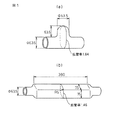
また、ハイドロフォーム加工の難しさは拡管率だけで決まらず、断面形状や曲げの有無等にも影響されるが、特に拡管する箇所の長さの影響は大きい。例えば、図1(a)のようなT成形では、拡管する長さが短いため1.6以上の大拡管率でも容易に加工できる。それに対して図1(b)のような拡管する箇所が長い形状では、それほど拡管率が大きくなくても加工が難しい。 Moreover, the difficulty of hydroforming is not determined only by the expansion ratio, but is also affected by the cross-sectional shape and the presence / absence of bending, but the influence of the length of the expanded portion is particularly large. For example, in the T molding as shown in FIG. 1 (a), since the length of pipe expansion is short, it can be easily processed even with a large pipe expansion ratio of 1.6 or more. On the other hand, in the shape where the portion to be expanded is long as shown in FIG. 1B, the processing is difficult even if the expansion rate is not so large.
拡管する箇所の長いハイドロフォーム加工では、多くの軸押しを負荷しないと管の肉厚が薄くなり割れてしまうが、軸押し量が多い分、管軸方向の座屈やしわが生じやすい。さらに、拡管する箇所が長いということは、その領域では初期状態で金属管と金型が未接触であることを意味するため、より座屈やしわが生じやすくなる。
本発明者らが知る限りでは、拡管率が1.35以上の領域が元の金属管外径の3.5倍以上あるハイドロフォーム加工品は見受けられない。
In the hydroforming process where the portion to be expanded is long, if a large amount of axial pressing is not applied, the thickness of the tube becomes thin and cracks. Furthermore, the fact that the portion where the tube is expanded is long means that the metal tube and the mold are not in contact with each other in the initial state, so that buckling and wrinkling are more likely to occur.
As far as the present inventors know, there is no hydroform processed product in which the area where the tube expansion ratio is 1.35 or more is 3.5 times or more the original outer diameter of the metal tube.
一般に、ハイドロフォーム加工で座屈やしわを防止するためには、内圧と軸押しの負荷経路(以後、単に負荷経路と称す)を試行錯誤して適切な負荷経路を求めることが重要である。
負荷経路の一般的な例を図2に示す。まず内圧のみを昇圧する工程1(管端をシールするために微小な軸押しを伴う場合もある)、内圧と軸押しを折れ線状に負荷する工程2、コーナーをシャープに加工するために内圧のみを昇圧する工程3(コーナーのない形状では省略する場合もある、また管端のシールを確保するために微小な軸押しを伴う場合もある)で構成される。
In general, in order to prevent buckling and wrinkles in hydroforming, it is important to obtain an appropriate load path by trial and error of an internal pressure and a load path of axial pushing (hereinafter simply referred to as a load path).
A typical example of the load path is shown in FIG. First, only the internal pressure is increased in step 1 (there may be a small axial push to seal the pipe end), the internal pressure and axial push are loaded in a polygonal line, and only the internal pressure is applied to sharpen the corner. Is boosted in step 3 (may be omitted for shapes without corners, or may be accompanied by a minute axial push to ensure a seal at the tube end).
このうち工程2の適切な経路を求めるのに一番労力が費やされ、ハイドロフォーム技術者の熟練に依るところが大きい。特許文献1に、その一例が紹介されているが、当該方法は予め割れ限界線としわ限界線を作成しておき、その両限界線の間で負荷経路を選択する方法である。しかし実際には、この両限界線を作成することが難しく、通常、多くの実験や数値解析の試行錯誤が必要になる。また、限界線自体が折れ線状になる場合も多く、そうなるとその折れ線を決定するための変数が多くなるため試行錯誤に多大な労力が必要とされる。
Of these, the most labor is expended to find an appropriate route for the
また、特許文献2には軸押しに伴って内圧を周期的に変動させる方法が提示されている。例えば、図3に示すような矩形波(a)や正弦波(b)のように内圧を変動させる方法である。当該方法は割れを防止する方法として提唱されているが、その後の研究では、しわの抑制にも効果があると報告されている(非特許文献1参照)。しかし、当該方法の負荷経路は上述の折れ線状の負荷経路における変数に対して、波形・周期・振れ幅などの変数が増加するため適正な負荷経路を求めることはさらに難しくなる。
拡管する領域の長い形状をハイドロフォームする場合の方法としては、上記のような負荷経路による方法以外に、金型で工夫する方法もある。例えば特許文献3では可動金型とカウンターを併用することで金属管の座屈を防止しながら長い領域の拡管を実現している。しかし、当該方法の金型構造は非常に複雑であるため金型費用が高くなる。さらに、加工中の制御項目が内圧と軸押し(可動金型による軸押し)だけでなくカウンターの後退位置も制御可能な設備も必要となる。また制御する項目が増加するため、適切な負荷経路を求めるために、より熟練や試行錯誤が必要となる。
As a method for hydroforming a long shape of a region to be expanded, there is a method of devising with a mold other than the method using the load path as described above. For example, in
本発明では、拡管する領域の長いハイドロフォーム加工品を座屈やしわが残存することなく加工できる加工方法、しかも熟練や試行錯誤を極力必要としない加工方法を提案する。また当該加工方法で加工したハイドロフォーム加工品も提案する。 The present invention proposes a processing method that can process a hydroformed product having a long expansion area without buckling or wrinkling, and a processing method that requires as little skill and trial and error as possible. We also propose hydroformed products processed by this processing method.
係る課題を解決するため、本発明の要旨とするところは下記の通りである。
(1)金属管内部に圧力媒体を供給して内圧を負荷し、前記金属管の両端から軸押しをして前記金属管を所定形状に成形するハイドロフォーム加工方法において、前記金属管の両端の位置を固定した状態、または全軸押し量の10%以下の軸押しをした状態で内圧を昇圧させ、次いで、内圧を一定圧力に保持しながら軸押しをすることにより、前記金属管の端部近傍を拡管させる第1の工程を実施した後、軸押しをせずに内圧のみ昇圧させることにより前記金属管の中央部を拡管させる第2の工程を実施し、その後、軸押しをせずに内圧のみを前記一定圧力の値まで下げる第3の工程を実施した後、前記第1から第3の工程を1回または複数回繰り返した後に、軸押しをしないで又は全軸押し量の10%以下の軸押しをした状態で内圧を昇圧させることを特徴とするハイドロフォーム加工方法。
(2)金属管内部に圧力媒体を供給して内圧を負荷し、前記金属管の両端から軸押しをすると同時に可動金型を軸押しして前記金属管を所定形状に成形するハイドロフォーム加工方法において、前記金属管の両端及び可動金型の位置を固定した状態、または全軸押し量の10%以下の軸押しをした状態で内圧を昇圧させ、次いで、内圧を一定圧力に保持しながら前記金属管の両端と可動金型を同時に軸押しをすることにより、前記金属管の端部近傍を拡管させる第1の工程を実施した後、前記金属管の両端の軸押し及び可動金型の軸押しをせずに内圧のみ昇圧させることにより前記金属管の中央部を拡管させる第2の工程を実施し、その後、前記金属管の両端の軸押し及び可動金型の軸押しをせずに内圧のみを前記一定圧力の値まで下げる第3の工程を実施した後、前記第1から第3の工程を1回または複数回繰り返した後に、軸押しをしないで又は全軸押し量の10%以下の軸押しをした状態で内圧を昇圧させることを特徴とするハイドロフォーム加工方法。
(3)前記(1)又は(2)記載のハイドロフォーム加工方法を用いて製造した加工品であって、前記金属管の拡管される断面の周長が金属素管の断面の周長に対し1.35倍以上拡管されている領域が、前記金属管の管軸方向に前記金属素管の外径の3.5倍以上連続していることを特徴とするハイドロフォーム加工品。
In order to solve the problem, the gist of the present invention is as follows.
(1) In a hydroforming method in which a pressure medium is supplied to the inside of a metal tube to apply an internal pressure, and the metal tube is formed into a predetermined shape by axially pushing from both ends of the metal tube, By increasing the internal pressure in a state where the position is fixed or in a state where the shaft is pressed at 10% or less of the total shaft pressing amount, and then pressing the shaft while maintaining the internal pressure at a constant pressure, the end of the metal tube After performing the first step of expanding the vicinity, the second step of expanding the central portion of the metal tube by increasing only the internal pressure without pressing the shaft is performed, and then without pressing the shaft. After performing the third step of reducing only the internal pressure to the value of the constant pressure, after repeating the first to third steps one or more times, do not push the shaft or 10% of the total push amount The internal pressure is increased with the following shaft push Hydroform processing method characterized by the above.
(2) Hydroform processing method of supplying a pressure medium to the inside of a metal tube, applying an internal pressure, axially pushing from both ends of the metal tube and simultaneously pushing a movable mold to form the metal tube into a predetermined shape The internal pressure is increased in a state where both ends of the metal tube and the movable mold are fixed, or in a state where the axial pressing is 10% or less of the total axial pressing amount, and then the internal pressure is maintained at a constant pressure. After carrying out the first step of expanding the vicinity of the end of the metal tube by simultaneously pressing both ends of the metal tube and the movable mold, the axial push of the both ends of the metal tube and the axis of the movable mold The second step of expanding the central portion of the metal tube by increasing only the internal pressure without pushing is performed, and then the internal pressure without pushing the shaft at both ends of the metal tube and the shaft of the movable mold. 3 to lower only to the constant pressure value After carrying out step (1), the first to third steps are repeated once or a plurality of times, and then the internal pressure is increased without pushing the shaft or with a shaft push of 10% or less of the total shaft push amount. Hydroform processing method characterized by the above.
(3) A processed product manufactured using the hydroform processing method according to (1) or (2), wherein the circumference of the cross-section of the metal pipe expanded relative to the cross-section of the
なお、本発明で金属管の端部近傍とは、内圧一定で軸押しをする前の金属管の長さに対し、金属管の端部から35%以内の領域と定義する。また、圧力媒体としては、液体、気体または固体であっても、ゴム、低融点金属、鋼玉など圧力を伝達可能なものを全て含む。 In the present invention, the vicinity of the end portion of the metal tube is defined as a region within 35% from the end portion of the metal tube with respect to the length of the metal tube before the axial push with a constant internal pressure. The pressure medium includes all materials capable of transmitting pressure, such as rubber, low-melting-point metal, and steel balls, even if they are liquid, gas, or solid.
本発明によって、拡管する領域の長い形状のハイドロフォーム加工が容易になる。これによって、ハイドロフォーム加工品の適用範囲が拡大され、部品統合や軽量化が実現できる。特に自動車部品への適用は、車両の軽量化が進むことで燃費が向上し、その結果、地球温暖化の抑制に貢献できる。また、これまで適用が進んでいなかった産業分野、例えば、家電製品、家具、建機部品、二輪部品、建築部材等への広がりも期待できる。 According to the present invention, it is possible to easily process a hydroform having a long shape of a region to be expanded. As a result, the application range of hydroformed products is expanded, and component integration and weight reduction can be realized. In particular, application to automobile parts can improve fuel efficiency by reducing the weight of the vehicle and, as a result, can contribute to the suppression of global warming. In addition, it can be expected to spread to industrial fields that have not been applied so far, for example, home appliances, furniture, construction machinery parts, two-wheeled parts, and building members.
図4(a)、(b)は、ハイドロフォーム金型2、3内にセットされた円形断面の金属管1を、ハイドロフォーム加工により拡管して長方形断面を有するハイドロフォーム加工品4に成形する例を示している。例えば、外径63.5mm、肉厚2.0mmの鋼管(鋼種:JIS規格STKM13B)を63.5mm×84mm(コーナーR=10mm)の長方形断面に拡管する。この場合の拡管率は、1.39である。また拡管率1.39の領域の長さは320mm(外径63.5mmの5倍)である。
以下、当該ハイドロフォーム金型による加工を例にして、本発明の実施の形態を図5に示す負荷経路及び図6に示す変形の推移に沿って説明する。
4 (a) and 4 (b), the
In the following, an embodiment of the present invention will be described along the load path shown in FIG. 5 and the transition of deformation shown in FIG.
まず、工程1では従来方法と同様に軸押しを負荷しないで、金属管1の内部に圧力媒体(例えば水)6を供給して内圧のみ昇圧する。ただし、場合によっては管端からのシール漏れを防ぐために全軸押し量の10%以下の微小な軸押しをする場合がある。この初期圧力PH(MPa)は、金属管が割れることなく塑性変形される圧力であり、計算や実験で比較的容易に求められる。
First, in
例えば、発明者らが研究した結果、金属管の平面歪状態における降伏開始圧力Pp(下式(1)参照)を初期圧力PHの目安にできることが分かっている(非特許文献2参照)。なお、式中のDは素管の外径(mm)、tは肉厚(mm)、rはr値を示し、YSおよびYSpは単軸引張状態および平面歪状態の0.2%耐力をそれぞれ示している。 For example, the results which we have studied, have been found to be started breakdown in the plane strain state of the metal pipe pressure Pp (the following formula (1) refer) to measure the initial pressure P H (see Non-Patent Document 2). In the formula, D is the outer diameter (mm) of the raw tube, t is the thickness (mm), r is the r value, and YS and YSp are the 0.2% proof stress in the uniaxial tension state and the plane strain state. Each is shown.

ただし、形状が複雑な場合などは上式との誤差が大きくなるので、初期圧力PHは実験的に求める方が確実である。具体的には、軸押しを負荷せずに金属管が割れるまで内圧を昇圧させて割れたときの圧力を参考に初期圧力PHを定める。例えば、割れた時の圧力の0.7〜0.8倍の圧力などに設定する。 However, since the error from the above equation becomes large when the shape is complicated, the initial pressure PH is more surely obtained experimentally. Specifically, the initial pressure PH is determined with reference to the pressure when the internal pressure is increased until the metal tube breaks without applying a shaft push, and the pressure when cracked. For example, the pressure is set to 0.7 to 0.8 times the pressure at the time of cracking.
以上のように、計算あるいは実験で求めた初期圧力PHまで内圧を昇圧するが、この状態は図5では状態1に相当する。発明者らの研究の結果、軸押しなしで圧力のみ昇圧した状態1の時点では、金属管は中央部(図6の状態1のM部)で最も拡管される。
As described above, the internal pressure is increased to the initial pressure PH obtained by calculation or experiment. This state corresponds to
次に、内圧と軸押しが負荷される工程2に入る。この工程2では、軸押しと昇圧を交互に繰り返す。まず内圧を初期圧力PHに保持したまま軸押しパンチ5を進行させて軸押しのみ負荷する。この工程を図5の負荷経路拡大図に示すように第1の工程と呼ぶ。発明者らの研究の結果、内圧を昇圧しない軸押しのみの負荷でも金属管は拡管されるが、この場合は中央部からではなく端部近傍(図6の状態2のN1部)で拡管が進行する。この端部近傍からの拡管がハイドロフォーム加工における座屈やしわの要因となる。この座屈やしわの程度は軸押し中の内圧の昇圧によって、ある程度は緩和できるが、完全には解消されない。しかも内圧を高め過ぎると割れの危険性が高まる。よって、適正な内圧と軸押しの負荷経路を求めるためには、多大な試行錯誤や熟練が必要とされる。それに対して、この方法では内圧の値は保持したままであるため、軸押し中の拡管では割れる可能性はほとんどない。しかも負荷経路の変数も軸押し量だけのため非常に単純である。
Next, the
状態2までの軸押し量δS(mm)は、その後の工程でしわが解消しうる程度の軸押し量に抑える必要がある。適正な軸押し量δSの求め方としては、軸押し量を変えた途中止めサンプルを採取して、大きなしわにならない程度の軸押し量を選択すればよい。この適正な軸押し量δSの値は、加工形状や素管の寸法・強度によって異なるが、発明者らの研究結果から、およそ素管肉厚の2〜4倍が好ましく、更に3倍程度が好適である。
The shaft pressing amount δ S (mm) up to the
次に、軸押しを停止させて内圧のみ昇圧する。この工程を第2の工程と呼ぶ。この工程では軸押しを負荷していないため拡管は再び中央部(図6の状態3のM部)で進行する。すると、状態3では管軸方向に一様な拡管形状に近づき、座屈やしわの進行が抑制される。この昇圧時の最大ピーク圧力PT(MPa)は、金属管が割れないぎりぎりの圧力が望ましい。すなわち、前述の初期圧力PHを求めた際の軸押しなしで割れる圧力より若干低い圧力、例えば割れる圧力の0.90〜0.99倍が好ましく、更に0.95倍程度に設定することが好適である。
Next, the shaft push is stopped and only the internal pressure is increased. This process is called a second process. In this process, since the axial push is not loaded, the expansion of the tube proceeds again in the central portion (M portion in
この後、軸押しを停止したまま一旦圧力を初期圧力PHまで低下させる。この工程を第3の工程と呼ぶ。仮に、内圧を下げずに圧力PTのまま軸押しを負荷する階段状の負荷経路にすると、圧力が高過ぎるため金属管はすぐに割れてしまう。よってピーク圧力PTまで昇圧した後に一旦初期圧力PHまで低下させる第3の工程が、本発明方法では非常に重要な意味を持つ。 Thereafter, once while stopped axial pressing to reduce the pressure to the initial pressure P H. This step is called a third step. If a step-like load path is used to load the shaft while maintaining the pressure PT without reducing the internal pressure, the metal tube will break immediately because the pressure is too high. Therefore, the third step of increasing the pressure to the peak pressure P T and then decreasing it to the initial pressure P H is very important in the method of the present invention.
以上のような、第1の工程から第3の工程を同様に繰り返すと、中央部と端部近傍が交互に拡管されて、管軸方向に均一な拡管形状となる。また、図7のようにN1部の内側にN2部のような拡管部が複数現れる場合もある。しかし、本発明方法の基本的な効果は変わらず、管軸方向に一様な拡管形状が得られる。 When the first to third steps as described above are repeated in the same manner, the central portion and the vicinity of the end portion are alternately expanded to form a uniform expanded shape in the tube axis direction. Further, as shown in FIG. 7, there may be a case where a plurality of expanded portions such as the N2 portion appear inside the N1 portion. However, the basic effect of the method of the present invention is not changed, and a uniform expanded pipe shape can be obtained in the tube axis direction.
以上の第1から第3の工程を1回または複数回繰り返すと、最後は図8のように管軸方向に渡ってほぼ全長で金型に接触する。この状態になると金型拘束により割れが起き難くなるため軸押しを停止したまま内圧のみを昇圧する工程3を行い、詳細形状やシャープなコーナーRを加工する。但し、場合によっては管端からのシール漏れを防ぐために全軸押し量の10%以下の微小な軸押しをしながら、内圧を昇圧してもよい。
When the above first to third steps are repeated once or a plurality of times, the final step is to contact the mold over almost the entire length in the tube axis direction as shown in FIG. In this state, cracks are less likely to occur due to die restraint, so that
以上が、前記(1)で提唱したハイドロフォーム加工方法の実施の態様の説明であるが、この方法を可動金型を用いたハイドロフォーム加工に適用したのが、前記(2)で提唱した方法である。
以下、その方法の実施の態様を説明する。
The above is the description of the embodiment of the hydroform processing method proposed in the above (1). The method proposed in the above (2) is applied to the hydroform processing using a movable mold. It is.
Hereinafter, embodiments of the method will be described.
この方法では、図9に示すように、固定金型7、8と可動金型9よりなるハイドロフォーム金型を使用する。可動金型9は、固定金型7、8の長方形断面の型内を移動できるようになっており、金属管1の両端を軸押しする際、可動金型も同時に軸押しされ、拡管された部分を可動金型によって同時に押し込むことができる。
In this method, as shown in FIG. 9, a hydroform mold comprising fixed
この可動金型9を用いる場合でも、管端のみを軸押しする場合と同様に、図5を用いて説明した負荷経路を用いて実施できる。
図9(a)のようにセットされた金属管に対し、金属管1の両端及び可動金型9の位置を固定した状態、または全軸押し量の10%以下の軸押しをした状態で内圧を昇圧させる工程1を実施する。次に、工程2では、まず、内圧を一定圧力に保持しながら金属管1の両端と可動金型9を同時に軸押しすることにより、金属管1の端部近傍を拡管させる第1の工程を実施し、続いて、内圧のみ昇圧させることにより金属管1の中央部を拡管させる第2の工程を実施し、その後、内圧を前記一定圧力の値まで下げる第3の工程を実施する。そして、この第1から第3の工程を1回または複数回繰り返してほぼ製品形状に加工した後に、軸押しをしないで又は全軸押し量の10%以下の軸押しをした状態で内圧を昇圧させて、図9(b)のようなハイドロフォーム加工品4を得る。
Even when this
Internal pressure in a state where both ends of the
この可動金型を用いた方法は、管端だけを押す方法と比べて拡管しない部分の摩擦抵抗を削減することができるため大きな拡管率が達成できる。しかし、この方法では、加工開始初期の時点において最終的に得たい加工品の形状よりも長い拡管領域が存在するため、従来は、管軸方向の座屈やしわの発生が通常のハイドロフォーム加工よりも起こりやすいという問題があった。
これに対し、前記説明したような負荷経路を用いることにより、可動金型を用いた場合でも前記の座屈やしわの問題が解消できるので、さらに大きな効果を発揮できる。
Since the method using this movable mold can reduce the frictional resistance of the portion where the tube is not expanded compared with the method of pushing only the tube end, a large tube expansion rate can be achieved. However, with this method, there is a tube expansion area that is longer than the shape of the workpiece that is ultimately desired at the beginning of machining, and so conventionally, the occurrence of buckling and wrinkling in the tube axis direction is normal hydroforming. There was a problem that it was more likely to occur.
On the other hand, by using the load path as described above, even when a movable mold is used, the above-described buckling and wrinkle problems can be solved, so that a greater effect can be exhibited.
以上のような一連のハイドロフォーム加工方法(通常のハイドロフォーム加工方法および可動金型を用いたハイドロフォーム加工方法)を用いると管軸方向に長い部品でも座屈やしわが残存しないで、かつ、拡管率の大きな加工品を得ることができる。具体的には従来の方法では加工不可能であった拡管率1.35以上の領域が管軸方向に素管径の3.5倍以上連続して存在するハイドロフォーム加工品を得ることができる。ただし、上記では、拡管率1.35以上の領域の長さが極端に長い、素管径の5倍の例で説明した。 When a series of hydroforming processes as described above (normal hydroforming process and hydroforming process using a movable mold) are used, no buckling or wrinkles remain even in parts that are long in the tube axis direction, and A processed product with a large expansion rate can be obtained. Specifically, it is possible to obtain a hydroformed product in which a region having a tube expansion ratio of 1.35 or more, which was impossible to process by the conventional method, continuously exists in the tube axis direction by 3.5 times or more of the raw tube diameter. . However, in the above description, an example in which the length of the region where the tube expansion ratio is 1.35 or more is extremely long, which is five times the diameter of the raw tube, has been described.
下記に本発明の実施例を示す。 Examples of the present invention are shown below.
(実施例1)
素管には外径63.5mm、肉厚2.0mm、長さ600mmの鋼管(鋼種:JIS規格STKM13B)を用いた。材料特性は、YSが385MPa、r値が0.9である。ハイドロフォーム金型は、前述の図4の金型を用いた。圧力媒体として、水を用いた。
Example 1
A steel pipe (steel type: JIS standard STKM13B) having an outer diameter of 63.5 mm, a wall thickness of 2.0 mm, and a length of 600 mm was used as the base pipe. The material properties are YS of 385 MPa and r value of 0.9. As the hydroform mold, the mold shown in FIG. 4 was used. Water was used as the pressure medium.
ハイドロフォームの負荷経路を図10に示すが、当該負荷経路は以下の手順で決定した。まず前述の式(1)より平面歪状態における降伏開始圧力Ppを計算すると28.4MPaであった。しかし、実際に軸押しなしで当該鋼管が割れるまで内圧を昇圧したところ26.5MPaで割れた。よって、初期圧力PHは、実際に割れた圧力26.5MPaの0.76倍の20MPaに設定し、最大ピーク圧力PTは26.5MPaの0.96倍の25.5MPaに設定した。次に、1サイクル当たりの軸押し量δSは、素管肉厚2mmの3倍の6mmに設定した。そこで初期圧力PH:20MPa、最大ピーク圧力PT:25.5MPa、軸押し量δS:6mmのサイクルを複数回実施する試験を行ったところ、10サイクルでほぼ全長に渡って金型と接触した。そこで、トータル10サイクル、すなわち最終軸押し量60mmまで繰り返した後、軸押しを停止させて内圧のみ高圧に負荷した。最終圧力はコーナーの曲率半径Rが金型と同様のR=10mmになる十分な圧力として135MPaに設定した。
The load path of the hydroform is shown in FIG. 10, and the load path was determined by the following procedure. First, the yield start pressure Pp in the plane strain state was calculated from the above-mentioned formula (1), and it was 28.4 MPa. However, when the internal pressure was increased until the steel pipe broke without actually pushing the shaft, it cracked at 26.5 MPa. Therefore, the initial pressure PH was set to 20 MPa, 0.76 times the actual cracking pressure of 26.5 MPa, and the maximum peak pressure PT was set to 25.5 MPa, 0.96 times 26.5 MPa. Next, the axial push amount δS per cycle was set to 6 mm, which is three times the
以上のような手順で図10に示すような適正な負荷経路が決定し、座屈やしわ等の加工不良のないハイドロフォーム加工品が得られた。なお、従来のような折れ線型の負荷経路で適正な負荷経路を求めようとしたら、トータル50回の試行錯誤を繰り返しても加工品の座屈やしわが解消されなかった。一方、本発明による負荷経路では、トータル3本の試行錯誤をした後、4本目で図10のような適正な負荷経路を得ることができた。 An appropriate load path as shown in FIG. 10 was determined by the procedure as described above, and a hydrofoam processed product free from processing defects such as buckling and wrinkling was obtained. In addition, when trying to obtain an appropriate load path with a conventional broken line type load path, buckling and wrinkles of the workpiece were not eliminated even after a total of 50 trials and errors. On the other hand, in the load route according to the present invention, after a total of three trials and errors, an appropriate load route as shown in FIG.
本発明によって得られたハイドロフォーム加工品では、長方形に拡管されている断面の周長が278mmあり、これは63.5φの素管の1.39倍の拡管率に当たる。しかも、当該拡管率を有する断面の管軸方向の長さは、素管外径63.5mmの5.0倍の320mmある。このように、従来のハイドロフォーム加工方法では不可能であった大拡管率で、かつ、長尺のハイドロフォーム加工品を本発明方法で得ることができた。 In the hydrofoam processed product obtained by the present invention, the circumference of the cross section expanded into a rectangle is 278 mm, which corresponds to a tube expansion ratio 1.39 times that of a 63.5φ base tube. Moreover, the length in the tube axis direction of the cross section having the tube expansion ratio is 320 mm, which is 5.0 times the raw tube outer diameter of 63.5 mm. In this way, a long hydrofoam processed product having a large pipe expansion rate that was impossible with the conventional hydrofoam processing method could be obtained by the method of the present invention.
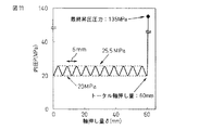
また比較のため前述の特許文献2に記載されている周期的に変動させる負荷経路でもハイドロフォーム加工を試みた。負荷経路を図11に示す。周期の波形は、本発明方法の初期圧力PH:20MPa、最大ピーク圧力PT:25.5MPa、軸押し量δS:6mmのサイクルと合わせて、波形の低圧側頂点圧力を20MPa、高圧側頂点圧力を25.5MPa、波長を6mmの正弦波とした。サイクル数も10サイクルと同一にして最終的に60mmまで軸押した後、135MPaまで昇圧する負荷経路とした。
For comparison, hydroforming was also attempted on a load path that is periodically changed in
しかし実際にハイドロフォーム加工をすると1サイクル目ですぐに割れてしまった。本発明方法と異なり、軸押し中の圧力が高いためと思われる。念のため圧力を全体的に3MPa下げて同様の加工を行ったところ、割れは防止できたが、加工終了後に大きなしわが残った。本発明方法と異なり、サイクル内で昇圧する際に軸押しが伴うためしわが発生しやすかったと思われる。 However, when it was actually hydroformed, it broke immediately after the first cycle. Unlike the method of the present invention, it seems that the pressure during shaft pushing is high. As a precaution, when the same processing was performed with the pressure lowered as a whole, cracks could be prevented, but large wrinkles remained after the processing was completed. Unlike the method of the present invention, it seems that wrinkles were likely to occur because the shaft was pushed when the pressure was increased in the cycle.
(実施例2)
実施例1と同一の素管を用いて、図9に示す可動金型を用いたハイドロフォーム金型で実施例1と同一形状のハイドロフォーム加工品の加工を試みた。最終的な加工形状における拡管部の長さは320mmを実現するため、加工初期の可動型の位置は予め60mm後退した位置からスタートさせた。それ以外は、実施例1と全く同一の図10の負荷経路で加工を行った。圧力媒体として、水を用いた。
その結果、本発明によって得られたハイドロフォーム加工品では、長方形に拡管されている断面の周長が278mmあり、これは63.5φの素管の1.39倍の拡管率に当たる。しかも、当該拡管率を有する断面の管軸方向の長さは、素管外径63.5mmの5.0倍の320mmあり、実施例1と同様に、座屈やしわ等の加工不良のない加工品が得られた。しかも実施例2は、実施例1の負荷経路をそのまま利用できたため、試行錯誤は一切不要であった。
(Example 2)
Using the same raw tube as in Example 1, an attempt was made to process a hydroformed product having the same shape as in Example 1 with a hydroform mold using the movable mold shown in FIG. In order to realize the length of the expanded portion in the final processed shape as 320 mm, the position of the movable mold at the initial stage of processing was started from a position retracted by 60 mm in advance. Other than that, the machining was performed in the same load path as in FIG. Water was used as the pressure medium.
As a result, in the hydrofoam processed product obtained by the present invention, the circumference of the cross section expanded into a rectangular shape is 278 mm, which corresponds to a tube expansion rate of 1.39 times that of a 63.5φ base tube. Moreover, the length in the tube axis direction of the section having the tube expansion ratio is 320 mm, which is 5.0 times the outer diameter of the raw tube 63.5 mm, and there is no processing defect such as buckling or wrinkle as in the first embodiment. A processed product was obtained. Moreover, since the load path of the first embodiment can be used as it is in the second embodiment, no trial and error is necessary.
(実施例3)
実施例1と同一の金属管と同一の金型を用いて、図12に示す負荷経路でハイドロフォーム加工を実施した。当該負荷経路は図10の負荷経路と異なり、初期圧力を上げる際の管端シール性を上げるために微小な軸押し量3mm押し込んだ。更に、最終昇圧する際の管端シール性を上げるために微小な軸押し量3mm押し込んだ。その間の負荷経路は図10の場合と基本的に同じとしたが、トータルの軸押し量を60mmと同じにするため、サイクル数は1回減らした。圧力媒体として、水を用いた。
その結果、本発明によって得られたハイドロフォーム加工品では、長方形に拡管されている断面の周長が278mmあり、これは63.5φの素管の1.39倍の拡管率に当たる。しかも、当該拡管率を有する断面の管軸方向の長さは、素管外径63.5mmの5.0倍の320mmあり、当該負荷経路を用いても、実施例1と同様に、大拡管率で、かつ、長尺のハイドロフォーム加工品を本発明方法で得ることができた。
(Example 3)
Using the same metal tube and the same metal mold as in Example 1, hydroforming was performed in the load path shown in FIG. The load path is different from the load path of FIG. 10, and a small axial push amount of 3 mm was pushed in to improve the tube end sealability when raising the initial pressure. Furthermore, in order to improve the tube end sealability at the time of final pressure increase, a small axial push amount of 3 mm was pushed in. The load path in the meantime was basically the same as in FIG. 10, but the number of cycles was reduced once to make the total axial push amount the same as 60 mm. Water was used as the pressure medium.
As a result, in the hydrofoam processed product obtained by the present invention, the circumference of the cross section expanded into a rectangular shape is 278 mm, which corresponds to a tube expansion rate of 1.39 times that of a 63.5φ base tube. Moreover, the length in the tube axis direction of the section having the tube expansion ratio is 320 mm, which is 5.0 times the outer diameter of the raw tube 63.5 mm. And a long hydroformed product can be obtained by the method of the present invention.
(実施例4)
実施例3で用いた図12の負荷経路で実施例2と同一の金属管と同一の金型でハイドロフォーム加工を実施した。圧力媒体として、水を用いた。
その結果、本発明によって得られたハイドロフォーム加工品では、長方形に拡管されている断面の周長が278mmあり、これは63.5φの素管の1.39倍の拡管率に当たる。しかも、当該拡管率を有する断面の管軸方向の長さは、素管外径63.5mmの5.0倍の320mmあり、本加工でも、大拡管率で、かつ、長尺のハイドロフォーム加工品を本発明方法で得ることができた。
Example 4
Hydroform processing was performed with the same metal pipe and the same mold as in Example 2 in the load path of FIG. 12 used in Example 3. Water was used as the pressure medium.
As a result, in the hydrofoam processed product obtained by the present invention, the circumference of the cross section expanded into a rectangular shape is 278 mm, which corresponds to a tube expansion rate of 1.39 times that of a 63.5φ base tube. Moreover, the length in the tube axis direction of the section having the tube expansion ratio is 320 mm, which is 5.0 times the outer diameter of the raw tube 63.5 mm, and even in this processing, a large tube expansion ratio and a long hydroforming process are performed. Product could be obtained by the method of the present invention.
(実施例5)
図13に、断面形状が管軸方向に変化している場合の実施例を示す。但し、拡管される領域(図中の225mm長さの領域)では、いずれの断面でも拡管率は1.35以上ある。本実施例に使用した金属管は、前述の実施例1〜4で使用したものと同一の鋼管である。また、負荷経路を図14に示す。基本的には実施例1で使用した図10とほとんど同じ負荷経路であるが、拡管される領域が実施例1より短い分、軸押し量が少なくなっている。以上のような方法により、拡管率が1.35以上の領域が225mm(素管径63.5mmの約3.5倍)あり、かつ、管軸方向に断面形状が変化しているハイドロフォーム加工品10が得られた。
(Example 5)
FIG. 13 shows an embodiment in which the cross-sectional shape changes in the tube axis direction. However, in the area to be expanded (area of 225 mm length in the figure), the expansion ratio is 1.35 or more in any cross section. The metal pipe used in this example is the same steel pipe used in Examples 1 to 4 described above. The load path is shown in FIG. Basically, the load path is almost the same as that in FIG. 10 used in the first embodiment. However, the amount of axial push is reduced because the expanded region is shorter than in the first embodiment. By the method as described above, the hydroforming process in which the area where the tube expansion ratio is 1.35 or more is 225 mm (about 3.5 times the raw tube diameter 63.5 mm) and the cross-sectional shape changes in the tube axis direction.
1 金属管
2,3 ハイドロフォーム金型
4 ハイドロフォーム加工品
5 軸押しパンチ
6 圧力媒体
7,8 ハイドロフォーム金型のうちの固定金型
9 ハイドロフォーム金型のうちの可動金型
10 管軸方向に断面形状が変化しているハイドロフォーム加工品
DESCRIPTION OF
Claims (3)
Priority Applications (8)
| Application Number | Priority Date | Filing Date | Title |
|---|---|---|---|
| JP2009122181A JP4374399B1 (en) | 2008-07-04 | 2009-05-20 | Hydroform processing method and hydroformed product |
| EP09773605.2A EP2322296B1 (en) | 2008-07-04 | 2009-06-30 | Hydroforming method |
| BRPI0914932A BRPI0914932B1 (en) | 2008-07-04 | 2009-06-30 | method for hydroforming a metal pipe |
| CA2729153A CA2729153C (en) | 2008-07-04 | 2009-06-30 | Method for hydroforming and a hydroformed product |
| PCT/JP2009/062260 WO2010002027A1 (en) | 2008-07-04 | 2009-06-30 | Hydroforming method and hydroformed component |
| US12/737,321 US8281630B2 (en) | 2008-07-04 | 2009-06-30 | Method for hydroforming and a hydroformed product |
| KR1020107028747A KR101225202B1 (en) | 2008-07-04 | 2009-06-30 | Hydroforming method and hydroformed component |
| CN200980125780XA CN102083565B (en) | 2008-07-04 | 2009-06-30 | Hydroforming method and hydroformed component |
Applications Claiming Priority (2)
| Application Number | Priority Date | Filing Date | Title |
|---|---|---|---|
| JP2008175764 | 2008-07-04 | ||
| JP2009122181A JP4374399B1 (en) | 2008-07-04 | 2009-05-20 | Hydroform processing method and hydroformed product |
Publications (2)
| Publication Number | Publication Date |
|---|---|
| JP4374399B1 JP4374399B1 (en) | 2009-12-02 |
| JP2010029937A true JP2010029937A (en) | 2010-02-12 |
Family
ID=41459691
Family Applications (1)
| Application Number | Title | Priority Date | Filing Date |
|---|---|---|---|
| JP2009122181A Active JP4374399B1 (en) | 2008-07-04 | 2009-05-20 | Hydroform processing method and hydroformed product |
Country Status (8)
| Country | Link |
|---|---|
| US (1) | US8281630B2 (en) |
| EP (1) | EP2322296B1 (en) |
| JP (1) | JP4374399B1 (en) |
| KR (1) | KR101225202B1 (en) |
| CN (1) | CN102083565B (en) |
| BR (1) | BRPI0914932B1 (en) |
| CA (1) | CA2729153C (en) |
| WO (1) | WO2010002027A1 (en) |
Families Citing this family (13)
| Publication number | Priority date | Publication date | Assignee | Title |
|---|---|---|---|---|
| US8505349B2 (en) * | 2011-05-11 | 2013-08-13 | Ford Global Technologies, Llc | Method and apparatus for hydro-forming an elongated tubular member |
| CN102248058B (en) * | 2011-06-20 | 2013-08-28 | 哈尔滨工业大学(威海) | Process method for improving high pressure forming limit in tube |
| CA2848309C (en) * | 2011-09-12 | 2016-10-25 | Alcoa Inc. | Expandable member and method of making the same |
| US8443642B2 (en) | 2011-10-20 | 2013-05-21 | Ford Global Technologies, Llc | Process for pre-forming cylindrical tubes into tubular members having sharp corners |
| CN103223434B (en) * | 2013-04-10 | 2015-09-30 | 宁波帕沃尔精密液压机械有限公司 | A kind of device for pipe internal high pressure and method |
| EP2907598B1 (en) * | 2014-02-18 | 2016-06-15 | C.R.F. Società Consortile per Azioni | Method for manufacturing a camshaft for an internal combustion engine, by expanding a tubular element with a high pressure fluid and simultaneously compressing the tubular element axially |
| ITUA20162257A1 (en) * | 2016-04-01 | 2017-10-01 | Bertini Macch S R L | Machine for forming and shaping a metal tube, like a tube |
| CN106734495B (en) * | 2016-12-28 | 2018-05-01 | 柳州智臻智能机械有限公司 | A kind of forming high pressure in pipe method of Varied clearance |
| CN108526284A (en) * | 2018-04-18 | 2018-09-14 | 保隆(安徽)汽车配件有限公司 | The outer low pressure molding method of high pressure and molding machine in a kind of pipe fitting |
| KR102147543B1 (en) * | 2019-10-11 | 2020-08-24 | 부산대학교 산학협력단 | Double layered tube with petal pattern and method for manufacturing the same |
| US11338352B2 (en) * | 2020-07-29 | 2022-05-24 | Rheem Manufacturing Company | Pressure expansion methods for heat exchanger manufacturing |
| CN114273859B (en) * | 2021-12-23 | 2022-12-06 | 福建同越管件有限公司 | Manufacturing method of welding-free integrally-formed air conditioner branch pipe |
| CN114433705B (en) * | 2021-12-28 | 2023-12-26 | 台州通禾流体控制股份有限公司 | Intelligent control method and system for wrinkling of high-pressure forming in pipe |
Family Cites Families (20)
| Publication number | Priority date | Publication date | Assignee | Title |
|---|---|---|---|---|
| DE19705244A1 (en) * | 1997-02-12 | 1998-08-13 | Huber & Bauer Gmbh | Forming device |
| EA001238B1 (en) * | 1997-04-16 | 2000-12-25 | Косма Интернэшнл Инк. | High pressure hydroforming press |
| US6237382B1 (en) * | 1997-08-06 | 2001-05-29 | Sumitomo Metal Industries, Ltd. | Method and apparatus for hydroforming metallic tube |
| GB2332163B (en) * | 1997-12-13 | 2002-03-13 | Gkn Sankey Ltd | A hydroforming process |
| JP3518356B2 (en) | 1998-07-31 | 2004-04-12 | 住友金属工業株式会社 | Control method of hydraulic bulging of metal tube |
| JP2999757B1 (en) | 1998-09-09 | 2000-01-17 | 株式会社オプトン | Bulge processing method |
| US6128936A (en) * | 1998-09-09 | 2000-10-10 | Kabushiki Kaisha Opton | Bulging device and bulging method |
| US6415638B1 (en) * | 1999-03-26 | 2002-07-09 | Nissan Motor Co., Ltd. | Method and device for forming tubular work into shaped hollow product by using tubular hydroforming |
| CA2312229C (en) * | 1999-06-21 | 2007-06-19 | Aida Engineering Co., Ltd. | Hydroforming method and hydroforming device |
| US6912884B2 (en) * | 2001-06-25 | 2005-07-05 | Mohamed T. Gharib | Hydroforming process and apparatus for the same |
| JP3809081B2 (en) | 2001-07-27 | 2006-08-16 | 独立行政法人科学技術振興機構 | Tube hydroforming apparatus and tube hydroforming method |
| JP3927428B2 (en) | 2002-03-25 | 2007-06-06 | 新日本製鐵株式会社 | Hydroform processing method and processing apparatus |
| JP2004230433A (en) | 2003-01-31 | 2004-08-19 | Nisshin Steel Co Ltd | Method for hydroforming tubular body |
| JP3968047B2 (en) | 2003-04-18 | 2007-08-29 | 新日本製鐵株式会社 | Mold for hydroforming and hydroforming method |
| US7051564B2 (en) * | 2003-11-03 | 2006-05-30 | Giant Manufacturing Co., Ltd. | Method for making a bicycle frame part |
| JP4650609B2 (en) | 2004-06-15 | 2011-03-16 | トヨタ自動車株式会社 | Hydraulic forming apparatus and hydraulic pressure control method thereof |
| CN1613569A (en) * | 2004-07-28 | 2005-05-11 | 捷安特(中国)有限公司 | Heat hydraulic inner shaping method and bicycle frames |
| CN1651163A (en) * | 2005-02-04 | 2005-08-10 | 华东理工大学 | Hydraulic shaping device of stainless steel lined compound pipe and its shaping method |
| CN100355513C (en) * | 2006-01-26 | 2007-12-19 | 吴新华 | Method for hydraulic forming board for assembled steel water tank |
| JP4823850B2 (en) | 2006-10-25 | 2011-11-24 | 新日本製鐵株式会社 | Hydroform molding method |
-
2009
- 2009-05-20 JP JP2009122181A patent/JP4374399B1/en active Active
- 2009-06-30 CN CN200980125780XA patent/CN102083565B/en active Active
- 2009-06-30 WO PCT/JP2009/062260 patent/WO2010002027A1/en active Application Filing
- 2009-06-30 US US12/737,321 patent/US8281630B2/en active Active
- 2009-06-30 EP EP09773605.2A patent/EP2322296B1/en not_active Not-in-force
- 2009-06-30 KR KR1020107028747A patent/KR101225202B1/en active IP Right Grant
- 2009-06-30 CA CA2729153A patent/CA2729153C/en not_active Expired - Fee Related
- 2009-06-30 BR BRPI0914932A patent/BRPI0914932B1/en not_active IP Right Cessation
Also Published As
| Publication number | Publication date |
|---|---|
| WO2010002027A1 (en) | 2010-01-07 |
| CA2729153C (en) | 2013-10-29 |
| EP2322296A1 (en) | 2011-05-18 |
| EP2322296A4 (en) | 2013-09-04 |
| KR20110010650A (en) | 2011-02-01 |
| KR101225202B1 (en) | 2013-01-22 |
| CN102083565A (en) | 2011-06-01 |
| CA2729153A1 (en) | 2010-01-07 |
| US8281630B2 (en) | 2012-10-09 |
| BRPI0914932B1 (en) | 2020-01-28 |
| US20110097596A1 (en) | 2011-04-28 |
| CN102083565B (en) | 2013-06-05 |
| JP4374399B1 (en) | 2009-12-02 |
| EP2322296B1 (en) | 2014-09-10 |
| BRPI0914932A2 (en) | 2015-10-20 |
Similar Documents
| Publication | Publication Date | Title |
|---|---|---|
| JP4374399B1 (en) | Hydroform processing method and hydroformed product | |
| JP4478200B2 (en) | Hydroform processing method and hydroformed parts | |
| JP5009363B2 (en) | Hydroform processing method | |
| Lei et al. | Prediction of the forming limit in hydroforming processes using the finite element method and a ductile fracture criterion | |
| JP2010188420A (en) | Method for manufacturing hollow body having flange | |
| EP1698407B1 (en) | Method and device for manufacturing uoe steel tube | |
| JP2016073986A (en) | Manufacturing method and manufacturing device of diameter expanded pipe part | |
| JPH09271857A (en) | Bulging method and device therefor | |
| Rahmani et al. | Converting circular tubes into square cross-sectional parts using incremental forming process | |
| JP2009279601A (en) | Aluminum hollow extruded material and its manufacturing method | |
| RU2543657C1 (en) | Production method of longitudinally welded main pipes | |
| US10279386B2 (en) | Method and arrangement for manufacturing of tubes by continuous hydraulic expansion | |
| JP2001321844A (en) | Method for hydroforming metal tube and die | |
| JPWO2016104706A1 (en) | Manufacturing method of widened metal tube | |
| JP2004255445A (en) | Hydroforming method and its metal die | |
| JP4906849B2 (en) | Steel pipe expansion forming method and steel pipe expansion forming apparatus | |
| JP2004230433A (en) | Method for hydroforming tubular body | |
| US7251972B2 (en) | Method and device for reshaping tubes | |
| Hartl et al. | Evaluation of experimental and numerical investigations into micro-hydroforming of platinum tubes for an industrial application | |
| JP2005288532A (en) | Hydroforming method | |
| JP2005262241A (en) | Hydroforming method for tubular body | |
| JP2002096117A (en) | Bulging apparatus | |
| JP2009274125A (en) | Hydroforming device and hydroforming method | |
| JP2002066647A (en) | Hydroform processing method | |
| JP2005262240A (en) | Hydroforming method for tubular body |
Legal Events
| Date | Code | Title | Description |
|---|---|---|---|
| TRDD | Decision of grant or rejection written | ||
| A01 | Written decision to grant a patent or to grant a registration (utility model) |
Free format text: JAPANESE INTERMEDIATE CODE: A01 Effective date: 20090811 |
|
| A01 | Written decision to grant a patent or to grant a registration (utility model) |
Free format text: JAPANESE INTERMEDIATE CODE: A01 |
|
| A61 | First payment of annual fees (during grant procedure) |
Free format text: JAPANESE INTERMEDIATE CODE: A61 Effective date: 20090907 |
|
| FPAY | Renewal fee payment (event date is renewal date of database) |
Free format text: PAYMENT UNTIL: 20120911 Year of fee payment: 3 |
|
| R151 | Written notification of patent or utility model registration |
Ref document number: 4374399 Country of ref document: JP Free format text: JAPANESE INTERMEDIATE CODE: R151 |
|
| FPAY | Renewal fee payment (event date is renewal date of database) |
Free format text: PAYMENT UNTIL: 20120911 Year of fee payment: 3 |
|
| FPAY | Renewal fee payment (event date is renewal date of database) |
Free format text: PAYMENT UNTIL: 20120911 Year of fee payment: 3 |
|
| FPAY | Renewal fee payment (event date is renewal date of database) |
Free format text: PAYMENT UNTIL: 20130911 Year of fee payment: 4 |
|
| S533 | Written request for registration of change of name |
Free format text: JAPANESE INTERMEDIATE CODE: R313533 |
|
| FPAY | Renewal fee payment (event date is renewal date of database) |
Free format text: PAYMENT UNTIL: 20130911 Year of fee payment: 4 |
|
| R350 | Written notification of registration of transfer |
Free format text: JAPANESE INTERMEDIATE CODE: R350 |
|
| S533 | Written request for registration of change of name |
Free format text: JAPANESE INTERMEDIATE CODE: R313533 |
|
| R350 | Written notification of registration of transfer |
Free format text: JAPANESE INTERMEDIATE CODE: R350 |