JP2010028697A - Imaging apparatus, photographing lens barrel, digital camera, and mobile information terminal - Google Patents
Imaging apparatus, photographing lens barrel, digital camera, and mobile information terminal Download PDFInfo
- Publication number
- JP2010028697A JP2010028697A JP2008190499A JP2008190499A JP2010028697A JP 2010028697 A JP2010028697 A JP 2010028697A JP 2008190499 A JP2008190499 A JP 2008190499A JP 2008190499 A JP2008190499 A JP 2008190499A JP 2010028697 A JP2010028697 A JP 2010028697A
- Authority
- JP
- Japan
- Prior art keywords
- filter
- unit
- neutral density
- photoelectric conversion
- image sensor
- Prior art date
- Legal status (The legal status is an assumption and is not a legal conclusion. Google has not performed a legal analysis and makes no representation as to the accuracy of the status listed.)
- Granted
Links
Images


Abstract
Description
本発明は、撮影画像品質の劣化を伴うことなくダイナミックレンジの拡大を可能にした撮像装置、撮影レンズ鏡胴、デジタルカメラおよび携帯情報端末に関するものである。 The present invention relates to an imaging device, a photographing lens barrel, a digital camera, and a portable information terminal that can expand a dynamic range without deteriorating photographed image quality.
デジタルカメラなどの撮像装置においては、CCDなどからなるカラー撮像素子を備え、複数種類の色フィルタ(通常は、R:赤、G:緑、B:青、の3色フィルタ)を通して撮像面に結像される被写体像を、上記撮像素子で画像信号に変換する。画像信号はこれをメモリに保存し、また、モニタに入力することによってリアルタイムで撮像画面をモニタに表示することができる。メモリに保存された画像信号は、これを読み出すことによってモニタで再生し、あるいはプリンタでプリント用紙に印刷することができる。 An imaging apparatus such as a digital camera includes a color imaging device such as a CCD, and is connected to an imaging surface through a plurality of types of color filters (usually three color filters of R: red, G: green, and B: blue). A subject image to be imaged is converted into an image signal by the image sensor. The image signal is stored in a memory, and the image pickup screen can be displayed on the monitor in real time by inputting it to the monitor. The image signal stored in the memory can be read out and reproduced on a monitor or printed on a printing paper by a printer.
撮像装置では、被写体の広い輝度範囲にわたり輝度差を明確に検知して撮像されるとともに、コントラストの良好な高品質の撮影画像を得ることが望まれる。撮像装置の性能を表す一つの要素としてダイナミックレンジがある。ダイナミックレンジとは、識別可能な信号の最小値と最大値の比率のことで、信号の再現能力を表す。撮像素子としてCCDを使用した撮像装置のダイナミックレンジは、通常600%程度である。このダイナミックレンジを越える輝度範囲をもつ被写体をCCDからなる撮像素子で撮影すると、高輝度部分での輝度を弁別することができず、コントラストの良好な画像を得ることはできない。 In an imaging device, it is desired to obtain a high-quality captured image with a good contrast while clearly detecting a luminance difference over a wide luminance range of a subject. One element representing the performance of the imaging apparatus is a dynamic range. The dynamic range is a ratio between the minimum value and the maximum value of the identifiable signal, and represents the signal reproducibility. The dynamic range of an image pickup apparatus using a CCD as an image pickup element is usually about 600%. When a subject having a luminance range exceeding the dynamic range is photographed by an image sensor made up of a CCD, the luminance in the high luminance portion cannot be distinguished, and an image with good contrast cannot be obtained.
そこで、CCDのダイナミックレンジを超えても所定の品質の画像を撮影することができるような工夫が行われている。特許文献1記載の発明はその一つで、撮像素子であるCCDを、NDフィルタによる被覆のない第1光電変換素子と、NDフィルタが被覆された第2光電変換素子で構成し、第1光電変換素子と第2光電変換素子を交互に配列するとともにそれらの出力は分離されて信号処理され、第1光電変換素子の出力信号が飽和する絞り値までは第1光電変換素子の撮像信号が、上記絞り値を超えると第2光電変換素子の撮像信号が選択回路で選択されて出力されるようになっている。
Therefore, a device has been devised so that an image of a predetermined quality can be taken even if the dynamic range of the CCD is exceeded. The invention described in
特許文献2には、予備露光をし、その出力画像データからダイナミックレンジの不足の有無を判定し、不足のないときは露光条件を変えることなく本番の撮影を行い、その際色バランス調整回路で補正係数を用いデジタル演算処理を行って一度の露光処理により全色分のデータを得、ダイナミックレンジが不足しているときは露光量を補正係数に応じて色ごとに制御し、露光段階で色バランス調整を行うようにしたデジタルカメラが記載されている。
In
特許文献1記載の発明は、CCDを第1光電変換素子の部分と第2光電変換素子の部分に分け、絞り値によって第1光電変換素子の出力信号または第2光電変換素子の出力信号を選択するものであるから、CCDの画素の1/2しか活用することができず、高い解像度を得にくいという難点がある。
特許文献2記載の発明は、ダイナミックレンジの不足の有無を判定するために予備露光を行う必要があり、汎用のデジタルカメラに適用するには改良の余地がある。
In the invention described in
The invention described in
本発明は、上記各特許文献に記載されているような従来技術の問題点を解消するためになされたもので、撮影装置などにおけるダイナミックレンジ拡大を可能にするとともに、このダイナミックレンジを拡大した撮影と、解像度の劣化、感度低下を伴わない通常の撮影の両方を容易に切り替えることができる撮像装置、撮影レンズ鏡胴、デジタルカメラおよび携帯情報端末を提供することを目的とする。 The present invention has been made in order to solve the problems of the prior art as described in each of the above-mentioned patent documents. The dynamic range can be expanded in an imaging apparatus and the like, and the dynamic range is expanded. Another object of the present invention is to provide an imaging device, a photographing lens barrel, a digital camera, and a portable information terminal that can easily switch between normal imaging without resolution degradation and sensitivity reduction.
本発明に係る撮像装置は、異なるカラーフィルタを前面に配置した複数の撮像素子を備えた光電変換手段と、この光電変換手段の各撮像素子の前面で撮像素子に入射する光路上に配置され前記カラーフィルタの分光的に補色光を透過するフィルタを有する減光フィルタ部と透過光をほとんど減光することなく透過させる無色フィルタ部を有する減光手段と、前記減光手段を前記光電変換手段に対し移動させ、前記カラーフィルタの分光特性と前記減光手段の分光特性が互いに補色関係である第1の状態または前記撮像素子のカラーフィルタの分光特性と前記減光手段の分光特性が互いに補色関係でない組み合わせになる第2の状態に切り換え可能な切り換え手段と、を備えていることを最も主要な特徴とする。 An image pickup apparatus according to the present invention includes a photoelectric conversion unit including a plurality of image pickup elements having different color filters arranged on the front surface, and is disposed on an optical path incident on the image pickup element on the front surface of each image pickup element of the photoelectric conversion unit. A neutral density filter portion having a filter that transmits the complementary color light spectrally of the color filter, a neutral density filter portion that transmits the transmitted light almost without being attenuated, and the darkening means to the photoelectric conversion means In the first state where the spectral characteristic of the color filter and the spectral characteristic of the light reduction means are complementary to each other, or the spectral characteristic of the color filter of the image sensor and the spectral characteristic of the light reduction means are complementary to each other And a switching means capable of switching to a second state that is not a combination.
前記減光手段の減光フィルタ部は、光路の光軸垂直断面で減光フィルタ部の占める割合が変化するフィルタであってもよい。
前記減光手段の減光フィルタ部は、減光フィルタ部と透過光をほとんど減光することなく透過させる無色フィルタ部を有するものであってもよい。
The neutral density filter section of the neutral density means may be a filter in which the ratio of the neutral density filter section changes in the cross section perpendicular to the optical axis of the optical path.
The neutral density filter portion of the neutral density means may have a neutral density filter portion and a colorless filter portion that transmits the transmitted light with almost no attenuation.
撮像素子の前面に配置するカラーフィルタの分光特性と減光手段の分光特性が互いに補色関係である第1の状態と、減光手段を光電変換手段に対し移動させて撮像素子のカラーフィルタの分光特性と減光手段の分光特性が互いに補色関係でない組み合わせになる第2の状態を構成可能にすることにより、デジタルカメラなど撮影装置のダイナミックレンジ拡大を可能にするとともに、ダイナミックレンジを拡大した撮影と、解像度の劣化、感度低下を伴わない通常の撮影とを容易に切り換えることができる。すなわち、上記第2の状態では、ダイナミックレンジの広い画像情報が得られ、前記第1の状態では、入射光量を損なうことなく高精細度の画像情報を取得することができる。 The first state in which the spectral characteristics of the color filter arranged in front of the image sensor and the spectral characteristics of the light reduction means are complementary to each other, and the light filter means is moved relative to the photoelectric conversion means so that the color filter spectrum of the image sensor By making it possible to configure a second state in which the characteristics and the spectral characteristics of the light reduction means are not in a complementary color relationship, it is possible to expand the dynamic range of a photographing apparatus such as a digital camera, Therefore, it is possible to easily switch between normal shooting without degradation of resolution and sensitivity reduction. That is, in the second state, image information with a wide dynamic range can be obtained, and in the first state, high-definition image information can be acquired without impairing the amount of incident light.
減光手段の減光フィルタ部として、光路の光軸垂直断面で減光フィルタ部の占める割合が変化するフィルタを用いた場合も、また、減光フィルタ部を、減光フィルタ部と透過光をほとんど減光することなく透過させる無色フィルタ部で構成した場合も、ダイナミックレンジを拡大した撮影と、解像度の劣化、感度低下を伴わない通常の撮影とを容易に切り換えることができる。 When a filter whose proportion of the neutral density filter section changes in the optical axis vertical section of the optical path is used as the neutral density filter section of the neutral density means, the neutral density filter section and the neutral density filter section and the transmitted light are also used. Even in the case of a colorless filter portion that transmits light with almost no attenuation, it is possible to easily switch between shooting with an expanded dynamic range and normal shooting with no deterioration in resolution and sensitivity.
以下、本発明に係る撮像装置、撮影レンズ鏡胴、デジタルカメラおよび携帯情報端末の実施例を、図面を参照しながら説明する。 Hereinafter, embodiments of an imaging device, a photographing lens barrel, a digital camera, and a portable information terminal according to the present invention will be described with reference to the drawings.
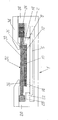
図1、図2において、符号1は撮像素子ユニットを示している。撮像素子ユニット1は、基板2に以下の各部材が組み込まれることによって構成されている。基板2は平面形状が四角形の板状の部材からなり、上面側から周縁部を残して抉り取られた形をしていて、上下方向の中間部に内向きの突出部22が庇のように一体に形成されている。この突出部22は基板2の内面の四方に形成されていて、四方の突出部22で囲まれた四角形の空間には、この空間と同じ平面形状の光電変換素子支持部材8が嵌められ基板2に固定されている。光電変換素子支持部材8も上面側から抉られて四角形の凹陥部が形成され、この凹陥部には光電変換手段であるCCD10が落とし込まれ固定されている。CCD10は撮像素子(「画素」ともいう)が2次元的に配列され、一つ一つの撮像素子にはその前面に、赤:R、緑:Gまたは青:Bのカラーフィルタが規則的に配置され、CCD10の前面はカラーフィルタによるパターン面12となっている。
1 and 2,
上記光電変換素子支持部材8の下面と上記突出部22の下面とは同一面になっていて、これら光電変換素子支持部材8の下面と突出部22の下面にまたがって導電手段としてのフレキシブル回路基板6の端部が固定され、フレキシブル回路基板6は撮像素子ユニット1の外方に引き出されている。フレキシブル回路基板6はCCD10の出力信号を外部回路に入力する。CCD10の上面側周縁部には、撮像素子を遮らない範囲にスペーサ14が固着され、スペーサ14の上にフィルタ30が乗せられている。フィルタ30は光電変換素子支持部材8の上面を覆い尽くすのに十分な面積を有し、また、スペーサ14上を滑りながら移動可能となっている。
The lower surface of the photoelectric conversion element support member 8 and the lower surface of the
基板2は、上面側に外周壁24を有し、この外周壁24の上にフィルタ押さえ34が固定されている。フィルタ押さえ34は基板2の内方に向かってCCD10の撮像素子を遮らない位置まで延び出ていて、その先端部下面に設けられた突起36がフィルタ30の上面に点接触または線接触してフィルタ30をCCD10に向かって適度の力で押し付けている。フィルタ30の上面は、後で詳細に説明する分光フィルタ面32となっている。フィルタ30は上面から見て四角形になっていて、相対向する一対の辺の一方と基板2の外周壁24の間には電移変換手段(アクチュエータ)としての圧電素子26が、他方の辺と基板2の外周壁24の間には弾性部材28が介在している。圧電素子26は、1層または適宜の複数層をなしていて、印加される電圧に応じて伸縮する。弾性部材28は、圧電素子26が伸びることによってフィルタ30が移動するのに伴い圧縮されて付勢され、圧電素子26が縮小するときは付勢力によりフィルタ30を逆向きに移動させる働きをする。弾性部材28は、コイルばね、板ばね、ゴムなど適宜のものを選択して採用して差し支えない。
The
上記フィルタ30は減光フィルタ部と無色フィルタ部を有し、これら減光フィルタ部と無色フィルタ部の形成パターンによって、以下に述べるような各種の実施例がある。
The
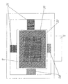
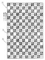
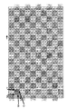
図3ないし図7は、実施例1におけるフィルタ30の構成を示す。図4はCCD10の各画素に配置されたカラーフィルタとフィルタ30の重なり合いの一態様を、図5はフィルタ30が1画素分移動したときの上記各画素に配置されたカラーフィルタとフィルタ30の重なり合いの態様を、図6、図7はフィルタ30の作用を示している。図3ないし図5において、フィルタ30は減光手段として機能するもので、光電変換手段であるCCD10の前面に配置され、CCD10の撮像素子配列方向にこの撮像素子配列と同じピッチで減光フィルタが配列されることによって構成されている。フィルタ30は、CCD10の各撮像素子の前面に配置されているカラーフィルタと分光的に補色光を透過するフィルタを有する減光フィルタ部38と、透過光をほとんど減光することなく透過させる無色フィルタ部39が、縦方向と横方向においてそれぞれ交互に市松模様状に配列されることによって構成されている。一つ一つの減光フィルタ部38は縦横に4分割され、各分割部分にY:イエロー、M:マゼンタ、C:シアンのフィルタ部が割り当てられている。ただし、一組の対角位置にある分割部分にMフィルタが割り当てられ、他の対角位置にある分割部分にはYとMが割り当てられている。減光フィルタ部38の4分割された各フィルタ部はCCD10の各撮像素子のカラーフィルタに対応して各撮像素子の前面に位置している。
3 to 7 show the configuration of the
図3に示す状態では、減光フィルタ部38のY、M、Cフィルタ部とY、M、Cフィルタ部が存在しない無色フィルタ部39が、CCD10の各撮像素子のB、G、Cフィルタの前面に縦横方向に交互に位置している。上記Y、M、Cフィルタ部はCCD10の分光感度の高い波長の光成分を減衰するもので、Y、M、Cフィルタ部に対応するCCD10の撮像素子は上記フィルタ部で減光された画像情報を取得することができる。この画像情報と、Y、M、Cフィルタ部の無い無色フィルタ部39に対応する撮像素子の画像情報とを合成することにより、ダイナミックレンジの広い画像情報を取得することが可能である。
In the state shown in FIG. 3, the Y, M, and C filter portions of the neutral
図4は、CCD10の各画素に対する図3に示すフィルタ30の重なり合いの関係を示す。CCD10の各画素は、縦横2個、合計4個の画素を一つの単位としていて、各画素の前面にはカラーフィルタが配置されている。上記1単位の画素には、R:赤、G:緑、B:青、の3色のカラーフィルタが配置されていて、一つの対角位置にある二つの画素はG、他の対角位置にある画素はB、Rの画素として割り当てられている。そして、Gの画素は上記Mのカラーフィルタと対向し、Bの画素はYのカラーフィルタと対向し、Rの画素はCのカラーフィルタと対向している。
FIG. 4 shows the relationship of the overlap of the
図4に示すフィルタとCCD10の画素との位置関係では、Y、M、Cのフィルタは画素の分光感度の高い光成分を減衰しない組み合わせになっており、フィルタによる入射像の光量を減らすことなく精細度の高い画像情報を取得することができる。その理由を、図6を参照しながら説明する。図6は、図4に示す状態の光波長成分の分割透過の状態を説明するものである。図9の上段に示す矢印は白色光が入射した場合の分光成分であり、左からB:ブルー、G:グリーン、R:レッドを示している。これらの矢印の下に減光手段すなわちフィルタ30の減光フィルタ部38がある。減光フィルタ部38は、分光透過特性の多い分光成分により、Y:イエロー、M:マゼンタ、C:シアンのフィルタ部に区分されている。
In the positional relationship between the filter shown in FIG. 4 and the pixel of the
フィルタ30の下にこのフィルタ30を透過した光の分光成分を矢印で示している。分光成分を示す矢印のうち細い線(点線)で表す矢印が上記減光フィルタ部38で減光された光成分を示している。その下にCCD10の撮像素子ごとに配置されたカラーフィルタがある。カラーフィルタは分光透過特性の多い分光成分によって前述のようにB:ブルー、G:グリーン、R:レッドに区分されている。フィルタ30の減光フィルタ部38とCCD10のカラーフィルタは補色の関係になっている。図4、図6の状態では、減光フィルタ部38を透過する光については、図6に「受光」の文字で示すように、CCD10の撮像素子に到達する光は減光手段である減光フィルタ部38により減光される。一方、無色フィルタ部39を透過する光は減光されることなくCCD10の撮像素子に到達する。
A spectral component of light transmitted through the
このように、図3、図6に示す状態では、減光フィルタ部38からなる減光手段により減光された画像情報(高輝度側)と、無色フィルタ部39を透過して減光されない画像情報(低輝度側)を得ることができ、これら2種類の画像情報を、図示されない画像処理手段により合成することにより、ダイナミックレンジの広い画像を形成することが可能である。しかし、上記画像処理を行うことにより、画像のコントラスト情報は減少する。
As described above, in the state shown in FIGS. 3 and 6, the image information (high luminance side) dimmed by the dimming means including the
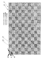
次に、図5、図7に示す減光手段としてのフィルタとCCD10の撮像素子との位置関係について説明する。図5、図7は、図4に示す状態からフィルタ30をCCD10の1画素分ずらした状態を示している。このようにフィルタ30をずらすためには、図1、図2について説明したアクチュエータとしての圧電素子26に電圧を印加し、あるいは印加していた電圧をオフにして圧電素子26を伸縮させることによって行うことができる。この動作態様では、フィルタ30の減光フィルタ部38を構成する4つのフィルタが、CCD10の撮像素子に配置されているカラーフィルタに対し、以下の対応関係をもって対抗している。CCD10の1単位の画素を構成する4個の画素のうち対角位置にあるGの画素の一つはYのフィルタと、もう一つのGの画素はMのフィルタと対向し、Bの画素はMのフィルタと対向し、Rの画素はCのフィルタと対向している。
Next, the positional relationship between the filter as the dimming means shown in FIGS. 5 and 7 and the image sensor of the
図5に示すフィルタ30の移動位置では、CCD10のカラーフィルタに対してフィルタ30の減光フィルタ部38が図7に示すような相対位置関係にあって、CCD10のカラーフィルタの分光特性と減光フィルタ部38の分光特性が互いに補色関係でない組み合わせになっている。したがって、図7に示すように、減光フィルタ部38を透過してCCD10の受光素子に向かう光は、分光的に減光フィルタ部38によって減光されることなく撮像素子に到達することができる。一方、無色フィルタ部39を透過する光は減光されることなくCCD10の撮像素子に到達する。
At the moving position of the
このように、図5に示す動作態様では、CCD10のダイナミックレンジは拡大できないが、コントラスト情報が減少することなく高画質の画像を得ることができる。
以上説明した実施例1によれば、ダイナミックレンジの広い画像を形成することができる動作態様と、高いコントラストで高い品質の画像を形成することができる動作態様とを切り換えることができる。この二つの動作態様相互の切り換えは、ユーザが手動で行うようにしてもよいが、例えば、測光装置の測光結果によって自動的に切り換えるように構成してもよい。
As described above, in the operation mode shown in FIG. 5, the dynamic range of the
According to the first embodiment described above, it is possible to switch between an operation mode capable of forming an image with a wide dynamic range and an operation mode capable of forming a high-quality image with high contrast. Switching between the two operation modes may be performed manually by the user, but for example, it may be configured to automatically switch according to the photometric result of the photometric device.
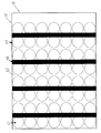
図8ないし図11は実施例2を示す。図8において、CCD10を構成する各撮像素子の前面には、各撮像素子の配列ピッチに合わせてマイクロレンズ62が配列されてなるマイクロレンズアレイ60が配置されている。このマイクロレンズアレイ60の前面には減光フィルタ部64が帯状に形成されたフィルタ30が、図1、図2に示すような構成によってその平面方向、より正確には帯状の減光フィルタ部64の長さ方向に対し直交する方向に移動可能に配置されている。減光フィルタ部64の形成ピッチはマイクロレンズアレイ60の2列分のピッチと等しくなっている。減光フィルタ部64以外のフィルタ30の面は、透過光をほとんど減光することなく透過させる無色フィルタ部65となっている。帯状の減光フィルタ部64の幅は、CCD10の列を成す画素相互の間隔よりも広くなっている。図8に示すフィルタ30の位置では、減光フィルタ部64が撮像素子列相互間にある。このとき、マイクロレンズ62を通してCCD10の画素11に入射する光束66の様子を図10に示す。図8、図10からもわかるとおり、入射光束66は減光フィルタ部64でほとんど遮られることなく、無色フィルタ部65を通って撮像素子11に到達する。
8 to 11 show the second embodiment. In FIG. 8, a
図9は、フィルタ30が画素11の1/2ピッチ分ずれた状態を示す。このとき、マイクロレンズ62を通してCCD10の撮像素子11に入射する光束66の様子を図11に示す。図9、図11からわかるとおり、入射光束66の一部がフィルタ30の減光フィルタ部64で遮られ、CCD10への入射光量が減衰しており、CCD10の各撮像素子からは減光された画像情報が出力されるようになっている。前面に減光フィルタ部64が存在しない撮像素子11には無色フィルタ部65を通ってほとんど減光されることなく入射する。そこで、減光フィルタ部64の無い無色フィルタ部65に対応する画素(撮像素子)の画像情報と、減光フィルタ部64で入射光量が減衰された画素の画像情報を合成することにより、ダイナミックレンジの広い画像情報を取得することができる。
FIG. 9 shows a state where the
図9、図11に示す動作態様は、入射光量が最も減衰する態様であるのに対し、図8、図10に示す動作態様は、減光フィルタ部64が撮像素子11のマイクロレンズ62の光路外に位置して光量を減衰しない態様であり、これらの態様において得られる画像情報を合成することにより、精細度の高い画像情報を取得することができる。
The operation modes shown in FIGS. 9 and 11 are the modes in which the amount of incident light is most attenuated, whereas the operation modes shown in FIGS. 8 and 10 are the optical paths of the
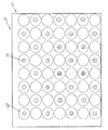
図12ないし図14は実施例3を示す。実施例3も実施例2に似た着想に基づくもので、実施例2におけるフィルタ30の帯状の減光フィルタ部64に代えて、図14に示すように、円形状の減光フィルタ部66を形成し、その他を無色フィルタ部としたものである。CCD10は実施例2におけるCCD10と同様に、撮像素子ごとにマイクロレンズ62を有している。減光フィルタ部66の外径は、マイクロレンズ62の外径よりもかなり大きく(例えば、3〜4倍)なっている。減光フィルタ部66は、上記画素のピッチに対し、縦横方向ともに2ピッチ分に対応したピッチで配置されている。また、図2に示すように、フィルタ30を互いに直交する方向に移動させることができるように配置された一対の圧電素子26によって、互いに直交する方向に最大で上記画素ピッチの1/2ピッチ分移動させることができるように構成されている。
12 to 14 show a third embodiment. The third embodiment is also based on an idea similar to that of the second embodiment. Instead of the band-shaped neutral
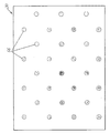
図12に示す動作態様では、フィルタ30の各減光フィルタ部66がCCD10の各画素間、したがって各マイクロレンズ62間にあって、CCD10の各撮像素子の入射光路上に無色フィルタ部のみが位置する。図13に示す動作態様は、フィルタ30が互いに直交する方向に上記画素ピッチの1/2ピッチ分移動した状態を示している。この動作態様では、減光フィルタ部66が入射光量を最も多く遮り、減光フィルタ部66が存在する位置の画素への入射光量は減衰する。一方、減光フィルタ部66が存在せず、無色フィルタ部が存在する位置の画素への入射光量はほとんど減衰しない。よって、これらの態様において得られる画像情報を合成することにより、精細度の高い画像情報を取得することができる。
In the operation mode shown in FIG. 12, the neutral
以上説明した各実施例において、減光手段としてのフィルタ30の全体に、赤外線カット特性などの分光特性を備えてもよい。
In each of the embodiments described above, the
以上説明した各実施例にかかる撮像装置は、以下に述べるような各種装置に適用することができる。
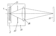
例えば、各種カメラの撮影レンズ鏡胴に組み込むことができる。図15はその例を示している。図15において、撮像素子ユニット1、絞り42、撮影光学系44を基体に組み込むことによって撮影光学ユニット40が構成されている。この撮影光学ユニット40を適宜の鏡胴に組み込むことにより撮影レンズ鏡胴が構成される。撮影レンズ鏡胴を各種カメラなどに組み込めば、被写体50の像を撮像素子ユニット1のCCDに結像させ、画像信号を出力させることができる。
The imaging apparatus according to each embodiment described above can be applied to various apparatuses as described below.
For example, it can be incorporated in the taking lens barrel of various cameras. FIG. 15 shows an example. In FIG. 15, the imaging
図16は、前記各実施例にかかる撮像装置をデジタルカメラに組み込んだ例を示す。図16において、カメラ本体に撮影光学ユニット40が組み込まれ、この撮影光学ユニット40の後部でありカメラ本体の内部に前記撮像素子ユニットが組み込まれている。
図17は、前記各実施例にかかる撮像装置を携帯情報端末、例えばノート型パソコンに組み込んだ例を示す。図17において、ノート型パソコンの蓋に撮影光学ユニット40が組み込まれ、この撮影光学ユニット40の後部であり上記蓋の内部に前記撮像素子ユニットが組み込まれている。
FIG. 16 shows an example in which the image pickup apparatus according to each of the embodiments is incorporated in a digital camera. In FIG. 16, a photographic
FIG. 17 shows an example in which the image pickup apparatus according to each of the embodiments is incorporated in a portable information terminal, for example, a notebook personal computer. In FIG. 17, the photographing
撮影レンズ鏡胴、デジタルカメラ、携帯情報端末に前記各実施例にかかる撮像装置を組み込むことにより、前記各実施例について説明したとおり、ダイナミックレンジを拡大することができるとともに、精細度の高い画像を得ることができる。 By incorporating the imaging device according to each of the above examples into a photographing lens barrel, a digital camera, and a portable information terminal, the dynamic range can be expanded as described in each of the above examples, and an image with high definition can be obtained. Obtainable.
1 撮像素子ユニット
2 基板
10 光電変換手段(CCD)
11 画素
12 パターン面
26 圧電素子(アクチュエータ)
28 弾性部材
30 フィルタ
32 分光フィルタ面
38 減光フィルタ部
39 無色フィルタ部
40 撮影光学ユニット
60 マイクロレンズアレイ
62 マイクロレンズ
64 減光フィルタ部
65 無色フィルタ部
66 減光フィルタ部
1
11
28
Claims (12)
前記光電変換手段の各撮像素子の前面で撮像素子に入射する光路上に配置され前記カラーフィルタの分光的に補色光を透過するフィルタを有する減光フィルタ部と透過光をほとんど減光することなく透過させる無色フィルタ部を有する減光手段と、
前記減光手段を前記光電変換手段に対し移動させ、前記カラーフィルタの分光特性と前記減光手段の分光特性が互いに補色関係である第1の状態または前記撮像素子のカラーフィルタの分光特性と前記減光手段の分光特性が互いに補色関係でない組み合わせになる第2の状態に切り換え可能な切り換え手段と、を備えている撮像装置。 Photoelectric conversion means comprising a plurality of image sensors with different color filters arranged on the front surface;
A neutral density filter portion having a filter that is arranged on the optical path incident on the image sensor on the front surface of each image sensor of the photoelectric conversion means and transmits the complementary color light spectrally of the color filter, and hardly attenuates transmitted light. A dimming means having a colorless filter portion to transmit;
The dimming means is moved relative to the photoelectric conversion means, the first state where the spectral characteristics of the color filter and the spectral characteristics of the dimming means are complementary to each other, or the spectral characteristics of the color filter of the image sensor and the An image pickup apparatus comprising: a switching unit capable of switching to a second state in which the spectral characteristics of the light reducing unit are in a combination that is not complementary to each other.
前記光電変換手段の撮像素子各々の前面で前記撮像素子に入射する光路上に配置され減光フィルタ部と透過光をほとんど減光することなく透過させる無色フィルタ部を有する減光手段と、
前記撮像素子の入射光路上に前記減光フィルタ部が位置する第1の状態と、前記減光手段を前記光電変換手段に対し移動して前記撮像素子の入射光路上の前記減光フィルタ部の前記光路の光軸垂直断面で前記減光フィルタ部の占める割合が変化する第2の状態に切り換え可能な切り換え手段と、を備えている撮像装置。 Photoelectric conversion means having a plurality of imaging elements;
A dimming unit having a neutral density filter unit disposed on an optical path incident on the image sensor on the front surface of each image sensor of the photoelectric conversion unit and a colorless filter unit that transmits the transmitted light with almost no attenuation;
A first state in which the neutral density filter unit is positioned on an incident optical path of the image sensor; and the neutral density filter unit on the incident optical path of the image sensor by moving the neutral density unit relative to the photoelectric conversion unit. An imaging apparatus comprising: switching means capable of switching to a second state in which a ratio occupied by the neutral density filter section changes in a cross section perpendicular to the optical axis of the optical path.
前記光電変換手段の撮像素子各々の前面で前記撮像素子に入射する光路上に配置され減光フィルタ部と透過光をほとんど減光することなく透過させる無色フィルタ部を有する減光手段と、
前記撮像素の入射光路上に前記減光フィルタ部が位置する第1の状態と、前記減光手段を前記光電変換手段に対し移動して前記撮像素子の入射光路上に前記無色フィルタ部のみが位置する第2の状態に切り換え可能な切り換え手段と、を備えている撮像装置。 Photoelectric conversion means having a plurality of imaging elements;
A dimming unit having a neutral density filter unit disposed on an optical path incident on the image sensor on the front surface of each image sensor of the photoelectric conversion unit and a colorless filter unit that transmits the transmitted light with almost no attenuation;
A first state in which the neutral density filter unit is positioned on the incident optical path of the imaging element, and the neutral density filter unit is only on the incident optical path of the imaging element by moving the neutral density unit relative to the photoelectric conversion unit. Switching means switchable to a second state that is positioned.
Priority Applications (1)
| Application Number | Priority Date | Filing Date | Title |
|---|---|---|---|
| JP2008190499A JP5047895B2 (en) | 2008-07-24 | 2008-07-24 | Imaging device, photographing lens barrel, digital camera, and portable information terminal |
Applications Claiming Priority (1)
| Application Number | Priority Date | Filing Date | Title |
|---|---|---|---|
| JP2008190499A JP5047895B2 (en) | 2008-07-24 | 2008-07-24 | Imaging device, photographing lens barrel, digital camera, and portable information terminal |
Publications (2)
| Publication Number | Publication Date |
|---|---|
| JP2010028697A true JP2010028697A (en) | 2010-02-04 |
| JP5047895B2 JP5047895B2 (en) | 2012-10-10 |
Family
ID=41734057
Family Applications (1)
| Application Number | Title | Priority Date | Filing Date |
|---|---|---|---|
| JP2008190499A Expired - Fee Related JP5047895B2 (en) | 2008-07-24 | 2008-07-24 | Imaging device, photographing lens barrel, digital camera, and portable information terminal |
Country Status (1)
| Country | Link |
|---|---|
| JP (1) | JP5047895B2 (en) |
Cited By (1)
| Publication number | Priority date | Publication date | Assignee | Title |
|---|---|---|---|---|
| CN109768060A (en) * | 2017-11-09 | 2019-05-17 | 松下知识产权经营株式会社 | Photographic device and camera arrangement |
Citations (5)
| Publication number | Priority date | Publication date | Assignee | Title |
|---|---|---|---|---|
| JPH05111037A (en) * | 1991-10-15 | 1993-04-30 | Konica Corp | Solid-state image pickup element |
| JP2001267543A (en) * | 2000-03-21 | 2001-09-28 | Sony Corp | Solid-state image pickup device and camera system using the same |
| JP2002112110A (en) * | 2000-09-28 | 2002-04-12 | Matsushita Electric Ind Co Ltd | Solid-state image pickup device and recording medium |
| JP2003179819A (en) * | 2001-12-12 | 2003-06-27 | Matsushita Electric Ind Co Ltd | Image pickup device |
| JP2004096358A (en) * | 2002-08-30 | 2004-03-25 | Olympus Corp | Imaging device |
-
2008
- 2008-07-24 JP JP2008190499A patent/JP5047895B2/en not_active Expired - Fee Related
Patent Citations (5)
| Publication number | Priority date | Publication date | Assignee | Title |
|---|---|---|---|---|
| JPH05111037A (en) * | 1991-10-15 | 1993-04-30 | Konica Corp | Solid-state image pickup element |
| JP2001267543A (en) * | 2000-03-21 | 2001-09-28 | Sony Corp | Solid-state image pickup device and camera system using the same |
| JP2002112110A (en) * | 2000-09-28 | 2002-04-12 | Matsushita Electric Ind Co Ltd | Solid-state image pickup device and recording medium |
| JP2003179819A (en) * | 2001-12-12 | 2003-06-27 | Matsushita Electric Ind Co Ltd | Image pickup device |
| JP2004096358A (en) * | 2002-08-30 | 2004-03-25 | Olympus Corp | Imaging device |
Cited By (1)
| Publication number | Priority date | Publication date | Assignee | Title |
|---|---|---|---|---|
| CN109768060A (en) * | 2017-11-09 | 2019-05-17 | 松下知识产权经营株式会社 | Photographic device and camera arrangement |
Also Published As
| Publication number | Publication date |
|---|---|
| JP5047895B2 (en) | 2012-10-10 |
Similar Documents
| Publication | Publication Date | Title |
|---|---|---|
| US7233359B2 (en) | Image sensing apparatus having image signals generated from light between optical elements of an optical element array | |
| CN101821657B (en) | Image sensing apparatus | |
| US8611738B2 (en) | Image capturing apparatus | |
| JP5092685B2 (en) | Imaging device and imaging apparatus | |
| JP5045350B2 (en) | Imaging device and imaging apparatus | |
| US20080291311A1 (en) | Image pickup device, focus detection device, image pickup apparatus, method for manufacturing image pickup device, method for manufacturing focus detection device, and method for manufacturing image pickup apparatus | |
| US9197827B2 (en) | Imaging device and imaging method | |
| JP4826507B2 (en) | Focus detection apparatus and imaging apparatus | |
| US8928774B2 (en) | Image capture apparatus | |
| JP2009159226A (en) | Imaging element, focus detection device, focus adjustment device and imaging apparatus | |
| JPWO2005081020A1 (en) | Optics and beam splitters | |
| EP2318873A1 (en) | Image-capturing apparatus | |
| JP6019556B2 (en) | Focus detection device, imaging device, and camera. | |
| JP5501448B2 (en) | Imaging apparatus and solid-state imaging device driving method | |
| JP2013057761A (en) | Distance measuring device, imaging device, and distance measuring method | |
| WO2018181358A1 (en) | Imaging device, and imaging element | |
| JP5278123B2 (en) | Imaging device | |
| JP2010212649A (en) | Image sensor | |
| JP5047895B2 (en) | Imaging device, photographing lens barrel, digital camera, and portable information terminal | |
| JP5329348B2 (en) | Solid-state imaging device and imaging apparatus using the same | |
| JP5228777B2 (en) | Focus detection apparatus and imaging apparatus | |
| JP2013003486A (en) | Focus detector and imaging apparatus | |
| JP2013011783A (en) | Focus detection device and imaging apparatus | |
| JP2016018033A (en) | Imaging device, control method of the same, program and recording medium | |
| JP6098097B2 (en) | Focus adjustment device, focus detection device, and imaging device |
Legal Events
| Date | Code | Title | Description |
|---|---|---|---|
| A621 | Written request for application examination |
Free format text: JAPANESE INTERMEDIATE CODE: A621 Effective date: 20110408 |
|
| A977 | Report on retrieval |
Free format text: JAPANESE INTERMEDIATE CODE: A971007 Effective date: 20120622 |
|
| TRDD | Decision of grant or rejection written | ||
| A01 | Written decision to grant a patent or to grant a registration (utility model) |
Free format text: JAPANESE INTERMEDIATE CODE: A01 Effective date: 20120703 |
|
| A01 | Written decision to grant a patent or to grant a registration (utility model) |
Free format text: JAPANESE INTERMEDIATE CODE: A01 |
|
| A61 | First payment of annual fees (during grant procedure) |
Free format text: JAPANESE INTERMEDIATE CODE: A61 Effective date: 20120718 |
|
| FPAY | Renewal fee payment (event date is renewal date of database) |
Free format text: PAYMENT UNTIL: 20150727 Year of fee payment: 3 |
|
| R150 | Certificate of patent or registration of utility model |
Ref document number: 5047895 Country of ref document: JP Free format text: JAPANESE INTERMEDIATE CODE: R150 Free format text: JAPANESE INTERMEDIATE CODE: R150 |
|
| LAPS | Cancellation because of no payment of annual fees |