JP2010027443A - Fuel cell system - Google Patents
Fuel cell system Download PDFInfo
- Publication number
- JP2010027443A JP2010027443A JP2008188512A JP2008188512A JP2010027443A JP 2010027443 A JP2010027443 A JP 2010027443A JP 2008188512 A JP2008188512 A JP 2008188512A JP 2008188512 A JP2008188512 A JP 2008188512A JP 2010027443 A JP2010027443 A JP 2010027443A
- Authority
- JP
- Japan
- Prior art keywords
- cathode
- fuel cell
- anode
- gas
- closing
- Prior art date
- Legal status (The legal status is an assumption and is not a legal conclusion. Google has not performed a legal analysis and makes no representation as to the accuracy of the status listed.)
- Granted
Links
Images


Classifications
-
- Y—GENERAL TAGGING OF NEW TECHNOLOGICAL DEVELOPMENTS; GENERAL TAGGING OF CROSS-SECTIONAL TECHNOLOGIES SPANNING OVER SEVERAL SECTIONS OF THE IPC; TECHNICAL SUBJECTS COVERED BY FORMER USPC CROSS-REFERENCE ART COLLECTIONS [XRACs] AND DIGESTS
- Y02—TECHNOLOGIES OR APPLICATIONS FOR MITIGATION OR ADAPTATION AGAINST CLIMATE CHANGE
- Y02E—REDUCTION OF GREENHOUSE GAS [GHG] EMISSIONS, RELATED TO ENERGY GENERATION, TRANSMISSION OR DISTRIBUTION
- Y02E60/00—Enabling technologies; Technologies with a potential or indirect contribution to GHG emissions mitigation
- Y02E60/30—Hydrogen technology
- Y02E60/50—Fuel cells
Abstract
Description
本発明は燃料電池システムに関する。 The present invention relates to a fuel cell system.
燃料電池システムは、アノードおよびカソードをもつ燃料電池と、改質装置から燃料電池のアノードにアノードガスを供給するためのアノードガス通路と、燃料電池のアノードの上流に設けられ改質装置で生成されたアノードガスに含まれるCO(一酸化炭素)濃度を低減させるCO低減部と、酸素を含むカソードガスを燃料電池のカソードに供給するためのカソードガス通路と、燃料電池のカソードの入口側を開閉するための入口開閉部と、燃料電池のカソードの出口側を開閉するための出口開閉部と、入口開閉部および出口開閉部を制御するための制御部とを有する。 The fuel cell system is a fuel cell having an anode and a cathode, an anode gas passage for supplying anode gas from the reformer to the anode of the fuel cell, and a reformer provided upstream of the anode of the fuel cell. A CO reduction section for reducing the CO (carbon monoxide) concentration contained in the anode gas, a cathode gas passage for supplying a cathode gas containing oxygen to the cathode of the fuel cell, and an inlet side of the fuel cell cathode being opened and closed An opening / closing portion for opening / closing, an outlet opening / closing portion for opening / closing the outlet side of the cathode of the fuel cell, and a control portion for controlling the inlet opening / closing portion and the outlet opening / closing portion.
燃料電池システムの運転の起動時において、改質装置で生成されるアノードガスの組成の安定性は必ずしも充分ではなく、アノードガスは、所定濃度を超えるCOを含むおそれがある。COを含むアノードガスを、発電運転している燃料電池のアノードに供給することは、好ましくない。燃料電池が発電運転中であると、アノードに保持されている触媒がCO被毒により劣化するためである。そこで、従来のシステムでは迂回通路が設けてられている(特許文献1)。そして、システムの運転の起動時において、改質装置で生成されるアノードガスの組成の安定性が必ずしも充分ではないときには、アノードガスを迂回通路に流すことにより燃料電池のアノードを迂回させ、アノードに供給させないようにしている。これにより燃料電池のアノードの触媒がCO被毒により劣化することを抑えている。上記した迂回通路では、システムの定常運転時にアノードガスが迂回通路を流れないように迂回通路を閉鎖する迂回バルブが必要とされている。
上記した特許文献1に係る技術は、発電中の燃料電池のアノードの触媒がCO被毒により劣化することを抑えているが、システムの起動時においてアノードガスが燃料電池のアノードを迂回するように流れる迂回通路、さらには、迂回通路を開閉させる迂回バルブが必要とされる。 The technique according to Patent Document 1 described above suppresses deterioration of the anode catalyst of the fuel cell during power generation due to CO poisoning, but the anode gas bypasses the anode of the fuel cell when the system is started. A bypass path that flows and a bypass valve that opens and closes the bypass path are required.
本発明は上記した実情に鑑みてなされたものであり、アノードガスが燃料電池のアノードを迂回するための迂回通路と、迂回通路を開閉させる迂回バルブとを廃止させることができる燃料電池システムを提供することを課題とする。 The present invention has been made in view of the above circumstances, and provides a fuel cell system capable of eliminating a bypass passage for the anode gas to bypass the anode of the fuel cell and a bypass valve for opening and closing the bypass passage. The task is to do.
(1)様相1に係る燃料電池システムは、アノードおよびカソードをもつ燃料電池と、COを含む可能性があるアノードガスを燃料電池のアノードに供給するためのアノードガス通路と、燃料電池のアノードの上流に設けられアノードガスに含まれるCO濃度を低減させるCO低減部と、酸素を含むカソードガスを燃料電池のカソードに供給するためのカソードガス通路と、燃料電池のカソードの入口側を開閉するための入口開閉部と、燃料電池のカソードの出口側を開閉するための出口開閉部と、少なくとも入口開閉部および出口開閉部を制御するための制御部とを具備する燃料電池システムにおいて、
燃料電池システムの運転の起動時において、制御部は、(i)入口開閉部および出口開閉部を閉鎖して燃料電池のカソードを封止した状態で、燃料電池のアノードに前記アノードガスを供給させる第1制御を実施し、(ii)その後、入口開閉部および出口開閉部を開放させた状態で、燃料電池のアノードにアノードガスを供給しつつ、燃料電池の発電量に応じてカソードガスを燃料電池の前記カソードに供給する第2制御を実施する。
(1) A fuel cell system according to aspect 1 includes a fuel cell having an anode and a cathode, an anode gas passage for supplying an anode gas that may contain CO to the anode of the fuel cell, and an anode of the fuel cell. A CO reduction unit that is provided upstream to reduce the concentration of CO contained in the anode gas, a cathode gas passage for supplying a cathode gas containing oxygen to the cathode of the fuel cell, and an inlet side of the cathode of the fuel cell A fuel cell system comprising: an inlet opening and closing part; an outlet opening and closing part for opening and closing an outlet side of the cathode of the fuel cell; and a control part for controlling at least the inlet opening and closing part and the outlet opening and closing part.
At the start of operation of the fuel cell system, the control unit (i) supplies the anode gas to the anode of the fuel cell with the inlet opening / closing unit and the outlet opening / closing unit closed and the fuel cell cathode sealed. (Ii) After that, with the inlet opening / closing part and the outlet opening / closing part being opened, the anode gas is supplied to the anode of the fuel cell, and the cathode gas is fueled according to the power generation amount of the fuel cell. A second control for supplying the cathode of the battery is performed.
上記したように燃料電池システム(以下、システムともいう)の運転の起動時において、制御部は、燃料電池のアノードにアノードガスを供給させる。しかしながら、カソードの入口開閉部および出口開閉部が閉鎖されており、カソードは封止された状態とされている。従って、システムの起動時において、アノードガスは、燃料電池のアノードを迂回することなく、燃料電池のアノードに供給される。従って、燃料電池のアノードを迂回させるために従来必要とされていた迂回通路および迂回バルブを廃止することができる利点が得られ、配管の複雑化が抑制される。 As described above, at the start of operation of a fuel cell system (hereinafter also referred to as a system), the control unit supplies anode gas to the anode of the fuel cell. However, the inlet opening / closing part and the outlet opening / closing part of the cathode are closed, and the cathode is sealed. Therefore, at the time of starting the system, the anode gas is supplied to the anode of the fuel cell without bypassing the anode of the fuel cell. Therefore, there is an advantage that the bypass passage and the bypass valve that are conventionally required for bypassing the anode of the fuel cell can be eliminated, and the complication of the piping is suppressed.
ここで、燃料電池において発電反応により水(2H2+O2→2H2O)が発生することを考慮すると、2モルのH2と1モルのO2とが化学量論的に当量であるといえる。上記したようにシステムの起動時には、カソードが封止され、カソードガスがカソードに供給されることが制限された状態で、アノードガスがアノードに積極的に供給される。このためアノードに供給されるアノード活物質(水素)のモル数に比較して、カソードにおけるカソード活物質(酸素)のモル数は、化学量論的に低減または欠乏された状態とされる。よって、第1制御においては、モル比によれば、H2のモル比2に対して、O2のモル比は1未満とされる。すなわち、システムの起動時において、カソードは酸素欠乏状態等の酸素低減状態に維持される。ここで、酸素低減状態とは、アノードに供給されるアノード活物質(水素)のモル数に比較して、カソードにおけるカソード活物質である酸素のモル数が化学量論的に低減また欠乏された状態を意味する。
Here, considering that water (2H 2 + O 2 → 2H 2 O) is generated by a power generation reaction in the fuel cell, 2 moles of H 2 and 1 mole of O 2 are stoichiometrically equivalent. I can say that. As described above, at the start-up of the system, the anode gas is positively supplied to the anode while the cathode is sealed and the supply of the cathode gas to the cathode is restricted. For this reason, compared with the number of moles of anode active material (hydrogen) supplied to the anode, the number of moles of cathode active material (oxygen) at the cathode is stoichiometrically reduced or depleted. Therefore, in the first control, according to the molar ratio, the molar ratio of O 2 is less than 1 with respect to the
上記したように本様相によれば、システムの起動時において、カソードにおける酸素が化学量論的に酸素欠乏状態等の酸素低減状態であるため、カソードの電位の上昇が制限され、OCVの過剰な上昇は抑制される。 As described above, according to this aspect, since the oxygen at the cathode is stoichiometrically in an oxygen-reduced state such as an oxygen-deficient state at the time of starting the system, the increase in the cathode potential is limited and the OCV is excessively excessive. The rise is suppressed.
開回路電圧(以下、OCVともいう)は、open circuit voltageであり、燃料電池のアノードとカソードとが電気的に接続されていない状態(燃料電池と電力負荷とが電気的に接続されていない状態)における燃料電池の両端子間の電圧差をいう。OCVは、燃料電池のアノードとカソードとが電力負荷を介して電気的に接続されている状態において燃料電池が発電する通常の発電電圧よりも、高い電圧となる。燃料電池の電位が触媒の平衡電極電位よりも過剰に上昇すると、燃料電池の触媒(特にカソードの触媒)において、酸素と、アノードから電解質を透過してカソードにいたる水素との酸化反応に進み、燃料電池の触媒(特にカソードの触媒)が電気化学的に劣化するおそれがある。このためOCVが過剰に上昇することは、できるだけ避けることが好ましい。 The open circuit voltage (hereinafter also referred to as OCV) is an open circuit voltage in which the anode and cathode of the fuel cell are not electrically connected (the fuel cell and the power load are not electrically connected). ) Is the voltage difference between both terminals of the fuel cell. The OCV has a higher voltage than a normal power generation voltage generated by the fuel cell in a state where the anode and the cathode of the fuel cell are electrically connected via a power load. When the fuel cell potential rises excessively above the equilibrium electrode potential of the catalyst, the fuel cell catalyst (especially the cathode catalyst) proceeds with an oxidation reaction between oxygen and hydrogen that permeates the electrolyte from the anode to the cathode, There is a possibility that the catalyst of the fuel cell (particularly the catalyst of the cathode) is electrochemically deteriorated. For this reason, it is preferable to avoid that OCV rises excessively as much as possible.
また、燃料電池が発電している場合には、COを含むアノードガスが燃料電池のアノードに供給されるとき、アノードの触媒のCO被毒は無視できない。但し、燃料電池の発電が制限されている限り、COを含むアノードガスが燃料電池のアノードに仮に供給されたとしても、燃料電池のアノードの触媒のCO被毒の可逆性が高くなり、アノードの触媒のCO被毒は抑制される。 Further, when the fuel cell is generating electric power, when the anode gas containing CO is supplied to the anode of the fuel cell, the CO poisoning of the anode catalyst cannot be ignored. However, as long as the power generation of the fuel cell is restricted, even if an anode gas containing CO is supplied to the anode of the fuel cell, the reversibility of the CO poisoning of the catalyst of the anode of the fuel cell increases, The CO poisoning of the catalyst is suppressed.
更に、システムの起動時において、アノード活物質の他にCOを含むアノードガスを燃料電池のアノードに積極的に供給したとしても、カソードにおける酸素が化学量論的に酸素欠乏状態等の酸素低減状態であるため、燃料電池の発電反応は制限される。この結果、燃料電池のアノードにおける触媒のCO被毒が抑制される利点が得られる。 Furthermore, even when an anode gas containing CO in addition to the anode active material is positively supplied to the anode of the fuel cell at the time of starting the system, oxygen at the cathode is in an oxygen-reduced state such as an oxygen-deficient state. Therefore, the power generation reaction of the fuel cell is limited. As a result, there is an advantage that CO poisoning of the catalyst at the anode of the fuel cell is suppressed.
本明細書によれば、燃料電池のカソードは酸化剤極であり、アノードは燃料極である。アノードガスはアノードに供給されるガスである。カソードガスはカソードに供給されるガスである。入口開閉部は、燃料電池のカソードの入口側を開閉するための要素であり、バルブなどが挙げられ、燃料電池自体に設けられていても良いし、燃料電池のカソードの入口に繋がる通路に設けられていても良い。出口開閉部は、燃料電池のカソードの出口側を開閉するため要素であり、バルブなどが挙げられ、燃料電池自体に設けられていても良いし、燃料電池のカソードの出口に繋がる通路に設けられていても良い。CO低減部は、燃料電池のアノードの上流に設けられており、改質装置で生成されたアノードガスに含まれるCO濃度を低減させる要素である。CO低減部は、COシフト部、CO酸化部、メタネーション反応部のうちの少なくとも一つで形成でき、要するにCO濃度を低減できる機能を有すれば良い。 According to the present specification, the cathode of the fuel cell is the oxidant electrode and the anode is the fuel electrode. The anode gas is a gas supplied to the anode. The cathode gas is a gas supplied to the cathode. The inlet opening / closing portion is an element for opening and closing the inlet side of the cathode of the fuel cell, and may be provided in the fuel cell itself, such as a valve, or provided in a passage leading to the cathode inlet of the fuel cell. It may be done. The outlet opening / closing unit is an element for opening and closing the outlet side of the cathode of the fuel cell, and includes a valve and the like, and may be provided in the fuel cell itself or provided in a passage connected to the outlet of the cathode of the fuel cell. May be. The CO reduction unit is an element that is provided upstream of the anode of the fuel cell and reduces the concentration of CO contained in the anode gas generated by the reformer. The CO reduction unit can be formed of at least one of a CO shift unit, a CO oxidation unit, and a methanation reaction unit, and in short, it only needs to have a function of reducing the CO concentration.
様相1は次の好適態様のうちの少なくとも一つを採用できる。 The aspect 1 can employ at least one of the following preferred embodiments.
・燃料電池のアノードに供給するためのアノードガスを改質用燃料から改質反応により生成させるための改質装置がアノードガス供給源としてCO低減部の上流に設けられていることが好ましい。多数の燃料電池システムが設けられているときには、改質装置が共用されていても良い。好ましくは、改質装置は、燃焼用燃料を燃焼用空気で燃焼させるためのバーナと、バーナにより改質反応に適するように加熱されてアノードガスを生成させるための改質部とを有する。また、燃料電池のアノードに供給するためのアノードガスを貯蔵するタンク等の貯蔵部がアノードガス供給源としてCO低減部の上流に設けられていても良い。
・システムの起動時において、CO低減部の暖機完了前では、CO低減部の温度が相対的に低いため、CO低減作用は充分ではない。この場合、燃料電池のアノードに供給されるアノードガスに含まれるCO濃度が高くなるおそれがあり、アノードにおける触媒のCO被毒のおそれが高くなる。これに対して、CO低減部の暖機完了後では、CO低減部の温度が相対的に高いため、CO低減作用が良好である。この場合、燃料電池のアノードに供給されるアノードガスに含まれるCO濃度が相対的に低くなり、アノードにおける触媒のCO被毒のおそれが低減される。そこで好ましくは、制御部は、CO低減部の暖機完了前において第1制御を実行し、燃料電池の発電反応を制限しつつ、且つ、CO低減部の暖機完了後において第2制御を実施し、スタックの発電反応を促進させる。この結果、第1制御において、アノードにおける触媒のCO被毒のおそれが低減される。
It is preferable that a reforming device for generating an anode gas to be supplied to the anode of the fuel cell from the reforming fuel by a reforming reaction is provided upstream of the CO reduction unit as an anode gas supply source. When a large number of fuel cell systems are provided, the reformer may be shared. Preferably, the reformer includes a burner for combusting combustion fuel with combustion air, and a reforming section that is heated by the burner so as to be suitable for a reforming reaction to generate anode gas. A storage unit such as a tank for storing anode gas to be supplied to the anode of the fuel cell may be provided upstream of the CO reduction unit as an anode gas supply source.
-At the time of starting the system, the CO reduction action is not sufficient because the temperature of the CO reduction part is relatively low before the completion of warming up of the CO reduction part. In this case, the concentration of CO contained in the anode gas supplied to the anode of the fuel cell may increase, and the risk of CO poisoning of the catalyst at the anode increases. On the other hand, after the warm-up of the CO reduction unit is completed, the CO reduction effect is good because the temperature of the CO reduction unit is relatively high. In this case, the CO concentration contained in the anode gas supplied to the anode of the fuel cell becomes relatively low, and the risk of CO poisoning of the catalyst at the anode is reduced. Therefore, preferably, the control unit executes the first control before the completion of warming-up of the CO reduction unit, and performs the second control after completion of warming-up of the CO reduction unit while limiting the power generation reaction of the fuel cell. And promote the power generation reaction of the stack. As a result, in the first control, the risk of CO poisoning of the catalyst at the anode is reduced.
・好ましくは、制御部は、第1制御において、燃料電池のアノードの入口に供給されたアノードガスを燃料電池のアノードの出口から排出させた後、アノードオフガス通路を介してバーナに供給してバーナで燃焼用空気により燃焼させることができる。システムの起動時には、改質装置で生成されるアノードガスの組成の安定性は必ずしも充分ではなく、アノードガスに含まれるCO濃度が高いことがある。そこで、制御部は、第1制御において、燃料電池(カソードでは酸素欠乏状態等の酸素低減状態)のアノードの入口にアノードガスを供給させるものの、燃料電池のアノードの出口から排出させた後、そのアノードガスをアノードオフガス通路を介してバーナに供給し、バーナで燃焼用空気により燃焼させることができる。第1制御においては、前述したように、燃料電池のカソードでは酸素欠乏状態等の酸素低減状態とされており、燃料電池の発電反応は制限されており、アノードの触媒のCO被毒が抑えられる。 Preferably, in the first control, the control unit discharges the anode gas supplied to the anode inlet of the fuel cell from the anode outlet of the fuel cell, and then supplies the anode gas to the burner via the anode off-gas passage. Can be burned with combustion air. When the system is started, the composition of the anode gas produced by the reformer is not necessarily stable, and the concentration of CO contained in the anode gas may be high. Therefore, in the first control, the control unit causes the anode gas to be supplied to the anode inlet of the fuel cell (oxygen-reduced state such as an oxygen-deficient state at the cathode), but after discharging it from the anode outlet of the fuel cell, Anode gas can be supplied to the burner via the anode off-gas passage and burned with combustion air in the burner. In the first control, as described above, the cathode of the fuel cell is in an oxygen-reduced state such as an oxygen-deficient state, the power generation reaction of the fuel cell is limited, and CO poisoning of the anode catalyst is suppressed. .
・好ましくは、出口開閉部は、燃料電池のカソードの出口側に設けられた逆止弁とすることができる。この場合、逆止弁は、燃料電池のカソードから排出されるカソードオフガスをカソードから排出される方向に流出させると共に、その逆の流れを阻止する。従って、酸素を含む外気が出口開閉部から燃料電池のカソードに進入することが抑えられる。この結果、システムの停止時から次の起動時までの間において、外気が燃料電池のカソードの内部に進入することが抑えられる。故に、カソードは、酸素が低減または欠乏された状態に維持され易い。従って次の起動時において、カソードは、酸素欠乏状態等の酸素低減状態に維持され易い。酸素低減状態は、カソードガスが本来有する酸素濃度よりも酸素濃度が少ない状態を意味する。 Preferably, the outlet opening / closing part can be a check valve provided on the outlet side of the cathode of the fuel cell. In this case, the check valve causes the cathode off-gas discharged from the cathode of the fuel cell to flow in the direction of being discharged from the cathode, and prevents the reverse flow. Therefore, the outside air containing oxygen can be prevented from entering the cathode of the fuel cell from the outlet opening / closing part. As a result, it is possible to prevent outside air from entering the cathode of the fuel cell between the time when the system is stopped and the time when the system is next started. Therefore, the cathode tends to be maintained in a state where oxygen is reduced or depleted. Therefore, at the next start-up, the cathode is easily maintained in an oxygen-reduced state such as an oxygen-deficient state. The oxygen reduced state means a state in which the oxygen concentration is lower than the oxygen concentration inherent in the cathode gas.
・好ましくは、カソードガスを燃料電池のカソードに供給するカソードガス搬送源が燃料電池のカソードの入口側に設けられており、入口開閉部はカソードガス搬送源に設けられていることができる。この結果、システムの停止時から次の起動時までも酸素を含む外気が入口開閉部から燃料電池のカソードに進入することが抑えられる。この結果、システムの起動時において、燃料電池のカソードの内部は、酸素を低減または消失された状態に維持され易い。ここで、カソードガス搬送源として、ポンプ、ファン、ブロア、コンプレッサなどが挙げられる。 -Preferably, the cathode gas conveyance source which supplies cathode gas to the cathode of a fuel cell is provided in the inlet side of the cathode of a fuel cell, and an inlet opening / closing part can be provided in the cathode gas conveyance source. As a result, it is possible to prevent the outside air containing oxygen from entering the cathode of the fuel cell from the inlet opening / closing section from the time when the system is stopped until the next startup. As a result, when the system is started, the inside of the cathode of the fuel cell is easily maintained in a state where oxygen is reduced or eliminated. Here, examples of the cathode gas transfer source include a pump, a fan, a blower, and a compressor.
・上記したシステム停止時において、燃料電池のアノードにアノードガスが存在し、カソードにカソードガスが存在するときには、燃料電池のアノードとカソードとが電気的に接続されていない場合には、燃料電池の開回路電圧(以下、OCVともいう)が所定値よりも過剰に上昇するおそれがある。そこで、第1制御において、燃料電池のOCVが所定値よりも上昇するとき、カソードにカソードガスが存在し、アノードにCO濃度が十分に低い(例えばPEFCでは10ppm以下)アノードガスが供給されており、且つ、燃料電池と電力消費部とが電気的に接続されている状態において、燃料電池に発生する電力は電力消費部で消費されることが好ましい。この場合、燃料電池のOCVの過剰な上昇が抑制される。更に、電力消費時において燃料電池の発電反応によりカソードの内部の酸素濃度は電力消費前よりも低減される。結果として、酸素低減状態がカソードに形成される。このように第1制御において、カソードにおける酸素欠乏状態等の酸素低減状態を形成することができる。上記した基準となる所定電圧値は、システム、燃料電池の触媒の材質等に応じて適宜設定できる。 -When the system is shut down, when anode gas is present at the anode of the fuel cell and cathode gas is present at the cathode, if the anode and cathode of the fuel cell are not electrically connected, There is a possibility that the open circuit voltage (hereinafter also referred to as OCV) rises excessively beyond a predetermined value. Therefore, in the first control, when the OCV of the fuel cell rises above a predetermined value, the cathode gas is present at the cathode, and the anode gas is supplied with a sufficiently low CO concentration (for example, 10 ppm or less in PEFC). In addition, in a state where the fuel cell and the power consumption unit are electrically connected, it is preferable that the power generated in the fuel cell is consumed by the power consumption unit. In this case, an excessive increase in the OCV of the fuel cell is suppressed. Furthermore, the oxygen concentration inside the cathode is reduced more than before power consumption due to the power generation reaction of the fuel cell during power consumption. As a result, an oxygen reduced state is formed at the cathode. Thus, in the first control, it is possible to form an oxygen reduced state such as an oxygen deficient state at the cathode. The predetermined voltage value serving as the reference can be appropriately set according to the system, the material of the fuel cell catalyst, and the like.
・好ましくは、燃料電池システムの運転の停止時において、制御部は、(i)燃料電池のカソードの出口開閉部を閉鎖し且つ入口開閉部を開放した状態で、燃料電池のカソードの内部が大気圧を超える高圧となるようにカソードに、酸素を含むカソードガスを供給する制御と、(ii)その後、出口開閉部を閉鎖した状態で入口開閉部を閉鎖させることにより、燃料電池のカソードの内部を大気圧よりも高圧とする制御と、(iii)その後、燃料電池のカソードにカソードガスが存在し、且つ、アノードにアノードガスが供給され、且つ、燃料電池と電力消費部とが電気的に接続された状態において、燃料電池に発生する電力を電力消費部で消費させる。これにより、制御部は、燃料電池のOCVの過剰な上昇を抑制しつつ、カソードの内部の酸素濃度を電力消費前よりも低減させる制御を実施する。この場合、カソードの内部に残留する酸素は、電力消費時における発電反応により消費されて低減される。このためカソードガスが空気であれば、不活性な窒素ガスの濃度がカソードにおいて高くなる。従って、燃料電池のカソードは、不活性な窒素ガスを封入した状態でシステムの次の起動時まで封止される。 Preferably, when the operation of the fuel cell system is stopped, the control unit (i) closes the outlet opening / closing unit of the fuel cell cathode and opens the inlet opening / closing unit, and the inside of the fuel cell cathode is large. Control of supplying a cathode gas containing oxygen to the cathode so as to have a high pressure exceeding atmospheric pressure, and (ii) after that, the inlet opening / closing part is closed while the outlet opening / closing part is closed. (Iii) After that, the cathode gas is present at the cathode of the fuel cell, the anode gas is supplied to the anode, and the fuel cell and the power consuming unit are electrically connected to each other. In the connected state, the power generated in the fuel cell is consumed by the power consuming unit. Thus, the control unit performs control to reduce the oxygen concentration inside the cathode more than before power consumption while suppressing an excessive increase in the OCV of the fuel cell. In this case, oxygen remaining inside the cathode is consumed and reduced by a power generation reaction during power consumption. For this reason, if the cathode gas is air, the concentration of the inert nitrogen gas increases at the cathode. Accordingly, the cathode of the fuel cell is sealed until the next start-up of the system with the inert nitrogen gas sealed.
ここで、大気圧を高圧側に超える圧力を有する不活性な窒素ガスが燃料電池のカソードの内部に封止されていることが好ましい。この場合、カソードの内部の圧力は大気圧よりも高いため、酸素を含む外気が燃料電池のカソードに進入することが効果的に抑制され、カソードの酸素低減状態が次の起動時まで良好に維持される。 Here, it is preferable that an inert nitrogen gas having a pressure exceeding the atmospheric pressure on the high pressure side is sealed inside the cathode of the fuel cell. In this case, since the internal pressure of the cathode is higher than the atmospheric pressure, the outside air containing oxygen is effectively suppressed from entering the cathode of the fuel cell, and the oxygen reduction state of the cathode is maintained well until the next start-up. Is done.
ここで、本明細書によれば、電力消費部とは、燃料電池で発生した電力を消費できる要素をいい、燃料電池の発電電力で駆動させる電力負荷に対して別に設けられた放電負荷、あるいは、ヒータ、あるいは、システムの補機類、あるいは、キャパシタ、蓄電池などの電力貯蔵部が挙げられる。補機類としては、バルブなどの通路開閉部、ファン、ポンプ、ブロア、コンプレッサ等の流体搬送源が挙げられる。 Here, according to the present specification, the power consuming unit refers to an element capable of consuming the power generated in the fuel cell, and a discharge load provided separately from the power load driven by the power generated by the fuel cell, or , Heaters, system accessories, or power storage units such as capacitors and storage batteries. Examples of the auxiliary machines include a passage opening / closing unit such as a valve, a fluid conveyance source such as a fan, a pump, a blower, and a compressor.
(2)様相2に係る燃料電池システムは、アノードおよびカソードをもつ燃料電池と、COを含む可能性があるアノードガスを燃料電池のアノードに供給するためのアノードガス通路と、燃料電池のアノードの上流に設けられアノードガスに含まれるCO濃度を低減させるCO低減部と、酸素を含むカソードガスを燃料電池のカソードに供給するためのカソードガス通路と、燃料電池のカソードの入口側を開閉するための入口開閉部と、燃料電池のカソードの出口側を開閉するための出口開閉部と、少なくとも入口開閉部および出口開閉部を制御するための制御部とを具備する燃料電池システムにおいて、
燃料電池システムの運転の停止時において、制御部は、燃料電池のカソードの入口開閉部と出口開閉部が閉鎖されてカソードが封止され、且つ、燃料電池のカソードにカソードガスが存在し、且つ、アノードにアノードガスが供給され、且つ、燃料電池と電力消費部とが電気的に接続された状態において、燃料電池の電力を電力消費部で消費させることにより、燃料電池の開回路電圧の過剰な上昇を抑制しつつ、カソードの内部の酸素濃度を電力消費前よりも低減させる制御を実施する。
(2) A fuel cell system according to
When the operation of the fuel cell system is stopped, the control unit closes the inlet opening / closing unit and the outlet opening / closing unit of the cathode of the fuel cell to seal the cathode, and the cathode gas exists in the cathode of the fuel cell, and When the anode gas is supplied to the anode and the fuel cell and the power consuming unit are electrically connected, the power consumption of the fuel cell is consumed by the power consuming unit. Control is performed to reduce the oxygen concentration inside the cathode more than before power consumption, while suppressing an excessive rise.
本様相によれば、システムの運転の停止時において、燃料電池のカソードの内部は、電力消費時における発電反応により、酸素を低減または欠乏させた状態とされる。そして、システムの次の発電運転まで、カソードの内部は、酸素を低減または消失された状態に維持される。この結果、システムを次に起動させるとき、アノードガスを燃料電池のアノードに積極的に供給したとしても、燃料電池の発電反応が抑制される。この結果、燃料電池のアノードとカソードとが電気的に接続されていないとき、OCVの過剰な上昇が低減される。且つ、燃料電池のアノードとカソードとが電気的に接続されているとき、燃料電池のアノードに保持されている触媒のCO被毒が抑制される。 According to this aspect, when the operation of the system is stopped, the inside of the cathode of the fuel cell is brought into a state in which oxygen is reduced or depleted by a power generation reaction during power consumption. Then, until the next power generation operation of the system, the inside of the cathode is maintained in a state where oxygen is reduced or eliminated. As a result, the power generation reaction of the fuel cell is suppressed even when the anode gas is positively supplied to the anode of the fuel cell when the system is next started. As a result, when the anode and cathode of the fuel cell are not electrically connected, an excessive increase in OCV is reduced. In addition, when the anode and cathode of the fuel cell are electrically connected, CO poisoning of the catalyst held on the anode of the fuel cell is suppressed.
(3)様相3に係る燃料電池システムは、アノードおよびカソードをもつ燃料電池と、COを含む可能性があるアノードガスを燃料電池のアノードに供給するためのアノードガス通路と、燃料電池のアノードの上流に設けられアノードガスに含まれるCO濃度を低減させるCO低減部と、酸素を含むカソードガスを燃料電池のカソードに供給するためのカソードガス通路と、燃料電池のカソードの入口側を開閉するための入口開閉部と、燃料電池のカソードの出口側を開閉するための出口開閉部と、少なくとも入口開閉部および出口開閉部を制御するための制御部とを具備する燃料電池システムにおいて、燃料電池システムの運転の停止時において、
制御部は、(i)燃料電池のカソードの出口開閉部が閉鎖され且つ入口開閉部が開放された状態において、燃料電池のカソードの内部が大気圧を高圧側に超える圧力となるようにカソードにカソードガスを供給する制御と、(ii)出口開閉部を閉鎖した状態で入口開閉部を閉鎖させることにより、カソードの内部を大気圧を超える高圧とさせる制御と、(iii)その後、燃料電池のカソードにカソードガスが存在し且つアノードにアノードガスが供給されている状態において、燃料電池と電力消費部とを電気的に接続させ、燃料電池に発生する電力を電力消費部で消費させることにより、燃料電池の開回路電圧(OCV)の過剰な上昇を抑制しつつ、カソードの内部の酸素濃度を電力消費前よりも低減させる制御を実施する。
(3) A fuel cell system according to aspect 3 includes a fuel cell having an anode and a cathode, an anode gas passage for supplying an anode gas that may contain CO to the anode of the fuel cell, and an anode of the fuel cell. A CO reduction unit that is provided upstream to reduce the concentration of CO contained in the anode gas, a cathode gas passage for supplying a cathode gas containing oxygen to the cathode of the fuel cell, and an inlet side of the cathode of the fuel cell A fuel cell system comprising: an inlet opening / closing portion; an outlet opening / closing portion for opening / closing an outlet side of a cathode of the fuel cell; and a control portion for controlling at least the inlet opening / closing portion and the outlet opening / closing portion. When the operation of
(I) In the state where the outlet opening / closing part of the cathode of the fuel cell is closed and the inlet opening / closing part is opened, the control unit applies the pressure to the cathode so that the pressure inside the cathode of the fuel cell exceeds the atmospheric pressure to the high pressure side. Control for supplying the cathode gas, and (iii) control for bringing the inside of the cathode to a high pressure exceeding atmospheric pressure by closing the inlet opening / closing portion in a state in which the outlet opening / closing portion is closed, and (iii) after that, In a state where the cathode gas exists in the cathode and the anode gas is supplied to the anode, the fuel cell and the power consuming unit are electrically connected, and the power generated in the fuel cell is consumed by the power consuming unit. Control is performed to reduce the oxygen concentration inside the cathode from before the power consumption while suppressing an excessive increase in the open circuit voltage (OCV) of the fuel cell.
本様相によれば、燃料電池システムの運転の停止時において、燃料電池のカソードの内部に残留する酸素は、電力消費時における発電反応により消費されているため、カソードの酸素濃度が相対的に低くなる。従って、燃料電池のカソードは、酸素低減状態で、システムの次回の発電運転時まで維持される。このためカソードの触媒の酸素による劣化が抑制される。 According to this aspect, when the operation of the fuel cell system is stopped, the oxygen remaining inside the cathode of the fuel cell is consumed by the power generation reaction at the time of power consumption, so the oxygen concentration of the cathode is relatively low. Become. Therefore, the cathode of the fuel cell is maintained in the oxygen-reduced state until the next power generation operation of the system. For this reason, the deterioration of the cathode catalyst due to oxygen is suppressed.
ここで、上記したように燃料電池のカソードの内部の酸素濃度を電力消費前よりも低減させる制御を実施した後には、燃料電池のカソードの内部は、大気圧を高圧側に超える圧力を有する窒素ガスを封入していることが好ましい。この場合、カソードの圧力が大気圧よりも高くなる。このため、酸素を含む外気が燃料電池のカソードに進入することが効果的に抑制される。更に入口開閉部および出口開閉部について、シール性が低い安価なものを用いることができる。勿論、シール性が高い高価なものを用いることもできる。 Here, after the control to reduce the oxygen concentration inside the cathode of the fuel cell as compared with before power consumption as described above, the inside of the cathode of the fuel cell is nitrogen having a pressure exceeding the atmospheric pressure to the high pressure side. It is preferable to enclose gas. In this case, the cathode pressure is higher than atmospheric pressure. For this reason, it is possible to effectively suppress the outside air containing oxygen from entering the cathode of the fuel cell. Furthermore, it is possible to use inexpensive ones having low sealing properties for the inlet opening / closing portion and the outlet opening / closing portion. Of course, it is also possible to use an expensive one having high sealing performance.
本発明によれば、システムの起動時の第1制御において、燃料電池のカソードの入口開閉部および出口開閉部が閉鎖されて燃料電池のカソードが封止された状態において、アノードガスが燃料電池のアノードに供給される。このように第1制御において、アノードガスを燃料電池のアノードに供給させるため、アノードガスが燃料電池のアノードを迂回する迂回通路と、迂回通路を開閉させる迂回バルブとを廃止させることができる。 According to the present invention, in the first control at the time of starting the system, the anode gas is supplied to the fuel cell in a state where the inlet opening / closing portion and the outlet opening / closing portion of the fuel cell cathode are closed and the cathode of the fuel cell is sealed. Supplied to the anode. As described above, in the first control, since the anode gas is supplied to the anode of the fuel cell, the bypass passage for bypassing the anode of the fuel cell and the bypass valve for opening and closing the bypass passage can be eliminated.
更に、システムの起動時の第1制御において、アノードガスが燃料電池のアノードに積極的に供給されるものの、カソードが封止された状態に維持されているため、燃料電池の発電反応が制限される。従って、アノードの触媒のCO被毒が抑制され、触媒の耐久性の向上が図られる。 Further, in the first control at the time of starting the system, the anode gas is actively supplied to the anode of the fuel cell, but the cathode is maintained in a sealed state, so that the power generation reaction of the fuel cell is limited. The Therefore, CO poisoning of the anode catalyst is suppressed, and the durability of the catalyst is improved.
(実施形態1)
以下、本発明の実施形態1について図1及び図2を参照して説明する。
(Embodiment 1)
Hereinafter, Embodiment 1 of the present invention will be described with reference to FIGS. 1 and 2.
(全体構成)
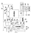
図1において、燃料電池システム(以下、単にシステムともいう)100は、一般家庭、または業務店、ビル等に設置される定置用であり、冷却液が流れる冷却通路を有する燃料電池のスタック1と、冷却液をスタック1の冷却通路10に流してスタック1を冷却する主冷却回路2と、これらを収容する収容室60をもつパッケージ6(筐体)とを有する。スタック1の膜電極接合体は、アノード(燃料極)およびカソード(酸化剤極)で挟持されたイオン伝導膜(例えば炭化フッ素系、炭化水素系等の固体高分子型、または、無機材料系の電解質膜)を有しており、シート型でも良いしチューブ型でも良い。アノードは触媒を有する。カソードは触媒を有する。触媒は白金等の貴金属系にできる。
(overall structure)
In FIG. 1, a fuel cell system (hereinafter also simply referred to as a system) 100 is for stationary installation in a general household, a business store, a building, or the like, and a fuel cell stack 1 having a cooling passage through which a coolant flows. The
図2に示すように、スタック1は、半導体スイッチ等のスイッチング素子53を介して放電負荷54(電力消費部)に接続されている。スタック1は、インバータ55およびブレーカ56(スイッチング部)を介して電力負荷57(家庭用電力負荷)に接続されている。電力負荷57はスタック1の電力または商用電源58の電力により作動される。プレーカ56に代えてリレーとしても良い。
As shown in FIG. 2, the stack 1 is connected to a discharge load 54 (power consumption unit) via a switching
本実施形態によれば、図1に示すように、主冷却回路2のうちスタック1の冷却通路10の出口10pから入口10iにかけて、出口温度センサ21、ヒータ29、第1熱交換器22、第1ポンプ23(第1搬送源)、アノード凝縮器24、入口温度センサ20が直列に設けられている。なお、ヒータ29は、スタック1の起動時等のように主冷却回路2を流れる冷却液の温度が過剰に低いときに、冷却液を暖めるものである。スタック1の定常運転時には、基本的には、ヒータ29はオフとされている。
According to the present embodiment, as shown in FIG. 1, the
第1ポンプ23が作動すると、主冷却回路2の冷却水は、アノード凝縮器24で受熱し、入口温度センサ20を経て、スタック1の入口10iから冷却通路10に流れ、スタック1から受熱し、冷却通路10を経て出口10pから吐出され、更に温度センサ21、ヒータ29、第1熱交換器22を順に流れる。このため、スタック1が発電するときに発生した熱は、主冷却回路2の冷却水に回収される。更に、改質装置70で発生したアノードガスの熱はアノード凝縮器24を経て主冷却回路2の冷却水に回収される。なお、主冷却回路2の冷却水は電気伝導度が低い液体が採用されている。
When the
スタック1の燃料極であるアノードにアノードガス(例えば水素含有ガス等の燃料)を供給するアノードガス供給系7について説明する。アノードガス供給系7は、改質部70aと改質部70aを改質反応に適するように加熱するバーナ71とをもつ改質装置70と、バーナ71に燃焼用空気を供給する空気ポンプ72(燃焼用空気搬送源)と、改質部70aおよびバーナ71に燃料(天然ガス等の炭化水素系ガス)を供給する燃料ポンプ73(燃料搬送源)と、改質装置70の蒸発部に改質水(純水)を供給する水ポンプ74(改質水搬送源)と、改質装置70の出口70pとスタック1のアノード入口とをアノード凝縮器24およびアノード入口バルブ75を経て繋ぐアノードガス通路76(燃料通路)とを有する。
The anode
ここで、改質装置70で生成されたアノードガスは、アノードガス通路76を介してスタック1のアノード(燃料極)に供給される。改質装置70の出口側にはCO低減部77が設けられている。CO低減部77は、改質装置70で生成されたアノードガスに含まれているCOの濃度を式(1)のシフト反応により低減させるシフト反応を促進させる触媒を有するCOシフト部78と、COシフト部78を経たアノードガス含まれているCOを式(2)により酸化させてCOの濃度をさらに低減させる酸化反応を促進させる触媒を有するCO酸化部79とで形成されている。COは、スタック1の触媒の性能に影響を与えるので、好ましくない。なお、COシフト部78の温度を検知する温度センサ78tが設けられている。CO酸化部79の温度を検知する温度センサ79tが設けられている。
式(1)…CO+H2O→H2+CO2(発熱反応)
式(2)…CO+1/2O2→CO2(発熱反応)
スタック1の酸化剤極であるカソードにカソードガス(例えば空気等の酸素含有ガス等の酸化剤ガス)を供給するカソードガス供給系8について説明する。カソードガス供給系8は、スタック1のカソードの入口に繋がるカソードガス通路80(酸化剤通路)と、カソードガス通路80に設けられたポンプ81(カソードガス搬送源)、加湿器82とを有する。加湿器82は、加湿路82aと、吸湿路82bと、加湿路82aおよび吸湿路82bを仕切る水分保持部材82cとを有する。ポンプ81が作動すると、カソードガスは加湿器82の加湿路82aで加湿された後、スタック1のカソード(酸化剤極)に供給される。
Here, the anode gas generated by the
Formula (1): CO + H 2 O → H 2 + CO 2 (exothermic reaction)
Formula (2): CO + 1 / 2O 2 → CO 2 (exothermic reaction)
A cathode
図1に示すように、スタック1のカソードの入口側を開閉するためのカソード入口バルブ85(カソード用の入口開閉部)が、カソードガス通路80に設けられている。スタック1のカソードの出口側を開閉するためのカソード出口バルブ87(カソード用の出口開閉部)が、カソードオフガス通路96に設けられている。
As shown in FIG. 1, a cathode inlet valve 85 (cathode inlet opening / closing portion) for opening and closing the cathode inlet side of the stack 1 is provided in the
アノードオフガス排出系90について説明する。オフガスとは、スタック1において発電反応に使われずに残留した余剰ガスという意味である。図1に示すように、アノードオフガス排出系90は、スタック1のアノードのアノード出口とバーナ71とを繋ぐアノードオフガス通路91と、アノードオフガス通路91に設けられたアノード出口バルブ92と、アノードオフガス通路91に設けられたアノードオフガス凝縮器93とを有する。ここで、スタック1のアノード出口から排出されたアノードオフガスは可燃成分を含むため、吸湿路82bおよびアノードオフガス凝縮器93で水分を低下させた後、バーナ71に供給され、燃焼される。
The anode off
カソードオフガス排出系95について説明する。図1に示すように、カソードガス排出系95は、スタック1のカソード出口から排出されたカソードオフガスを加湿器82の吸湿路82bを経て流すカソードオフガス通路96と、カソードオフガス通路96に設けられたカソードオフガス凝縮器97とを有する。ここで、スタック1のカソード出口から排出されたカソードオフガスは、加湿器82の吸湿路82bおよびカソードオフガス凝縮器97で水分を更に低下させ、排気される。
The cathode
図1に示すように、排熱回収系120は、第2ポンプ122(水搬送源)、アノードオフガス凝縮器93、カソードオフガス凝縮器97、燃焼排気熱交換器125、第2熱交換器127を経て循環する循環回路128を有する。第2ポンプ122が作動すると、循環回路128を冷却水(冷媒)が循環し、アノードオフガス凝縮器93、カソードオフガス凝縮器97、燃焼排気熱交換器125の熱が回収される。これにより循環回路128を流れる冷却水が加熱される。
As shown in FIG. 1, the exhaust
貯湯系130について説明する。図1に示すように、貯湯系130は、温水を貯留する貯湯槽131と、貯湯槽131の吐出口と貯湯槽131の吸入口とを繋ぐ貯湯回路132と、貯湯回路132に順に配置された第3ポンプ133(水搬送源)、第2熱交換器127、第1熱交換器22とを有する。第3ポンプ133が作動すると、貯湯回路132を流れる水が第2熱交換器127および第1熱交換器22を経て加熱される。すなわち、排熱回収系120で回収された熱は、第2熱交換器127により貯湯回路132の温水として回収される。主冷却回路2で回収された熱は第1熱交換器22により貯湯回路132の温水として回収される。制御部5は、ポンプ23、122、133、81、72、73、74、バルブ75、92、85、87、102、ヒータ29をそれぞれ制御する制御信号を出力する。
The hot
発電運転時には、スタック1のアノードおよびカソードが電気通路を介して電気的に結線された状態で、水素を含むアノードガスがアノードに供給され、酸素を含むカソードガスがカソードに供給され、次のような発電反応が発生する。アノードの発電反応で発生した電子(e−)は、電力通路を介してカソードに流れ、カソード反応に寄与する。カソード反応では水が生成される。
アノードの発電反応…H2→2H++2e−
カソードの発電反応…2H++1/2O2+2e−→H2O
(要部説明)
さて本実施形態の要部について説明する。まず、システムの運転の起動時について説明する。システムの運転の起動開始前においては、カソード入口バルブ85およびカソード出口バルブ87は閉鎖されており、スタック1のカソードは封止されている。同様にアノード入口バルブ75およびアノード出口バルブ92は閉鎖されており、スタック1のアノードは封止されている。
During power generation operation, with the anode and cathode of the stack 1 being electrically connected via an electrical path, an anode gas containing hydrogen is supplied to the anode and a cathode gas containing oxygen is supplied to the cathode as follows. Power generation reaction occurs. Electrons (e − ) generated by the power generation reaction at the anode flow to the cathode through the power path and contribute to the cathode reaction. The cathode reaction produces water.
Anode power generation reaction ... H 2 → 2H + + 2e −
Cathode power generation reaction 2H + + 1 / 2O 2 + 2e − → H 2 O
(Part explanation)
Now, the main part of this embodiment will be described. First, a description will be given of the start of system operation. Before the start of system operation, the
システムの運転の起動時において、制御部5は、カソード入口バルブ85およびカソード出口バルブ87を閉鎖した状態で、空気ポンプ72を作動させて燃焼用空気をバーナ71に供給し、アノード入口バルブ75およびアノード出口バルブ92を開放させる。次に燃料ポンプ73を作動させてガス状の改質用燃料を改質装置70に、ガス状の燃焼用燃料(改質用燃料とおなじもの)をバーナ71に供給する。これによりバーナ71に供給された燃料が燃焼し、改質装置70が改質反応に適するように高温に加熱される。その後、制御部5は、水ポンプ74を作動させて改質水を改質装置70に供給する。この結果、改質装置70において、炭化水素系の改質用燃料が水蒸気改質される。よって、水素を主要成分として含むアノードガスが改質装置70において生成される。ここで、アノード入口バルブ75およびアノード出口バルブ92は開放されている。このため、アノードガスはスタック1のアノードに積極的に供給される。このとき、カソード入口バルブ85およびカソード出口バルブ87は閉鎖され、カソードは封止されている。このため、起動時において、スタック1のカソードに存在する酸素のモル比は、化学量論的に、スタック1のアノードに連続的に供給される水素のモル比に比較して遙かに少ない。
At the start of operation of the system, the
上記したように燃料電池システムの運転の起動時において、制御部5は、第1制御を実施し、アノードガスをスタック1のアノードに供給させる。しかしながらシステムの起動時には、アノードガスの組成は必ずしも安定しておらず、CO濃度が高いことがあるので、アノードガスをスタック1のアノードに供給させて発電反応を発生させることは、好ましくない。
As described above, at the start of operation of the fuel cell system, the
そこで本実施形態によれば、システムの起動時の第1制御において、スタック1のアノードにアノードガスを積極的に供給させるものの、スタック1のカソードのカソード入口バルブ85およびカソード出口バルブ87を閉鎖し、カソードを封止させた状態とする。この結果、第1制御において、スタック1のアノードに連続的に供給される水素のモル数に比較して、スタック1のカソードの内部における酸素のモル数は、化学量論的に、大幅に低減または欠乏された状態とされる。この結果、第1制御において、スタック1における発電反応が抑制される。故に、スタック1の触媒がCO被毒することが抑えられる。
Therefore, according to the present embodiment, the anode gas is positively supplied to the anode of the stack 1 in the first control at the time of starting the system, but the
なお、スタック1が発電していない限り、COを含むアノードガスがスタック1のアノードに供給されたとしても、スタック1の触媒のCO被毒は抑制される。これに対して、スタック1が発電している場合には、COを含むアノードガスがスタック1のアノードに供給されるとき、スタック1の触媒のCO被毒の影響は増大し易い。 Note that, as long as the stack 1 is not generating power, even if an anode gas containing CO is supplied to the anode of the stack 1, CO poisoning of the catalyst of the stack 1 is suppressed. On the other hand, when the stack 1 is generating electric power, when the anode gas containing CO is supplied to the anode of the stack 1, the influence of the CO poisoning of the catalyst of the stack 1 tends to increase.
上記した本実施形態によれば、システムの起動時にスタック1の入口からアノードに供給されたアノードガスは、スタック1における発電反応にほとんど寄与せずに、アノード出口バルブ92を経てアノードオフガス通路91にそのまま流出され、更に、アノードオフガス凝縮器93で水分を低下させ、その後、改質装置70のバーナ71に供給され、バーナ71で燃焼用空気により燃焼される。
According to the above-described embodiment, the anode gas supplied to the anode from the inlet of the stack 1 at the time of starting the system hardly contributes to the power generation reaction in the stack 1 and passes through the
なお、スタック1のアノードを迂回させるようにアノードガス通路76とアノードオフガス通路91とを連通させる迂回通路を形成させる方式も考えられる。この方式によれば、改質装置70で生成されたアノードガスを迂回通路を通過させることによりスタック1のアノードを迂回させつつ、アノードオフガス通路91に流出させ、アノードオフガス凝縮器93で水分を低下させた後に、バーナ71に供給し、バーナ71で燃焼用空気により燃焼させる方式となる。しかしこの方式では、迂回通路が必要とされ、更に迂回通路を開閉させる迂回バルブが必要とされるおそれがあり、コストアップ、配管の複雑化が誘発される。この点本実施形態によれば、迂回通路、迂回通路を開閉させる迂回バルブを廃止することができる利点が得られる。
It is also conceivable to form a bypass passage that connects the
本実施形態によれば、システムの起動時において改質装置70の温度が安定すると、改質装置70で生成されるアノードガスの組成の安定性も向上し、アノードガスに含まれるCO濃度が低下する。そこで制御部5は、第1制御から第2制御に移行し、カソード入口バルブ85およびカソード出口バルブ87を開放させるとともに、ポンプ81を作動させてスタック1のカソードにカソードガスを供給させる。このとき、アノードガスはスタック1のアノードに供給されている。このように第2制御においては、制御部5は、スタック1に要請されている発電量に応じたカソードガスの流量をスタック1のカソードに供給する。これにより第2制御においてスタック1は良好に発電する。この場合、前述したようにアノードガスの組成の安定性が向上し、CO濃度が低下しているため、スタック1のアノードの触媒のCO被毒が抑制される。
According to the present embodiment, when the temperature of the
なお、本実施形態によれば、システムの起動時において、アノードガスを迂回させることなく、スタック1の入口からアノードに積極的に供給させることにしている。このため起動時間が長い場合には、スタック1の膜電極接合体におけるイオン伝導膜の水分が低減され、イオン伝導膜のプロトン伝導率が低下するおそれがあるときがある。しかし、改質装置40における水蒸気改質で生成されたアノードガスは、水蒸気を含むため、特に問題がない。 Note that, according to the present embodiment, the anode gas is actively supplied from the inlet of the stack 1 to the anode without detouring at the time of starting the system. For this reason, when the start-up time is long, the moisture of the ion conductive membrane in the membrane electrode assembly of the stack 1 may be reduced, and the proton conductivity of the ion conductive membrane may be lowered. However, since the anode gas generated by the steam reforming in the reformer 40 contains steam, there is no particular problem.
(実施形態2)
本実施形態は実施形態1と基本的には同様の構成、同様の作用効果を有するため、図1および2を準用する。システムの起動時において、CO低減部77の温度は必ずしも充分ではなく、CO低減部77の暖機に時間が必要である。CO低減部77の暖機完了前では、改質装置70の温度の安定性も必ずしも充分ではなく、加えて、CO低減部77の温度が低いため、CO低減部77におけるCO低減作用は充分ではないおそれがある。この場合、システムの起動時において、アノードガスに含まれるCO濃度が高いおそれがある。
(Embodiment 2)
Since this embodiment basically has the same configuration and the same function and effect as those of the first embodiment, FIGS. 1 and 2 are applied mutatis mutandis. At the time of starting the system, the temperature of the
これに対して、CO低減部77の暖機が完了した後では、CO低減部77の温度が高いため、CO低減部77の触媒活性温度領域となっており、CO低減部77におけるCO低減作用が良好であり、CO低減部77を通過したアノードガスに含まれるCO濃度が低い。そこで、制御部5は、CO低減部77の暖機完了前(アノードに供給されるアノードガスに含まれているCO濃度が(所定値よりも)高いおそれがあるとき)において、カソードを酸素低減状態とした上記した第1制御を実行し、スタック1の発電反応を制限する。
On the other hand, after the warming-up of the
これに対して、CO低減部77の暖機完了後(アノードに供給されるアノードガスに含まれているCO濃度が低い(所定値以下)と考えられるとき)においては、制御部5は、カソードを開放状態とした第2制御を実施し、スタック1の発電反応を促進させる。
On the other hand, after the warming-up of the
更に説明を加える。すなわち、システムの運転の起動開始前において、第1制御では、カソード入口バルブ85およびカソード出口バルブ87は閉鎖され、カソードは封止されている。同様に、アノード入口バルブ75およびアノード出口バルブ92は閉鎖され、アノードは封止されている。
Further explanation will be added. That is, before starting the operation of the system, in the first control, the
システムの運転の起動時において、CO低減部77の暖機完了前では、制御部5は、カソード入口バルブ85およびカソード出口バルブ87を閉鎖し、カソードを封止した状態で、制御部5は、前述したように、空気ポンプ72を作動させて燃焼用空気をバーナ71に供給し、アノード入口バルブ75およびアノード出口バルブ92を開放させ、燃料ポンプ73を作動させて改質用燃料を改質装置70に、燃焼用燃料をバーナ71に供給する。これによりバーナ71に供給された燃焼用燃料が燃焼するので、改質装置70が改質反応に適するように高温に加熱される。その後、制御部5は、水ポンプ74を作動させて改質水を改質装置70に供給する。この結果、改質装置70において、ガス状をなす炭化水素系の改質用燃料が水蒸気改質され、水素を主要成分として含むアノードガス(水素含有ガス)が生成される。ここで、アノード入口バルブ75およびアノード出口バルブ92は開放されている。このため、アノードガスはスタック1のアノードを迂回することなく、アノードに供給される。このとき、前述したように、カソード入口バルブ85およびカソード出口バルブ87は閉鎖されているためカソードガスの進入が抑えられ、結果として、スタック1のカソードにおける酸素濃度は、カソードガスが本来有する酸素濃度よりも低減された状態に維持されている。
At the start of operation of the system, the
上記したように燃料電池システムの運転の起動時において、制御部5は、第1制御を実施し、スタック1のアノードにアノードガスを積極的に供給させる。システムの起動時には、アノードガスの組成は必ずしも安定していないので、CO濃度が高くなるおそれがあり、スタック1のアノードに供給させて発電反応を積極的に発生させることは、好ましくない。
As described above, at the start of operation of the fuel cell system, the
そこで本実施形態によれば、システムの起動時に、スタック1のアノードにアノードガスが積極的に供給されるものの、スタック1のカソードのカソード入口バルブ85およびカソード出口バルブ87が閉鎖され、カソードが封止された状態とされている。すなわち、スタック1のカソードにおける酸素濃度は、カソードガス(空気)が本来有する酸素濃度よりも低減されている。このためシステムの起動時には、アノードに供給されるアノードガスに含まれている水素のモル数に比較して、カソードの内部における酸素のモル数は、化学量論的に、大幅に低減または欠乏された状態とされている。この結果、システムの起動時において、スタック1における発電反応が大幅に制限される。従ってアノードの触媒のCO被毒が抑制される。
Therefore, according to the present embodiment, when the system is started, anode gas is actively supplied to the anode of the stack 1, but the
このため、スタック1の入口からアノードに供給されたアノードガスは、発電反応を発生にあまり寄与せず(すなわち、水素濃度をあまり減少させることなく)、アノード出口バルブ92を経てアノードオフガス通路91にそのまま流出され、そして、アノードオフガス凝縮器93で余剰の水分を低下させた後に、バーナ71に供給され、バーナ71で燃焼用空気により燃焼される。
For this reason, the anode gas supplied to the anode from the inlet of the stack 1 does not contribute much to generation of a power generation reaction (that is, does not significantly reduce the hydrogen concentration), and passes through the
上記した本実施形態によれば、システムの起動時に時間が経過すると、改質装置70の昇温温度が安定する他に、CO低減部77の昇温温度も安定し、CO低減部77の暖機も完了する。すなわち、CO低減部77の暖機完了後では、改質装置70およびCO低減部77の温度が上昇し、改質装置70の触媒およびCO低減部77の触媒が活性し、改質装置70およびCO低減部77におけるCO低減作用が良好となり、アノードガスに含まれるCO濃度が大幅に低下する。
According to the above-described embodiment, when the time elapses when the system is started, the temperature rising temperature of the
そこで制御部5は、上記した第1制御から第2制御に移行する。第2制御では、アノード入口バルブ75およびアノード出口バルブ92の開放が維持されつつ、カソード入口バルブ85およびカソード出口バルブ87が開放される。更に、ポンプ81が作動しスタック1のカソードにカソードガス(空気)が供給される。これにより制御部5は、スタック1に要請される発電量に応じて、カソードガスをスタック1のカソードに供給し、スタック1で発電する。
Therefore, the
このような本実施形態によれば、前記した実施形態と同様に、システムの起動時においてアノードガスがスタック1を迂回させる必要がない。よって迂回通路、迂回通路を開閉させる迂回バルブを廃止させることができる利点が得られる。 According to the present embodiment as described above, it is not necessary for the anode gas to bypass the stack 1 when the system is started up, as in the above-described embodiment. Therefore, there is an advantage that the bypass passage and the bypass valve for opening and closing the bypass passage can be eliminated.
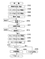
図3は、システムの起動時において制御部5が実施する制御のフローチャートの一例を示す。フローチャートはこれに限定されるものではない。まず、燃料電池システムの運転の起動時について説明する。前述したようにシステムの運転の起動を開始させる前の状態において、カソード入口バルブ85およびカソード出口バルブ87は閉鎖され、カソードは封止されている。この場合、カソードは酸素欠乏状態であることが好ましい。アノード入口バルブ75およびアノード出口バルブ92は閉鎖され、アノードは封止されている。
FIG. 3 shows an example of a flowchart of the control performed by the
先ず、システムの起動運転が指令されていれば、制御部5は、第1制御として、空気ポンプ72を作動させて燃焼用空気をバーナ71に供給し、更に、着火用のグロー放電器に通電させ(ステップS102)、その後、制御部5はアノード入口バルブ75およびアノード出口バルブ92を開放させる(ステップS104,S106)。更に、燃料ポンプ73を作動させ、ガス状をなす改質用燃料を改質装置70に供給し、且つ、ガス状をなす燃焼用燃料をバーナ71に供給する(ステップS108)。これによりバーナ71が着火され、バーナ71に供給された燃料が燃焼するので、改質装置70が改質反応に適するように高温に加熱される。
First, if the start-up operation of the system is instructed, the
更に、制御部5は、改質装置70が蒸気発生準備完了か否か判定する(ステップS110)。改質装置70が昇温しており、蒸気発生準備完了であれば(ステップS110のYES)、制御部5は、水ポンプ74を作動させて改質水を改質装置70に供給する(ステップS112)。この結果、改質装置70において、炭化水素系の改質用燃料が水蒸気改質され、水素を主要成分として含むアノードガスが生成される。このとき、カソードは封止されているものの、アノード入口バルブ75およびアノード出口バルブ92は既に開放されているため、アノードガスはスタック1のアノードに供給される(第1制御)。
Furthermore, the
制御部5は、CO低減部77の暖機が完了したか否かを、すなわち、CO低減部77が所定温度以上か否かを温度センサ78t,79tにより判定する(ステップS114)。温度センサ78t,79tの少なくとも一方の温度が所定温度以上であれば暖機完了であり、所定温度未満であれば暖機完了前である。CO低減部77の昇温が充分ではなく、CO低減部77の暖機が完了していなければ(ステップS114のNO)、制御部5は、アノードガスをスタック1のアノードに供給させつつ、CO低減部77の暖機完了するまで第1制御を実施しつつ待機する。
The
上記した第1制御においては、アノード入口バルブ75およびアノード出口バルブ92が開放されているため、改質装置70で生成されたアノードガスはスタック1のアノードに供給される。しかしながらカソード入口バルブ85およびカソード出口バルブ87は閉鎖されているため、前述したように発電反応は制限される。故に、アノードガスはあまり発電反応に寄与せず、アノードオフガス通路91からバーナ71に供給され、バーナ71で燃焼される。
In the first control described above, since the
ステップS114における判定の結果、CO低減部77の暖機が完了していれば(ステップS114の完了)、CO低減部77を通過したアノードガスに含まれているCO濃度は良好に低下する(例えば10ppm以下)。そこで制御部5は、第1制御から第2制御に移行すべく、カソード入口バルブ85を開放させ(ステップS116)、カソード出口バルブ87を開放させる(ステップS118)。次にポンプ81を作動させて(ステップS120)、カソードガスをスタック1のカソードに供給させる。上記したステップS102〜ステップS122までの間において、スタック1のアノードおよびカソードは電力負荷57に電気的に接続されていない開回路状態である。
If the result of determination in step S114 is that the warming-up of the
なお、制御部5はOCVの値を判定し、OCVの値が過剰に低ければシステムが異状であるため、システムを停止する(ステップS126)。OCVの値が所定値よりも高ければ、制御部5は、スタック1と電力負荷57とを電気的に接続し、すなわち、スタック1のアノードおよびカソードを電力負荷57を介して電気的に接続し、システムの発電運転を開始させ(ステップS124)、メインルーチンにリターンする。
Note that the
(実施形態3)
本実施形態は実施形態1,2と基本的には同様の構成、同様の作用効果を有するため、図1および図2を準用する。本実施形態によれば、システムの運転の停止時において、制御部5は、スタック1と電力負荷54とを電気的に遮断させスタック1を開回路とした状態で、アノード入口バルブ75およびアノード出口バルブ92を開放させスタック1のアノードにアノードガスを供給させつつ、カソード入口バルブ85およびカソード出口バルブ87を閉鎖してカソードのカソードガス(空気)を封止させる。
(Embodiment 3)
Since this embodiment basically has the same configuration and the same operation and effect as those of the first and second embodiments, FIGS. 1 and 2 are applied mutatis mutandis. According to the present embodiment, when the system operation is stopped, the
このとき、スタック1のOCVが次第に高くなる可能性がある。この状態において、OCVの値が所定電圧値よりも過剰に高くなると、制御部5は、放電用のスイッチング素子53をオンし、スタック1と放電負荷54とを電気的に繋ぐ。これにより、スタック1で発生する電力を放電負荷54(電力消費部)で積極的に放電させて消費させる。これによりスタック1のOCVの値の過剰な上昇が抑制される。更に放電時にはスタック1の発電反応が進行するため、カソードの内部の酸素は電力消費前よりも低減されて消耗される。
At this time, the OCV of the stack 1 may gradually increase. In this state, when the value of OCV becomes excessively higher than the predetermined voltage value, the
換言すると、放電負荷54で放電させているときには、制御部5は、アノード入口バルブ75およびアノード出口バルブ92を開放させて、スタックのアノードにアノードガスを積極的に供給させている。このため、カソードの内部の酸素濃度は、アノードの内部の水素濃度よりも低減されて消耗される。このためシステムの停止時において、スタック1のカソードでは、酸素欠乏状態(酸素低減状態)、つまり、窒素ガスの富化状態が良好に形成される。
In other words, when discharging is performed by the
上記したようにシステムの停止時において、スタック1のカソードで酸素欠乏状態(酸素低減状態,窒素富化状態)が形成されたら、制御部5は、スイッチング素子53をオフとし、放電負荷54による放電を停止させると共に、アノード入口バルブ75およびアノード出口バルブ92を閉鎖させてアノードにアノードガス(水素含有ガス)を封止させる。このとき、カソード入口バルブ85およびカソード出口バルブ87の閉鎖状態は、システムの次の起動まで維持される。このため、カソードにおける酸素欠乏状態(窒素富化状態)は、システムの次の起動まで良好に維持される。
As described above, when an oxygen-deficient state (oxygen-reduced state, nitrogen-enriched state) is formed at the cathode of the stack 1 when the system is stopped, the
更に、上記した本実施形態によれば、システムを起動させるときには、制御部5は、前記した実施形態1,2と同様に実施できる。すなわち、本実施形態によれば、システムの前回の停止時においてカソードの酸素欠乏状態(窒素富化状態)が形成され、システムの次の起動まで維持される。この結果、システムを次に起動させるとき、制御部5は、改質装置70が作動している状態において、アノード入口バルブ75およびアノード出口バルブ92を開放させてスタック1のアノードにアノードガスを積極的に供給させる。このとき、制御部5は、スタック1のカソードのカソード入口バルブ85およびカソード出口バルブ87を閉鎖させた状態とし、カソードにおける酸素欠乏状態(窒素富化状態)を維持させる。このため、システムの起動時において、スタック1のアノードに供給されるアノードガスに含まれている水素のモル数に比較して、スタック1のカソードの内部における酸素のモル数は、大幅に欠乏された状態とされ、スタック1における発電反応が制限される。
Furthermore, according to the above-described embodiment, when the system is activated, the
この結果、システムの起動時には、COを含むおそれがあるアノードガスがスタック1のアノードに積極的に供給されたとしても、スタック1における発電反応がほとんど発生せず、アノードの触媒のCO被毒が抑制される。すなわち、アノードガスは、発電反応をほとんど発生させることなく、アノード出口バルブ92を経てアノードオフガス通路91にそのまま流出され、吸湿路82bおよびアノードオフガス凝縮器93で水分を低下させた後、バーナ71に供給され、バーナ71で燃焼用空気により燃焼される。
As a result, even when an anode gas that may contain CO is positively supplied to the anode of the stack 1 at the time of starting the system, the power generation reaction in the stack 1 hardly occurs, and CO poisoning of the catalyst of the anode does not occur. It is suppressed. That is, the anode gas flows out as it is to the anode off-
以上説明したように本実施形態においても、上記したようにシステムの起動時には、制御部5は実施形態1,2と同様な制御を実施する。すなわち、スタック1の入口からアノードに供給されたCOを含むおそれがあるアノードガスは、発電反応にほとんど寄与せず、アノードの触媒のCO被毒が抑制される。更にアノードガスは、アノード出口バルブ92を経てアノードオフガス通路91に流出され、アノードオフガス凝縮器93で水分を低下させた後、バーナ71に供給され、バーナ71で燃焼用空気により燃焼される。
As described above, also in the present embodiment, as described above, the
本実施形態においても、前記した実施形態1,2と同様に、迂回通路および迂回バルブを廃止できる利点が得られる。
Also in this embodiment, the advantage which can abolish a bypass path and a bypass valve similarly to
図4は、システムの停止時において、制御部5が実施する制御のフローチャートの一例を示す。フローチャートはこれに限定されるものではない。すなわち、システムの運転の停止させるとき、制御部5は、スタック1を通常運転状態から最低負荷状態(最低発電量)に移行させる(ステップS202)。すなわち、制御部5は、燃料ポンプ73,水ポンプ74,ポンプ81の単位時間あたりの回転数(駆動量)を低減させ、アノードガスおよびカソードガスの単位時間あたりの流量を少なく抑える。更に、発電停止指令を出力し、電力負荷57とスタック1との電気的接続を遮断させる(ステップS204)。この場合、OCVが過剰に高くなるおそれがある。
FIG. 4 shows an example of a flowchart of control executed by the
更に、制御部5は、改質装置70に供給する改質用燃料および改質水を最低限とし、改質装置70を改質運転から最低負荷運転へ移行させる(ステップS206)。最低負荷運転ではアノードガスは流量が低下するものの、まだ生成される。)
次に、制御部5は、カソード出口バルブ87を閉鎖させ(ステップS208)、所定時間待機し(ステップS210)、その後、カソード入口バルブ85を閉鎖させる(ステップS212)、カソードを封止させる。その後、制御部5はポンプ81の作動を停止させ、カソードガスの供給を停止させる(ステップS214)。このような順番でバルブが閉鎖されれば、カソードにカソードガスができるだけ封入され、カソードに封入されているカソードガスの圧力はできるだけ高めにされ、ひいてはカソードの過剰な負圧化が抑制または防止される。よってスタック1の耐負圧性設計が容易となる利点が挙げられる。
Further, the
Next, the
アノード入口バルブ75およびアノード出口バルブ92は開放され、改質装置70は暖機運転しているため、改質装置70で生成されたアノードガスがスタック1のアノードに供給されている。ここでスタック1のカソードにカソードガス(空気)が残留しており、且つ、電力負荷57とスタック1との電気的接続が遮断されているため、スタック1のOCVが過剰に上昇するおそれがある。そこでOCVの値Vcが第1所定値Vx(例えば0.3ボルト)未満か否か判定する(ステップS216)。第1所定値Vxは、システムの種類、スタック1の触媒の材質等に応じて適宜設定できる。OCVの値Vcが第1所定値Vx(例えば0.3ボルト)を高圧側に超えていれば(ステップS216のNO)、制御部5はスイッチング素子53をオンしてスタック1と放電負荷54とを電気的に接続させ、スタック1の電力を放電負荷54で放電させて消費させる(ステップS218)。これによりOCVの過剰な上昇が抑制され、スタック1の触媒の電気化学的な劣化が抑えられる。
Since the
上記したように放電が実施されるとき、スタック1のアノードおよびカソードにおける発電反応は進行するため、封止状態のカソードの内部の酸素濃度は電力消費前よりも低減され、カソードは酸素欠乏状態(窒素富化状態)に良好に設定される。 When the discharge is performed as described above, the power generation reaction in the anode and cathode of the stack 1 proceeds. Therefore, the oxygen concentration inside the cathode in the sealed state is reduced as compared with that before power consumption, and the cathode is in an oxygen-deficient state ( Nitrogen-rich state) is set well.
ステップS216における判定の結果、OCVの値Vcが第1所定値Vx(例えば0.3ボルト)未満であれば(ステップS216のYES)、制御部5は、改質装置70の最低負荷運転を停止させ、水ポンプ74および燃料ポンプ73の作動を停止させる。これにより改質用燃料および改質水が改質装置70に供給されることは、停止される。なお、改質装置70の運転が停止されても、空気ポンプ72は作動しており、燃焼用空気が冷却空気として改質装置70に供給され、改質装置70の冷却が促進される。
If the result of determination in step S216 is that the OCV value Vc is less than the first predetermined value Vx (eg, 0.3 volts) (YES in step S216), the
更に、制御部5は、アノード入口バルブ75およびアノード出口バルブ92を閉鎖(ステップS222,S224)する。よってアノードガスがスタック1のアノードに供給されることは、停止される。ここで、停止している改質装置70の温度が所定温度よりも低下していれば(ステップS228のYES)、改質装置70の冷却を終了させるべく、空気ポンプ72の作動を停止し、燃焼用空気を冷却空気として改質装置70に供給することを停止し(ステップS230)、改質装置70の温度の冷却処理を終了させ、システムを停止させるべく、システムの補機の作動を停止させる(ステップS232)。
Further, the
さて本実施形態によれば、システムの停止時において、OCVの値Vcが第1所定値Vx(例えば0.3ボルト)を超えているとき、その信号が制御部5に入力され、制御部5は割り込み処理を実施する(図5)。従って図5に示すように、OCVの値Vcが第1所定値Vx(例えば0.3ボルト)を超えているとき、制御部5は、スイッチング素子53をオンしてスタック1と放電負荷54とを電気的に接続し、スタック1の電力を放電負荷54で放電させる(ステップS302)。放電時に、スタック1のアノードおよびカソードにおける発電反応は進行するため、カソードの内部の酸素濃度は電力消費前よりも低減される。よって、カソードは酸素欠乏状態(窒素富化状態)に設定される。
Now, according to the present embodiment, when the OCV value Vc exceeds the first predetermined value Vx (for example, 0.3 volts) when the system is stopped, the signal is input to the
制御部5は、OCVの値Vcが第1所定値Vx(例えば0.3ボルト)未満であるか否か判定し(ステップS304)、OCVの値Vcが第1所定値Vx(例えば0.3ボルト)未満であれば、スタック1と放電負荷54とを電気的に遮断させ、放電を中止する(ステップS306)。しかし時間経過につれてOCVが回復するおそれがある。このため、制御部5は所定時間待機し(ステップS308)、OCVの値Vcと第2所定値Vy(例えば0.5ボルト)とを比較し(ステップS310)、値Vcが第2所定値Vy以上であれば(ステップS310のNO)、制御部5はスイッチング素子53を再びオンし、スタック1と放電負荷54とを電気的に接続し、スタック1の電力を放電負荷54で再び放電させて消費させる(ステップS302)。ステップS310における判定の結果、OCVの値Vcが第2所定値Vy(例えば0.5ボルト)未満であれば(ステップS310のYES)、OCVは低いため、制御部5は、メインルーチンにリターンする。なお、第1所定値Vx、第2所定値Vyおよび所定時間は燃料電池システムに応じて適宜設定できる。
The
このように本実施形態によれば、システムの停止時に、スタック1と電力負荷57とが遮断された状態においてOCVの値Vcが過剰に上昇すると、スタック1と放電負荷54とが電気的に接続され、放電負荷54で放電が行われる。この結果、スタック1の発電反応が進行し、カソードの内部の酸素濃度は電力消費前よりも低減され、カソードは酸素欠乏状態(窒素富化状態)となる。このためシステムの停止時には、カソードは酸素欠乏状態(窒素富化状態)に設定される。
Thus, according to the present embodiment, when the OCV value Vc rises excessively in a state where the stack 1 and the
上記したようにカソード入口バルブ85およびカソード出口バルブ87の双方の閉鎖状態は、システムの次の起動まで維持される。このため、スタック1のカソードにおける酸素欠乏状態(窒素富化状態)は、システムの次の起動まで良好に維持される。
As described above, the closed state of both
以上説明したように本実施形態によれば、システムを起動させるときには、制御部5は、前記した実施形態1,2と同様に実施できる。すなわち、本実施形態によれば、システムの停止時において、制御部5は、スタック1のカソードにおける酸素欠乏状態(窒素富化状態)を積極的に形成する。制御部5は、カソード入口バルブ85およびカソード出口バルブ87の閉鎖状態を維持することにより、スタック1のカソードにおける酸素欠乏状態(窒素富化状態)を、システムの次の起動まで良好に維持する。この結果、システムを次に起動させるとき、制御部5は、アノード入口バルブ75およびアノード出口バルブ92を開放させ、COを含むおそれがあるアノードガスをスタック1のアノードに供給させるものの、スタック1のカソードは酸素欠乏状態(窒素富化状態)にシステムの次の起動時まで維持されている。この結果、システムの起動時において、アノードガスをスタック1のアノードに積極的に供給したとしても、スタック1における発電反応が抑制され、スタック1のアノードのCO被毒が抑制される。
As described above, according to the present embodiment, when starting the system, the
本実施形態においても、上記したようにシステムの起動時には、制御部5は実施形態1,2と同様な制御を実施する。すなわち、スタック1の入口からアノードに供給されたアノードガスは、スタック1における発電反応を発生させることなく、アノード出口バルブ92を経てアノードオフガス通路91に流出され、アノードオフガス凝縮器93で水分を低下させた後に、バーナ71に供給され、バーナ71で燃焼用空気により燃焼される。このようにシステムの起動時においてスタック1のアノードガスに供給されたアノードガスは、スタック1における発電反応を発生させることが抑えられるため、アノードにおける触媒のCO被毒が抑制される。
Also in the present embodiment, as described above, the
(実施形態4)
本実施形態は実施形態1,2,3と基本的には同様の構成、同様の作用効果を有するため、図1および図2を準用する。システムの運転の停止時において、制御部5は、カソード出口バルブ87を閉鎖し且つカソード入口バルブ85を開放した状態で、ポンプ81を作動させ、カソードガスをスタック1のカソードに供給する。その後、制御部5は、カソード出口バルブ87を閉鎖した状態で、カソード入口バルブ85を閉鎖させる。この結果、スタック1のカソードの内部は、カソードガス(空気)で満たされる。カソードの圧力は、大気圧を超える高圧としても良いし、大気圧程度でもよい。
(Embodiment 4)
Since this embodiment basically has the same configuration and the same function and effect as the first, second, and third embodiments, FIGS. 1 and 2 are applied mutatis mutandis. When the operation of the system is stopped, the
この場合、スタックのカソードにカソードガスが存在し、且つ、アノードにアノードガスが供給されている。このためスタック1のアノードとカカソードとが電気的に遮断されている場合には、スタック1のOCVが過剰に高くなるおそれがある。 In this case, the cathode gas is present at the cathode of the stack, and the anode gas is supplied to the anode. For this reason, when the anode and the cathode of the stack 1 are electrically cut off, the OCV of the stack 1 may become excessively high.
そこで制御部5は、スタック1のOCVが過剰に高くなると、前述したように、放電用のスイッチング素子53をオンし、スタック1と放電負荷54とを電気的に繋ぐ。この結果、スタックにおいて発生する電力を放電負荷54で積極的に放電させて消費させる。放電時によりOCVの過剰な上昇が抑制される。更に放電時にスタック1の発電反応が進行するため、カソードの内部の酸素は消耗され、カソードにおける酸素濃度は電力消費前よりも大幅に低減される。このように放電によりカソードの内部に残留する酸素は消費されるため、カソードにおいては、不活性の窒素ガスの濃度が高くなる。すなわち、スタック1のカソードの内部はほとんど窒素ガスとなる。本実施形態によれば、スタック1のOCVが過剰に高くなるたびに、放電用のスイッチング素子53がオンされ、放電負荷54が放電する。この結果、カソードの内部の酸素は消費され欠乏状態とされる。
Therefore, when the OCV of the stack 1 becomes excessively high, the
放電が所定回数実施されると、酸素が消費されるぶん、カソードの圧力は低下する。そこで、制御部5は、カソード出口バルブ87を閉鎖した状態でカソード入口バルブ85を開放し、ポンプ81を作動させ、カソードガス(空気)をスタック1のカソードに補充しても良い。この場合、ポンプ81の単位時間あたりの回転数(駆動量)を、システムの定常運転(定格運転)よりも高めることができるが、定常運転と同一でも良い。
When the discharge is performed a predetermined number of times, the cathode pressure drops as much as oxygen is consumed. Therefore, the
上記したように放電による酸素の消費と、カソードへのカソードガスの補充とを交互に所定回(複数回)ずつ実施することもできる。これによりカソードの内部を大気圧を超える高圧にすることができる。但し、カソードの内部は大気圧以下でも良い。 As described above, the consumption of oxygen by discharge and the replenishment of the cathode gas to the cathode can be alternately performed a predetermined number of times (a plurality of times). Thereby, the inside of a cathode can be made into the high voltage | pressure exceeding atmospheric pressure. However, the inside of the cathode may be under atmospheric pressure.
この状態で、システムの次の起動時まで、カソード入口バルブ85およびカソード出口バルブ87は閉鎖されている。このためカソードにおける酸素欠乏状態(窒素富化状態)は、システムの次の起動時まで良好に維持される。
In this state, the
上記したように本実施形態によれば、スタック1のカソードの内部の酸素濃度を欠乏させる制御を実施した後、カソードに封入されているガスは、実質的に窒素ガスとなる。よって、スタック1のカソードの内部は、窒素ガスが封入されている状態に相当する。この場合、外気がカソードに進入することを抑えることを考慮すると、カソードの圧力は、大気圧よりも高いことが好ましい。ポンプやバルブなどを考慮すると、カソードの圧力は例えば3気圧未満にできる。 As described above, according to the present embodiment, after the control for depleting the oxygen concentration inside the cathode of the stack 1 is performed, the gas sealed in the cathode is substantially nitrogen gas. Therefore, the inside of the cathode of the stack 1 corresponds to a state in which nitrogen gas is sealed. In this case, it is preferable that the pressure of the cathode is higher than the atmospheric pressure in consideration of suppressing the outside air from entering the cathode. Considering a pump, a valve, etc., the cathode pressure can be, for example, less than 3 atmospheres.
このようにカソードの内部は窒素富化状態とされているため。システムの停止から次の起動までの期間が長くなったとしても、酸素を含む外気がスタック1のカソードに進入することが効果的に抑制される。カソードの圧力が大気圧よりも高ければ、外気の進入が一層抑制される。よって、カソードにおける酸素欠乏状態(窒素富化状態)がシステムの次の起動時まで良好に維持される。 This is because the inside of the cathode is nitrogen-enriched. Even if the period from the stop of the system to the next start-up becomes longer, it is possible to effectively suppress the outside air containing oxygen from entering the cathode of the stack 1. If the pressure of the cathode is higher than atmospheric pressure, the entry of outside air is further suppressed. Therefore, the oxygen-deficient state (nitrogen-enriched state) at the cathode is well maintained until the next start-up of the system.
上記したようにシステムの停止が完了しているときには、カソードの圧力を大気圧(1気圧)以上とすることができるため、酸素を含む大気がカソードに進入することが抑えられる。よって、カソード出口バルブ87およびカソード入口バルブ85については、過剰なシール性が要請されず、安価なバルブを使用できる利点が挙げられる。勿論、高いシール性をもつ高価なバルブを使用しても良い。
As described above, when the system is stopped, the cathode pressure can be increased to atmospheric pressure (1 atm) or more, so that the atmosphere containing oxygen can be prevented from entering the cathode. Therefore, the
(実施形態5)
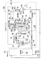
図6は、本実施形態は実施形態1〜4と基本的には同様の構成、同様の作用効果を有する。以下、相違する部分を中心として説明する。すなわち、図6に示すように、カソード出口バルブ87Bは、スタック1のカソードの出口側に設けられた逆止弁であり、加湿器82の吸湿路82bの上流に配置されている。逆止弁はコストの面で好ましい。カソード出口バルブ87Bは、スタック1のカソードから排出されるカソードオフガスをカソードから排出される方向(矢印W1方向)に流出させるものの、その逆の方向(矢印W2方向)の流れを阻止する。カソード出口バルブ87Bは、カソードオフガス通路96に連通する弁口870と、弁口870を閉鎖するための弁体872と、弁口870を弁体872で閉鎖する方向に付勢する付勢バネ874とを有する。付勢バネ874は、スタック1のカソードの内部を大気圧を超える圧力に維持することができるバネ力を有する。このためカソードガスの供給圧を高めれば、スタック1のカソードの内部を大気圧を超える圧力に維持できる。従って、システムの停止時から次の起動時までの間において、酸素を含む外気がカソード出口バルブ87Bからスタック1のカソードに進入することが抑えられる。この結果、カソード出口バルブ87Bが閉鎖されていれば、システムの停止時からシステムの次の起動時までの間において、スタック1のカソードの内部は、酸素欠乏状態(酸素低減状態)に良好に維持される。本実施形態においても、前記した実施形態と同様に、迂回通路、迂回通路を開閉させる迂回バルブを廃止することができる利点が得られる。
(Embodiment 5)
In FIG. 6, the present embodiment basically has the same configuration and the same function and effect as the first to fourth embodiments. Hereinafter, the description will focus on the different parts. That is, as shown in FIG. 6, the
(実施形態6)
図7は実施形態6を示す。本実施形態は実施形態1〜5と基本的には同様の構成、同様の作用効果を有する。以下、相違する部分を中心として説明する。カソード出口バルブ87Bは、スタック1のカソードの出口側に設けられた逆止弁である。カソード出口バルブ87Bの付勢バネ874は、スタック1のカソードの内部を大気圧を超える圧力に維持することができるバネ力を有する。カソード出口バルブ87Bは加湿器82の吸湿路82bの下流に配置されている。スタック1から排出されたカソードオフガスは多量の水蒸気を含む。カソードオフガスの水蒸気は吸湿路82bで低減される。このため、カソード出口バルブ87Bを通過するカソードオフガスの水蒸気量が低減される。よってカソード出口バルブ87Bのバルブ径が小さくでき、バルブ87Bが小型化される利点が得られる。
(Embodiment 6)
FIG. 7 shows a sixth embodiment. This embodiment has basically the same configuration and the same function and effect as the first to fifth embodiments. Hereinafter, the description will focus on the different parts. The
(実施形態7)
図8は実施形態7を示す。本実施形態は実施形態1〜6と基本的には同様の構成、同様の作用効果を有する。以下、相違する部分を中心として説明する。図8に示すように、カソード出口バルブ87Bは、スタック1のカソードの出口側において、加湿器82の吸湿路82bの下流に配置されている。カソードガスをスタック1のカソードに供給するためのポンプ81(カソードガス搬送源)がスタック1のカソードの入口側に設けられている。カソード入口バルブ85Dはポンプ81に組み込まれている。この結果、システムの停止から次に起動するまでの間において、カソード入口バルブ85Dが閉鎖されていれば、酸素を含む外気がスタック1の入口からカソードに進入することが抑えられる。この結果、システムの停止時から次の起動時までの間において、スタック1のカソードの内部は、酸素欠乏状態(窒素富化状態)に良好に維持される。窒素富化状態とは、空気の窒素濃度よりも高い窒素濃度の状態をいう。本実施形態においても、前記した実施形態と同様に、迂回通路、迂回通路を開閉させる迂回バルブを廃止することができる利点が得られる。
(Embodiment 7)
FIG. 8 shows a seventh embodiment. The present embodiment has basically the same configuration and the same function and effect as the first to sixth embodiments. Hereinafter, the description will focus on the different parts. As shown in FIG. 8, the
(実施形態8)
図9は実施形態8を示す。本実施形態は実施形態1〜8と基本的には同様の構成、同様の作用効果を有する。改質装置70の出口側にはCO低減部77Bが設けられている。CO低減部77Bは、COシフト部78とメタネーション反応部79Bとで形成されている。COシフト部78は、前述同様に、改質装置70で生成されたアノードガスに含まれているCOの濃度を式(1)のシフト反応により低減させる。メタネーション反応部79Bは、COシフト部78を経たアノードガスに含まれているCOをH2とのメタネーション反応によりメタン化させることにより、COの濃度をさらに低減させる。COは、スタック1の触媒の性能に影響を与えるので、好ましくない。
メタネーション反応…CO+3H2→CH4+H2O(発熱反応)
本実施形態においても、前記した実施形態と同様に、迂回通路、迂回通路を開閉させる迂回バルブを廃止することができる利点が得られる。
(Embodiment 8)
FIG. 9 shows an eighth embodiment. This embodiment has basically the same configuration and the same function and effect as the first to eighth embodiments. A
Methanation reaction… CO + 3H 2 → CH 4 + H 2 O (exothermic reaction)
Also in this embodiment, similarly to the above-described embodiment, there is an advantage that the bypass passage and the bypass valve for opening and closing the bypass passage can be eliminated.
(実施形態9)
図10は実施形態9を示す。本実施形態は実施形態1と基本的には同様の構成、同様の作用効果を有する。改質装置70の出口側にはCO低減部77Cが設けられている。CO低減部77Cは、改質装置70で生成されたアノードガスに含まれているCOの濃度をメタネーション反応により低減させる第1メタネーション反応部78Cと、第1メタネーション反応部78Cを経たアノードガスに含まれているCOをH2とのメタネーション反応によりメタン化させてCOの濃度をさらに低減させる第2メタネーション反応部79Cとで形成されている。本実施形態によれば、前記した実施形態と同様に、迂回通路、迂回通路を開閉させる迂回バルブを廃止することができる利点が得られる。
(Embodiment 9)
FIG. 10 shows a ninth embodiment. This embodiment has basically the same configuration and the same function and effect as the first embodiment. A
(実施形態10)
本実施形態は実施形態1と基本的には同様の構成、同様の作用効果を有するため、図1および図2を準用する。システムの起動時において、アノードガスを迂回させることなく、スタック1の入口からアノードに積極的に供給させることにしている。このため起動時間が長くなる場合には、スタック1の膜電極接合体におけるイオン伝導膜の水分が低減され、イオン伝導膜のプロトン伝導率が低下するおそれがあるときがある。このとき、改質装置40における水蒸気改質で生成されたアノードガスは、水蒸気を含むため、特に問題がない。
(Embodiment 10)
Since this embodiment basically has the same configuration and the same operation and effect as those of the first embodiment, FIGS. 1 and 2 are applied mutatis mutandis. At the time of starting the system, the anode gas is actively supplied to the anode from the inlet of the stack 1 without diverting the anode gas. For this reason, when starting time becomes long, the water | moisture content of the ion conductive film in the membrane electrode assembly of the stack 1 may be reduced, and there exists a possibility that the proton conductivity of an ion conductive film may fall. At this time, the anode gas generated by the steam reforming in the reformer 40 contains steam, so that there is no particular problem.
但し発電を制限させつつアノードガスをアノードに長い時間供給していると、条件によっては、スタック1のイオン伝導膜が乾燥方向に移行するおそれがある。この場合、システムの起動時において、スタック1のイオン伝導膜の過剰乾燥を抑えるべく、次の方策を採用できる。 However, if the anode gas is supplied to the anode for a long time while power generation is limited, the ion conductive film of the stack 1 may move in the drying direction depending on conditions. In this case, at the time of starting the system, the following measures can be adopted in order to suppress excessive drying of the ion conductive film of the stack 1.
(i)システムの起動時において、制御部5は、主冷却回路2を流れる冷却液をヒータ29で予熱させるとき、アノードガスを迂回路に流す場合に比較して、ヒータ29の発熱量を抑えるように制御し、スタック1の温度をΔT1低下させ、スタック1の内部の乾燥を抑える。
(I) At the time of starting the system, the
(ii)システムの起動時において、改質装置40で生成されるアノードガスの温度を、アノードガスを迂回路に流す場合に比較してΔT2上昇させるように改質装置40を制御する。これによりアノードガスに保持できる水蒸気量が増加できる。 (Ii) At the time of starting the system, the reformer 40 is controlled so that the temperature of the anode gas generated by the reformer 40 is increased by ΔT2 as compared with the case where the anode gas is caused to flow through the bypass. Thereby, the amount of water vapor that can be held in the anode gas can be increased.
(iii)システムの起動時において、改質装置40で生成されるアノードガスにおけるS/C比(steam/carbon)について、アノードガスを迂回路に流す場合よりも、あるいは、スタック1の定常運転(定格運転)時よりも高めるように改質装置40を制御する。アノードガスの水蒸気量が増加するため、イオン伝導膜の水分低減が一層抑えられる。この場合であっても、アノードガスの水分を低下させるアノードオフガス凝縮器93が設けられているため、バーナ71における燃焼性が良好に維持される。
(Iii) At the time of starting the system, the S / C ratio (steam / carbon) in the anode gas generated by the reformer 40 is more stable than when the anode gas is caused to flow in a detour, or the stack 1 is operated in a steady state ( The reformer 40 is controlled to be higher than that during rated operation). Since the amount of water vapor in the anode gas increases, the moisture reduction in the ion conductive membrane can be further suppressed. Even in this case, since the anode off-
(その他)
システム100は、図1に示すシステムの配置および構造に限定されるものではなく、配置および構造は、必要に応じて適宜変更できるものである。必ずしも加湿器が搭載されていなくても良い。上記した実施形態によれば、OCVの値が所定電圧値よりも過剰に高くなると、制御部5は、スタック1と放電負荷54とを電気的に繋ぎ、スタック1で発生する電力を放電負荷54(電力消費部)で積極的に放電させて消費させるが、これに限らず、キャパシタおよび/または蓄電池に蓄電させても良い。
(Other)
The
図1に示す凝縮器93,97,24等は必要に応じて設ければ良い。ポンプ81、空気ポンプ72は、ファン、ブロア、コンプレッサとしても良い。燃料ポンプ73は、ファン、ブロア、コンプレッサとしても良い。水ポンプ74は、ファン、ブロア、コンプレッサとしても良い。改質装置に供給される改質用燃料は、都市ガスやバイオガス等のガスに限定されず、灯油、メタノール、ジメチルエーテル、ガソリン等の液体燃料でも良い。バーナに供給される燃焼燃料は、ガスに限定されず、灯油、メタノール、ジメチルエーテル、ガソリン等の液体燃料でも、固形燃料でも良い。
The
本発明は上記し且つ図面に示した実施形態のみに限定されるものではなく、要旨を逸脱しない範囲内で適宜変更して実施可能である。ある実施形態に特有の構造および機能は他の実施形態についても適用できる。本明細書の記載から次の技術的思想が把握される。 The present invention is not limited to the embodiments described above and shown in the drawings, and can be implemented with appropriate modifications within a range not departing from the gist. Structures and functions specific to one embodiment can be applied to other embodiments. The following technical idea can be understood from the description of the present specification.
[付記項1]アノードおよびカソードをもつ燃料電池と、アノードガスを前記燃料電池の前記アノードに供給するためのアノードガス通路と、酸素を含むカソードガスを前記燃料電池の前記カソードに供給するためのカソードガス通路と、前記燃料電池の前記カソードの入口側を開閉するための入口開閉部と、前記燃料電池の前記カソードの出口側を開閉するための出口開閉部と、前記入口開閉部および前記出口開閉部を制御するための制御部とを具備する燃料電池システム。 [Additional Item 1] A fuel cell having an anode and a cathode, an anode gas passage for supplying anode gas to the anode of the fuel cell, and a cathode gas containing oxygen to the cathode of the fuel cell A cathode gas passage, an inlet opening / closing portion for opening / closing the cathode inlet side of the fuel cell, an outlet opening / closing portion for opening / closing the cathode outlet side of the fuel cell, the inlet opening / closing portion and the outlet A fuel cell system comprising a control unit for controlling the opening / closing unit.
[付記項2]付記項1において、前記改質装置で生成されたアノードガスに含まれるCO濃度を低減させるCO低減部が、前記燃料電池のアノードの上流に設けられている燃料電池システム。 [Additional Item 2] The fuel cell system according to Additional Item 1, wherein a CO reduction unit for reducing the CO concentration contained in the anode gas generated by the reformer is provided upstream of the anode of the fuel cell.
[付記項3]付記項1または2において、前記燃料電池システムの運転の起動時において、前記制御部は、前記入口開閉部および前記出口開閉部を閉鎖した状態に維持しつつ、前記燃料電池の前記アノードに前記アノードガスを供給させる第1制御と、その後、前記燃料電池の前記アノードに前記アノードガスを供給しつつ、前記燃料電池の発電量に応じて前記カソードガスを前記燃料電池の前記カソードに供給する第2制御を実施する燃料電池システム。第1制御では、燃料電池のカソードにおける酸素濃度は、カソードガスが本来有する酸素濃度よりも低減させた状態とされる。
[Additional Item 3] In
[付記項4]アノードおよびカソードをもつ燃料電池と、アノードガスを前記燃料電池の前記アノードに供給するためのアノードガス通路と、酸素を含むカソードガスを前記燃料電池の前記カソードに供給するためのカソードガス通路と、前記燃料電池の前記カソードの入口側を開閉するための入口開閉部と、前記燃料電池の前記カソードの出口側を開閉するための出口開閉部と、前記入口開閉部および前記出口開閉部を制御するための制御部とを具備する燃料電池システムにおいて、前記燃料電池システムの運転の停止時において、前記制御部は、前記燃料電池のカソードの前記入口開閉部と前記出口開閉部を閉鎖し、且つ、前記燃料電池の前記カソードに前記カソードガスが存在し且つ前記アノードに前記アノードガスを供給しつつ、前記燃料電池の電力を電力消費部で消費させることにより、前記燃料電池の前記カソードの内部の酸素濃度を電力消費前よりも低減させる制御を実施する燃料電池システム。この場合、カソードにおける酸素が積極的に消費される。システムの停止時に、カソードを酸素欠乏状態等の酸素低減状態に維持できる。 [Appendix 4] A fuel cell having an anode and a cathode, an anode gas passage for supplying an anode gas to the anode of the fuel cell, and a cathode gas containing oxygen to the cathode of the fuel cell. A cathode gas passage, an inlet opening / closing portion for opening / closing the cathode inlet side of the fuel cell, an outlet opening / closing portion for opening / closing the cathode outlet side of the fuel cell, the inlet opening / closing portion and the outlet A fuel cell system including a control unit for controlling the opening and closing unit, when the operation of the fuel cell system is stopped, the control unit includes the inlet opening and closing unit and the outlet opening and closing unit of the cathode of the fuel cell. While the cathode gas is present at the cathode of the fuel cell and the anode gas is being supplied to the anode, By the power of the fuel cell is consumed by the power unit, the fuel cell the cathode of the fuel cell system the oxygen concentration to implement control for reducing than the previous power consumption. In this case, oxygen at the cathode is actively consumed. When the system is stopped, the cathode can be maintained in an oxygen-reduced state such as an oxygen-deficient state.
[付記項5]付記項4において、前記燃料電池の前記カソードの内部の酸素濃度を電力消費前よりも低減させる制御を実施した後、前記制御部は、前記燃料電池のカソードの前記出口開閉部を閉鎖した状態で前記入口開閉部を開放させ、且つ、前記燃料電池の前記カソードに前記カソードガスを再び供給してカソードの内部の圧力を大気圧以上に増加させ、その後、前記出口開閉部および前記入口開閉部の閉鎖を維持させることにより、前記カソードの内部の圧力を大気圧以上に維持する燃料電池システム。酸素が消費されたことに起因するカソードにおける圧力低下を補うことができる。この場合、酸素を含む外気がカソードに進入することが抑制されるため、カソードにおける酸素欠乏状態等の酸素低減状態(大気圧以上の窒素ガス富化状態)が良好に維持され、次の起動時まで大気圧以上に維持することが好ましい。出口開閉部および入口開閉部については、過剰なシール性を有しない安価なものにできる。 [Additional Item 5] In Additional Item 4, after performing control to reduce the oxygen concentration inside the cathode of the fuel cell as compared to before power consumption, the control unit includes the outlet opening / closing unit of the cathode of the fuel cell. The inlet opening / closing part is opened in a closed state, and the cathode gas is supplied again to the cathode of the fuel cell to increase the internal pressure of the cathode to above atmospheric pressure, and then the outlet opening / closing part and A fuel cell system that maintains the pressure inside the cathode at atmospheric pressure or higher by maintaining the inlet opening / closing portion closed. The pressure drop at the cathode due to the consumption of oxygen can be compensated. In this case, since the outside air containing oxygen is suppressed from entering the cathode, the oxygen-deficient state such as an oxygen-deficient state (a nitrogen gas-enriched state at atmospheric pressure or higher) at the cathode is well maintained, and the next startup It is preferable to maintain the pressure at atmospheric pressure or higher. The outlet opening / closing section and the inlet opening / closing section can be made inexpensive and do not have excessive sealing properties.
本発明は例えば定置用、車両用、電気機器用、電子機器用、可搬用の燃料電池システムに適用できる。 The present invention can be applied to, for example, stationary, vehicle, electrical equipment, electronic equipment, and portable fuel cell systems.
図中、1はスタック(燃料電池)、5は制御部、53はスイッチング素子、54は放電負荷(電力消費部)、55はインバータ、56はブレーカ、57は電力負荷(家庭用電力負荷)70は改質装置、71はバーナ、76はアノードガス通路、77はCO低減部、78はCOシフト部、78はCO酸化部、80はカソードガス通路、81はポンプ(カソードガス搬送源)、85はカソード入口バルブ(入口開閉部)、87はカソード出口バルブ(出口開閉部)、91はアノードオフガス通路、96はカソードオフガス通路、75はアノード入口バルブ、92はアノード出口バルブを示す。 In the figure, 1 is a stack (fuel cell), 5 is a control unit, 53 is a switching element, 54 is a discharge load (power consumption unit), 55 is an inverter, 56 is a breaker, and 57 is a power load (home power load) 70. Is a reformer, 71 is a burner, 76 is an anode gas passage, 77 is a CO reduction unit, 78 is a CO shift unit, 78 is a CO oxidation unit, 80 is a cathode gas passage, 81 is a pump (cathode gas carrier source), 85 Denotes a cathode inlet valve (inlet opening / closing part), 87 denotes a cathode outlet valve (outlet opening / closing part), 91 denotes an anode off-gas passage, 96 denotes a cathode off-gas passage, 75 denotes an anode inlet valve, and 92 denotes an anode outlet valve.
Claims (10)
前記燃料電池システムの運転の起動時において、
前記制御部は、
前記入口開閉部および前記出口開閉部を閉鎖して前記燃料電池の前記カソードを封止した状態で、前記燃料電池の前記アノードに前記アノードガスを供給させる第1制御を実施し、
その後、前記入口開閉部および前記出口開閉部を開放させた状態で、前記燃料電池の前記アノードに前記アノードガスを供給しつつ、前記燃料電池の発電量に応じて前記カソードガスを前記燃料電池の前記カソードに供給する第2制御を実施する燃料電池システム。 A fuel cell having an anode and a cathode; an anode gas passage for supplying an anode gas that may contain CO to the anode of the fuel cell; and an anode gas passage provided upstream of the anode of the fuel cell. A CO reduction section for reducing the concentration of CO contained; a cathode gas passage for supplying a cathode gas containing oxygen to the cathode of the fuel cell; and an inlet opening / closing for opening and closing an inlet side of the cathode of the fuel cell A fuel cell system comprising: a portion; an outlet opening / closing portion for opening / closing the cathode outlet side of the fuel cell; and a control portion for controlling at least the inlet opening / closing portion and the outlet opening / closing portion.
At the start of operation of the fuel cell system,
The controller is
In a state where the inlet opening / closing portion and the outlet opening / closing portion are closed and the cathode of the fuel cell is sealed, the first control is performed to supply the anode gas to the anode of the fuel cell,
Thereafter, the anode gas is supplied to the anode of the fuel cell while the inlet opening / closing portion and the outlet opening / closing portion are opened, and the cathode gas is supplied to the fuel cell according to the amount of power generated by the fuel cell. A fuel cell system for performing a second control to be supplied to the cathode.
前記制御部は、前記CO低減部の暖機完了前において前記第1制御を実行し、且つ、前記CO低減部の暖機完了後において前記第2制御を実施する燃料電池システム。 In Claim 1, the reformer for generating the anode gas supplied to the anode of the fuel cell from the reforming fuel is provided upstream of the CO reduction unit,
The control unit executes the first control before completion of warming-up of the CO reduction unit, and implements the second control after completion of warming-up of the CO reduction unit.
前記制御部は、前記第1制御において、前記燃料電池の前記アノードの入口に供給された前記アノードガスを前記燃料電池のアノードの出口から排出させた後、アノードオフガス通路を介して前記バーナに供給して前記バーナで前記燃焼用空気により燃焼させる燃料電池システム。 3. The reformer according to claim 1, wherein the reformer is configured to burn a combustion fuel with combustion air, and to generate anode gas from the reforming fuel heated by the burner so as to be suitable for a reforming reaction. And a reforming section for
In the first control, the control unit discharges the anode gas supplied to the anode inlet of the fuel cell from the anode outlet of the fuel cell, and then supplies the anode gas to the burner via an anode off-gas passage. And the fuel cell system burned with the combustion air by the burner.
その後、前記出口開閉部を閉鎖した状態で前記入口開閉部を閉鎖させることにより、前記燃料電池の前記カソードの内部を大気圧を超える圧力とする制御と、
その後、前記燃料電池の前記カソードに前記カソードガスが存在し、且つ、前記アノードに前記アノードガスが供給され、且つ、前記燃料電池と電力消費部とが電気的に接続された状態において、前記燃料電池に発生する電力を前記電力消費部で消費させることにより、前記燃料電池の開回路電圧の過剰な上昇を抑制しつつ、前記カソードの内部の酸素濃度を電力消費前よりも低減させる制御を実施する燃料電池システム。 4. The fuel cell system according to claim 1, wherein when the fuel cell system is stopped, the control unit closes the outlet opening / closing portion of the cathode of the fuel cell and opens the inlet opening / closing portion. Control for supplying the cathode gas to the cathode such that the inside of the cathode of the fuel cell has a high pressure exceeding atmospheric pressure;
Thereafter, by closing the inlet opening and closing part in a state where the outlet opening and closing part is closed, the control to make the interior of the cathode of the fuel cell exceed atmospheric pressure,
Thereafter, in the state where the cathode gas is present at the cathode of the fuel cell, the anode gas is supplied to the anode, and the fuel cell and the power consuming unit are electrically connected, Implements control to reduce the oxygen concentration inside the cathode from before the power consumption while suppressing an excessive increase in the open circuit voltage of the fuel cell by consuming the power generated in the battery at the power consuming unit. Fuel cell system.
前記燃料電池システムの運転の停止時において、
前記制御部は、
前記燃料電池のカソードの前記入口開閉部と前記出口開閉部とが閉鎖されて前記カソードが封止され、且つ、前記燃料電池の前記カソードに前記カソードガスが存在し、且つ、前記アノードに前記アノードガスが供給され、且つ、前記燃料電池と電力消費部とが電気的に接続された状態において、前記燃料電池の電力を前記電力消費部で消費させることにより、前記燃料電池の開回路電圧の過剰な上昇を抑制しつつ、前記カソードの内部の酸素濃度を電力消費前よりも低減させる制御を実施する燃料電池システム。 A fuel cell having an anode and a cathode; an anode gas passage for supplying an anode gas that may contain CO to the anode of the fuel cell; and an anode gas passage provided upstream of the anode of the fuel cell. A CO reduction section for reducing the concentration of CO contained; a cathode gas passage for supplying a cathode gas containing oxygen to the cathode of the fuel cell; and an inlet opening / closing for opening and closing an inlet side of the cathode of the fuel cell A fuel cell system comprising: a portion; an outlet opening / closing portion for opening / closing the cathode outlet side of the fuel cell; and a control portion for controlling at least the inlet opening / closing portion and the outlet opening / closing portion.
When stopping the operation of the fuel cell system,
The controller is
The inlet opening / closing part and the outlet opening / closing part of the cathode of the fuel cell are closed to seal the cathode, the cathode gas is present at the cathode of the fuel cell, and the anode is at the anode In the state where the gas is supplied and the fuel cell and the power consuming unit are electrically connected, the power consumption of the fuel cell is consumed by the power consuming unit, so that the open circuit voltage of the fuel cell is excessive. A fuel cell system that performs control to reduce the oxygen concentration inside the cathode more than before power consumption while suppressing a significant increase.
前記燃料電池システムの運転の停止時において、
前記制御部は、
前記燃料電池の前記カソードの前記出口開閉部を閉鎖し且つ前記入口開閉部を開放した状態において、前記燃料電池の前記カソードの内部が大気圧を高圧側に超える圧力となるように前記カソードに前記カソードガスを供給する制御と、
前記出口開閉部を閉鎖した状態で前記入口開閉部を閉鎖させることにより、前記カソードの内部を大気圧を超える高圧とさせる制御と、
その後、前記燃料電池の前記カソードに前記カソードガスが存在し、且つ、前記アノードに前記アノードガスが供給され、且つ、前記燃料電池と電力消費部とが電気的に接続された状態において、前記燃料電池に発生する電力を電力消費部で消費させることにより、前記燃料電池の開回路電圧の過剰な上昇を抑制しつつ、前記カソードの内部の酸素濃度を電力消費前よりも低減させる制御を実施する燃料電池システム。 A fuel cell having an anode and a cathode; an anode gas passage for supplying an anode gas that may contain CO to the anode of the fuel cell; and an anode gas passage provided upstream of the anode of the fuel cell. A CO reduction section for reducing the concentration of CO contained; a cathode gas passage for supplying a cathode gas containing oxygen to the cathode of the fuel cell; and an inlet opening / closing for opening and closing an inlet side of the cathode of the fuel cell A fuel cell system comprising: a portion; an outlet opening / closing portion for opening / closing the cathode outlet side of the fuel cell; and a control portion for controlling at least the inlet opening / closing portion and the outlet opening / closing portion.
When stopping the operation of the fuel cell system,
The controller is
In the state where the outlet opening / closing part of the cathode of the fuel cell is closed and the inlet opening / closing part is opened, the cathode is placed on the cathode so that the pressure inside the cathode of the fuel cell exceeds the atmospheric pressure to the high pressure side. Control for supplying cathode gas;
Control that causes the inside of the cathode to have a high pressure exceeding atmospheric pressure by closing the inlet opening / closing part in a state where the outlet opening / closing part is closed;
Thereafter, in the state where the cathode gas is present at the cathode of the fuel cell, the anode gas is supplied to the anode, and the fuel cell and the power consuming unit are electrically connected, The power consumption unit consumes the power generated in the battery, thereby suppressing an excessive increase in the open circuit voltage of the fuel cell and controlling the oxygen concentration inside the cathode to be lower than that before power consumption. Fuel cell system.
Priority Applications (1)
| Application Number | Priority Date | Filing Date | Title |
|---|---|---|---|
| JP2008188512A JP5382408B2 (en) | 2008-07-22 | 2008-07-22 | Fuel cell system |
Applications Claiming Priority (1)
| Application Number | Priority Date | Filing Date | Title |
|---|---|---|---|
| JP2008188512A JP5382408B2 (en) | 2008-07-22 | 2008-07-22 | Fuel cell system |
Publications (2)
| Publication Number | Publication Date |
|---|---|
| JP2010027443A true JP2010027443A (en) | 2010-02-04 |
| JP5382408B2 JP5382408B2 (en) | 2014-01-08 |
Family
ID=41733072
Family Applications (1)
| Application Number | Title | Priority Date | Filing Date |
|---|---|---|---|
| JP2008188512A Expired - Fee Related JP5382408B2 (en) | 2008-07-22 | 2008-07-22 | Fuel cell system |
Country Status (1)
| Country | Link |
|---|---|
| JP (1) | JP5382408B2 (en) |
Cited By (7)
| Publication number | Priority date | Publication date | Assignee | Title |
|---|---|---|---|---|
| JP2012517666A (en) * | 2009-02-12 | 2012-08-02 | フュエルセル・パワー・インコーポレイテッド | Purging method for fuel cell system |
| JP2012221731A (en) * | 2011-04-08 | 2012-11-12 | Honda Motor Co Ltd | Fuel cell system and power generation stopping method therefor |
| JP2014116099A (en) * | 2012-12-06 | 2014-06-26 | Panasonic Corp | Fuel cell system |
| JPWO2013073498A1 (en) * | 2011-11-15 | 2015-04-02 | Jx日鉱日石エネルギー株式会社 | Fuel cell system and cooling method for fuel cell system |
| JP2016095903A (en) * | 2014-11-12 | 2016-05-26 | トヨタ自動車株式会社 | Fuel cell system and fuel cell mounting vehicle |
| JP2018170198A (en) * | 2017-03-30 | 2018-11-01 | 大阪瓦斯株式会社 | Energy supply system |
| CN114447376A (en) * | 2022-01-18 | 2022-05-06 | 同济大学 | Rapid activation method of fuel cell stack |
Citations (6)
| Publication number | Priority date | Publication date | Assignee | Title |
|---|---|---|---|---|
| JP2005158555A (en) * | 2003-11-27 | 2005-06-16 | Nissan Motor Co Ltd | Fuel cell system |
| JP2006120421A (en) * | 2004-10-20 | 2006-05-11 | Ebara Ballard Corp | Fuel cell power generation system |
| JP2006147550A (en) * | 2004-10-19 | 2006-06-08 | Toshiba Fuel Cell Power Systems Corp | Fuel cell system, and its stopping, retaining and starting method, and stopping, retaining and starting program |
| JP2006298719A (en) * | 2005-04-22 | 2006-11-02 | Aisin Seiki Co Ltd | Fuel feeding device of reformer and fuel cell system |
| JP2008010198A (en) * | 2006-06-27 | 2008-01-17 | Nissan Motor Co Ltd | Fuel cell system |
| JP2008108730A (en) * | 2006-10-25 | 2008-05-08 | Gm Global Technology Operations Inc | Thermally integrated fuel cell humidifier for rapid warm-up |
-
2008
- 2008-07-22 JP JP2008188512A patent/JP5382408B2/en not_active Expired - Fee Related
Patent Citations (6)
| Publication number | Priority date | Publication date | Assignee | Title |
|---|---|---|---|---|
| JP2005158555A (en) * | 2003-11-27 | 2005-06-16 | Nissan Motor Co Ltd | Fuel cell system |
| JP2006147550A (en) * | 2004-10-19 | 2006-06-08 | Toshiba Fuel Cell Power Systems Corp | Fuel cell system, and its stopping, retaining and starting method, and stopping, retaining and starting program |
| JP2006120421A (en) * | 2004-10-20 | 2006-05-11 | Ebara Ballard Corp | Fuel cell power generation system |
| JP2006298719A (en) * | 2005-04-22 | 2006-11-02 | Aisin Seiki Co Ltd | Fuel feeding device of reformer and fuel cell system |
| JP2008010198A (en) * | 2006-06-27 | 2008-01-17 | Nissan Motor Co Ltd | Fuel cell system |
| JP2008108730A (en) * | 2006-10-25 | 2008-05-08 | Gm Global Technology Operations Inc | Thermally integrated fuel cell humidifier for rapid warm-up |
Cited By (8)
| Publication number | Priority date | Publication date | Assignee | Title |
|---|---|---|---|---|
| JP2012517666A (en) * | 2009-02-12 | 2012-08-02 | フュエルセル・パワー・インコーポレイテッド | Purging method for fuel cell system |
| JP2012221731A (en) * | 2011-04-08 | 2012-11-12 | Honda Motor Co Ltd | Fuel cell system and power generation stopping method therefor |
| US9437886B2 (en) | 2011-04-08 | 2016-09-06 | Honda Motor Co., Ltd. | Fuel cell system and method for stopping power generation in fuel cell system |
| JPWO2013073498A1 (en) * | 2011-11-15 | 2015-04-02 | Jx日鉱日石エネルギー株式会社 | Fuel cell system and cooling method for fuel cell system |
| JP2014116099A (en) * | 2012-12-06 | 2014-06-26 | Panasonic Corp | Fuel cell system |
| JP2016095903A (en) * | 2014-11-12 | 2016-05-26 | トヨタ自動車株式会社 | Fuel cell system and fuel cell mounting vehicle |
| JP2018170198A (en) * | 2017-03-30 | 2018-11-01 | 大阪瓦斯株式会社 | Energy supply system |
| CN114447376A (en) * | 2022-01-18 | 2022-05-06 | 同济大学 | Rapid activation method of fuel cell stack |
Also Published As
| Publication number | Publication date |
|---|---|
| JP5382408B2 (en) | 2014-01-08 |
Similar Documents
| Publication | Publication Date | Title |
|---|---|---|
| JP4468994B2 (en) | Fuel cell system | |
| JP5382408B2 (en) | Fuel cell system | |
| US7465509B2 (en) | Fuel cell system with degradation protected anode | |
| US8927162B2 (en) | Solid oxide fuel cell system performing different restart operations depending on operation temperature | |
| JP2007035509A (en) | Fuel cell system | |
| US20100304249A1 (en) | Solid oxide fuel cell device | |
| US20130183600A1 (en) | Fuel cell device | |
| US20100304235A1 (en) | Solid oxide fuel cell device | |
| KR100724017B1 (en) | Fuel Cell System and Method for Operating the Same | |
| JPH10308230A (en) | Power generating device for fuel cell | |
| US20090280361A1 (en) | Power supply system and method of controlling the same | |
| US20070134526A1 (en) | Fuel cell system and water recovery method thereof | |
| JP2008257945A (en) | Starting method of fuel cell and fuel cell power generating system | |
| US8546029B2 (en) | Solid oxide fuel cell | |
| JPWO2009113305A1 (en) | Fuel cell system and operation method thereof | |
| JP3950562B2 (en) | Polymer electrolyte fuel cell system | |
| JP2006073376A (en) | Polymer electrolyte fuel cell system | |
| JP2006024478A (en) | Operating method for fuel cell power generating system and fuel cell power generating system | |
| JP5227115B2 (en) | Fuel cell system | |
| JPH11162489A (en) | Fuel cell device and operating method for fuel cell device | |
| JP4664936B2 (en) | Fuel cell power generation system | |
| JP2005025996A (en) | Polymer fuel cell system and its operation method | |
| JP6199720B2 (en) | Fuel cell module | |
| JP2007165130A (en) | Fuel cell system and control method of fuel cell system | |
| JP4746511B2 (en) | Polymer electrolyte fuel cell system |
Legal Events
| Date | Code | Title | Description |
|---|---|---|---|
| A621 | Written request for application examination |
Free format text: JAPANESE INTERMEDIATE CODE: A621 Effective date: 20110520 |
|
| A131 | Notification of reasons for refusal |
Free format text: JAPANESE INTERMEDIATE CODE: A131 Effective date: 20130228 |
|
| A521 | Written amendment |
Free format text: JAPANESE INTERMEDIATE CODE: A523 Effective date: 20130423 |
|
| A711 | Notification of change in applicant |
Free format text: JAPANESE INTERMEDIATE CODE: A711 Effective date: 20130510 |
|
| A521 | Written amendment |
Free format text: JAPANESE INTERMEDIATE CODE: A821 Effective date: 20130510 |
|
| A131 | Notification of reasons for refusal |
Free format text: JAPANESE INTERMEDIATE CODE: A131 Effective date: 20130618 |
|
| TRDD | Decision of grant or rejection written | ||
| A01 | Written decision to grant a patent or to grant a registration (utility model) |
Free format text: JAPANESE INTERMEDIATE CODE: A01 Effective date: 20130905 |
|
| A61 | First payment of annual fees (during grant procedure) |
Free format text: JAPANESE INTERMEDIATE CODE: A61 Effective date: 20130918 |
|
| R151 | Written notification of patent or utility model registration |
Ref document number: 5382408 Country of ref document: JP Free format text: JAPANESE INTERMEDIATE CODE: R151 |
|
| LAPS | Cancellation because of no payment of annual fees |