JP2010027340A - X-ray tube device, and x-ray ct apparatus - Google Patents
X-ray tube device, and x-ray ct apparatus Download PDFInfo
- Publication number
- JP2010027340A JP2010027340A JP2008186022A JP2008186022A JP2010027340A JP 2010027340 A JP2010027340 A JP 2010027340A JP 2008186022 A JP2008186022 A JP 2008186022A JP 2008186022 A JP2008186022 A JP 2008186022A JP 2010027340 A JP2010027340 A JP 2010027340A
- Authority
- JP
- Japan
- Prior art keywords
- ray
- electron beam
- rays
- irradiation
- ray irradiation
- Prior art date
- Legal status (The legal status is an assumption and is not a legal conclusion. Google has not performed a legal analysis and makes no representation as to the accuracy of the status listed.)
- Granted
Links
- 238000010894 electron beam technology Methods 0.000 claims abstract description 90
- 230000001678 irradiating effect Effects 0.000 claims abstract description 22
- 238000007689 inspection Methods 0.000 abstract 1
- 239000003990 capacitor Substances 0.000 description 21
- 238000000034 method Methods 0.000 description 20
- 230000008569 process Effects 0.000 description 14
- 230000005855 radiation Effects 0.000 description 12
- 230000004044 response Effects 0.000 description 10
- 238000010586 diagram Methods 0.000 description 8
- 230000000630 rising effect Effects 0.000 description 7
- 238000001514 detection method Methods 0.000 description 6
- 230000005611 electricity Effects 0.000 description 6
- 229910052751 metal Inorganic materials 0.000 description 4
- 239000002184 metal Substances 0.000 description 4
- RYGMFSIKBFXOCR-UHFFFAOYSA-N Copper Chemical compound [Cu] RYGMFSIKBFXOCR-UHFFFAOYSA-N 0.000 description 3
- 229910052802 copper Inorganic materials 0.000 description 3
- 239000010949 copper Substances 0.000 description 3
- 210000001519 tissue Anatomy 0.000 description 3
- 210000000988 bone and bone Anatomy 0.000 description 2
- 229910052782 aluminium Inorganic materials 0.000 description 1
- XAGFODPZIPBFFR-UHFFFAOYSA-N aluminium Chemical compound [Al] XAGFODPZIPBFFR-UHFFFAOYSA-N 0.000 description 1
- 210000004204 blood vessel Anatomy 0.000 description 1
- 230000008859 change Effects 0.000 description 1
- 238000003745 diagnosis Methods 0.000 description 1
- 230000000694 effects Effects 0.000 description 1
- 230000005684 electric field Effects 0.000 description 1
- 238000010304 firing Methods 0.000 description 1
- 239000004973 liquid crystal related substance Substances 0.000 description 1
- 239000000463 material Substances 0.000 description 1
- 150000002739 metals Chemical class 0.000 description 1
- 210000000056 organ Anatomy 0.000 description 1
- 230000002265 prevention Effects 0.000 description 1
- 238000009877 rendering Methods 0.000 description 1
- 230000004043 responsiveness Effects 0.000 description 1
- 230000035945 sensitivity Effects 0.000 description 1
- 230000008685 targeting Effects 0.000 description 1
Images


Abstract
Description
本発明は、複数のX線照射部を備えたX線管装置及びそれを使用したX線CT装置に関する。さらに詳しくは、複数のX線照射部からX線を交互に曝射させるX線管装置及びそれを使用したX線CT装置に関する。 The present invention relates to an X-ray tube apparatus including a plurality of X-ray irradiation units and an X-ray CT apparatus using the same. More specifically, the present invention relates to an X-ray tube apparatus that alternately emits X-rays from a plurality of X-ray irradiation units and an X-ray CT apparatus that uses the X-ray tube apparatus.
X線CT装置は、被検体を間にして対向配置されたX線管球とX線検出器とを被検体の周囲に回転させて、被検体に向けてX線管球からX線を曝射し、該被検体を透過したX線をX線検出器で検出し、その検出したX線の量を基にデータを生成した投影データに対し再構成処理を行うことで被検体の断層像等のX線CT画像を得る装置である。例えば、X線管球とX線検出器とを360°、又は(180°+ファイン角)に回転させて投影データを収集し、360°分、又は(180°+ファイン角)分の投影データに基づいてX線CT画像を得る。このX線は数kHzである。 The X-ray CT apparatus rotates an X-ray tube and an X-ray detector, which are arranged opposite to each other with a subject interposed therebetween, around the subject to expose the X-ray from the X-ray tube toward the subject. The tomographic image of the subject is detected by detecting the X-rays transmitted through the subject with an X-ray detector, and performing reconstruction processing on the projection data generated based on the detected amount of X-rays It is an apparatus which acquires X-ray CT images, such as. For example, the projection data is collected by rotating the X-ray tube and the X-ray detector to 360 ° or (180 ° + fine angle), and the projection data for 360 ° or (180 ° + fine angle) is collected. To obtain an X-ray CT image. This X-ray is several kHz.
さらに、心臓などの循環器を詳細に診断するために、1スキャンに要する時間(スキャン時間)を短縮したいとの要望がある。しかし、回転周期を早めることは、X線管球やX線検出器などの回転部分に過度の遠心力が加わることになる。そのため、回転周期を早めることで要望にこたえることは技術的に問題があり容易ではない。 Furthermore, there is a desire to shorten the time required for one scan (scan time) in order to make a detailed diagnosis of a circulatory organ such as the heart. However, to speed up the rotation cycle, an excessive centrifugal force is applied to a rotating portion such as an X-ray tube or an X-ray detector. For this reason, it is technically difficult to meet the demands by advancing the rotation cycle.
そこで、回転周期を早めることなく短時間に所望ビュー数の投影データを収集するために、複数のX線管球とX線検出器の組を用いた多管球型のX線CT装置が提案されている。また、多管球型のX線CT装置では、異なる組織(例えば、骨と血管など)のX線CT画像を一度に生成することが可能である。 Therefore, a multi-tube X-ray CT system using a set of multiple X-ray tubes and X-ray detectors is proposed in order to collect projection data for the desired number of views in a short time without increasing the rotation period. Has been. In addition, in the multitubular X-ray CT apparatus, it is possible to generate X-ray CT images of different tissues (for example, bones and blood vessels) at a time.
しかし、X線管球から曝射したX線が被検体の骨などで反射したX線が散乱することで散乱線が発生する。複数のX線管球を備えたX線CT装置では、複数のX線管球から連続的にX線を発生しているため、組となっているX線検出器だけでなく、他のX線検出器でも散乱線が検知されてしまい、相互に散乱線が影響しあうことになる。例えばX線管球及びX線検出器の組を2つ有するX線CT装置では、一方のX線管球から曝射されたX線の散乱線が他方のX線検出器で検出されることになる。このような、散乱線の検出はノイズとなり、X線CT画像の画質が低下するといった問題がある。 However, X-rays emitted from the X-ray tube are scattered by X-rays reflected by the bones of the subject and the like, thereby generating scattered rays. In an X-ray CT apparatus provided with a plurality of X-ray tubes, X-rays are continuously generated from the plurality of X-ray tubes. Therefore, not only a set of X-ray detectors but also other X-ray detectors are used. Scattered rays are also detected by the line detector, and the scattered rays affect each other. For example, in an X-ray CT apparatus having two sets of an X-ray tube and an X-ray detector, scattered X-rays emitted from one X-ray tube are detected by the other X-ray detector. become. Such detection of scattered radiation becomes noise, and there is a problem that the image quality of the X-ray CT image is degraded.
このような、対になるX線管球以外のX線管球に起因する散乱線の影響を除去するため、X線の照射タイミングをX線管球ごとにずらしながらパルス状のX線を交互に曝射することで相互の影響を軽減することが行われている。 In order to eliminate the influence of scattered rays caused by X-ray tubes other than the paired X-ray tubes, the pulsed X-rays are alternated while shifting the X-ray irradiation timing for each X-ray tube. Reducing mutual effects by exposing to
従来、このパルス状のX線を交互に曝射させる1つの方法として、X線管球へ流れる電流(管電流)のオン/オフを行う技術(例えば、特許文献1参照。)が提案されている。また他の方法として、直流的に曝射されるX線を機械的シャッターで、オン/オフする技術(数個の穴を開けた円盤をX線管球の前で回転させてX線のオン/オフを行うようなものも含む。)が提案されている。 Conventionally, as one method for alternately exposing pulsed X-rays, a technique for turning on / off a current (tube current) flowing to an X-ray tube has been proposed (for example, see Patent Document 1). Yes. Another method is to turn on / off the X-rays exposed to direct current with a mechanical shutter (turn a X-ray on by rotating a disk with several holes in front of the X-ray tube. (Including those that turn off / off).
しかし、特許文献1に記載の技術では、管電流のオン/オフを行うには必要な電流に達するまでの時間である立ち上がり時間、及び完全に電流を停止させるまでの時間である立下り時間が必要である。特に、曝射量が大きくなると、管電流が大きくなり、ジェネレータ及びX線管球のフィラメントのチャージアップ及びディスクチャージの応答性が悪くなり、X線CT装置に求められている上述したような数kHzのX線においてパルス状の高速でのX線の照射を行うことは困難である。
However, in the technique described in
また、数kHzのスピードで機械的なシャッターのオン/オフを実現することは困難であり、さらに、円盤を回転させてX線のオン/オフを行う技術では、2つの円盤を同じ回転数で回転させることは可能であっても、2管球システムのように交互に爆射するような場合、決まった角度ズレで回転同期させることは困難であるし、照射するX線の量が一定ではないため正確なX線CT画像の生成が困難になってしまう。 In addition, it is difficult to turn on / off a mechanical shutter at a speed of several kHz. Furthermore, in the technique of turning on / off X-rays by rotating a disk, two disks are rotated at the same rotation speed. Even if it is possible to rotate, it is difficult to synchronize the rotation with a fixed angle deviation when alternately firing like a two-tube system, and if the amount of X-rays to be irradiated is constant Therefore, it becomes difficult to generate an accurate X-ray CT image.
この発明は、このような事情に鑑みてなされたもので、被検体に照射するX線のオン/オフを高速で行うことの可能なX線管装置、及びそのX線管装置を使用し散乱線によるノイズを軽減したX線CT装置を提供することを目的としている。 The present invention has been made in view of such circumstances, and an X-ray tube apparatus capable of turning on / off X-rays irradiated to a subject at high speed, and scattering using the X-ray tube apparatus. An object of the present invention is to provide an X-ray CT apparatus in which noise caused by lines is reduced.
上記目的を達成するために、請求項1に記載のX線管装置は、電子ビームを出射する電子銃と、制御信号を受けて前記電子銃から出射された電子ビームを少なくとも2方向へ切り替えて送出させる偏向手段と、一方向の前記電子ビームを受けたときは所定の照射野に向けてX線を照射する第1の面と、他の方向の前記電子ビームを受けたときは前記所定の照射野と異なる方向に向けてX線を照射する第2の面と、を有するターゲットと、を備えることを特徴とするものである。
To achieve the above object, an X-ray tube apparatus according to
請求項2に記載のX線管装置は、電子ビームを出射する電子銃と、制御信号を受けて前記電子銃から出射された電子ビームを少なくとも第1方向及び第2方向の2方向へ切り替えて送出させる偏向手段と、一方向の前記電子ビームを受けたときは所定の照射野に向けてX線を照射する第1の面と、他の方向の前記電子ビームを受けたときは前記所定の照射野と異なる方向に向けてX線を照射する第2の面と、を有するターゲットと、をそれぞれが備え、かつそれぞれ同一の被検体に対する異なる照射野に向けて照射可能に配置された第1X線照射手段及び第2X線照射手段と、前記第1X線照射手段と前記第2X線照射手段の2つの前記偏向手段において、一方の前記偏向手段に対して前記第1方向へ前記電子ビームを照射させている時に、他の前記偏向手段に対して前記第2方向に前記電子ビームを照射させる前記制御信号を送信する制御手段と、を備えることを特徴とするものである。 An X-ray tube apparatus according to claim 2, wherein an electron gun that emits an electron beam and an electron beam emitted from the electron gun in response to a control signal are switched to at least two directions of a first direction and a second direction. A deflecting means to be transmitted; a first surface that emits X-rays toward a predetermined irradiation field when receiving the electron beam in one direction; and a predetermined surface when receiving the electron beam in another direction. A first surface that includes a second surface that irradiates X-rays in a direction different from the irradiation field, and is arranged so as to be able to irradiate different irradiation fields for the same subject. Irradiating the electron beam in the first direction with respect to one of the deflecting means in two deflecting means, ie, a radiation means, a second X-ray radiation means, and the first X-ray radiation means and the second X-ray radiation means When letting And control means for transmitting said control signal to irradiate the electron beam in the second direction relative to said deflecting means is characterized in further comprising a.
請求項3に記載のX線管装置は、電子ビームを出射する電子銃と、制御信号を受けて前記電子銃から出射された電子ビームを少なくとも第1方向及び第2方向の2方向へ切り替えて送出させる偏向手段と、一方向の前記電子ビームを受けたときは所定の照射野に向けてX線を照射する第1の面と、他の方向の前記電子ビームを受けたときは前記所定の照射野と異なる方向に向けてX線を照射する第2の面と、を有するターゲットと、をそれぞれが備え、かつそれぞれ同一の被検体に対する異なる照射野に向けて照射可能に配置されたn(2≦n)個のX線照射手段と、前記n個のX線照射手段の前記偏向手段において、k(1≦k≦n)番目の前記X線照射手段の前記偏向手段に対して前記第1方向へ前記電子ビームを送出させている時に、他の前記X線照射手段の前記偏向手段に対して前記第2方向へ前記電子ビームを送出させる制御であって、前記k番目の前記X線照射手段を1からnまで順次変更していく制御となる前記制御信号を送信する制御手段と、を備えることを特徴とするものである。 The X-ray tube apparatus according to claim 3 switches an electron gun that emits an electron beam and an electron beam emitted from the electron gun in response to a control signal to at least two directions of a first direction and a second direction. A deflecting means to be transmitted; a first surface that emits X-rays toward a predetermined irradiation field when receiving the electron beam in one direction; and a predetermined surface when receiving the electron beam in another direction. Each of the targets having a second surface that irradiates X-rays in a direction different from the irradiation field, and arranged so as to be able to irradiate different irradiation fields for the same subject. 2 ≦ n) X-ray irradiating means and the deflecting means of the n X-ray irradiating means, with respect to the deflecting means of the k (1 ≦ k ≦ n) th X-ray irradiating means. When sending the electron beam in one direction, Control for causing the deflection means of the X-ray irradiation means to emit the electron beam in the second direction, and sequentially changing the k-th X-ray irradiation means from 1 to n. And a control means for transmitting the control signal.
請求項6に記載のX線CT装置は、同一の被検体に対する異なる照射野に向けてX線を照射するn個のX線照射手段と、前記X線照射手段からのX線の照射を制御する制御手段と、前記被検体を透過したX線を検出する前記X線照射手段と対になるX線検出器と、前記検出したX線に基づくデータに対し再構成処理を行って画像データを生成する画像生成手段と、を備え、前記X線照射手段は、電子ビームを出射する電子銃と、制御信号を受けて前記電子銃から出射された前記電子ビームを少なくとも第1方向及び第2方向の2方向へ切り替えて送出させる偏向手段と、一方向の前記電子ビームを受けたときは所定の照射野に向けてX線を照射する第1の面と、他の方向の前記電子ビームを受けたときは前記所定の照射野と異なる方向に向けてX線を照射する第2の面と、を有するターゲットと、を備え、前記制御手段は、前記n個のX線照射手段の前記偏向手段において、k(1≦k≦n)番目の前記X線照射手段の前記偏向手段に対して前記第1方向へ前記電子ビームを送出させている時に、他の前記X線照射手段の前記偏向手段に対して前記第2方向へ前記電子ビームを送出させる制御であって、前記k番目の前記X線照射手段を1からnまで順次変更していく制御となる前記制御信号を送信する、ことを特徴とするものである。 The X-ray CT apparatus according to claim 6 controls n X-ray irradiation units that irradiate X-rays toward different irradiation fields on the same subject, and X-ray irradiation from the X-ray irradiation units. Control means, an X-ray detector paired with the X-ray irradiation means for detecting X-rays transmitted through the subject, and reconstruction processing is performed on the data based on the detected X-rays to obtain image data. An image generating means for generating, the X-ray irradiating means for emitting an electron beam, and receiving the control signal to emit the electron beam emitted from the electron gun in at least a first direction and a second direction. Deflecting means for switching to two directions and transmitting, a first surface for irradiating X-rays toward a predetermined irradiation field when receiving the electron beam in one direction, and the electron beam in the other direction When pointing in a different direction from the predetermined field A target having a second surface for irradiating X-rays, wherein the control means is the k (1 ≦ k ≦ n) -th X in the deflection means of the n X-ray irradiation means. When the electron beam is sent in the first direction to the deflection means of the beam irradiation means, the electron beam is sent in the second direction to the deflection means of the other X-ray irradiation means. A control signal for controlling the k-th X-ray irradiating means to be sequentially changed from 1 to n.
請求項1に記載のX線管装置によると、電子銃から出射された電子ビームに対し、偏向手段に電圧を加えて該電子ビームの進路を切り換えることで、照射野へのX線の照射のオン/オフを電気的に切り替えることができる。これにより、応答性の素早いX線の照射のオン/オフを行うことにより、高速なX線のパルス状の照射を行うことが可能となる。
According to the X-ray tube apparatus of
請求項2及び請求項3に記載のX線管装置によると、照射野に向けてX線を照射するX線照射手段を素早く切り替えていくことができる。これにより、複数のX線照射手段から素早く交互にX線の照射を行うことが可能になる。 According to the X-ray tube apparatus of the second and third aspects, the X-ray irradiation means for irradiating the X-ray toward the irradiation field can be quickly switched. Thereby, X-ray irradiation can be performed quickly and alternately from a plurality of X-ray irradiation means.
請求項6に記載のX線CT装置によると、応答性の素早いX線照射手段のX線の照射のオン/オフを行うことで、複数のX線から交互にX線の照射を行ない、その照射されたX線を検出してX線CT画像を生成することができる。これにより、散乱線によるノイズを軽減したX線CT画像を生成することが可能となる。また、複数のX線照射手段により並行して画像を生成することができるため、高速な画像の生成や、同時に異なる組織を対象とした画像の生成が可能となる。 According to the X-ray CT apparatus of the sixth aspect, X-ray irradiation is performed alternately from a plurality of X-rays by turning on / off the X-ray irradiation of the responsive and quick X-ray irradiation means. An X-ray CT image can be generated by detecting the irradiated X-rays. Thereby, it is possible to generate an X-ray CT image in which noise due to scattered radiation is reduced. Moreover, since an image can be generated in parallel by a plurality of X-ray irradiation means, it is possible to generate a high-speed image and simultaneously generate an image targeting different tissues.
〔第1の実施形態〕
以下、この発明の第1の実施形態に係るX線CT装置について図1〜図4を参照して説明する。図1は本実施形態に係るX線CT装置の機能を表すブロック図である。また、図2及び図3は、X線照射部100a及びX線照射部100bの内部構造の概略図である。さらに、図2はX線が照射野に向かうときの状態の図であり、図3はX線が照射野とは反対方向に向かうときの状態の図である。さらに、図4はX線検出器001a及びX線検出器001bの構成を表す概略図である。
[First Embodiment]
The X-ray CT apparatus according to the first embodiment of the present invention will be described below with reference to FIGS. FIG. 1 is a block diagram showing functions of the X-ray CT apparatus according to the present embodiment. 2 and 3 are schematic views of the internal structure of the
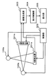
図1に示すように本実施形態に係るX線CT装置はX線照射部100a及びX線照射部100bという2つのX線照射部を有する。これら2つのX線照射部は同じ構成であるので以下では、それぞれのX線照射部を区別しない時は単に「X線照射部100」という。このX線照射部100が本発明における「X線照射手段」にあたる。このX線照射手段は一般的に「X線管球」とよばれることがある。さらに、本実施形態に係るX線CT装置はX線照射部100aと対になるX線検出器001a、及びX線照射部100bと対になるX線検出器001bという2つのX線検出器を有する。これら2つのX線検出器は同じ構成であるので以下では、それぞれのX線検出器を区別しない時には単に「X線検出器001」という。
As shown in FIG. 1, the X-ray CT apparatus according to the present embodiment includes two X-ray irradiation units, an
X線照射部100は、図2に示すように電子銃101、偏向用電極102、駆動部103、照射窓104、及びターゲット110、を有する。X線照射部100の内壁は銅で覆われている。これにより、X線照射部100の内壁に当たったX線は反射されずに吸収される。
As shown in FIG. 2, the X-ray irradiation unit 100 includes an
電子銃101は、インバータ、高圧トランス、及びフィラメントを有する。電子銃101は、フィラメントとターゲット110との間にインバータ及び高圧トランスで発生させた高電圧をかけ、フィラメントから飛び出した電子をターゲット110に衝突させることでX線を発生させる。電子銃101から発生し出射された電子ビームは図2の右側方向、すなわちターゲット110の第1表面111に向けて直進する。このとき、電子銃101から照射されるX線は偏向用電極102の間を通過する。
The
偏向用電極102は、2枚の金属の板で構成されており、その2枚の金属の間を電子銃101から出射された電子ビームが通過するように配置されている。そして、偏向用電極102は、電圧が掛けられると、金属の板の一方が陽極に、他方が陰極になる。本実施形態では図2における上側が陽極、下側が陰極になる。以下では、偏向用電極102に電圧が掛けられている状態をオン、偏向用電極102に電圧がかかっていない状態をオフという。
The
すなわち、偏向用電極102がオフのときには、電子銃101から出射された電子ビームは直進して第1表面111の方向に進み、偏向用電極102がオンのときには、電子銃101から出射された電子ビームは屈折して、第2表面112の方向へ進む。この様に偏向用電極102は、オン/オフにより電子銃101から出射された電子ビームを2つの方向に切り替えて送出する。この偏向用電極102が本発明における「偏向手段」にあたる。ここで、本実施形態では電極に電圧をかけて電場を発生することで電子ビームを偏向させているが、これは他の方法でもよく、例えばコイルを電子ビームの進行方向の横に配置し、該コイルに磁場をかけることで電子ビームを変更させるなどでもよい。
That is, when the
このオン/オフは、偏向用電極102が後述する制御部002(図1参照)からの制御信号を受けることで行われる。オンになった偏向用電極102は、電極間を通過する電子ビームを陽極側に屈折させ、該電子ビームの進行方向を変更する。この進路を変更された電子ビームは、第2表面112の方向へ進む。本実施形態では、電子銃101からの電子ビームの進行方向が変更されることで、後述するターゲット110に電子ビームが当たる位置が図2における上下の方向に3mm移動する。ここで、本実施形態では、進行方向の変更に係る時間を短くするとともに、後述するターゲット110から照射されるX線の方向を大きく異ならせるためにターゲット110上での移動距離が3mmとなるように電子ビームの屈折角度を調整している。ただし、この屈折角度は小さければ小さいほどオンとオフの応答性がよくなるが、角度が大きいほど反射後の電子ビームの方向をコントロールしやすい。そこで、この屈折角度は、オン/オフの応答速度とターゲット110から照射されるX線の方向のコントロールしやすさを考慮して決定することが好ましい。ただし、オン/オフの応答速度があまりに遅い場合、後述する複数のX線照射部100によるパルス状のX線照射を用いた交互の曝射が困難となるため、ターゲット110上の移動距離は数ミリであることが好ましい。
This on / off is performed when the
ターゲット110は「アノード」とも呼ばれ、銅やアルミなどで形成されている。ターゲット110は、図2に示すように円錐台状の上底面を凹ませた形状である。この円錐台状の形状が本発明における「円盤状」にあたる。さらに、ターゲット110における上底面の凹み部分は上底面の外周を頂上部として滑らかな斜面である第2表面112を有している。そして、ターゲット110の円錐台の外側面は上底面の外周を頂上部として滑らかな斜面である第1表面111を有している。この第1表面111が本発明における「第1の面」にあたる。また、第2表面112が本発明における「第2の面」にあたる。
The target 110 is also called an “anode” and is made of copper, aluminum, or the like. The target 110 has a shape in which the upper bottom surface of the truncated cone shape is recessed as shown in FIG. This frustoconical shape corresponds to the “disc shape” in the present invention. Further, the concave portion of the upper bottom surface of the target 110 has a
そして、ターゲット110は、電子銃101から電子ビームが出射される方向と、中心軸Aが平行になるように配置される。
The target 110 is arranged so that the direction in which the electron beam is emitted from the
また、ターゲット110は、電子銃101から出射され直進してきた電子ビームが第1表面111に当たるように配置される。本実施形態では第1表面111の図2における下側の部分に当たり、図2に示すように第1表面111において発生するX線が図2おける下方向に照射するように配置される。そして、第1表面111で発生したX線は照射窓104に向かって進み、照射窓104を通過して被検体上の照射野に向かって照射される。
Further, the target 110 is arranged so that the electron beam emitted from the
また、ターゲット110は、電子銃101から出射され偏向用電極102によって屈折されてきた電子ビームが第2表面112に当たるように配置されている。すなわち本実施形態では第1表面111で電子ビームが当たる位置から、第2表面112に電子ビームが当たる位置まで3mmの距離となるように構成されている。そして、図3に示すように第2表面112から照射されるX線は第1表面111から照射されるX線が進む方向と略反対の方向に進む。また、第2表面112から照射されたX線はX線照射部100の中の構造物(例えば、電子銃101やターゲット110など)に当たらずにX線照射部100の内壁に到達する方向に進むよう第2表面112の角度が調整されている。
Further, the target 110 is arranged so that the electron beam emitted from the
さらに、ターゲット110は、中心軸Aを中心に回転する。この回転は、一か所に電子ビームが照射され続けると高熱によりターゲット110が溶解してしまうため、回転させて電子ビームが照射されるターゲット110の位置を変更させていき、ターゲット110の溶解を防ぐためのものである。 Further, the target 110 rotates around the central axis A. This rotation causes the target 110 to melt due to high heat if it continues to be irradiated with an electron beam in one place. Therefore, the position of the target 110 irradiated with the electron beam is changed by rotation, so that the target 110 is melted. It is for prevention.
駆動部103は、ターゲット110を、中心軸Aを中心として回転させる。この駆動部103が本発明における「駆動手段」にあたる。 The drive unit 103 rotates the target 110 around the central axis A. The driving unit 103 corresponds to “driving means” in the present invention.
以上のように、第1表面111は進んできた電子ビームを受けて照射窓104の方向にX線を照射し、第2表面112は進んできた電子ビームを受けて照射窓104とは略反対方向で直接X線照射部100の内壁に当たる方向にX線を照射するように調整されている。これにより、偏向用電極102がオフのときは、電子銃101から出射された電子ビームが第1表面111にあたることでX線が発生し、該発生したX線が照射窓104を通過して照射野に照射される。また、偏向用電極102がオンのときは、電子銃101から照射された電子ビームが第2表面112にあたることでX線が発生し、該発生したX線がX線照射部100の内壁にあたり吸収される。したがって、偏向用電極102がオンのとき以外は、照射窓104から外へ向かうX線をほぼ遮断することができる。
As described above, the first surface 111 receives the advanced electron beam and emits X-rays in the direction of the irradiation window 104, and the
X線検出器001は、図4に示すように、シンチレータ401、フォトダイオード402、コンデンサ403、アース用スイッチ404、アンプ用スイッチ405、及びアンプ406を有している。
As shown in FIG. 4, the X-ray detector 001 includes a
シンチレータ401は、被検体を透過したX線を吸収して蛍光を発生する。フォトダイオード402は、シンチレータ401で発生した傾向を受信して電子に変換する。
The
X線検出器001は、制御部002からの制御信号を受けて、アース用スイッチ404及びアンプ用スイッチ405のオン/オフを行う。
The X-ray detector 001 receives a control signal from the
アース用スイッチ404及びアンプ用スイッチ405がオフのときには、コンデンサ403はシンチレータ401で生成された電子を貯蔵する。アース用スイッチ404がオンでアンプ用スイッチ405がオフのときには、コンデンサ403に蓄えられた電気をアースに流す。アース用スイッチ404がオフでアンプ用スイッチ405がオンのときには、コンデンサ403に蓄えられた電気はアンプ406で増幅され、画像生成部003に出力される。このアース用スイッチ404及びアンプ用スイッチ405のオン/オフは制御部002により行われ、そのオン/オフのタイミングの詳細は後にまとめて説明する。
When the
制御部002は、X線照射部100a及びX線照射部100bにおける、電子銃101からの電子ビームの出射及び偏向用電極102のオン/オフ,並びにX線検出器001a及びX線検出器001bのX線の検出を制御する。この制御部002が本発明における「制御手段」にあたる。以下、それぞれの制御について図5を参照して詳細に説明する。ここで、図5は制御部002におけるタイミングパルスと偏向用電極102のオン/オフ及び各X線照射部100からのX線照射のオン/オフとの関係を表すタイミングチャートの図である。このタイミングチャートは横軸を時間に縦軸を電圧又はX線の照射量のレベルに採ったものである。図5(A)は制御部002におけるタイミング信号のグラフ、図5(B)はX線照射部100aの偏向用電極102の電圧を表したグラフ、図5(C)はX線照射部100aの照射野へのX線照射量を表したグラフ、図5(D)はX線照射部100bの偏向用電極102の電圧を表したグラフ、図5(E)はX線照射部100bの照射野へのX線照射量を表したグラフである。
The
制御部002は、操作者から入力されたX線照射開始の命令を受信して電子銃101からの電子ビームの出射を開始させる。
The
さらに、制御部002は、図5に示すタイミングパルス500を生成している。制御部002は、タイミングパルス500が7n+1回の立ち上がりの時にX線照射部100aの偏向用電極102をオフにする制御信号をX線照射部100aに送信する。さらに、制御部002は、タイミングパルス500が7n+5回の立ち上がりの時にX線照射部100aの偏向用電極102をオンにする制御信号をX線照射部100aに送信する。また、制御部002は、タイミングパルス500が7n+1の立下りの時にX線照射部100bの偏向用電極102をオンにする制御信号をX線照射部100bに送信する。さらに、制御部002は、タイミングパルス500が7n+4回の立下りの時にX線照射部100bの偏向用電極102をオンにする制御信号をX線照射部100bに送信する。
Further, the
制御部002からオンの制御信号を受信した偏向用電極102は電圧を電極間にかける。これにより、電子銃101から出射された電子ビームは屈折し第2表面112にあたってX線を発生し、該発生したX線はX線照射部100の内壁、すなわち照射野以外に当たる。この状態を以下では、「X線オフ」の状態という。波形510における区間512、及び波形530における区間531が偏向用電極102がオンになった状態の区間である。そして、偏向用電極102がオンになることで、X線オフの状態になる開始点が波形520上の点523、及び波形540上の点541である。このとき電子銃101から出射された電子ビームの進路が徐々に変わっていくために、波形520及び波形540の立下りのグラフは傾斜している。
The
また、制御部002からオフの制御信号を受信した偏向用電極102は電極間にかけている電圧を停止させる。これにより、電子銃101から出射された電子ビームは直進し第1表面111にあたってX線を発生し、該発生したX線は照射窓104を通過して照射野に照射される。この状態を以下では、「X線オン」の状態という。波形510における区間511、及び波形530における区間532が偏向用電極102がオフになった状態の区間である。そして、偏向用電極102がオフになることで、X線オンの状態になる開始点が時刻t0で波形520上の点521、及び時刻t2で波形540上の点542である。このとき電子銃101から出射された電子ビームの進路は徐々に変わっていくために、波形520及び波形540の立ち上がりのグラフは傾斜している。そして、時刻t1での波形520上の点522、及び時刻t3での波形540上の点543で電子銃101から出射された電子ビームの進路の切り替えが終了し、X線は所定の照射野に向かって正確に照射される状態になる。
Further, the
以上のように制御することで、X線照射部100aの偏向用電極102がオフになり、X線照射部100aにおける電子銃101から出射された電子ビームの進行方向が第2表面112から第1表面111に向けて移動を時刻t0で開始し(点521)、該移動が終了してX線照射部100aから照射されたX線が正確に照射野に照射されるようになるタイミング(点522)と、X線照射部100bの偏向用電極102がオンになり、X線照射部100aから照射されたX線が正確に照射野に照射される位置からずれ始めるタイミング(点541)とが、時刻t1で一致する。同様に、X線照射部100bから照射されたX線が正確に照射野に照射されるようになるタイミング(点543)と、X線照射部100aの偏向用電極102がオンになり、X線照射部100aから照射されたX線が正確に照射野に照射される位置からずれ始めるタイミング(点523)とが、時刻t3で一致する。これにより、被検体に連続してX線を照射することが可能となる。また、両方のX線照射部100からの同時照射を防止して、各X線照射部100から高速のパルス状のX線を極めて短い周期で交互に照射することができる。
By controlling as described above, the
この、制御部002によるX線照射部100a及びX線照射部100bの偏向用電極102のオン/オフのタイミングは、それぞれの偏向用電極102がオフになっている時間が同一であり、さらに、一方の偏向用電極102がオンになるタイミングで他方の偏向用電極102による電子ビームの進行方向の切り替えが完了していれば、本実施形態以外でのタイミングでもよい。
The on / off timing of the
また、制御部002は、各X線照射部100からX線が正確に照射野に照射が行われるようになったタイミングで、X線検出器001へ、アース用スイッチ404及びアンプ用スイッチ405のオフの制御信号を送信する。これにより、コンデンサ403に電気のチャージが開始される。
Also, the
さらに、制御部002は、各X線照射部100からのX線が照射野からずれだすタイミングで、X線検出器001へ、アンプ用スイッチ405のオンの制御信号を送信する。これにより、コンデンサ403内に蓄えられた電気の読み出しが行われる。この読み出しは数十分の一秒単位といった瞬時に終了する。そのため、この読み出しを行っている間のノイズの影響は僅少であり無視できる。
Further, the
そして、制御部002は、コンデンサ403からの読み出しが終了したタイミングで、X線検出器001へ、アンプ用スイッチ405のオフの制御信号、及びアース用スイッチ404のオフの制御信号を送信する。これにより、この時点から次のX線照射部100からX線が正確に照射野に照射が行われるようになったタイミングまでの間にコンデンサ403に貯えられた電気はアースに流される、すなわちこの間に検出されたX線のデータは廃棄される。
The
以上の制御部002によるX線検出器001の制御の流れを動きに沿って説明する。時刻t1(点522)のタイミングで、X線検出器001aのコンデンサ403に電気のチャージが開始される。そして、時刻t3(点523)のタイミングでX線検出器001aのコンデンサ403へのチャージが終了する。すなわち波形520における区間524の間にX線検出器001aのコンデンサ403へのチャージが行われる。また、X線検出器001aのコンデンサ403に電気のチャージが開始と同時に時刻t1(点541)のタイミングで、X線検出器001bのコンデンサ403からの読み出しが開始され、読み出しが終了した後に送られてくるX線のデータの廃棄がなされる。そして、時刻t2(点542)のタイミングで、X線検出器001bのコンデンサ403に電気のチャージが開始される。そして、波形540における区間544の間にX線検出器001bのコンデンサ403へのチャージが行われる。
The flow of control of the X-ray detector 001 by the
以上のように、X線照射部100の動作とX線検出器001の動作を同期させて制御することで、X線照射部100aからのX線のデータ及びX線照射部100bからのX線のデータを、ノイズを除去して極めて短い周期で交互に取得することができる。したがって、2つの異なるX線照射部100から被検体の異なる照射野に向けて照射されたX線データを同時に取得し、そのX線データを基に画像生成することが可能となる。
As described above, the X-ray data from the
画像生成部003は,X線検出器001a及びX線検出器001bから入力されたデータに対して、感度補正やX線強度補正などを施す。そして、画像生成部003は、前述の処理を施したデータを再構成し画像データを生成する。さらに、画像生成部003は、入力装置(不図示)にて入力された操作者の指示に従って、画像データに対して様々な画像処理を施す。例えば、画像生成部003は、ボリュームレンダリング処理やMPR処理などを施して3次元画像データやMPR画像データ(任意断面の画像データ)を生成して表示制御部004へ出力する。
The
表示制御部004は、画像生成部003から入力された画像データに基づく画像を、液晶ディスプレイやCRTなどの表示部005に表示させる。
The
次に、図6を参照して本実施形態に係るX線CT装置におけるX線の照射及び検出の流れを説明する。ここで、図6は本実施形態に係るX線CT装置におけるX線の照射及び検出の流れを表すフローチャートの図である。 Next, the flow of X-ray irradiation and detection in the X-ray CT apparatus according to the present embodiment will be described with reference to FIG. Here, FIG. 6 is a flowchart showing the flow of X-ray irradiation and detection in the X-ray CT apparatus according to the present embodiment.
ステップS001:制御部002は、X線照射部100a及びX線照射部100bの双方の電子銃101からの電子ビームの出射を開始させる。
Step S001: The
ステップS002:制御部002は、自己が生成するタイミングパルスが7n+1(n=0,1,2・・・)の立ち上がりかを判断する。7n+1の立ち上がりであればステップS003に進む。7n+1の立ち上がりでなければステップS004に進む。
Step S002: The
ステップS003:X線照射部100aは、制御部002からの制御信号を受けて、偏向用電極102をオフにする。これにより、X線照射部100aはX線オンの状態になる。
Step S003: The
ステップS004:制御部002は、自己が生成するタイミングパルスが7n+1(n=0,1,2・・・)の立下りかを判断する。7n+1の立下りであればステップS005に進む。7n+1の立下りでなければステップS008に進む。
Step S004: The
ステップS005:X線照射部100bは、制御部002からの制御信号を受けて、偏向用電極102をオンにする。これにより、X線照射部100bはX線オフの状態になる。
Step S005: The
ステップS006:X線検出器001aは、制御部002からの制御信号を受けて、アース用スイッチ404を及びアンプ用スイッチ405をオフにする。これにより、X線検出器001aのコンデンサ403に電気がチャージされる。
Step S006: In response to the control signal from the
ステップS007:X線検出器001bは、アース用スイッチ404をオフにし、アンプ用スイッチ405をオフにする。これにより、X線検出器001bのコンデンサ403から読み出しが行われる。
Step S007: The X-ray detector 001b turns off the
ステップS008:制御部002は、自己が生成するタイミングパルスが7n+4(n=0,1,2・・・)の立下りかを判断する。7n+4の立下りであればステップS009に進む。7n+4の立下りでなければステップS010に進む。
Step S008: The
ステップS009:X線照射部100bは、制御部002からの制御信号を受けて、偏向用電極102をオフにする。これにより、X線照射部100bはX線オンの状態になる。
Step S009: The
ステップS010:制御部002は、自己が生成するタイミングパルスが7n+5(n=0,1,2・・・)の立ち上がりかを判断する。7n+5の立ち上がりであればステップS011に進む。7n+5の立ち上がりでなければステップS014に進む。
Step S010: The
ステップS011:X線照射部100aは、制御部002からの制御信号を受けて、偏向用電極102をオンにする。これにより、X線照射部100aはX線オフの状態になる。
Step S011: The
ステップS012:X線検出器001bは、制御部002からの制御信号を受けて、アース用スイッチ404を及びアンプ用スイッチ405をオフにする。これにより、X線検出器001bのコンデンサ403に電気がチャージされる。
Step S012: The X-ray detector 001b receives the control signal from the
ステップS013:X線検出器001aは、アース用スイッチ404をオフにし、アンプ用スイッチ405をオフにする。これにより、X線検出器001aのコンデンサ403から読み出しが行われる。
Step S013: The
ステップS014:制御部002は、X線検出器001aのコンデンサから読み出しが終了したかを確認する。終了している場合はステップS015に進む。終了していない場合はステップS016に進む。
Step S014: The
ステップS015:X線検出器001aは、制御部002からの制御信号を受けて、アース用スイッチ404をオンにし、アンプ用スイッチ405をオフにする。これにより、X線検出器001aで検出されるX線データは廃棄されることになる。
Step S015: In response to the control signal from the
ステップS016:制御部002は、X線検出器001bのコンデンサから読み出しが終了したかを確認する。終了している場合はステップS015に進む。終了していない場合はステップS016に進む。
Step S016: The
ステップS017:X線検出器001bは、制御部002からの制御信号を受けて、アース用スイッチ404をオンにし、アンプ用スイッチ405をオフにする。これにより、X線検出器001bで検出されるX線データは廃棄されることになる。
Step S017: In response to the control signal from the
ステップS018:制御部002は、X線の照射終了か否かを判断する。X線の照射終了の場合はステップS019に進む。X線の照射終了でない場合はステップS002に進む。
Step S018: The
ステップS018:制御部002は、X線照射部100a及びX線照射部100bの双方の電子銃101からの電子ビームの出射を停止させる。
Step S018: The
また、以上で説明した、2つのX線照射部及びその2つのX線照射部からのX線の照射を制御する制御部を有する装置が本発明におけるX線管装置にあたる。 Moreover, the apparatus which has the control part which controls two X-ray irradiation parts demonstrated above and the X-ray irradiation from the two X-ray irradiation parts corresponds to the X-ray tube apparatus in this invention.
以上で説明したように、本実施形態に係るX線CT装置においては、2つのX線照射部から異なる照射野に向けて交互に極めて短い周期でパルス状のX線の照射を行い、そのX線の照射と同期させて該X線をそれぞれ別個に他方のX線の散乱線の影響なく検出することができる。これにより、散乱線の影響の少ない異なる2つの照射野におけるX線データを同時に取得することができ、その取得したX線データを基にノイズの少ない異なる2つの画像をほぼ同時に生成することが可能なる。したがって、本実施形態に係るX線CT装置は、同時に異なる組織を対象にしたノイズの少ないX線CT画像を生成することができ、また、1枚のX線CT画像を生成する時間を短縮することもでき、その場合の画像もノイズを軽減させた画像として生成することができる。 As described above, in the X-ray CT apparatus according to the present embodiment, pulsed X-rays are alternately irradiated from two X-ray irradiation units toward different irradiation fields in a very short period, and the X-ray CT apparatus The X-rays can be detected separately without being affected by the scattered X-rays of the other X-rays in synchronization with the irradiation of the rays. As a result, X-ray data in two different irradiation fields that are less affected by scattered radiation can be acquired simultaneously, and two different images with less noise can be generated almost simultaneously based on the acquired X-ray data. Become. Therefore, the X-ray CT apparatus according to the present embodiment can generate an X-ray CT image with less noise for different tissues at the same time, and shortens the time for generating one X-ray CT image. The image in that case can also be generated as an image with reduced noise.
また、本実施形態では、2つのX線照射部を有するX線CT装置で説明を行ったが、このX線照射部は2つ以上あってもよい。その場合、X線が照射野に照射されるX線照射部を順次変更していき他のX線照射部からはX線が外部に照射されないようにし、さらに、そのX線が照射野に照射されるX線照射部に対応するX線検出器のみでX線の検出を行うように制御する構成となる。 In the present embodiment, the X-ray CT apparatus having two X-ray irradiation units has been described. However, two or more X-ray irradiation units may be provided. In that case, the X-ray irradiation unit irradiated with the X-ray is sequentially changed so that the other X-ray irradiation units do not emit the X-ray to the outside, and the X-ray is irradiated onto the irradiation field. The X-ray detection is performed only by the X-ray detector corresponding to the X-ray irradiation unit.
〔第2の実施形態〕
以下、この発明の第2の実施形態に係るX線CT装置について説明する。本実施形態に係るX線CT装置は第1の実施形態に係るX線CT装置において、X線照射部の中の第1反射面と照射窓との間に、第1反射面で反射したX線以外の散乱線が照射窓に入り込まないように遮蔽部材を設けたものである。そこで、以下では該遮蔽部材について主に説明する。本実施形態に係るX線CT装置の機能構成も第1の実施形態と同様に図1のブロック図で表わされる。
[Second Embodiment]
The X-ray CT apparatus according to the second embodiment of the present invention will be described below. The X-ray CT apparatus according to the present embodiment is the X-ray CT apparatus according to the first embodiment. The X-ray reflected by the first reflection surface between the first reflection surface and the irradiation window in the X-ray irradiation unit. A shielding member is provided so that scattered rays other than the rays do not enter the irradiation window. Therefore, the shielding member will be mainly described below. The functional configuration of the X-ray CT apparatus according to the present embodiment is also represented by the block diagram of FIG. 1 as in the first embodiment.
図7及び図8は、本実施形態に係るX線CT装置におけるX線照射部100の内部構造の概略図である。さらに、図7はX線が照射野に向かうときの状態の図であり、図8はX線が照射野とは反対方向に向かうときの状態の図である。 7 and 8 are schematic views of the internal structure of the X-ray irradiation unit 100 in the X-ray CT apparatus according to the present embodiment. Further, FIG. 7 is a diagram of a state when X-rays are directed toward the irradiation field, and FIG. 8 is a diagram of a state when X-rays are directed in a direction opposite to the irradiation field.
図7及び図8に示すように、本実施形態に係るX線CT装置は、X線照射部100の内部に、電子銃101から出射された電子ビームが第1表面111にあたって発生したX線が照射窓104に向かう進路を覆うように遮蔽部材105が配置されている。遮蔽部材105は、鉛などのX線が透過しない金属で構成されている。
As shown in FIGS. 7 and 8, the X-ray CT apparatus according to the present embodiment has X-rays generated from the
偏向用電極102がオフの場合には、電子銃101で出射された電子ビームが第1表面111にあたりX線が発生する。そして、図7に示すように、第1表面111から照射されたX線は、遮蔽部材105で覆われた進路を進み、照射窓104を通過して照射野に照射される。このように、第1表面111から照射されたX線は照射野にさえぎられることなく照射窓104に進める。
When the
偏向用電極102がオンの場合には、電子銃101で出射された電子ビームが第2表面112にあたってX線が発生する。図8に示すように、第2表面112から照射されたX線は、X線照射部100の内壁に向かう。X線照射部100の内壁は銅などのX線を吸収する材質で形成されているため、内壁に当たったX線のほとんどはX線照射部100の内壁で吸収される。しかし、X線照射部100の内壁に当たったX線のうち少量は散乱線としてX線照射部100の内部で反射を繰り返す。そして、この散乱線は図8に示す矢印800の様に照射窓104に向けて進む場合もある。そのような場合、本実施形態に係るX線CT装置では、散乱線は遮蔽部材105にさえぎられることで遮蔽部材105の内部には侵入しない。したがって、散乱線が照射窓104を通過してX線照射部100の外部に漏れることが軽減できる。
When the
以上で説明したように、本実施形態にかかるX線CT装置では、偏向用電極102がオフの場合には、電子銃101から出射された電子ビームが第1表面111にあたることでX線が発生し、該発生したX線は照射窓104を通過して照射野に照射される。そして、偏向用電極102がオフの場合には、電子銃101から出射された電子ビームが第2表面112にあたることでX線が発生し、該発生したX線はX線照射部100の内壁で一部が反射し散乱線となるが、この散乱線を遮蔽部材105で反射させることでX線照射部100の外部に漏らさないようにする構成である。これにより、X線オンになっているX線照射部100から照射されたX線のみを対になるX線検出器001に検出させることができ、ノイズをより軽減した画像を生成することが可能となる。
As described above, in the X-ray CT apparatus according to the present embodiment, when the
001a、001b X線検出器
002 制御部
003 画像生成部
004 表示制御部
005 表示部
100a、100b X線照射部
101 電子銃
102 偏向用電極
103 駆動部
104 照射窓
110 ターゲット(アノード)
111 第1表面
112 第2表面
001a,
111
Claims (7)
制御信号を受けて前記電子銃から出射された電子ビームを少なくとも2方向へ切り替えて送出させる偏向手段と、
一方向の前記電子ビームを受けたときは所定の照射野に向けてX線を照射する第1の面と、他の方向の前記電子ビームを受けたときは前記所定の照射野と異なる方向に向けてX線を照射する第2の面と、を有するターゲットと、
を備えることを特徴とするX線管装置。 An electron gun that emits an electron beam;
Deflecting means for receiving a control signal and switching and sending out an electron beam emitted from the electron gun in at least two directions;
When receiving the electron beam in one direction, the first surface irradiates X-rays toward a predetermined irradiation field, and when receiving the electron beam in the other direction, in a direction different from the predetermined irradiation field. A second surface that emits X-rays toward the target, and
An X-ray tube apparatus comprising:
前記第1X線照射手段と前記第2X線照射手段の2つの前記偏向手段において、一方の前記偏向手段に対して前記第1方向へ前記電子ビームを照射させている時に、他の前記偏向手段に対して前記第2方向に前記電子ビームを照射させる前記制御信号を送信する制御手段と、
を備えることを特徴とするX線管装置。 An electron gun that emits an electron beam; a deflection unit that receives a control signal to switch the electron beam emitted from the electron gun to at least two directions of a first direction and a second direction; and the electron beam in one direction The first surface for irradiating X-rays toward a predetermined irradiation field when received, and irradiating X-rays toward a direction different from the predetermined irradiation field when receiving the electron beam in another direction First X-ray irradiation means and second X-ray irradiation means each provided with a target having a second surface and arranged so as to be able to irradiate different irradiation fields for the same subject.
In the two deflection means of the first X-ray irradiation means and the second X-ray irradiation means, when one of the deflection means is irradiated with the electron beam in the first direction, the other deflection means Control means for transmitting the control signal for irradiating the electron beam in the second direction to the second direction;
An X-ray tube apparatus comprising:
前記n個のX線照射手段の前記偏向手段において、k(1≦k≦n)番目の前記X線照射手段の前記偏向手段に対して前記第1方向へ前記電子ビームを送出させている時に、他の前記X線照射手段の前記偏向手段に対して前記第2方向へ前記電子ビームを送出させる制御であって、前記k番目の前記X線照射手段を1からnまで順次変更していく制御となる前記制御信号を送信する制御手段と、
を備えることを特徴とするX線管装置。 An electron gun that emits an electron beam; a deflection unit that receives a control signal to switch the electron beam emitted from the electron gun to at least two directions of a first direction and a second direction; and the electron beam in one direction The first surface for irradiating X-rays toward a predetermined irradiation field when received, and irradiating X-rays toward a direction different from the predetermined irradiation field when receiving the electron beam in another direction N (2 ≦ n) X-ray irradiation means each provided with a target having a second surface and arranged so as to be able to irradiate different irradiation fields for the same subject,
In the deflection means of the n X-ray irradiation means, when the electron beam is sent in the first direction to the deflection means of the k (1 ≦ k ≦ n) th X-ray irradiation means. In this control, the deflecting means of the other X-ray irradiating means emits the electron beam in the second direction, and the kth X-ray irradiating means is sequentially changed from 1 to n. Control means for transmitting the control signal to be controlled;
An X-ray tube apparatus comprising:
前記ターゲットは、
前記X線発生手段の対向する位置に配置され、中心軸で回転する円盤状で、X線管球側に上底面を向け、前記上底面の外周を頂上部とする前記中心軸とは反対側へ向けた第1の面を有し、かつ前記上底面部分が前記頂上部から前記中心軸側に向けた滑らかな傾斜面である第2の面を有して凹んでいる、
ことを特徴とする請求項1に記載のX線管装置。 A driving means for rotating the target;
The target is
It is arranged at a position opposite to the X-ray generating means, is a disc shape rotating around a central axis, and is directed to the X-ray tube side with the upper bottom surface facing away from the central axis with the outer periphery of the upper bottom surface as the top. The upper bottom surface portion is recessed with a second surface that is a smooth inclined surface from the top toward the central axis.
The X-ray tube apparatus according to claim 1.
前記X線照射手段からのX線の照射を制御する制御手段と、
前記被検体を透過したX線を検出する前記X線照射手段と対になるX線検出器と、
前記検出したX線に基づくデータに対し再構成処理を行って画像データを生成する画像生成手段と、を備え、
前記X線照射手段は、
電子ビームを出射する電子銃と、制御信号を受けて前記電子銃から出射された前記電子ビームを少なくとも第1方向及び第2方向の2方向へ切り替えて送出させる偏向手段と、一方向の前記電子ビームを受けたときは所定の照射野に向けてX線を照射する第1の面と、他の方向の前記電子ビームを受けたときは前記所定の照射野と異なる方向に向けてX線を照射する第2の面と、を有するターゲットと、を備え、
前記制御手段は、
前記n個のX線照射手段の前記偏向手段において、k(1≦k≦n)番目の前記X線照射手段の前記偏向手段に対して前記第1方向へ前記電子ビームを送出させている時に、他の前記X線照射手段の前記偏向手段に対して前記第2方向へ前記電子ビームを送出させる制御であって、前記k番目の前記X線照射手段を1からnまで順次変更していく制御となる前記制御信号を送信する、
ことを特徴とするX線CT装置。 N X-ray irradiation means for irradiating X-rays toward different irradiation fields on the same subject;
Control means for controlling irradiation of X-rays from the X-ray irradiation means;
An X-ray detector paired with the X-ray irradiation means for detecting X-rays transmitted through the subject;
Image generation means for generating image data by performing reconstruction processing on the data based on the detected X-ray,
The X-ray irradiation means includes
An electron gun that emits an electron beam; a deflection unit that receives a control signal to switch the electron beam emitted from the electron gun to at least two directions of the first direction and the second direction; and the electron in one direction When receiving a beam, the first surface emits X-rays toward a predetermined irradiation field. When receiving the electron beam in another direction, X-rays are directed toward a different direction from the predetermined irradiation field. A target having a second surface to be irradiated, and
The control means includes
In the deflection means of the n X-ray irradiation means, when the electron beam is sent in the first direction to the deflection means of the kth (1 ≦ k ≦ n) th X-ray irradiation means. In this control, the deflecting means of the other X-ray irradiating means emits the electron beam in the second direction, and the kth X-ray irradiating means is sequentially changed from 1 to n. Transmitting the control signal to be controlled,
An X-ray CT apparatus characterized by that.
Priority Applications (1)
| Application Number | Priority Date | Filing Date | Title |
|---|---|---|---|
| JP2008186022A JP5438927B2 (en) | 2008-07-17 | 2008-07-17 | X-ray tube apparatus and X-ray CT apparatus |
Applications Claiming Priority (1)
| Application Number | Priority Date | Filing Date | Title |
|---|---|---|---|
| JP2008186022A JP5438927B2 (en) | 2008-07-17 | 2008-07-17 | X-ray tube apparatus and X-ray CT apparatus |
Publications (2)
| Publication Number | Publication Date |
|---|---|
| JP2010027340A true JP2010027340A (en) | 2010-02-04 |
| JP5438927B2 JP5438927B2 (en) | 2014-03-12 |
Family
ID=41732981
Family Applications (1)
| Application Number | Title | Priority Date | Filing Date |
|---|---|---|---|
| JP2008186022A Active JP5438927B2 (en) | 2008-07-17 | 2008-07-17 | X-ray tube apparatus and X-ray CT apparatus |
Country Status (1)
| Country | Link |
|---|---|
| JP (1) | JP5438927B2 (en) |
Cited By (1)
| Publication number | Priority date | Publication date | Assignee | Title |
|---|---|---|---|---|
| WO2013002124A1 (en) * | 2011-06-28 | 2013-01-03 | 株式会社 東芝 | X-ray tube and x-ray ct device |
Citations (4)
| Publication number | Priority date | Publication date | Assignee | Title |
|---|---|---|---|---|
| JPS49122764U (en) * | 1973-02-20 | 1974-10-21 | ||
| JPS50120375U (en) * | 1974-03-15 | 1975-10-01 | ||
| JPS63250122A (en) * | 1987-04-07 | 1988-10-18 | Nissin Electric Co Ltd | X-ray aligner |
| JP2005142160A (en) * | 2003-11-07 | 2005-06-02 | Ge Medical Systems Global Technology Co Llc | Multiple target anode assembly and its operation system |
-
2008
- 2008-07-17 JP JP2008186022A patent/JP5438927B2/en active Active
Patent Citations (4)
| Publication number | Priority date | Publication date | Assignee | Title |
|---|---|---|---|---|
| JPS49122764U (en) * | 1973-02-20 | 1974-10-21 | ||
| JPS50120375U (en) * | 1974-03-15 | 1975-10-01 | ||
| JPS63250122A (en) * | 1987-04-07 | 1988-10-18 | Nissin Electric Co Ltd | X-ray aligner |
| JP2005142160A (en) * | 2003-11-07 | 2005-06-02 | Ge Medical Systems Global Technology Co Llc | Multiple target anode assembly and its operation system |
Cited By (4)
| Publication number | Priority date | Publication date | Assignee | Title |
|---|---|---|---|---|
| WO2013002124A1 (en) * | 2011-06-28 | 2013-01-03 | 株式会社 東芝 | X-ray tube and x-ray ct device |
| JP2013031645A (en) * | 2011-06-28 | 2013-02-14 | Toshiba Corp | X-ray tube and x-ray ct device |
| CN103430630A (en) * | 2011-06-28 | 2013-12-04 | 株式会社东芝 | X-ray tube and x-ray CT device |
| US9418816B2 (en) | 2011-06-28 | 2016-08-16 | Toshiba Medical Systems Corporation | X-ray tube and X-ray CT device |
Also Published As
| Publication number | Publication date |
|---|---|
| JP5438927B2 (en) | 2014-03-12 |
Similar Documents
| Publication | Publication Date | Title |
|---|---|---|
| US7580500B2 (en) | Computer tomography system having a ring-shaped stationary X-ray source enclosing a measuring field | |
| JP2010240106A (en) | X-ray imaging device, control method therefor and computer program | |
| US9418816B2 (en) | X-ray tube and X-ray CT device | |
| JP2009533151A5 (en) | ||
| CN102640252A (en) | Rapidly switching dual energy X-ray source | |
| JP4495112B2 (en) | Radiotherapy apparatus control apparatus and radiation irradiation method | |
| KR20240011673A (en) | High-speed 3D radiography using a multipulse X-ray source by deflection of a tube electron beam using an electromagnetic field | |
| US9615438B2 (en) | CT devices and methods thereof | |
| JP2010533356A (en) | X-ray source for measuring radiation | |
| JP5438927B2 (en) | X-ray tube apparatus and X-ray CT apparatus | |
| US9620325B2 (en) | CT devices and methods thereof | |
| JP2007216018A (en) | X-ray computed tomography apparatus | |
| WO2010151171A1 (en) | Method for the radiographic defect inspection of circular weld seams on tubular members (embodiments) and a device for implementing same (embodiments) | |
| JP2002263090A (en) | Examination treatment apparatus | |
| EP0116622B1 (en) | Apparatus for producing a tomographic x-ray image | |
| JP5677596B2 (en) | X-ray equipment | |
| JP2020518356A (en) | Photon scanning device dose modulation | |
| JP5366419B2 (en) | X-ray equipment | |
| JP6377370B2 (en) | X-ray tube apparatus and X-ray CT apparatus | |
| TW201239939A (en) | X-ray generating apparatus and method of controlling x-ray generating apparatus | |
| JP2014099251A (en) | Multi-radiation generation tube and radiography system employing the same | |
| JP4126468B2 (en) | X-ray generator | |
| JP5823178B2 (en) | X-ray CT system | |
| JPS6329622A (en) | X-ray tomographic imaging apparatus | |
| JP2003290207A (en) | Multiple radiation source x-ray ct system |
Legal Events
| Date | Code | Title | Description |
|---|---|---|---|
| A621 | Written request for application examination |
Free format text: JAPANESE INTERMEDIATE CODE: A621 Effective date: 20110628 |
|
| A131 | Notification of reasons for refusal |
Free format text: JAPANESE INTERMEDIATE CODE: A131 Effective date: 20130205 |
|
| A521 | Request for written amendment filed |
Free format text: JAPANESE INTERMEDIATE CODE: A523 Effective date: 20130403 |
|
| TRDD | Decision of grant or rejection written | ||
| A01 | Written decision to grant a patent or to grant a registration (utility model) |
Free format text: JAPANESE INTERMEDIATE CODE: A01 Effective date: 20131119 |
|
| A61 | First payment of annual fees (during grant procedure) |
Free format text: JAPANESE INTERMEDIATE CODE: A61 Effective date: 20131216 |
|
| R150 | Certificate of patent or registration of utility model |
Ref document number: 5438927 Country of ref document: JP Free format text: JAPANESE INTERMEDIATE CODE: R150 Free format text: JAPANESE INTERMEDIATE CODE: R150 |
|
| S111 | Request for change of ownership or part of ownership |
Free format text: JAPANESE INTERMEDIATE CODE: R313117 |
|
| R350 | Written notification of registration of transfer |
Free format text: JAPANESE INTERMEDIATE CODE: R350 |
|
| S533 | Written request for registration of change of name |
Free format text: JAPANESE INTERMEDIATE CODE: R313533 |
|
| R350 | Written notification of registration of transfer |
Free format text: JAPANESE INTERMEDIATE CODE: R350 |