JP2010026166A - Optical fiber connection unit and optical fiber connecting tool - Google Patents
Optical fiber connection unit and optical fiber connecting tool Download PDFInfo
- Publication number
- JP2010026166A JP2010026166A JP2008186253A JP2008186253A JP2010026166A JP 2010026166 A JP2010026166 A JP 2010026166A JP 2008186253 A JP2008186253 A JP 2008186253A JP 2008186253 A JP2008186253 A JP 2008186253A JP 2010026166 A JP2010026166 A JP 2010026166A
- Authority
- JP
- Japan
- Prior art keywords
- optical fiber
- optical
- cable
- connector
- jig
- Prior art date
- Legal status (The legal status is an assumption and is not a legal conclusion. Google has not performed a legal analysis and makes no representation as to the accuracy of the status listed.)
- Granted
Links
Images


Abstract
Description
本発明は、光ファイバ同士を接続する光ファイバ接続器を有する光ファイバ接続ユニット及び光ファイバ接続用治具に関するものである。 The present invention relates to an optical fiber connection unit having an optical fiber connector for connecting optical fibers to each other and an optical fiber connection jig.
従来の光ファイバ接続器としては、例えば特許文献1に記載されているように、光ファイバを位置決めするV溝を有する下ハウジングと、光ファイバをV溝に押さえ付ける押圧部を有する上ハウジングと、下ハウジングのV溝と上ハウジングの押圧部とを重ね合わせた状態で下ハウジング及び上ハウジングを押圧する板ばねとを備えたものが知られている。
ところで、現地において上記従来技術のような光ファイバ接続器に光ケーブルを組み付ける場合には、スキルレス化のために、光ファイバ接続器に使い捨ての光ファイバ接続用治具が予め添付されていることがある。しかし、光ファイバ接続器に光ケーブルを組み付けた後には、光ファイバ接続用治具は全てゴミとなってしまう。このため、光ファイバ接続用治具を回収してリサイクルすることも行われているが、手間がかかるため改善が期待されており、光ファイバ接続用治具を再利用することが望まれている。 By the way, when assembling an optical cable to the optical fiber connector like the above-mentioned prior art locally, a disposable optical fiber connection jig is attached to the optical fiber connector in advance for skilllessness. is there. However, after assembling the optical cable to the optical fiber connector, all the optical fiber connection jigs become garbage. For this reason, the optical fiber connecting jig is also collected and recycled, but it is time-consuming and is expected to be improved, and it is desired to reuse the optical fiber connecting jig. .
本発明の目的は、光ファイバ接続器に光ケーブルを組み付けた後も光ファイバ接続用治具を使用し、敷設時に発生するゴミを減少させることができる光ファイバ接続ユニット及び光ファイバ接続用治具を提供することである。 An object of the present invention is to provide an optical fiber connection unit and an optical fiber connection jig that can reduce dust generated during installation by using an optical fiber connection jig even after an optical cable is assembled to an optical fiber connector. Is to provide.
本発明の光ファイバ接続ユニットは、異なる光ケーブルの光ファイバ同士を接続する光ファイバ接続器と、光ファイバ接続器に光ケーブルを組み付ける際に使用される光ファイバ接続用治具とを備え、光ファイバ接続器は、光ファイバを位置決めするベース部と、光ファイバをベース部に対して押さえる押さえ部とを有し、光ファイバ接続用治具は、治具本体と、治具本体の一面側に設けられ、光ファイバ接続器に光ケーブルを組み付ける際にベース部と押さえ部との境界部分に挿入される楔部と、治具本体の他面側に設けられ、光ファイバ接続器を位置決め収容する接続器収容部と、治具本体の他面側における接続器収容部の両側にそれぞれ設けられ、光ファイバ接続器に組み付けられた光ケーブルを固定する1対のケーブル固定部とを有することを特徴とするものである。 The optical fiber connection unit of the present invention includes an optical fiber connector for connecting optical fibers of different optical cables, and an optical fiber connection jig used when assembling the optical cable to the optical fiber connector, The fixture has a base portion for positioning the optical fiber and a pressing portion for pressing the optical fiber against the base portion, and the optical fiber connecting jig is provided on the jig main body and one surface side of the jig main body. , A wedge portion that is inserted into the boundary portion between the base portion and the holding portion when the optical cable is assembled to the optical fiber connector, and a connector housing that is provided on the other surface side of the jig body and that positions and accommodates the optical fiber connector And a pair of cable fixing portions that are provided on both sides of the connector housing portion on the other surface side of the jig body and fix the optical cable assembled to the optical fiber connector. And it is characterized in Rukoto.
このような本発明の光ファイバ接続ユニットにおいて、光ファイバ接続器に2本の光ケーブルを組み付ける場合には、まず光ファイバ接続器におけるベース部と押さえ部との境界部分に楔部が挿入されるように、光ファイバ接続用治具における治具本体の一面側に光ファイバ接続器を配置する。すると、楔部によってベース部と押さえ部との境界部分が開くようになる。その状態で、各光ケーブルの先端部の外被を除去して露出された光ファイバを光ファイバ接続器の両端側から光ファイバ接続器内に導入し、光ファイバ同士を突き合わせる。そして、光ファイバ接続器を光ファイバ接続用治具から外し、ベース部と押さえ部との境界部分から楔部を引き抜くことで、ベース部と押さえ部とが閉じた状態となり、各光ファイバが接続された状態で光ファイバ接続器に固定されることとなる。その後、光ファイバ接続用治具における治具本体の他面側の接続器収容部に光ケーブル付きの光ファイバ接続器を収容する。そして、光ファイバ接続器に組み付けられた各光ケーブルをそれぞれケーブル固定部に固定し、その状態で光ケーブル付きの光ファイバ接続器を光ファイバ接続用治具と共に設置する。 In such an optical fiber connection unit of the present invention, when two optical cables are assembled to the optical fiber connector, first, a wedge portion is inserted into a boundary portion between the base portion and the pressing portion in the optical fiber connector. In addition, an optical fiber connector is arranged on one side of the jig body in the optical fiber connection jig. Then, the boundary portion between the base portion and the pressing portion is opened by the wedge portion. In this state, the optical fiber exposed by removing the outer sheath at the tip of each optical cable is introduced into the optical fiber connector from both ends of the optical fiber connector, and the optical fibers are brought into contact with each other. Then, remove the optical fiber connector from the optical fiber connection jig and pull out the wedge part from the boundary part between the base part and the holding part, so that the base part and the holding part are closed, and each optical fiber is connected. In this state, it is fixed to the optical fiber connector. Thereafter, the optical fiber connector with the optical cable is accommodated in the connector accommodating portion on the other surface side of the jig main body in the optical fiber connection jig. And each optical cable assembled | attached to the optical fiber connector is each fixed to a cable fixing part, and the optical fiber connector with an optical cable is installed with the jig for optical fiber connection in the state.
これにより、敷設後に光ケーブルに外力がかかった場合でも、その力をケーブル固定部が支えることになり、直接光ファイバ接続器に力にかかることが無いため、光ファイバの特性の悪化が抑えられる。このように光ファイバ接続器への光ケーブルの組み付けが完了した後には、光ファイバ接続用治具は、そのまま捨てられずに、光ファイバ接続器や光ファイバを保護する部材として有効利用されることとなる。その結果、敷設時に発生するゴミを減少させることができる。 As a result, even when an external force is applied to the optical cable after laying, the force is supported by the cable fixing portion and is not directly applied to the optical fiber connector, so that deterioration of the optical fiber characteristics can be suppressed. After the assembly of the optical cable to the optical fiber connector is completed in this way, the optical fiber connecting jig is not discarded as it is, but effectively used as a member for protecting the optical fiber connector and the optical fiber. Become. As a result, dust generated at the time of laying can be reduced.
好ましくは、ケーブル固定部は、光ファイバ接続器に組み付けられた光ケーブルを挟持して固定するように構成され、ケーブル固定部には、光ケーブルがケーブル固定部に挟持された状態において光ケーブル及びケーブル固定部を一緒に締め付けるための締付部材を沿わせる凹状部が形成されている。 Preferably, the cable fixing unit is configured to clamp and fix the optical cable assembled to the optical fiber connector, and the cable fixing unit includes the optical cable and the cable fixing unit in a state where the optical cable is clamped by the cable fixing unit. A concave portion is formed along a fastening member for fastening the two together.
光ファイバ接続器に組み付けられた光ケーブルをケーブル固定部により挟持する構成とすることで、光ケーブルを簡単に固定することができる。このとき、締付部材をケーブル固定部の凹状部に沿わせて、締付部材により光ケーブル及びケーブル固定部を一緒に締め付けることにより、光ケーブルがケーブル固定部から外れることが確実に防止される。また、光ケーブル付きの光ファイバ接続器が取り付けられた光ファイバ接続用治具を幹線ケーブルや柱等の不動物体に設置する場合には、ケーブル固定部に固定された光ケーブルと光ファイバ接続用治具と不動物体とを一緒に締付部材で締め付けて固定することにより、外力によって光ファイバ接続器が動くことが抑えられるため、光ファイバの特性に影響を与えることが防止される。 By adopting a configuration in which the optical cable assembled to the optical fiber connector is sandwiched between the cable fixing portions, the optical cable can be easily fixed. At this time, the optical cable and the cable fixing portion are fastened together by the fastening member along the concave portion of the cable fixing portion, so that the optical cable is reliably prevented from coming off from the cable fixing portion. Also, when installing an optical fiber connection jig with an optical fiber connector with an optical cable attached to an inanimate body such as a trunk cable or a pillar, the optical cable fixed to the cable fixing portion and the optical fiber connection jig By tightening and fixing the animal body and the inanimate body together with a fastening member, it is possible to prevent the optical fiber connector from moving due to an external force, thereby preventing the influence on the characteristics of the optical fiber.
また、好ましくは、接続器収容部は、光ファイバ接続器が接続器収容部に位置決め収容されたときに、1対のケーブル固定部の配列方向に対して光ファイバ接続器との間にクリアランスを持つような長さ寸法を有している。 Preferably, the connector housing portion has a clearance between the optical fiber connector and the optical fiber connector when the optical fiber connector is positioned and housed in the connector housing portion. It has such a length dimension.
この場合には、光ファイバ接続用治具の接続器収容部に光ケーブル付きの光ファイバ接続器が収容された状態において、ケーブル固定部に固定された光ケーブルに極めて強い力がかかり、ケーブル固定部だけでは耐えきれないために光ファイバ接続器が引っ張られようとしても、光ファイバ接続器が各ケーブル固定部の配列方向に僅かに動くようになる。これにより、光ファイバの特性の悪化を十分に軽減することができる。 In this case, in the state where the optical fiber connector with the optical cable is accommodated in the connector accommodating part of the optical fiber connecting jig, an extremely strong force is applied to the optical cable fixed to the cable fixing part, and only the cable fixing part is applied. In this case, even if the optical fiber connector is pulled, the optical fiber connector slightly moves in the arrangement direction of the cable fixing portions. Thereby, the deterioration of the characteristic of an optical fiber can fully be reduced.
また、本発明は、光ファイバ接続器に光ケーブルを組み付ける際に使用される光ファイバ接続用治具であって、治具本体と、治具本体の一面側に設けられ、光ファイバ接続器に光ケーブルを組み付ける際にベース部と押さえ部との境界部分に挿入される楔部と、治具本体の他面側に設けられ、光ファイバ接続器を位置決め収容する接続器収容部と、治具本体の他面側における接続器収容部の両側にそれぞれ設けられ、光ファイバ接続器に組み付けられた光ケーブルを固定する1対のケーブル固定部とを有することを特徴とするものである。 Further, the present invention is an optical fiber connecting jig used when assembling an optical cable to an optical fiber connector, and is provided on the jig main body and one surface side of the jig main body. A wedge portion that is inserted into a boundary portion between the base portion and the pressing portion, a connector housing portion that is provided on the other surface side of the jig body, and positions and accommodates the optical fiber connector, and a jig body It is provided on both sides of the connector housing portion on the other surface side, and has a pair of cable fixing portions for fixing the optical cable assembled to the optical fiber connector.
このような本発明の光ファイバ接続用治具を使用して、光ファイバ接続器に光ケーブルを組み付けた後には、光ファイバ接続用治具は、上述したように光ファイバ接続器や光ファイバを保護する部材として有効利用されることとなる。これにより、敷設時に発生するゴミを減少させることができる。 After assembling the optical cable to the optical fiber connector using the optical fiber connector jig of the present invention, the optical fiber connector jig protects the optical fiber connector and the optical fiber as described above. It will be used effectively as a member to do. Thereby, the dust generated at the time of laying can be reduced.
本発明によれば、光ファイバ接続器に光ケーブルを組み付けた後も光ファイバ接続用治具を使用し、敷設時に発生するゴミを減少させることができる。これにより、例えば光ファイバ接続用治具を回収してリサイクルする等といった手間を省くことが可能となる。 According to the present invention, it is possible to reduce dust generated at the time of laying by using the optical fiber connecting jig even after the optical cable is assembled to the optical fiber connector. Thereby, for example, it is possible to save the trouble of collecting and recycling the optical fiber connecting jig.
以下、本発明に係る光ファイバ接続ユニット及び光ファイバ接続用治具の好適な実施形態について図面を参照して詳細に説明する。 DESCRIPTION OF EMBODIMENTS Hereinafter, preferred embodiments of an optical fiber connection unit and an optical fiber connection jig according to the present invention will be described in detail with reference to the drawings.
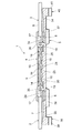
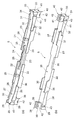
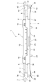
図1は、本発明に係る光ファイバ接続ユニットの一実施形態を示す斜視図である。また、図2は、図1に示した光ファイバ接続ユニットの光ファイバ接続器に光ケーブルが組み付けられた状態を示す斜視図であり、図3は、図2に示した状態の垂直方向断面図である。 FIG. 1 is a perspective view showing an embodiment of an optical fiber connection unit according to the present invention. 2 is a perspective view showing a state in which an optical cable is assembled to the optical fiber connector of the optical fiber connection unit shown in FIG. 1, and FIG. 3 is a vertical sectional view of the state shown in FIG. is there.
各図において、本実施形態の光ファイバ接続ユニット1は、光ケーブル2の光ファイバ2aと光ケーブル3の光ファイバ3aとを接続する光ファイバ接続器4と、この光ファイバ接続器4に光ケーブル2,3を組み付ける際に使用される光ファイバ接続用治具5とからなっている。光ケーブル2,3は、例えば外形寸法の異なるドロップケーブルで構成されている。光ケーブル2,3には、ケーブルホルダ6が装着されている。
In each figure, an optical
光ファイバ接続器4は、光ケーブル2の外被7から露出された光ファイバ2aと光ケーブル3の外被8から露出された光ファイバ3aとを機械的に接続する断面略矩形状のメカニカルスプライス9と、このメカニカルスプライス9を収容する断面略矩形状のハウジング10とを備えている。
The
メカニカルスプライス9は、図4に示すように、光ファイバ2a,3aを位置決めするV溝11を有するベースプレート12と、V溝11に配置された光ファイバ2a,3aをベースプレート12に対して押さえる押さえプレート13と、ベースプレート12及び押さえプレート13を挟み込む複数のU字状のクランプバネ14とを有している。
As shown in FIG. 4, the
メカニカルスプライス9におけるベースプレート12と押さえプレート13との境界部分には、光ファイバ接続用治具5の楔部25(後述)が挿入される複数(ここでは4つ)の楔挿入凹部15が設けられている。楔挿入凹部15の開口縁部には、楔部25を入れやすくするための面取りが形成されているのが好ましい。ベースプレート12及び押さえプレート13は、楔挿入凹部15の反対側からクランプバネ14に挟み込まれている。
A plurality (four in this case) of wedge insertion recesses 15 into which wedge portions 25 (described later) of the optical
メカニカルスプライス9は、楔挿入凹部15がハウジング10の下側に位置するようにハウジング10内に収容されている。なお、メカニカルスプライス9は、係止手段(図示せず)によりハウジング10に係止されている。ハウジング10の下壁には、光ファイバ接続用治具5の楔部25(後述)を貫通させて楔挿入凹部15に挿入させるための貫通長穴16(図8参照)が形成されている。
The
ハウジング10の両端部には、ハウジング10の上面に開放し、光ケーブル2,3に装着されたケーブルホルダ6を収容するホルダ収容部17がそれぞれ設けられている。ハウジング10の両端部近傍の両側壁には、ケーブルホルダ6の係止爪(図示せず)と係合する係止受け部18がそれぞれ設けられている。これにより、ホルダ収容部17に収容されたケーブルホルダ6がハウジング10の両側壁に係止されることとなる。
At both ends of the
また、ハウジング10の下壁における貫通長穴16の長手方向両側には、光ファイバ接続用治具5のファイバガイド突起26(後述)を貫通させる貫通穴19がそれぞれ形成されている。
In addition, on both sides in the longitudinal direction of the through
光ファイバ接続用治具5は、図5に示すように、長板状の治具本体20を有している。治具本体20の表面側には、光ケーブル2,3を光ファイバ接続器4に組み付ける時に光ファイバ接続器4を位置決め収容する接続器収容部21が設けられている(図1及び図2参照)。接続器収容部21は、治具本体20の長手方向一端側に位置する1対のL字状の壁部22と、治具本体20の長手方向他端側に位置する1対のL字状の壁部23とで形成されている。各壁部22,23は、治具本体20の両側縁部に設けられ、光ファイバ接続器4を治具本体20の長手方向及び幅方向に対して拘束する。
As shown in FIG. 5, the optical
接続器収容部21は、治具本体20の長手方向に延びる楔突起24を有し、この楔突起24には、上記のメカニカルスプライス9の各楔挿入凹部15に挿入される4つの楔部25が設けられている。
The
また、接続器収容部21において楔突起24の長手方向両側には、光ケーブル2,3を光ファイバ接続器4に組み付ける時に光ケーブル2,3の光ファイバ2a,3aを光ファイバ接続器4に対して案内するためのファイバガイド突起26がそれぞれ設けられている。
Further, the
治具本体20の表面側の一端側部分には、光ケーブル2を光ファイバ接続器4に組み付ける時に光ケーブル2を保持したケーブルホルダ6を光ファイバ接続器4に向けて案内するためのホルダガイド部27が設けられている(図2参照)。ホルダガイド部27は、接続器収容部21の一部を形成する各壁部22と一体化され治具本体20の一端側に延びる1対の壁部28と、治具本体20の一端部の各隅部に位置する1対のL字状の壁部29とで形成されている。ホルダガイド部27は、治具本体20の一端から接続器収容部21に向かって下がるような傾斜面30を有している。
A
治具本体20の表面側の他端側部分には、光ケーブル3を光ファイバ接続器4に組み付ける時に光ケーブル3を保持したケーブルホルダ6を光ファイバ接続器4に向けて案内するためのホルダガイド部31が設けられている(図2参照)。ホルダガイド部31は、接続器収容部21の一部を形成する各壁部23と一体化され治具本体20の他端側に延びる1対の壁部32と、治具本体20の他端部の各隅部に位置する1対のL字状の壁部33とで形成されている。ホルダガイド部31は、治具本体20の他端から接続器収容部21に向かって下がるような傾斜面34を有している。
A holder guide portion for guiding the
なお、ホルダガイド部27,31の幅寸法は、接続器収容部21の幅寸法よりも狭くなっている。
In addition, the width dimension of the
治具本体20の裏面側には、図5〜図7に示すように、光ケーブル2,3が組み付けられた光ファイバ接続器4を位置決め収容する接続器収容部35が設けられている。接続器収容部35は、治具本体20の長手方向一端側に位置する1対のL字状の壁部36と、治具本体20の長手方向他端側に位置する1対のL字状の壁部37とで形成されている。各側壁部36,37には、光ファイバ接続器4を光ファイバ接続用治具5に固定するためのリブ(図示せず)が設けられている。各壁部36,37は、治具本体20の両側縁部に設けられ、光ファイバ接続器4を治具本体20の幅方向に対して拘束する。
As shown in FIGS. 5 to 7, a
接続器収容部35の長手方向の長さ寸法は、光ファイバ接続器4の長手方向の長さ寸法よりも大きくなっている。このため、光ファイバ接続器4を接続器収容部35に収容した状態では、図6に示すように、光ファイバ接続器4と接続器収容部35との間には治具本体20の長手方向にクリアランスを持つこととなる。この時のクリアランスとしては、5mm〜10mm程度であることが望ましい。これにより、光ファイバ接続器4は、接続器収容部35に緩やかに固定されることとなり、治具本体20の長手方向に微動可能となる。
The length dimension of the
治具本体20の裏面側の一端部には、光ファイバ接続器4に組み付けられた光ケーブル2を固定するケーブル固定部38が設けられている。ケーブル固定部38は、光ケーブル2を挟持する1対の挟持壁39を有し、各挟持壁39の内壁面には、光ケーブル2の外被7に食い込んで光ケーブル2を固定するための複数の刃部(図示せず)が形成されている。なお、各挟持壁39間の幅寸法は、光ケーブル2の外形寸法に合ったものとなっている。
A
治具本体20の裏面側の他端部には、光ファイバ接続器4に組み付けられた光ケーブル3を固定するケーブル固定部40が設けられている。ケーブル固定部40は、光ケーブル3を挟持する1対の挟持壁41を有し、各挟持壁41の内壁面にも、ケーブル固定部38と同様に複数の刃部(図示せず)が形成されている。なお、各挟持壁41間の幅寸法は、光ケーブル3の外形寸法に合ったものとなっている。
A
ケーブル固定部38の各ガイト壁部39の上部には、光ケーブル2が各ガイト壁部39に挟持された状態において光ケーブル2及び光ファイバ接続用治具5を一緒に締め付けるための結束バンド45(図9参照)を沿わせる締付用切欠部42が形成されている。ケーブル固定部40の各ガイト壁部41の上部にも、同様の締付用切欠部42が形成されている。また、治具本体20の両側面における各締付用切欠部42に対応する部位には、上記と同様に結束バンド45を沿わせる締付用溝部43がそれぞれ形成されている。
Bundling
次に、以上のように構成した光ファイバ接続ユニット1を用いて光ケーブル2,3同士を接続する方法について説明する。
Next, a method for connecting the
ここでは、マンションやビル等において、複数の光ケーブルの集合体である縦系の幹線ケーブルと各戸へと繋がっている横系ケーブルとを接続する場合を想定する。この場合、幹線ケーブルをまとめてマンション等の最上階まで予め敷設しておき、必要に応じて各階で幹線ケーブルを切断して光ケーブル2を取り出し、この光ケーブル2と各戸に繋がる光ケーブル3とを光ファイバ接続器4により接続する。これにより、幹線ケーブルを毎回敷設する手間を省くことができ、各戸へのケーブル引き込み工事を短時間で且つ低コストで行うことが可能となる。
Here, in a condominium, a building, or the like, a case is assumed where a vertical trunk cable that is an assembly of a plurality of optical cables and a horizontal cable connected to each door are connected. In this case, the trunk cables are collectively laid up to the top floor of an apartment, etc., the trunk cables are cut at each floor as necessary, the
まず、光ケーブル2をケーブルホルダ6に装着すると共に、光ケーブル2の先端部分の外被7を除去して光ファイバ2aを露出させ、光ファイバ2aの露出部分が所定長となるように光ファイバ2aを切断する等といった端末処理を行う。また、光ケーブル3をケーブルホルダ6に装着すると共に、光ケーブル3の先端部分の外被8を除去して光ファイバ3aを露出させ、上記と同様に光ファイバ3aの端末処理を行う。
First, the
また、図1に示すように、光ファイバ接続用治具5の表面側の接続器収容部21に光ファイバ接続器4を収容する。このとき、光ファイバ接続用治具5の楔突起24に設けられた各楔部25が光ファイバ接続器4におけるハウジング10の貫通長穴16を貫通してメカニカルスプライス9の各楔挿入凹部15に入り込むため、図4(a)に示すように、メカニカルスプライス9のベースプレート12及び押さえプレート13がクランプバネ14の付勢力に抗して開いた状態となる。
Further, as shown in FIG. 1, the
次いで、光ケーブル2が装着されたケーブルホルダ6を、光ファイバ接続用治具5の表面側のホルダガイド部27に置く。そして、ホルダガイド部27の傾斜面30に沿って当該ケーブルホルダ6を光ファイバ接続器4側に摺動させることで、図2に示すように、光ケーブル2付きのケーブルホルダ6が光ファイバ接続器4の一方のホルダ収容部17に収容されると共に、光ケーブル2の光ファイバ2aが光ファイバ接続用治具5の一方のファイバガイド突起26にガイドされてメカニカルスプライス9内に導入される。
Next, the
また、光ケーブル3が装着されたケーブルホルダ6を、光ファイバ接続用治具5の表面側のホルダガイド部31に置く。そして、ホルダガイド部31の傾斜面34に沿って当該ケーブルホルダ6を光ファイバ接続器4側に摺動させることで、図2に示すように、光ケーブル3付きのケーブルホルダ6が光ファイバ接続器4の他方のホルダ収容部17に収容されると共に、光ケーブル3の光ファイバ3aが光ファイバ接続用治具5の他方のファイバガイド突起26にガイドされてメカニカルスプライス9内に導入される。
The
これにより、図3に示すように、光ケーブル2,3が光ファイバ接続器4に組み付けられ、光ファイバ2a,3a同士が突き合わされることとなる。
Thereby, as shown in FIG. 3, the
次いで、光ケーブル2,3が組み付けられた光ファイバ接続器4を光ファイバ接続用治具5から外す。これにより、図4(b)に示すように、光ファイバ接続用治具5の各楔部25がメカニカルスプライス9の各楔挿入凹部15から抜去されるため、メカニカルスプライス9のベースプレート12及び押さえプレート13がクランプバネ14の付勢力により閉じられ、光ファイバ2a,3a同士が接続された状態でメカニカルスプライス9に固定されることとなる。
Next, the
その後、光ファイバ接続用治具5を上下逆さにした状態で、図6及び図7に示すように、光ケーブル2,3が組み付けられた光ファイバ接続器4を、光ファイバ接続用治具5の裏面側の接続器収容部35に収容する。このとき、光ファイバ接続器4と接続器収容部35との間には光ファイバ接続用治具5の長手方向に対してある程度のクリアランスを持っているため、光ファイバ接続器4を接続器収容部35に容易に嵌め込むことができる。
Thereafter, with the optical
そして、光ケーブル2をケーブル固定部38の上方から各挟持壁39間に押し込むことで、光ケーブル2をケーブル固定部38に固定させる。また、光ケーブル3をケーブル固定部40の上方から各挟持壁41間に押し込むことで、光ケーブル3をケーブル固定部40に固定させる。
Then, the
その後、図9に示すように、光ファイバ接続器4が光ファイバ接続用治具5に対して上側となるように、光ケーブル2,3が組み付けられた光ファイバ接続ユニット1を幹線ケーブル44上に配置する。そして、その状態で、2本の結束バンド45により光ファイバ接続用治具5を幹線ケーブル44に縛り付けて固定する。具体的には、ケーブル固定部38,40の上を結束バンド45が通るように、光ファイバ接続用治具5の両端近傍に設けられた各締付用切欠部42及び各締付用溝部43に結束バンド45をそれぞれ沿わせて、光ファイバ接続用治具5及び幹線ケーブル44を結束バンド45で一緒に締め付けて固定する。これにより、光ケーブル2,3がケーブル固定部38,40から外れてしまうことが防止される。以上により、光ファイバ接続ユニット1の敷設作業が完了する。
Thereafter, as shown in FIG. 9, the optical
以上のように本実施形態においては、光ファイバ接続用治具5の裏面側に接続器収容部35及びケーブル固定部38,40を設けることにより、光ファイバ接続用治具5を用いて光ファイバ接続器4に光ケーブル2,3を組み付けた後に、光ケーブル2,3が組み付けられた光ファイバ接続器4を光ファイバ接続用治具5の裏面側に取り付けた状態で現地に設置することができる。つまり、光ファイバ接続用治具5を使い捨てるのではなく再利用できるような構造としたので、敷設作業時に発生するゴミを減らすことができる。
As described above, in the present embodiment, the optical
このとき、光ファイバ接続器4に組み付けられた光ケーブル2,3を光ファイバ接続用治具5のケーブル固定部38,40に固定するので、光ケーブル2,3に何らかの外力が加わっても、その外力はケーブル固定部38,40で支えられることになる。このため、光ファイバ接続器4に直接力がかかりにくくなり、光ファイバ2a,3aの特性悪化の抑制につながる。このように光ファイバ接続用治具5がメカニカルスプライス9を保護する機能を果たすこととなるため、メカニカルスプライス9を保護する専用のケース等を別途購入する必要が無く、コスト削減を図ることができる。
At this time, since the
また、光ケーブル2,3に十分強い力が加わった場合には、その力をケーブル固定部38,40だけでは支えきれず、光ファイバ接続器4に影響を与えることが考えられる。このとき、光ファイバ接続器4と光ファイバ接続用治具5とが完全に固定されていると、光ケーブル2,3が引っ張られたときに光ファイバ接続器4に対する引っ張り力が発生し、光ファイバ2a,3aの特性悪化を引き起こすことがある。しかし、光ファイバ接続用治具5の接続器収容部35に収容された光ファイバ接続器4は光ファイバ接続用治具5の長手方向に対して微動可能になっており、光ケーブル2,3が引っ張られたときは光ファイバ接続器4が動くため、光ファイバ2a,3aの特性の悪化を防止することができる。
In addition, when a sufficiently strong force is applied to the
さらに、光ファイバ接続用治具5の両端側に締付用切欠部42及び締付用溝部43を形成し、光ファイバ接続用治具5のケーブル固定部38,40に固定された光ケーブル2,3、光ファイバ接続用治具5及び幹線ケーブル44をまとめて結束バンド45で締め付けて固定するようにしたので、光ファイバ接続用治具5が外力によって動くことが防止される。これにより、光ファイバ2a,3aの特性に与える影響を十分軽減することができる。
Further, a
なお、本発明は、上記実施形態に限定されるものではない。例えば上記実施形態では、外形寸法の異なる光ケーブル2,3に対応するために、ケーブル固定部38の各挟持壁39間の幅寸法を光ケーブル2の外形寸法に合わせ、ケーブル固定部40の各挟持壁41間の幅寸法を光ケーブル3の外形寸法に合わせるようにしたが、特にそのような構造には限られない。例えば、使用する光ケーブル2,3の外形寸法に対応させた外形寸法の等しい複数種類のケーブル固定ホルダを準備し、これらのケーブル固定ホルダを光ファイバ接続用治具に着脱自在に取り付ける構造としても良い。
The present invention is not limited to the above embodiment. For example, in the above embodiment, in order to correspond to the
また、上記実施形態では、外形寸法の異なる光ケーブル2,3を使用したが、仕様等によっては外形寸法の等しい光ケーブル2,3を使用しても勿論構わない。この場合には、ケーブル固定部38の各挟持壁39間の幅寸法とケーブル固定部40の各挟持壁41間の幅寸法とを等しくすれば良い。
Moreover, in the said embodiment, although the
さらに、上記実施形態では、2本の結束バンド45を用いて、光ケーブル2,3が組み付けられた光ファイバ接続ユニット1を幹線ケーブル44に締め付けて固定するようにしたが、結束バンド45の代わりに、ワイヤ、ロープ及び紐等を使用しても良い。
Furthermore, in the above-described embodiment, the optical
また、光ケーブル2,3を光ファイバ接続用治具5に強く固定するためには、光ファイバ接続用治具5と光ケーブル2,3とを一緒に結束バンド45等の締付部材で締め付ける構造以外にも、例えばケーブル固定部38,40の上に光ケーブル2,3を上方から押さえる蓋部を設けても良い。この場合、蓋部は、光ファイバ接続用治具とは別の部品で構成しても良いし、ケーブル固定部と一体成形しても良い。
In addition, in order to strongly fix the
また、上記実施形態は、単心の光ファイバ2a,3a同士を接続するものであるが、本発明は、複数心の光ファイバ同士の接続にも適用可能である。
Moreover, although the said embodiment connects single
なお、上記実施形態においては、治具本体20の「表面」、「裏面」と表記したが、絶対的な表裏を示したものではなく、あくまで相対的関係としての「一方の面(一面)」、「他方の面(他面)」を表したものである。
In the above-described embodiment, the “front surface” and “back surface” of the
1…光ファイバ接続ユニット、2…光ケーブル、2a…光ファイバ、3…光ケーブル、3a…光ファイバ、4…光ファイバ接続器、5…光ファイバ接続用治具、9…メカニカルスプライス、12…ベースプレート(ベース部)、13…押さえプレート(押さえ部)、15…楔挿入凹部、20…治具本体、25…楔部、35…接続器収容部、38…ケーブル固定部、40…ケーブル固定部、42…締付用切欠部(凹状部)、45…結束バンド(締付部材)。
DESCRIPTION OF
Claims (4)
前記光ファイバ接続器に前記光ケーブルを組み付ける際に使用される光ファイバ接続用治具とを備え、
前記光ファイバ接続器は、前記光ファイバを位置決めするベース部と、前記光ファイバを前記ベース部に対して押さえる押さえ部とを有し、
前記光ファイバ接続用治具は、治具本体と、前記治具本体の一面側に設けられ、前記光ファイバ接続器に前記光ケーブルを組み付ける際に前記ベース部と前記押さえ部との境界部分に挿入される楔部と、前記治具本体の他面側に設けられ、前記光ファイバ接続器を位置決め収容する接続器収容部と、前記治具本体の他面側における前記接続器収容部の両側にそれぞれ設けられ、前記光ファイバ接続器に組み付けられた前記光ケーブルを固定する1対のケーブル固定部とを有することを特徴とする光ファイバ接続ユニット。 An optical fiber connector for connecting optical fibers of different optical cables;
An optical fiber connecting jig used when assembling the optical cable to the optical fiber connector;
The optical fiber connector has a base portion for positioning the optical fiber, and a pressing portion for pressing the optical fiber against the base portion,
The optical fiber connecting jig is provided on a jig main body and one surface side of the jig main body, and is inserted into a boundary portion between the base portion and the pressing portion when the optical cable is assembled to the optical fiber connector. Provided on the other surface side of the jig body, and positioned on both sides of the connector housing portion on the other surface side of the jig body. An optical fiber connection unit comprising a pair of cable fixing portions that are respectively provided and fix the optical cable assembled to the optical fiber connector.
前記ケーブル固定部には、前記光ケーブルが前記ケーブル固定部に挟持された状態において前記光ケーブル及び前記ケーブル固定部を一緒に締め付けるための締付部材を沿わせる凹状部が形成されていることを特徴とする請求項1記載の光ファイバ接続ユニット。 The cable fixing portion is configured to sandwich and fix the optical cable assembled to the optical fiber connector,
The cable fixing portion is formed with a concave portion along which a fastening member for fastening the optical cable and the cable fixing portion together is formed in a state where the optical cable is sandwiched between the cable fixing portions. The optical fiber connection unit according to claim 1.
治具本体と、
前記治具本体の一面側に設けられ、前記光ファイバ接続器に前記光ケーブルを組み付ける際に前記ベース部と前記押さえ部との境界部分に挿入される楔部と、
前記治具本体の他面側に設けられ、前記光ファイバ接続器を位置決め収容する接続器収容部と、
前記治具本体の他面側における前記接続器収容部の両側にそれぞれ設けられ、前記光ファイバ接続器に組み付けられた前記光ケーブルを固定する1対のケーブル固定部とを有することを特徴とする光ファイバ接続用治具。
An optical fiber connecting jig used when assembling an optical cable to an optical fiber connector,
A jig body;
A wedge portion that is provided on one surface side of the jig body, and is inserted into a boundary portion between the base portion and the pressing portion when the optical cable is assembled to the optical fiber connector;
A connector housing portion that is provided on the other surface side of the jig body, and that positions and houses the optical fiber connector;
A light having a pair of cable fixing portions provided on both sides of the connector housing portion on the other surface side of the jig main body and fixing the optical cable assembled to the optical fiber connector. Fiber connection jig.
Priority Applications (1)
| Application Number | Priority Date | Filing Date | Title |
|---|---|---|---|
| JP2008186253A JP5071285B2 (en) | 2008-07-17 | 2008-07-17 | Optical fiber connection unit and optical fiber connection jig |
Applications Claiming Priority (1)
| Application Number | Priority Date | Filing Date | Title |
|---|---|---|---|
| JP2008186253A JP5071285B2 (en) | 2008-07-17 | 2008-07-17 | Optical fiber connection unit and optical fiber connection jig |
Publications (2)
| Publication Number | Publication Date |
|---|---|
| JP2010026166A true JP2010026166A (en) | 2010-02-04 |
| JP5071285B2 JP5071285B2 (en) | 2012-11-14 |
Family
ID=41732072
Family Applications (1)
| Application Number | Title | Priority Date | Filing Date |
|---|---|---|---|
| JP2008186253A Active JP5071285B2 (en) | 2008-07-17 | 2008-07-17 | Optical fiber connection unit and optical fiber connection jig |
Country Status (1)
| Country | Link |
|---|---|
| JP (1) | JP5071285B2 (en) |
Cited By (4)
| Publication number | Priority date | Publication date | Assignee | Title |
|---|---|---|---|---|
| JP2011257648A (en) * | 2010-06-10 | 2011-12-22 | Furukawa Electric Co Ltd:The | Tool and method for assembling optical connector |
| JP2013019928A (en) * | 2011-07-07 | 2013-01-31 | Furukawa Electric Co Ltd:The | Optical fiber connection member and optical fiber connection method |
| WO2013035872A1 (en) | 2011-09-08 | 2013-03-14 | 株式会社フジクラ | Optical fiber connection unit, optical fiber connection method, and optical fiber connection unit holding member |
| KR20190143269A (en) * | 2018-06-20 | 2019-12-30 | 주식회사 유나이브 | Appratus and method for replacement of active optical cable |
Citations (4)
| Publication number | Priority date | Publication date | Assignee | Title |
|---|---|---|---|---|
| JP2002071999A (en) * | 2000-08-31 | 2002-03-12 | Nippon Telegr & Teleph Corp <Ntt> | Mechanical splice connecting tool |
| JP2005134585A (en) * | 2003-10-29 | 2005-05-26 | Fujikura Ltd | Optical fiber splicing tool |
| JP2007316414A (en) * | 2006-05-26 | 2007-12-06 | Nippon Telegraph & Telephone East Corp | Auxiliary device for optical fiber connection |
| JP2009210624A (en) * | 2008-02-29 | 2009-09-17 | Three M Innovative Properties Co | Connection structure of optical cable |
-
2008
- 2008-07-17 JP JP2008186253A patent/JP5071285B2/en active Active
Patent Citations (4)
| Publication number | Priority date | Publication date | Assignee | Title |
|---|---|---|---|---|
| JP2002071999A (en) * | 2000-08-31 | 2002-03-12 | Nippon Telegr & Teleph Corp <Ntt> | Mechanical splice connecting tool |
| JP2005134585A (en) * | 2003-10-29 | 2005-05-26 | Fujikura Ltd | Optical fiber splicing tool |
| JP2007316414A (en) * | 2006-05-26 | 2007-12-06 | Nippon Telegraph & Telephone East Corp | Auxiliary device for optical fiber connection |
| JP2009210624A (en) * | 2008-02-29 | 2009-09-17 | Three M Innovative Properties Co | Connection structure of optical cable |
Cited By (8)
| Publication number | Priority date | Publication date | Assignee | Title |
|---|---|---|---|---|
| JP2011257648A (en) * | 2010-06-10 | 2011-12-22 | Furukawa Electric Co Ltd:The | Tool and method for assembling optical connector |
| JP2013019928A (en) * | 2011-07-07 | 2013-01-31 | Furukawa Electric Co Ltd:The | Optical fiber connection member and optical fiber connection method |
| WO2013035872A1 (en) | 2011-09-08 | 2013-03-14 | 株式会社フジクラ | Optical fiber connection unit, optical fiber connection method, and optical fiber connection unit holding member |
| CN103858036A (en) * | 2011-09-08 | 2014-06-11 | 株式会社藤仓 | Optical fiber connection unit, optical fiber connection method, and optical fiber connection unit holding member |
| US9494743B2 (en) | 2011-09-08 | 2016-11-15 | Fujikura Ltd. | Optical fiber splicing unit, optical fiber splicing method, and holding member for optical fiber splicing unit |
| CN103858036B (en) * | 2011-09-08 | 2017-01-11 | 株式会社藤仓 | Optical fiber connection unit, optical fiber connection method, and optical fiber connection unit holding member |
| KR20190143269A (en) * | 2018-06-20 | 2019-12-30 | 주식회사 유나이브 | Appratus and method for replacement of active optical cable |
| KR102066828B1 (en) * | 2018-06-20 | 2020-01-16 | 주식회사 유나이브 | Appratus and method for replacement of active optical cable |
Also Published As
| Publication number | Publication date |
|---|---|
| JP5071285B2 (en) | 2012-11-14 |
Similar Documents
| Publication | Publication Date | Title |
|---|---|---|
| JP5034650B2 (en) | Optical fiber connector and optical cable | |
| JP5401090B2 (en) | Optical fiber connector and optical fiber connection method using the same | |
| JP4474279B2 (en) | Field assembly optical connector | |
| JP6324364B2 (en) | Connector wire cover | |
| JP5071285B2 (en) | Optical fiber connection unit and optical fiber connection jig | |
| JP4969976B2 (en) | Optical connector attaching method to optical fiber core, optical fiber core protecting tube, and core wire temporary fixing tool used therefor | |
| JP4458538B2 (en) | Optical cable connector | |
| JP4832389B2 (en) | Optical connector assembly jig | |
| JP4980658B2 (en) | Optical receiver | |
| WO2017126395A1 (en) | Optical connector, and optical connector manufacturing method | |
| JP4198129B2 (en) | Cable connector insertion / extraction tool | |
| JP4886299B2 (en) | Optical fiber outlet | |
| JP5027012B2 (en) | Optical cable connection structure | |
| JP2005128139A (en) | Optical fiber connector | |
| JP6588802B2 (en) | Optical connector and optical connector manufacturing method | |
| JP4112480B2 (en) | Optical component fixing structure, optical fiber tray, optical component holder | |
| JP2005208496A (en) | Closure and assembly method therefor | |
| JP2006293104A (en) | Optical connector | |
| JP5916538B2 (en) | Terminal box | |
| JP4458539B2 (en) | Optical cable connector | |
| JP2011002646A (en) | Optical fiber connector | |
| JP2020012914A (en) | Jig for optical fiber connection | |
| JP4895761B2 (en) | Optical cable fixing structure of optical cable equipment housing | |
| JPH10319272A (en) | Optical connector cover | |
| CN111263908A (en) | Holding member |
Legal Events
| Date | Code | Title | Description |
|---|---|---|---|
| A621 | Written request for application examination |
Free format text: JAPANESE INTERMEDIATE CODE: A621 Effective date: 20110414 |
|
| A977 | Report on retrieval |
Free format text: JAPANESE INTERMEDIATE CODE: A971007 Effective date: 20120417 |
|
| A131 | Notification of reasons for refusal |
Free format text: JAPANESE INTERMEDIATE CODE: A131 Effective date: 20120424 |
|
| A521 | Request for written amendment filed |
Free format text: JAPANESE INTERMEDIATE CODE: A523 Effective date: 20120621 |
|
| TRDD | Decision of grant or rejection written | ||
| A01 | Written decision to grant a patent or to grant a registration (utility model) |
Free format text: JAPANESE INTERMEDIATE CODE: A01 Effective date: 20120724 |
|
| A01 | Written decision to grant a patent or to grant a registration (utility model) |
Free format text: JAPANESE INTERMEDIATE CODE: A01 |
|
| A61 | First payment of annual fees (during grant procedure) |
Free format text: JAPANESE INTERMEDIATE CODE: A61 Effective date: 20120806 |
|
| R150 | Certificate of patent or registration of utility model |
Ref document number: 5071285 Country of ref document: JP Free format text: JAPANESE INTERMEDIATE CODE: R150 Free format text: JAPANESE INTERMEDIATE CODE: R150 |
|
| FPAY | Renewal fee payment (event date is renewal date of database) |
Free format text: PAYMENT UNTIL: 20150831 Year of fee payment: 3 |
|
| R250 | Receipt of annual fees |
Free format text: JAPANESE INTERMEDIATE CODE: R250 |
|
| R250 | Receipt of annual fees |
Free format text: JAPANESE INTERMEDIATE CODE: R250 |
|
| R250 | Receipt of annual fees |
Free format text: JAPANESE INTERMEDIATE CODE: R250 |
|
| R250 | Receipt of annual fees |
Free format text: JAPANESE INTERMEDIATE CODE: R250 |
|
| R250 | Receipt of annual fees |
Free format text: JAPANESE INTERMEDIATE CODE: R250 |
|
| R250 | Receipt of annual fees |
Free format text: JAPANESE INTERMEDIATE CODE: R250 |
|
| R250 | Receipt of annual fees |
Free format text: JAPANESE INTERMEDIATE CODE: R250 |
|
| R250 | Receipt of annual fees |
Free format text: JAPANESE INTERMEDIATE CODE: R250 |
|
| R250 | Receipt of annual fees |
Free format text: JAPANESE INTERMEDIATE CODE: R250 |