JP2010025841A - Flow meter - Google Patents
Flow meter Download PDFInfo
- Publication number
- JP2010025841A JP2010025841A JP2008189566A JP2008189566A JP2010025841A JP 2010025841 A JP2010025841 A JP 2010025841A JP 2008189566 A JP2008189566 A JP 2008189566A JP 2008189566 A JP2008189566 A JP 2008189566A JP 2010025841 A JP2010025841 A JP 2010025841A
- Authority
- JP
- Japan
- Prior art keywords
- reed switch
- power supply
- signal
- flow rate
- sampling
- Prior art date
- Legal status (The legal status is an assumption and is not a legal conclusion. Google has not performed a legal analysis and makes no representation as to the accuracy of the status listed.)
- Granted
Links
Images


Abstract
Description
本発明は、リードスイッチを使って流量を計測する流量計測装置に関し、例えば、ガスメータや水道メータに使用される流量計測装置に関する。 The present invention relates to a flow rate measuring device that measures a flow rate by using a reed switch, for example, a flow rate measuring device used for a gas meter or a water meter.
マイコンシステムが搭載されたガスメータでは、ガス流量によって回転する回転体に取り付けた磁石が発生する回転磁界によりオン/オフするリードスイッチからなる流量センサを備えたものが知られている。この流量センサからは、一定流量、例えば、0.7リットル毎にパルスが出力され、このパルス数をカウントすることによって、ガス流量を積算することができる。 A gas meter equipped with a microcomputer system is known which includes a flow sensor including a reed switch that is turned on / off by a rotating magnetic field generated by a magnet attached to a rotating body that rotates according to a gas flow rate. The flow rate sensor outputs pulses at a constant flow rate, for example, every 0.7 liters, and the gas flow rate can be integrated by counting the number of pulses.
上述のような流量センサを備えたガスメータは、電池で駆動しているため、低消費電力とすることが課題となっている。
このため、特許文献1の流量計測装置では、時間帯などの所定の条件に応じて、流量を監視するサンプリング間隔を変化させ、低速回転時にはサンプリング間隔を長くし、高速回転の時にはサンプリング間隔を短くして間欠駆動して、消費電力を抑制するようにしている。
また、このサンプリング間隔を流速によって変化させて、さらに消費電力を抑制するなどの技術も提案されている。
For this reason, in the flow rate measuring apparatus of
In addition, a technique has been proposed in which the sampling interval is changed depending on the flow velocity to further reduce power consumption.
しかしながら、サンプリングによる間欠駆動で給電した場合、監視時間外におきるリードスイッチの変化やチャタリングを見落とす可能性がある。
したがって、サンプリングによる間欠駆動で給電した場合には、リードスイッチの変化に対する追従性が問題となるため、常時給電によりリードスイッチの変化を監視することが望ましいが、一方、常時給電すると、消費電力を抑制することができないという問題が出てきてしまう。
However, when power is supplied by intermittent driving by sampling, there is a possibility of overlooking changes in the reed switch and chattering that occur outside the monitoring time.
Therefore, when power is supplied by intermittent driving based on sampling, it is desirable to monitor the change of the reed switch by always supplying power because the followability to the change of the reed switch is a problem. The problem that it cannot be suppressed comes out.
本発明は、上述の実情を考慮してなされたものであって、リードスイッチの変化への追従性と低消費電力化を両立することが可能な流量計測装置を提供することを目的とする。 The present invention has been made in consideration of the above-described circumstances, and an object thereof is to provide a flow rate measuring device capable of achieving both a followability to a change in a reed switch and a reduction in power consumption.
上記の課題を解決するために、本発明の流量計測装置は、通過流体によって駆動される磁石の回転により動作するリードスイッチが所定の通電回路を断続して得られるオン信号・オフ信号の断続信号の出力に基づいて前記通過流体の流量を計測する流量計測装置であって、前記リードスイッチのオン信号またはオフ信号の出力が所定時間以上継続することを検出して前記通過流体の停止を検出し、前記オン状態が継続しているときには前記通電回路の給電をサンプリング給電に切り替え、前記オフ状態が継続しているときには前記通電回路の給電を常時給電し、前記サンプリング給電中に前記リードスイッチのオン・オフの断続信号が検出されたときには、前記通電回路の通電を常時給電に切り替える。 In order to solve the above problems, the flow measuring device of the present invention is an on / off signal intermittent signal obtained by intermittently connecting a predetermined energization circuit with a reed switch that operates by rotation of a magnet driven by a passing fluid. A flow measuring device for measuring the flow rate of the passing fluid based on the output of the reflow switch, wherein the stop of the passing fluid is detected by detecting that the output of the ON signal or the OFF signal of the reed switch continues for a predetermined time or more. When the ON state continues, the power supply of the energization circuit is switched to sampling power supply. When the OFF state continues, the power supply of the energization circuit is always supplied. During the sampling power supply, the reed switch is turned on. When the OFF intermittent signal is detected, the energization of the energization circuit is switched to the constant power supply.
本発明の流量計測装置によれば、リードスイッチがオフ状態で停止している場合、あるいは、リードスイッチがオン・オフのパルス信号を出力しているときには、常時給電を行うので、リードスイッチの変化への追従性を確保できる。
さらに、リードスイッチがオフ状態で停止している場合には電力が消費されないので常時給電を行い、リードスイッチがオン状態で停止しているときには電力が消費されるためサンプリング給電して間欠駆動するので、低消費電力とすることができる。
According to the flow rate measuring device of the present invention, when the reed switch is stopped in the off state, or when the reed switch outputs an on / off pulse signal, power is always supplied. The following ability can be secured.
Furthermore, when the reed switch is stopped in the off state, power is not consumed, so power is always supplied, and when the reed switch is stopped in the on state, power is consumed, so sampling power is fed and intermittent driving is performed. , Low power consumption can be achieved.
以下、図面を参照して本発明の流量計測装置に係る好適な実施形態について説明する。
本実施形態では、ガスメータに本発明の流量計測装置を適用した場合について説明するが、例えば、水道メータのような他のメータにも適用できる。
DESCRIPTION OF EXEMPLARY EMBODIMENTS Hereinafter, preferred embodiments of a flow rate measuring device according to the invention will be described with reference to the drawings.
Although this embodiment demonstrates the case where the flow measuring device of this invention is applied to a gas meter, it is applicable also to other meters like a water meter, for example.
図1には、ガスメータにおける本発明に関連のある回路部分のみを示してあるが、図示以外の回路部分および機械的な構成は一般的に使用されているガスメータと同一であるので、それらの説明は省略する。 FIG. 1 shows only circuit portions related to the present invention in a gas meter, but circuit portions and mechanical configurations other than those shown in the figure are the same as those of a gas meter that is generally used. Is omitted.
図1において、流量計測装置は、流量計測部10、リードスイッチ13、回転体14、磁石15、プルアップ抵抗16を含んで構成されている。
回転体14は、ガスメータ本体に形成したガス(流体)の流路中に回転自在に取り付けられ、ガスの流れに伴って回転する円盤状に形成され、円盤の対向する円周上にN極とS極とが交互に半径方向へ向くようにして、複数個の磁石15(図1においては4つの磁石15a〜15d)を取り付ける。尚、回転体14は、非磁性体であって、磁石15からの磁力により磁化されないように配慮されている。
In FIG. 1, the flow rate measuring device includes a flow
The
リードスイッチ13は、仕切り壁等を挟み、回転体14に取り付けた磁石15の回転磁界内の近傍に設置され、磁石15の回転移動によりリードスイッチ13の受ける磁界の強さが変化するようになされている。また、リードスイッチ13の一端は、流量計測部10に接続されて給電を受けるようになっている。
このリードスイッチ13は、磁界が強くなって所定の閾値より大きくなったときにはオン、また、磁界が弱くなって所定の閾値より小さくなったときにオフで発生するパルス信号を出力する。
The
The
流量計測部10は、例えば、MPU(Microprocessing Unit)などを含んで構成されており、制御プログラム等を格納したROM(Read Only Memory)、作業領域として利用されるRAM(Random Access Memory)等の記憶部を備え、流量計測の全体を制御するものである。以下では、本発明の特徴である給電処理についてのみ説明する。
The flow
流量計測部10には、給電ポート11と検出ポート12が備えられている。
給電ポート11は、電位を安定させるためのプルアップ抵抗16を介してリードスイッチ13の一方の端子と接続され、リードスイッチ13の他方の端子は接地している。
この給電ポート11は、流量計測部10からの給電方式の指示にしたがって、常時給電したり、また、所定の時間間隔でサンプリング給電する。
The flow
The power feeding port 11 is connected to one terminal of the
The power supply port 11 always supplies power according to an instruction of a power supply method from the flow
また、検出ポート12は、リードスイッチ13と接続されており、給電ポート11から給電されると、リードスイッチ13がオンのときには、「オン信号」が出力され、リードスイッチ13がオンのときには、「オフ信号」が出力される。
検出ポート12は、リードスイッチ13がオフからオンに変化したときには、「オン変化有り」の信号が出力され、また、オンからオフに変化したときに、「オフ変化有り」の信号が出力される。
In addition, the
When the reed switch 13 changes from OFF to ON, the
次に、流量計測部10のリードスイッチ13の変化の監視動作について説明する。
図2は、リードスイッチ13の出力信号に変化があったときの動作を説明するフローチャートである。
流量計測部10は、リードスイッチ13がオフ状態で停止している場合、常時給電を行い、また、リードスイッチ13がオン状態で停止している場合、所定の時間間隔でサンプリング給電を行って、検出ポート12からリードスイッチ13の「オン変化有り」または「オフ変化有り」の出力信号を受信するまで待つ。
Next, the monitoring operation of the change of the
FIG. 2 is a flowchart for explaining the operation when the output signal of the
The flow
リードスイッチ13がオン状態で停止し、サンプリング給電を行っている場合に、流量計測部10が、検出ポート12からリードスイッチ13の「オフ変化有り」の信号を受信すると(ステップS1でYES)、常時給電に切り替えてリードスイッチ13の出力信号の変化の監視を開始する(ステップS2)。
一方、リードスイッチ13がオフ状態で停止し、常時給電を行っている場合に、流量計測部10が、検出ポート12からリードスイッチ13の「オン変化有り」の信号を受信すると(ステップS1でNO)、常時給電を維持したままリードスイッチ13の出力信号の変化を監視する。
When the
On the other hand, when the
そして、タイマにリードスイッチ13の停止確定判定時間をタイマに設定して、このタイマを開始する(ステップS3)。この停止確定判定時間は、リードスイッチ13の出力信号がこの時間を経過しても変化しなかったときに、ガスの流通が停止したと判断するための時間であり、予め設定しておくものである。
Then, the timer determines the stop confirmation determination time of the reed switch 13 in the timer, and starts this timer (step S3). This stop confirmation determination time is a time for determining that the gas flow has stopped when the output signal of the
図3は、給電方式を設定するときの動作を説明するフローチャートである。
流量計測部10は、停止確定判定時間が経過するまで待つ間、リードスイッチ13の出力信号を監視し(ステップS4)、「オン変化有り」または「オフ変化有り」の信号を受信したとき(ステップS5でYES)、リードスイッチ13がパルス信号を出力しているものとして、常時給電を維持したままパルス信号をカウントする(ステップS6)。
FIG. 3 is a flowchart for explaining the operation when setting the power feeding method.
The flow
一方、リードスイッチ13の出力信号に変化がなく、停止確定判定時間が経過した場合(ステップS5でNO、ステップS7でYES)、オン状態で確定した(オン状態で停止した)場合には(ステップS8でYES)、所定のサンプリングの時間間隔で給電ポート11に給電して、リードスイッチ13の出力信号の監視を開始する(ステップS9)。
一方、オフ状態で確定した(オフ状態で停止した)場合には(ステップS8でNO)、給電ポート11に常時給電して、リードスイッチ13の出力信号の監視を開始する(ステップS10)。
On the other hand, if there is no change in the output signal of the
On the other hand, when it is determined in the off state (stopped in the off state) (NO in step S8), power is constantly supplied to the power supply port 11, and monitoring of the output signal of the
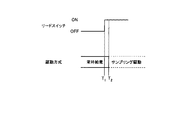
図4は、リードスイッチ13がオフ状態からオン状態に移行して停止した場合の給電方式を説明するタイミングチャートである。
時点T1まで、リードスイッチ13からの出力信号がオフ状態で停止していたときには、常時給電して、リードスイッチ13からの出力信号を監視する。
時点T1でリードスイッチ13からの出力信号に変化があったとき(オフからオンに変化)、停止確定判定時間を経過する時点T2まで出力信号に変化がないと、オン状態で停止したものとして、サンプリング給電の駆動に切り替えて、リードスイッチ13からの出力信号を監視する。
FIG. 4 is a timing chart for explaining a power feeding method when the
To the time T 1, when the output signal from the
When there is a change in the output signal from the
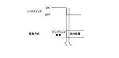
図5は、リードスイッチがオン状態からオフ状態に移行して停止した場合の給電方式を説明するタイミングチャートである。
時点T3までサンプリング給電を行って、この時点でリードスイッチ13の出力信号に変化があったとき(オンからオフに変化)、常時給電して、停止確定判定時間を経過する時点T4まで出力信号に変化がないと、オフ状態で停止したものとして、常時給電を維持して、リードスイッチ13からの出力信号を監視する。
FIG. 5 is a timing chart for explaining a power feeding method when the reed switch shifts from the on state to the off state and stops.
Performing sampling feed to the time T 3, (change from on to off) when there is a change in the output signal of the
以上のような構成により、リードスイッチがオフ状態で停止している場合、あるいは、リードスイッチがオン・オフのパルス信号を出力しているときには、常時給電を行うので、リードスイッチの変化への追従性を確保できる。
さらに、リードスイッチがオフ状態で停止している場合には電力が消費されないので常時給電を行い、リードスイッチがオン状態で停止しているときには電力が消費されるためサンプリング給電して間欠駆動するので、低消費電力とすることができる。
With the above configuration, when the reed switch is stopped in the off state, or when the reed switch is outputting an on / off pulse signal, power is always supplied, so the reed switch can follow changes. Can be secured.
Furthermore, when the reed switch is stopped in the off state, power is not consumed, so power is always supplied, and when the reed switch is stopped in the on state, power is consumed, so sampling power is fed and intermittent driving is performed. , Low power consumption can be achieved.
尚、本発明は上述した実施形態に限定されず、本発明の要旨を逸脱しない範囲内で各種の変形、修正が可能であるのは勿論である。 Note that the present invention is not limited to the above-described embodiment, and various modifications and corrections can be made without departing from the scope of the present invention.
10…流量計測部、11…給電ポート、12…検出ポート、13…リードスイッチ、14…回転体、15,15a,15b,15c,15d…磁石、16…プルアップ抵抗。
DESCRIPTION OF
Claims (1)
Priority Applications (1)
| Application Number | Priority Date | Filing Date | Title |
|---|---|---|---|
| JP2008189566A JP5106290B2 (en) | 2008-07-23 | 2008-07-23 | Flow measuring device |
Applications Claiming Priority (1)
| Application Number | Priority Date | Filing Date | Title |
|---|---|---|---|
| JP2008189566A JP5106290B2 (en) | 2008-07-23 | 2008-07-23 | Flow measuring device |
Publications (2)
| Publication Number | Publication Date |
|---|---|
| JP2010025841A true JP2010025841A (en) | 2010-02-04 |
| JP5106290B2 JP5106290B2 (en) | 2012-12-26 |
Family
ID=41731806
Family Applications (1)
| Application Number | Title | Priority Date | Filing Date |
|---|---|---|---|
| JP2008189566A Expired - Fee Related JP5106290B2 (en) | 2008-07-23 | 2008-07-23 | Flow measuring device |
Country Status (1)
| Country | Link |
|---|---|
| JP (1) | JP5106290B2 (en) |
Cited By (1)
| Publication number | Priority date | Publication date | Assignee | Title |
|---|---|---|---|---|
| US8918477B2 (en) | 2012-03-20 | 2014-12-23 | International Business Machines Corporation | Inter-domain replication of service information |
Citations (4)
| Publication number | Priority date | Publication date | Assignee | Title |
|---|---|---|---|---|
| JPH03239919A (en) * | 1990-02-16 | 1991-10-25 | Toshiba Corp | Gas flow rate meter |
| JPH1096655A (en) * | 1996-09-25 | 1998-04-14 | Toshiba Corp | Electron type water meter |
| JP2005111476A (en) * | 2001-12-28 | 2005-04-28 | Mitsubishi Rayon Co Ltd | Water purifier |
| JP2009198429A (en) * | 2008-02-25 | 2009-09-03 | Ricoh Elemex Corp | Flow measuring device |
-
2008
- 2008-07-23 JP JP2008189566A patent/JP5106290B2/en not_active Expired - Fee Related
Patent Citations (4)
| Publication number | Priority date | Publication date | Assignee | Title |
|---|---|---|---|---|
| JPH03239919A (en) * | 1990-02-16 | 1991-10-25 | Toshiba Corp | Gas flow rate meter |
| JPH1096655A (en) * | 1996-09-25 | 1998-04-14 | Toshiba Corp | Electron type water meter |
| JP2005111476A (en) * | 2001-12-28 | 2005-04-28 | Mitsubishi Rayon Co Ltd | Water purifier |
| JP2009198429A (en) * | 2008-02-25 | 2009-09-03 | Ricoh Elemex Corp | Flow measuring device |
Cited By (6)
| Publication number | Priority date | Publication date | Assignee | Title |
|---|---|---|---|---|
| US8918477B2 (en) | 2012-03-20 | 2014-12-23 | International Business Machines Corporation | Inter-domain replication of service information |
| US8930493B2 (en) | 2012-03-20 | 2015-01-06 | International Business Machines Corporation | Inter-domain replication of service information |
| US9313231B2 (en) | 2012-03-20 | 2016-04-12 | International Business Machines Corporation | Inter-domain replication of service information |
| US9866593B2 (en) | 2012-03-20 | 2018-01-09 | International Business Machines Corporation | Inter-domain replication of service information |
| US10116706B2 (en) | 2012-03-20 | 2018-10-30 | International Business Machines Corporation | Inter-domain replication of service information |
| US10715553B2 (en) | 2012-03-20 | 2020-07-14 | International Business Machines Corporation | Inter-domain replication of service information |
Also Published As
| Publication number | Publication date |
|---|---|
| JP5106290B2 (en) | 2012-12-26 |
Similar Documents
| Publication | Publication Date | Title |
|---|---|---|
| EP3422563B1 (en) | Motor drive control device, electric power steering device, and vehicle | |
| US8030877B2 (en) | Device and method for detecting back electromotive force phase and device and method for controlling excitation | |
| JP2009147778A (en) | Pulse signal generating apparatus, rotating machine, controller, and power window controller | |
| JPWO2014148087A1 (en) | Power steering device and control device for power steering device | |
| US8671773B2 (en) | Electronic flow meter | |
| JP2019176705A5 (en) | ||
| JP2009079925A (en) | Encoder for motor | |
| JP5106290B2 (en) | Flow measuring device | |
| JP2010145106A (en) | Stepping motor control circuit and analog electronic timepiece | |
| JP5184915B2 (en) | Flow measuring device | |
| KR102449059B1 (en) | Spool braking device | |
| JP2007309731A (en) | Clamp type ammeter | |
| JP3309884B2 (en) | Phase correction method for motor drive circuit | |
| JP2020005482A5 (en) | ||
| JP6322378B2 (en) | Detection device | |
| JP2019144080A (en) | Encoder and method for determining backup current abnormality | |
| JP4551192B2 (en) | Pendulum level detector | |
| JP2001344674A (en) | Gas alarm device and control method for gas sensor | |
| JPH1096655A (en) | Electron type water meter | |
| JP2006095453A (en) | Water purifier having electronic circuit | |
| JP2009288133A (en) | Stepping motor control circuit and analog electronic timepiece | |
| JP6510582B2 (en) | Motor drive control device, motor drive control method and tube pump | |
| JP2007159273A (en) | Pulse motor device | |
| KR20090106237A (en) | Apparatus of sensing a fulx | |
| JP2005233635A (en) | Gas shut-off device |
Legal Events
| Date | Code | Title | Description |
|---|---|---|---|
| A621 | Written request for application examination |
Free format text: JAPANESE INTERMEDIATE CODE: A621 Effective date: 20110627 |
|
| TRDD | Decision of grant or rejection written | ||
| A977 | Report on retrieval |
Free format text: JAPANESE INTERMEDIATE CODE: A971007 Effective date: 20120919 |
|
| A01 | Written decision to grant a patent or to grant a registration (utility model) |
Free format text: JAPANESE INTERMEDIATE CODE: A01 Effective date: 20120925 |
|
| A01 | Written decision to grant a patent or to grant a registration (utility model) |
Free format text: JAPANESE INTERMEDIATE CODE: A01 |
|
| A61 | First payment of annual fees (during grant procedure) |
Free format text: JAPANESE INTERMEDIATE CODE: A61 Effective date: 20121002 |
|
| R150 | Certificate of patent or registration of utility model |
Free format text: JAPANESE INTERMEDIATE CODE: R150 |
|
| FPAY | Renewal fee payment (event date is renewal date of database) |
Free format text: PAYMENT UNTIL: 20151012 Year of fee payment: 3 |
|
| LAPS | Cancellation because of no payment of annual fees |