JP2010025624A - Leakage prevention device for electrical apparatus - Google Patents
Leakage prevention device for electrical apparatus Download PDFInfo
- Publication number
- JP2010025624A JP2010025624A JP2008184827A JP2008184827A JP2010025624A JP 2010025624 A JP2010025624 A JP 2010025624A JP 2008184827 A JP2008184827 A JP 2008184827A JP 2008184827 A JP2008184827 A JP 2008184827A JP 2010025624 A JP2010025624 A JP 2010025624A
- Authority
- JP
- Japan
- Prior art keywords
- voltage
- inundation
- unit
- electrical
- leakage prevention
- Prior art date
- Legal status (The legal status is an assumption and is not a legal conclusion. Google has not performed a legal analysis and makes no representation as to the accuracy of the status listed.)
- Granted
Links
Images


Abstract
Description
この発明は、浸水による漏電を防止する電気機器の漏電防止装置に関するものである。 The present invention relates to a leakage prevention device for electrical equipment that prevents leakage due to water immersion.
電力変換装置などの高電圧の電気機器は、感電防止などの理由から、対地絶縁処理が施され、漏電を検出するための漏電検出回路が設けられている(例えば、特許文献1参照)。
このような漏電の原因の一つとして、電気機器内に水が浸入することがあげられる。このため、高電圧の電気機器には、防水構造が施されており、通常、水が入り込むことはない。 One of the causes of such electric leakage is that water enters the electric equipment. For this reason, a high-voltage electric device has a waterproof structure, and water does not normally enter.
しかしながら、防水構造が施された電気機器であっても、シール部材の劣化などにより浸水が生じるおそれがある。そして、万一浸水による漏電が生じると、電気機器の故障の原因となる。 However, even an electric device having a waterproof structure may be inundated due to deterioration of the sealing member. If a leakage occurs due to flooding, it may cause a failure of the electrical equipment.
本発明は上記課題に鑑みたものであり、浸水による漏電を防止することを目的とする。 The present invention has been made in view of the above problems, and an object thereof is to prevent leakage due to water immersion.
請求項1に記載の発明によれば、高圧電源から電力供給を受ける高圧回路部と、高圧電源より低い電圧の低圧電源から電力供給を受けて高圧回路部の制御を行う低圧回路部と、高圧回路部において高圧電流が流れる通電部のうち最も下方に位置する最下端通電部よりも下方の所定位置まで浸水したことを検出する浸水検出部と、最下端通電部よりも上方に配置された低圧回路部に接続され、浸水検出部からの信号に基づいて浸水の判断を行う浸水判断回路と、を備えることを特徴とする。 According to the first aspect of the present invention, the high-voltage circuit unit that receives power supply from the high-voltage power source, the low-voltage circuit unit that receives power supply from the low-voltage power source having a lower voltage than the high-voltage power source, and controls the high-voltage circuit unit; A submergence detecting unit for detecting that the submerged portion has flowed to a predetermined position below a lowermost end energizing portion among the energizing portions through which a high-voltage current flows in the circuit unit, and a low pressure disposed above the lowermost end energizing portion. An inundation determination circuit connected to the circuit unit and determining the inundation based on a signal from the inundation detection unit.
上記構成によれば、高圧回路部や低圧回路部の通電箇所に水が付着する前に、浸水を検出することができる。この結果、浸水による漏電が発生する前に、漏電防止に必要な措置を取ることができる。 According to the said structure, before water adheres to the energization location of a high voltage circuit part or a low voltage circuit part, flooding can be detected. As a result, it is possible to take measures necessary to prevent leakage before leakage due to flooding occurs.
請求項2に記載の発明によれば、浸水検出部は、互いに対向する2つの導電部材間に電位差を付与したことを特徴とする。 According to the second aspect of the present invention, the inundation detecting unit imparts a potential difference between two conductive members facing each other.
上記構成によれば、電位差が付与された導電部材間に水が介在した場合に、電位差が変化する。導電部材の電位の変化を測定することで、浸水を検出することができる。 According to the above configuration, the potential difference changes when water is interposed between the conductive members to which the potential difference is applied. By measuring the change in potential of the conductive member, it is possible to detect water intrusion.
請求項3に記載の発明によれば、対向する2つの導体部材の少なくとも一方は他方に向けて先端が細くなった尖端部となることを特徴とする。 According to the third aspect of the present invention, at least one of the two conductor members facing each other is a pointed end with a tip becoming narrower toward the other.
上記構成によれば、導電部材の先端に水滴が付着することを防止でき、水滴によって浸水を誤検出することを防止できる。 According to the said structure, it can prevent that a water droplet adheres to the front-end | tip of an electrically-conductive member, and can prevent misdetection of water immersion by a water droplet.
請求項4に記載の発明によれば、2つの導電部材間のうち距離が最小となる箇所に対して空気を送風する送風手段を備えることを特徴とする。 According to the invention described in claim 4, it is characterized in that it comprises air blowing means for blowing air to a portion where the distance is minimum between the two conductive members.
上記構成によれば、送風により、2つの導電部材間のうち距離が最小となる箇所に水滴が溜まることを防ぐことができ、水滴によって浸水を誤検出することを防止できる。 According to the said structure, it can prevent that a water droplet accumulates in the location where distance is the minimum between two electrically-conductive members by ventilation, and can prevent erroneously detecting water immersion by a water droplet.
請求項5に記載の発明によれば、導電部材を加熱する加熱手段を更に備えることを特徴とする。 According to a fifth aspect of the present invention, the apparatus further comprises heating means for heating the conductive member.
上記構成によれば、加熱手段が導電部材を加熱するため、導体部材間に水滴が溜まることを防止し、水滴によって浸水を誤検出することを防止できる。 According to the said structure, since a heating means heats a conductive member, it can prevent that a water droplet accumulates between conductor members, and can prevent erroneous detection of water immersion by a water droplet.
請求項6に記載の発明によれば、浸水判断回路は、信号の電圧又は電流が判定条件を満たしたときに浸水と判断することを特徴とする。 According to the invention described in claim 6, the inundation judgment circuit judges that the inundation occurs when the voltage or current of the signal satisfies the judgment condition.
請求項7に記載の発明によれば、浸水判断回路は、判定条件を所定期間内に所定回数満たすことを更に必要とすることを特徴とする。 According to the seventh aspect of the present invention, the inundation determination circuit further needs to satisfy the determination condition a predetermined number of times within a predetermined period.
上記構成によれば、所定期間内に所定回数閾値条件を満たしたときに、浸水と判断するため、誤検出防止できる。 According to the above configuration, when the threshold condition is satisfied a predetermined number of times within a predetermined period, it is determined that the water has been submerged, so that erroneous detection can be prevented.
(実施例1)
図1に、本発明に係る漏電防止装置を示す。
Example 1
FIG. 1 shows a leakage preventing apparatus according to the present invention.
漏電防止装置1は、高圧電源から電力供給を受ける高圧回路部11と、高圧電源よりも低い電圧の低圧電源12から電力供給を受ける低圧回路部13とに分けられる。高圧回路部11は、主に、パワーモジュール21、ドライブ基板22、コンデンサ23、高圧電源(図示せず)と接続される入力コネクタ24、パワーモジュール21によって電力変換された電力を出力する出力コネクタ25とからなる。パワーモジュール21は、複数のスイッチング素子26と、複数のスイッチング素子26を収容する樹脂ケース27からなる。高圧回路部11は、高圧電流が流れる通電部33を有しており、パワーモジュール21の通電部33は、通電部33のうち最も下方に位置する最下端通電部34を有している。スイッチング素子26は、台座部38の上に位置されており、台座部38の上に取り付けられた導電パターン(図示せず)に取り付けられている。最下端通電部34は、台座部38とスイッチング素子26との境界面に当たる。
The
入力コネクタ24を介して入力された高圧の直流電力は、コンデンサ23によって平滑化される。平滑化された直流電力は、ドライブ基板22からのゲート信号によって駆動するスイッチング素子で構成されるパワーモジュール21に入力され、交流に電力変換される。電力変換された交流電力は、出力コネクタを介してモータ(図示せず)に出力され、モータを駆動する。
The high-voltage DC power input through the
低圧回路部13を構成する制御基板31は最下端通電部34よりも上方に配置されており、ドライブ基板22に対して制御指令を送信する。ドライブ基板22は、制御指令に従ってスイッチング素子26に対してゲート信号を送信し、スイッチング素子26を駆動する。
The
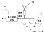
次に浸水検出部32について説明する。浸水検出部32の一端は制御基板31に組み込まれた浸水判断回路36に接続されている。また、浸水検出部32の他端はインバータケース35の底面に向かって延びており、その先端は導電部材が露出した検知部37となっている。この検知部37は、最下端通電部34よりも下方に位置している。浸水検出部32は、対向する2つの導電部材間、つまり浸水検出部32とケース35との間に電位差を付与している。本実施例では、図2に示すように、浸水検出部32は低圧電源12を備えているため、浸水検出部32はケース35よりも高電位となり、浸水検出部32とケース35との間に電位差が付与される。そして、浸水検出部32は、最下端通電部34よりも下方の所定位置まで浸水したことを検出し、浸水判断回路36に信号を送信する。浸水が起きていない通常時では、浸水検出部32は低圧電源12に基づいて電圧がHレベルの信号を浸水判断回路36に送信する。一方、図3のように、浸水が起きてケース35と検知部37が短絡する異常時では、浸水検出部32はケース35側に接地されることとなり、浸水検出部32は電圧がLレベルの信号を浸水判断回路36に送信する。
Next, the
次に、浸水判断回路36について説明する。浸水判断回路36は、浸水検出部32から送信される信号に基づき、浸水の有無を判断する。浸水判断回路36は、電圧がHレベルの信号を受け取った場合には正常、電圧がLレベルの信号を受け取った場合には浸水と判断する。本実施例では、浸水判断回路36への入力信号の電圧が所定の電圧以下となることを浸水の判定条件とする。なお、電圧ではなく電流を浸水の判定条件に用いてもよい。このように、浸水判断回路36は、信号の電圧又は電流が所定の判定条件を満たしたときに浸水と判断する。浸水判断回路36は、前記判定条件を所定期間内に所定回数満たした場合に、浸水と判断してもよい。複数回判定させることによって、誤検出の恐れを軽減することができる。
Next, the
なお、浸水判断回路36が浸水と判断した場合には、ECU(図示せず)に対してフェール信号を送信する。フェール信号を受け取ったECUは、漏電防止に必要な処置に移行する。
If the
このように、漏電防止装置1は、高圧回路部11や低圧回路部13が浸水する前に、浸水を検出するため、早期に漏電防止措置を施すことができる。
(実施例2)
図4の本発明の実施例2に係る漏電防止装置を示す。実施例2のインバータケース35は、左側の底面が、右側の底面よりも高くなっている。右側の底面にはコンデンサ23が配置され、左側の底面には、パワーモジュール21が配置される。パワーモジュールの上方に、ドライブ基板22が配置され、ドライブ基板22の上に制御基板31が配置される。左側の底面が高くなった結果、ドライブ基板22はコンデンサ23の上面よりも上方に位置し、出力コネクタ25は入力コネクタ24よりも上方に位置する点で、実施例1と相違する。パワーモジュール21を配置した底面は、コンデンサ23を配置した底面よりも高い位置にある。従って、実施例2においては、入力コネクタが有する通電部33のうち下方の通電部33が最下端通電部34となる。
As described above, since the
(Example 2)
FIG. 6 shows a leakage preventing apparatus according to Embodiment 2 of the present invention shown in FIG. In the
実施例2では、ケース側に浸水検出部32に向けて、先端が細くなった尖端部40を設けている。このように、対向する2つの導電部材のうち少なくとも一方は他方に向けて先端が細くなった尖端部40を持たせることで、対向する2つの導電部材間に水滴が付着することを防止できる。
(変形例)
漏電防止装置1は、2つの導電部材間のうち距離が最小となる箇所に対して送風を行う送風手段を持たせてもよい。送風手段としては、送風ファンがあげられる。
In the second embodiment, a pointed
(Modification)
The electric
更には、通電部材を加熱する加熱手段を備えてもよい。浸水検出部32や浸水検出部32と対向する導電部材を加熱することによって、余計な水分を除去できる。インバータなどでは通電した素子が動作して高熱となるため、そのような素子を加熱手段とし、加熱手段の近くに通電部材を配置してもよい。
Furthermore, you may provide the heating means which heats an electricity supply member. Excess water can be removed by heating the water
送風手段及び加熱手段により、結露による水滴などが浸水検出部32とケースとの間に付着して浸水と誤検出することを防止できる。
By the blowing means and the heating means, it is possible to prevent water droplets or the like due to dew condensation from adhering between the
浸水検出部32のうち、導電部材が露出する検知部37が酸化して腐食することによって、検知感度が低下することを防止するべく、導電部材の金属よりも酸化しにくい金属の薄膜で表面を被覆してもよい。
In order to prevent the
浸水検出部32の形状は、棒状の導体でもいいし、リード線等の振動しやすい導体にしてもよい。浸水検出部32を棒状の導体にした場合は、振動などによって、浸水検出部32が変位して周囲の導体と接地して誤検出する恐れが小さいという利点がある。一方、浸水検出部32をリード線などの振動体にすると、水滴が付着した場合でも、その水滴を振るい落とす等の効果が期待できる。この場合、周囲の機器等にリード線の端子部分が接地する恐れがあるので、リード線の端子部分を下方が開口する中空の絶縁体等によって、覆うことが望ましい。
The shape of the
1 漏電防止装置
11 高圧回路部
12 浸水判断回路
13 低圧回路部
32 浸水検出部
33 通電部
34 最下端通電部
36 浸水判定回路
40 尖端部
DESCRIPTION OF
Claims (7)
前記高圧回路部において高圧電流が流れる通電部のうち最も下方に位置する最下端通電部よりも下方の所定位置まで浸水したことを検出する浸水検出部と、
前記最下端通電部よりも上方に配置された前記低圧回路部に接続され、前記浸水検出部からの信号に基づいて浸水の判断を行う浸水判断回路と、
を備えることを特徴とする電気機器の漏電防止装置。 A high-voltage circuit unit that receives power supply from a high-voltage power source, and a low-voltage circuit unit that receives power supply from a low-voltage power source having a voltage lower than the high-voltage power source to control the high-voltage circuit unit;
An inundation detection unit for detecting that the submerged position is lower than a lowermost end energization unit among the energization units through which a high-voltage current flows in the high-voltage circuit unit;
An inundation determination circuit connected to the low-voltage circuit unit disposed above the lowest-end energization unit, and determining inundation based on a signal from the inundation detection unit;
An electrical leakage prevention apparatus for electrical equipment, comprising:
互いに対向する2つの導電部材間に電位差を付与した
ことを特徴とする請求項1記載の電気機器の漏電防止装置。 The inundation detection unit is
2. The leakage preventing device for an electric device according to claim 1, wherein a potential difference is applied between the two conductive members facing each other.
Priority Applications (1)
| Application Number | Priority Date | Filing Date | Title |
|---|---|---|---|
| JP2008184827A JP4973612B2 (en) | 2008-07-16 | 2008-07-16 | Electrical equipment leakage prevention device |
Applications Claiming Priority (1)
| Application Number | Priority Date | Filing Date | Title |
|---|---|---|---|
| JP2008184827A JP4973612B2 (en) | 2008-07-16 | 2008-07-16 | Electrical equipment leakage prevention device |
Publications (2)
| Publication Number | Publication Date |
|---|---|
| JP2010025624A true JP2010025624A (en) | 2010-02-04 |
| JP4973612B2 JP4973612B2 (en) | 2012-07-11 |
Family
ID=41731612
Family Applications (1)
| Application Number | Title | Priority Date | Filing Date |
|---|---|---|---|
| JP2008184827A Expired - Fee Related JP4973612B2 (en) | 2008-07-16 | 2008-07-16 | Electrical equipment leakage prevention device |
Country Status (1)
| Country | Link |
|---|---|
| JP (1) | JP4973612B2 (en) |
Cited By (4)
| Publication number | Priority date | Publication date | Assignee | Title |
|---|---|---|---|---|
| WO2012093678A1 (en) * | 2011-01-04 | 2012-07-12 | 株式会社ジェイテクト | Electric pump apparatus |
| JP2013223330A (en) * | 2012-04-16 | 2013-10-28 | Toyota Motor Corp | On-board battery device |
| JP2015053830A (en) * | 2013-09-09 | 2015-03-19 | 株式会社デンソー | Power conversion device |
| JP2020067364A (en) * | 2018-10-24 | 2020-04-30 | 住友電装株式会社 | Electric apparatus |
Citations (6)
| Publication number | Priority date | Publication date | Assignee | Title |
|---|---|---|---|---|
| JPH05164649A (en) * | 1991-12-18 | 1993-06-29 | Kawasaki Steel Corp | Method for preventing erroneous operation of leakage sensor |
| JPH0746702A (en) * | 1993-07-30 | 1995-02-14 | Denshi Giken:Kk | Leak preventing device for electric automobile |
| JP2000205989A (en) * | 1999-01-11 | 2000-07-28 | Harness Syst Tech Res Ltd | Wet sensor and joint box having the same |
| JP2002236072A (en) * | 2001-02-09 | 2002-08-23 | Harman Kikaku:Kk | Water leakage detecting device |
| JP2005145101A (en) * | 2003-11-11 | 2005-06-09 | Omron Corp | Drive device |
| JP2007057490A (en) * | 2005-08-26 | 2007-03-08 | Denso Corp | Electrical leak detector of on-vehicle ground insulation circuit |
-
2008
- 2008-07-16 JP JP2008184827A patent/JP4973612B2/en not_active Expired - Fee Related
Patent Citations (6)
| Publication number | Priority date | Publication date | Assignee | Title |
|---|---|---|---|---|
| JPH05164649A (en) * | 1991-12-18 | 1993-06-29 | Kawasaki Steel Corp | Method for preventing erroneous operation of leakage sensor |
| JPH0746702A (en) * | 1993-07-30 | 1995-02-14 | Denshi Giken:Kk | Leak preventing device for electric automobile |
| JP2000205989A (en) * | 1999-01-11 | 2000-07-28 | Harness Syst Tech Res Ltd | Wet sensor and joint box having the same |
| JP2002236072A (en) * | 2001-02-09 | 2002-08-23 | Harman Kikaku:Kk | Water leakage detecting device |
| JP2005145101A (en) * | 2003-11-11 | 2005-06-09 | Omron Corp | Drive device |
| JP2007057490A (en) * | 2005-08-26 | 2007-03-08 | Denso Corp | Electrical leak detector of on-vehicle ground insulation circuit |
Cited By (7)
| Publication number | Priority date | Publication date | Assignee | Title |
|---|---|---|---|---|
| WO2012093678A1 (en) * | 2011-01-04 | 2012-07-12 | 株式会社ジェイテクト | Electric pump apparatus |
| JPWO2012093678A1 (en) * | 2011-01-04 | 2014-06-09 | 株式会社ジェイテクト | Electric pump device |
| JP5994638B2 (en) * | 2011-01-04 | 2016-09-21 | 株式会社ジェイテクト | Electric pump device |
| JP2013223330A (en) * | 2012-04-16 | 2013-10-28 | Toyota Motor Corp | On-board battery device |
| JP2015053830A (en) * | 2013-09-09 | 2015-03-19 | 株式会社デンソー | Power conversion device |
| JP2020067364A (en) * | 2018-10-24 | 2020-04-30 | 住友電装株式会社 | Electric apparatus |
| JP7001039B2 (en) | 2018-10-24 | 2022-01-19 | 住友電装株式会社 | Electrical equipment |
Also Published As
| Publication number | Publication date |
|---|---|
| JP4973612B2 (en) | 2012-07-11 |
Similar Documents
| Publication | Publication Date | Title |
|---|---|---|
| US6683535B1 (en) | Water detection system and method | |
| JP4973612B2 (en) | Electrical equipment leakage prevention device | |
| CN106249123B (en) | Corrosion detection circuit and motor drive device | |
| JP2016193140A5 (en) | ||
| JP2017023301A5 (en) | ||
| JP2017029246A5 (en) | ||
| US9669733B2 (en) | Self-insulated modular power supply line | |
| US9403497B2 (en) | Transmission devices and method for transmitting an electric current to a component of a steering wheel of a motor vehicle | |
| JP2017018366A5 (en) | ||
| US20150288036A1 (en) | Electrical Accumulator with Water Sensor | |
| JP2001251026A (en) | Control board | |
| CN101371364A (en) | Sensor for detecting organic liquids | |
| JP2002188977A (en) | Detection device of liquid penetration or liquid level | |
| JPH10303589A (en) | Method for preventing, reducing, and removing influence of moisture on one or plurality of electronic construction groups having moisture influence preventing means | |
| JP2008117581A (en) | Submerged electric heater | |
| US7557724B2 (en) | Device for detecting a fault current in an electronic apparatus | |
| KR102486475B1 (en) | Apparatus and method of sensing liquid inflow for electronic control unit | |
| JP2013220778A (en) | Use environment warning system | |
| CA2994559C (en) | Enhanced liquid detection mechanisms for circuit cards | |
| JP2003089354A (en) | Wiring connection container having inside accumulated water detection function | |
| JP2001228008A (en) | Drainage with water level detector | |
| US20230324320A1 (en) | Electrical system and method for determining a potential functional impairment in the electrical system | |
| JP2009284195A (en) | Electric equipment and driving method therefor | |
| US9614362B2 (en) | Overcurrent protection device | |
| JP6422638B2 (en) | Power converter |
Legal Events
| Date | Code | Title | Description |
|---|---|---|---|
| A621 | Written request for application examination |
Free format text: JAPANESE INTERMEDIATE CODE: A621 Effective date: 20100906 |
|
| A131 | Notification of reasons for refusal |
Free format text: JAPANESE INTERMEDIATE CODE: A131 Effective date: 20111108 |
|
| A521 | Written amendment |
Free format text: JAPANESE INTERMEDIATE CODE: A523 Effective date: 20111221 |
|
| TRDD | Decision of grant or rejection written | ||
| A01 | Written decision to grant a patent or to grant a registration (utility model) |
Free format text: JAPANESE INTERMEDIATE CODE: A01 Effective date: 20120313 |
|
| A01 | Written decision to grant a patent or to grant a registration (utility model) |
Free format text: JAPANESE INTERMEDIATE CODE: A01 |
|
| A61 | First payment of annual fees (during grant procedure) |
Free format text: JAPANESE INTERMEDIATE CODE: A61 Effective date: 20120326 |
|
| FPAY | Renewal fee payment (event date is renewal date of database) |
Free format text: PAYMENT UNTIL: 20150420 Year of fee payment: 3 |
|
| R250 | Receipt of annual fees |
Free format text: JAPANESE INTERMEDIATE CODE: R250 |
|
| R250 | Receipt of annual fees |
Free format text: JAPANESE INTERMEDIATE CODE: R250 |
|
| R250 | Receipt of annual fees |
Free format text: JAPANESE INTERMEDIATE CODE: R250 |
|
| LAPS | Cancellation because of no payment of annual fees |