JP2010025521A - Heat exchanger and manufacturing method therefor - Google Patents
Heat exchanger and manufacturing method therefor Download PDFInfo
- Publication number
- JP2010025521A JP2010025521A JP2008190946A JP2008190946A JP2010025521A JP 2010025521 A JP2010025521 A JP 2010025521A JP 2008190946 A JP2008190946 A JP 2008190946A JP 2008190946 A JP2008190946 A JP 2008190946A JP 2010025521 A JP2010025521 A JP 2010025521A
- Authority
- JP
- Japan
- Prior art keywords
- heat exchanger
- fins
- protrusions
- plate
- fin
- Prior art date
- Legal status (The legal status is an assumption and is not a legal conclusion. Google has not performed a legal analysis and makes no representation as to the accuracy of the status listed.)
- Granted
Links
Images


Classifications
-
- B—PERFORMING OPERATIONS; TRANSPORTING
- B21—MECHANICAL METAL-WORKING WITHOUT ESSENTIALLY REMOVING MATERIAL; PUNCHING METAL
- B21D—WORKING OR PROCESSING OF SHEET METAL OR METAL TUBES, RODS OR PROFILES WITHOUT ESSENTIALLY REMOVING MATERIAL; PUNCHING METAL
- B21D53/00—Making other particular articles
- B21D53/02—Making other particular articles heat exchangers or parts thereof, e.g. radiators, condensers fins, headers
- B21D53/04—Making other particular articles heat exchangers or parts thereof, e.g. radiators, condensers fins, headers of sheet metal
-
- F—MECHANICAL ENGINEERING; LIGHTING; HEATING; WEAPONS; BLASTING
- F28—HEAT EXCHANGE IN GENERAL
- F28F—DETAILS OF HEAT-EXCHANGE AND HEAT-TRANSFER APPARATUS, OF GENERAL APPLICATION
- F28F13/00—Arrangements for modifying heat-transfer, e.g. increasing, decreasing
- F28F13/06—Arrangements for modifying heat-transfer, e.g. increasing, decreasing by affecting the pattern of flow of the heat-exchange media
-
- F—MECHANICAL ENGINEERING; LIGHTING; HEATING; WEAPONS; BLASTING
- F28—HEAT EXCHANGE IN GENERAL
- F28F—DETAILS OF HEAT-EXCHANGE AND HEAT-TRANSFER APPARATUS, OF GENERAL APPLICATION
- F28F3/00—Plate-like or laminated elements; Assemblies of plate-like or laminated elements
- F28F3/02—Elements or assemblies thereof with means for increasing heat-transfer area, e.g. with fins, with recesses, with corrugations
-
- F—MECHANICAL ENGINEERING; LIGHTING; HEATING; WEAPONS; BLASTING
- F28—HEAT EXCHANGE IN GENERAL
- F28F—DETAILS OF HEAT-EXCHANGE AND HEAT-TRANSFER APPARATUS, OF GENERAL APPLICATION
- F28F3/00—Plate-like or laminated elements; Assemblies of plate-like or laminated elements
- F28F3/12—Elements constructed in the shape of a hollow panel, e.g. with channels
-
- H—ELECTRICITY
- H01—ELECTRIC ELEMENTS
- H01L—SEMICONDUCTOR DEVICES NOT COVERED BY CLASS H10
- H01L23/00—Details of semiconductor or other solid state devices
- H01L23/34—Arrangements for cooling, heating, ventilating or temperature compensation ; Temperature sensing arrangements
- H01L23/46—Arrangements for cooling, heating, ventilating or temperature compensation ; Temperature sensing arrangements involving the transfer of heat by flowing fluids
- H01L23/473—Arrangements for cooling, heating, ventilating or temperature compensation ; Temperature sensing arrangements involving the transfer of heat by flowing fluids by flowing liquids
-
- H—ELECTRICITY
- H01—ELECTRIC ELEMENTS
- H01L—SEMICONDUCTOR DEVICES NOT COVERED BY CLASS H10
- H01L2924/00—Indexing scheme for arrangements or methods for connecting or disconnecting semiconductor or solid-state bodies as covered by H01L24/00
- H01L2924/0001—Technical content checked by a classifier
- H01L2924/0002—Not covered by any one of groups H01L24/00, H01L24/00 and H01L2224/00
Abstract
Description
本発明は、平行に並べられた複数の直線形状のフィンによって流路が形成され、その流路に冷媒を流すことによって発熱体からの熱を放散させる熱交換器に関し、特に、放熱効果を高める冷媒の流れを生じさせる流路をもった熱交換器及びその製造方法に関する。 The present invention relates to a heat exchanger in which a flow path is formed by a plurality of linear fins arranged in parallel and dissipates heat from a heating element by flowing a refrigerant through the flow path. The present invention relates to a heat exchanger having a flow path for generating a refrigerant flow and a manufacturing method thereof.
ハイブリッド自動車等には、モータを駆動するインバータに半導体素子が用いられており、それを冷却する水冷式の熱交換器が採用されている。半導体素子を搭載するインバータは、より高出力が求められる一方で小型化や軽量化の要求が厳しくなってきているため、放熱効果に優れた熱交換器が求められている。下記特許文献1には、冷却性能を向上させた従来の熱交換器が記載されている。図16は、同文献に記載された熱交換器を平面方向に見た断面図である。
A hybrid vehicle or the like uses a semiconductor element for an inverter that drives a motor, and employs a water-cooled heat exchanger that cools the semiconductor element. Inverters equipped with semiconductor elements are required to have higher output, while demands for miniaturization and weight reduction have become stricter. Therefore, a heat exchanger having an excellent heat dissipation effect is required. The following
熱交換器100は、供給ポート102と排出ポート103が形成されたケース101内に、その供給ポート102から排出ポート103へと流れる冷媒の流路が構成されている。この熱交換器100では、複数のフィン111によって流路が形成され、更に流路は直線方向に3分割された第1、第2、第3フィン群201,202,203が構成されている。フィン群201〜203は、いずれも横方向に複数のフィン111が平行に配置され、フィン群201〜203同士では、フィン111が同一直線上にあって、これにより直線流路が複数形成されている。ただし、その直線流路は各フィン群201〜203の間で途切れ、合流部105,106が形成されている。
In the
また、熱交換器100には、横に並んだ複数のフィン111の間に隔離フィン112,112が設けられ、フィン111同士よりも広い流路107が形成されている。なお、第3フィン群203では、隣り合う離隔フィン112同士がつながって流路を閉じている。こうした熱交換器100には、合流部105,106および離隔フィン112による離隔流路107によって区切られた9区画に、発熱体である半導体素子300がそれぞれ配置されている。こうした熱交換器100では、供給ポート102から流入した冷媒がフィン111による直線流路を流れ、合流部105,106で混ざり合って流量配分を均一にしながら、更に下流へと分岐して流れる。
ところで、フィンによって構成される流路が熱交換器100にように直線である場合、冷媒の流れは層流になってしまう。そのため、流路中央部分では流れが速くなる一方、フィン111と接触する境界層では流れが遅くなってしまい、フィンに伝えられた発熱体の熱は放散され難く、冷却性能が上がらないという問題があった。この点、冷媒がフィンからの熱を効率よく放散させるには、冷媒の流れを乱して境界層を破壊することが有効であると考えられる。しかし、熱交換器100のように合流部105,106による横流路では十分ではなかった。
By the way, when the flow path constituted by the fins is a straight line like the
近年、半導体素子の小型化によって発熱密度が増大し、インバータなどに使用される熱交換器に対して冷却性能の向上が求められ、フィンをオフセットさせるなどした流路の熱交換器が提案されている。しかし、そうした熱交換器は、加工が複雑になってコストを上げてしまう問題があった。特に、鋳造などによってフィン部材を形成する場合、加工コストがかかって熱交換器自身が高価なものになってしまう他、フィンの微細加工が困難なため冷却性能の向上も望めなかった。 In recent years, the heat generation density has increased due to the miniaturization of semiconductor elements, and improvement in cooling performance has been demanded for heat exchangers used in inverters, etc., and heat exchangers with flow paths such as offsetting fins have been proposed. Yes. However, such a heat exchanger has a problem that the processing becomes complicated and the cost increases. In particular, when the fin member is formed by casting or the like, the processing cost is high and the heat exchanger itself becomes expensive, and it is difficult to finely process the fin, so that the cooling performance cannot be improved.
そこで、本発明は、かかる課題を解決すべく、発熱体を効率よく冷却する新たな構造の熱交換器及びその製造方法を提供することを目的とする。 Accordingly, an object of the present invention is to provide a heat exchanger having a new structure for efficiently cooling a heating element and a method for manufacturing the same in order to solve such a problem.
本発明に係る熱交換器は、直線状に形成された複数の起立したフィンが一定の間隔をあけて平行に並べられ、隣り合うフィン同士の隙間が当該フィンの起立方向の上下に配置された上板及び下板によって閉じられてできた複数の流路を有するものであって、前記上板及び下板の一方又は双方には、前記流路内に突き出る突起が、前記各流路の長手方向に複数形成されたものであることを特徴とする。
また、本発明に係る熱交換器は、前記上板又は下板の一方を構成するベースに対して前記複数のフィンが一体に形成されたフィン部材と、前記ベースの反対側から前記フィンに対して接合される前記上板又は下板の他方を構成する当板とを有し、そのベース又は当板に対して前記突起が形成されたものであることが好ましい。
In the heat exchanger according to the present invention, a plurality of standing fins formed in a straight line are arranged in parallel with a certain interval, and gaps between adjacent fins are arranged above and below in the standing direction of the fins. A plurality of flow paths are formed by being closed by an upper plate and a lower plate, and one or both of the upper plate and the lower plate have protrusions protruding into the flow paths in the length of each flow path. It is characterized by being formed in plural in the direction.
The heat exchanger according to the present invention includes a fin member in which the plurality of fins are integrally formed with respect to a base constituting one of the upper plate and the lower plate, and the fin from the opposite side of the base. It is preferable that the upper plate or the lower plate to be joined together is formed, and the protrusions are formed on the base or the lower plate.
また、本発明の熱交換器は、前記フィン部材が押出成形によって形成されたものであることが好ましい。
また、本発明に係る熱交換器は、前記突起がプレス加工によって形成されたものであることが好ましい。
また、本発明に係る熱交換器は、前記流路の長手方向に前後する突起が、当該突起の間で生じる冷却性能の低下が、所定の基準値を下回らないようにした間隔で配置されたものであることが好ましい。
また、本発明に係る熱交換器は、前記複数の突起を前記流路と直交する方向に見た場合に、隣り合う流路に形成された突起が千鳥状に配置されたものであることが好ましい。
In the heat exchanger of the present invention, the fin member is preferably formed by extrusion.
In the heat exchanger according to the present invention, the protrusion is preferably formed by press working.
Further, in the heat exchanger according to the present invention, the protrusions moving back and forth in the longitudinal direction of the flow path are arranged at intervals such that the decrease in cooling performance generated between the protrusions does not fall below a predetermined reference value. It is preferable.
Further, in the heat exchanger according to the present invention, when the plurality of protrusions are viewed in a direction orthogonal to the flow path, the protrusions formed in adjacent flow paths may be arranged in a staggered manner. preferable.
一方、本発明に係る熱交換器の製造方法は、直線状に形成された複数の起立したフィンが一定の間隔をあけて平行に並べられ、隣り合うフィン同士の隙間が当該フィンの起立方向の上下に配置された上板及び下板によって閉じられてできた複数の流路を有する熱交換器を製造するための製造方法であって、前記上板又は下板の一方を構成するベースに対して前記複数のフィンが起立したフィン部材を押出成形によって形成するフィン部材加工工程と、前記フィン部材のベース、又は前記上板若しくは下板の他方を構成する当板に対し、プレスによって前記複数の突起を形成する突起形成工程と、前記ベースの反対側から前記フィンに対して前記当板を当てて接合する接合工程とを有することを特徴とする。 On the other hand, in the method for manufacturing a heat exchanger according to the present invention, a plurality of standing fins formed in a straight line are arranged in parallel with a certain interval, and a gap between adjacent fins is in the standing direction of the fin. A manufacturing method for manufacturing a heat exchanger having a plurality of flow paths closed by an upper plate and a lower plate arranged above and below, with respect to a base constituting one of the upper plate and the lower plate The fin member processing step of forming the fin member with the plurality of fins upright by extrusion molding, and the base plate of the fin member or the contact plate constituting the other of the upper plate or the lower plate by pressing A projection forming step for forming a projection and a joining step for joining the fin against the fin from the opposite side of the base.
また、本発明に係る熱交換器の製造方法は、前記突起形成工程において、前記ベース又は当板に対して流路面の反対側からパンチが圧入され、流路面側に素材が押し出されて前記突起が形成されることが好ましい。
また、本発明に係る熱交換器の製造方法は、前記突起形成工程でベースに対して突起を形成する場合、隣り合うフィン同士の隙間に板状の支持部材を挿入してフィンを支持することが好ましい。
また、本発明に係る熱交換器の製造方法は、前記フィン部材加工工程において、隣り合うフィン同士の隙間に前記押出し方向に連続した凸部を有するフィン部材を形成し、前記突起形成工程では、前記押出し方向に分割形成されたプレス板が前記隙間に挿入され、分割部分を残して前記凸部を押し潰して前記突起を形成することが好ましい。
Further, in the method of manufacturing a heat exchanger according to the present invention, in the protrusion forming step, a punch is pressed into the base or the plate from the opposite side of the flow path surface, and the material is pushed out to the flow path surface side, thereby the protrusion. Is preferably formed.
Further, in the method of manufacturing a heat exchanger according to the present invention, when the protrusion is formed on the base in the protrusion forming step, a plate-like support member is inserted into a gap between adjacent fins to support the fin. Is preferred.
Further, in the method of manufacturing a heat exchanger according to the present invention, in the fin member processing step, a fin member having a convex portion continuous in the extrusion direction is formed in a gap between adjacent fins. It is preferable that a press plate divided and formed in the extrusion direction is inserted into the gap, and the protrusions are crushed to leave the divided portions to form the protrusions.
よって、本発明の熱交換器によれば、流路を流れる冷媒が突起によって流れが乱され、フィンと接する境界層を破壊するので、フィンから熱を奪った冷媒が停滞することなく下流へとスムーズに流れことによって冷却性能が向上する。従って、小型の発熱体によって発熱密度が増大したとしても、従来に比べて冷却性能の向上がしたことで対応が可能になる。また、直線のフィンからなる流路に突起を設けるだけの熱交換器は、その構成及び加工が単純化され、加工コストを抑えることができる。特に、フィン部材を押出成形によって形成し、そのベースや当板にプレスによって突起を形成する製造方法をとることで、量産化が可能になり、熱交換器を安価に提供することが可能になる。 Therefore, according to the heat exchanger of the present invention, the refrigerant flowing in the flow path is disturbed by the protrusions and destroys the boundary layer in contact with the fins, so that the refrigerant deprived of heat from the fins goes downstream without stagnation. Cooling performance improves by flowing smoothly. Therefore, even if the heat generation density is increased by a small heating element, it is possible to cope with the improvement of the cooling performance as compared with the conventional case. Moreover, the heat exchanger which only provides a protrusion in the flow path which consists of a linear fin can simplify the structure and process, and can suppress process cost. In particular, by adopting a manufacturing method in which the fin member is formed by extrusion molding and the protrusion is formed on the base or the plate by pressing, mass production becomes possible, and a heat exchanger can be provided at low cost. .
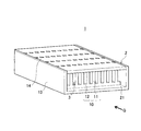
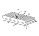
次に、本発明に係る熱交換器及びその製造方法の一実施形態について図面を参照しながら以下に説明する。図1は、本実施形態の熱交換器を示した斜視図である。
この熱交換器1は、筒状に形成された本体2内に複数のフィン11が配置され、本体2の流入側開口部21から、反対の排出側開口部へと連通した複数の流路3が形成されている。熱交換器1の本体2は、例えば矢印Qで示す方向から冷媒が流し込まれるものであり、その流入側開口部21から、反対の排出側開口部へと貫通している。
Next, an embodiment of a heat exchanger and a manufacturing method thereof according to the present invention will be described below with reference to the drawings. FIG. 1 is a perspective view showing a heat exchanger according to the present embodiment.
In this
なお、図1には、本体2に流入側開口部21と反対側の排出側開口部とが大きく開口した熱交換器1が示されているが、使用時には閉じた状態でそれぞれが不図示の冷媒供給管または冷媒排出管に接続される。そして、冷媒供給管には、冷媒を熱交換器1に対して一定の圧力で送り込む供給ポンプが接続され、冷媒排出管には、熱交換器1から排出された冷媒を回収するタンクが接続される。
FIG. 1 shows the
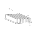
ところで、本実施形態の熱交換器1は、断面がコの字の受フレーム13に対し、図面上方の解放側に当板14が嵌め合わされ、筒形状の本体2が形成されている。そして、本体2の中には、複数の流路3を構成するフィン部材10が挿入されている。ここで、図2は、図1に示す熱交換器1から受フレーム13を外した構造を示した斜視図であり、図3は、更に当板14を外したフィン部材10を示した斜視図である。
Incidentally, in the
フィン部材10は、ベース12上に複数のフィン11が突設して一体に形成されたものでる。ベース12は矩形の平板であり、それに対して複数のフィン11が直交方向に起立して形成されている。複数のフィン11は、全てが同じ高さであって、且つベース12の寸法と等しい長さで形成され、隣り合うもの同士が平行に並べられている。こうしたフィン部材10は、受フレーム13内にガタ無く入れられ、そのフィン11の先端に突き当てられるように当板14が被せられる。熱交換器1は、組み付けられたフィン部材10、受フレーム13及び当板14が溶接によって接合されて一体になっている。
The
この熱交換器1には、こうして隣り合うフィン11同士の隙間が下板のベース12と上板の当板14によって囲まれ、平行な複数の流路3が構成されている。なお、フィン部材10の両端に位置するフィン11は、受フレーム13の起立した壁板との間に隙間を形成し、その隙間がベース12と当板14によって囲まれた流路3となっている。
In this
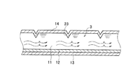
そこで、熱交換器1に対し図1の矢印Qで示す方向から冷媒が流し込まれると、その流入側開口部21から本体2内に入った冷媒は、フィン11によって仕切られた各流路3に分かれて流れる。ところで、本実施形態の熱交換器1は、フィン11によって形成された流路3が直線流路であるため、そのままでは前記従来例と同様に冷媒の流れが層流になってしまい、十分な冷却能力を発揮させることができない。そこで、本実施形体の熱交換器1では、冷媒の流れを乱す構成が流路3内に設けられている。すなわち、流路3を構成する当板14に対して突起23が形成され、それが流路3内を流れる冷媒の障害物となっている。
Therefore, when the refrigerant flows into the
突起23は、当板14に形成された図2に示す穴25の反対側に存在し、当板14の縦方向及び横方向に所定の間隔で複数形成されている。具体的には、当板14が図1に示すように熱交換器1として組み立てられた際、隣り合うフィン11の間に入り込み、1本の流路3内に一定の間隔で複数の突起が存在するように形成されている。
The
ここで図4は、ある流路3内における冷媒の流れを模式的に示した図である。フィン11によって構成される流路3は直線であるため、そのままであれば冷媒の流れが層流になり、従来と同様の問題が生じる。しかし、本実施形態では、突起23が存在することによって冷媒の流れが乱され、層流の際に生じるフィン11と接触する境界層が破壊され、フィン11の熱を効率良く放散することを可能にしている。
Here, FIG. 4 is a diagram schematically showing the flow of the refrigerant in a
そして、特に本実施形態の熱交換器1では、冷却性能を維持するため、一つの流路3内に複数形成された突起23が特定の間隔で配置されている。図5は、流路3内に冷媒を流して行った、冷却性能試験の結果を示したグラフである。横軸には流路3内のある範囲を取り出して示した流路位置を示し、縦軸には冷却性能(熱伝達率)を示している。横軸に示した流路位置p1,p2,p3が突起23の存在する位置であり、冷媒はp1からp3の方向に流れている。
And especially in the
図5のグラフからは、流路3を冷媒が流れることによる冷却性能が、一定ではなく波形に変化し、流路内の位置によって熱伝達率が異なることが分かる。特にグラフkは、突起23が存在するp1,p2,p3の手前から上昇し始め、その直後でピーク値を得るが、その後徐々に下降している。これは、突起23によって冷媒の流れが乱され、その冷媒がフィン11から熱を奪って効率良く流れるからであり、一方で、突起23から離れるに従って冷媒の流れが再び層流へと近づき、フィン11との境界層の流れが停滞し易くなるからであると考えられる。
From the graph of FIG. 5, it can be seen that the cooling performance due to the refrigerant flowing through the
そこで本実施形態では、発熱体の熱を放散させるのに要求される冷却能力を基準値sとして設定し、それ以下に熱伝達率が下がらないように突起23の位置が決定されている。つまり、流路3の長手方向に並んだ複数の突起23は、グラフkで示される熱伝達率の値が基準値sを下回る手前で上昇するように、突起23同士の距離が決められている。なお、突起23同士の距離は、流路3の大きさや冷媒の供給流量、突起23の高さ、或いは発熱体の発熱量などによって変化する。なお、突起23は、冷媒の流れを妨げて圧損を生じさせるものでもあるため、供給ポンプの能力などを考慮し、本実施形態では流路3の高さの1/3で形成されている。
Therefore, in the present embodiment, the cooling capacity required to dissipate the heat of the heating element is set as the reference value s, and the position of the
次に、こうした熱交換器1は、使用に当たって、例えば図6に示すように熱拡散のためのヒートスプレッダ6が当板14に貼り付けられ、その上に発熱体である複数の半導体素子7が整然と並べて貼り付けられる。そして、インバータなどに使用される半導体素子7が発熱すると、その熱はヒートスプレッダ6に伝わって拡散され、更に本体2から内部のフィン11へと伝えられる。本体2内には流入側開口部21から冷媒が供給され、反対の排出側開口部へと流れている。従って、フィン11に伝えられた熱は、そのフィン11に接しながら流れる冷媒によって奪われ、放熱が実行される。
Next, in use of such a
このとき流路3を流れる冷媒は、突起23によって流れが乱され、フィン11と接する境界層が破壊される。突起23が所定の間隔で配置されているため、流路3内では常に冷媒が攪拌された状態で流れ、熱を奪った冷媒が効率良く下流へと流され、特に、図5に示すように冷却性能が基準値s以上で維持されている。
そのため、熱交換器1によれば、半導体素子7が小型化して発熱密度が増大したとしても、従来に比べて冷却能力が格段に向上したことにより対応が可能になった。また、直線のフィン11からなる流路3に突起23を設けるだけの熱交換器1は、その構成が単純であり、部品点数も少なくなったことでコストを抑えることが可能になった。
At this time, the coolant flowing in the
Therefore, according to the
更に、本実施形態では、こうした冷却効果の高い熱交換器1の製造に当たり、その加工コストを低減し、熱交換器1自身を安価に提供することを可能にした。そこで次に、熱交換器1の製造方法について説明する。
先ず、熱交換器1を構成するフィン部材10は押出成形によって形成される。フィン部材10には、熱伝達率の良いアルミが材料として使用され、融解した材料が複数のフィン11やベース12を一体成形する成形型から押し出され、例えば数mの長さのロングフィン部材が形成される。ここで、図7は、フィン部材10の加工工程の一部を示した概念図である。
Furthermore, in this embodiment, in manufacturing the
First, the
押出成形されたロングフィン部材10Lは、押出成形直後にそのまま図示するプレス装置に搬送されて切断される。ロングフィン部材10Lは、ロングベース12Lに対してロングフィン11Lが起立した状態で一体成形され、その後、その状態のまま図示するように押出し方向Fへと搬送される。押出成形された成形直後のロングフィン部材10Lは、材料がある程度熱をもっているため依然として柔らかく、その状態で切断用プレス装置50へと送られて切断が行われる。
The extruded
切断用プレス装置50は、ロングベース12Lを下方で支える不図示の下型と、押出し方向Fに直交して配置され、下型に向けて下ろされる板状の上型51とが設けられている。上型51は、一定の厚みをもった平板であって下端が平らに形成されている。そして、上型51の押圧力によってフィン11が座屈したり倒れてしまわないように、上型51を挟んで一対のフィン抑え治具53,53が設けられている。フィン抑え治具53,53は、複数あるフィン11の間に入り込むように板状の支持突起55が複数形成されている。
The cutting
そこで、押出成形によって形成されたロングフィン部材10Lは、途中で搬送が一旦止められる。そして、そのロングフィン部材10Lに対し、そのロングフィン11L同士の隙間にフィン抑え治具53,53の支持突起55が挿入され、1枚毎にロングフィン11Lが両面側から支えられる。次いで、フィン抑え治具53,53の間を上型51が下降し、それによって複数のロングフィン11Lが一度に切断され、更にロングベース12Lも同じ位置で切断される。この切断工程では、このような切断が長尺のロングフィン部材10Lに対して一定間隔で行われ、複数のフィン部材10が連続して取り出される。なお、受フレーム13も同じように押出成形と切断によって形成される。
Therefore, the
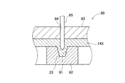
次に、当板14の加工について説明する。当板14は、一定厚のアルミ板から所定の大きさに切り出された平板に対し、複数の突起23が所定の位置に形成されたものである。そして、その平板に対する突起23の形成がプレス加工によって行われる。図8は、突起を形成するための突起用プレス装置を示した断面図である。
ところで、熱交換器1の突起23は三角形をしているが、その機能を果たすものであれば突起23の形状は限定されない。図8で示す突起用プレス装置60で形成される突起は円柱状であって形状が異なるが、ここでは図2に示すものと同じく突起23として説明する。
Next, processing of the
By the way, although the
突起用プレス装置60は、平板14Xを挟んだ下方の受け型にはダイス62が設けられ、そのダイス62には断面円形のダイス孔61が形成されている。一方、上方の押し型には、不図示のバネによって平板14Xを押さえ付けるストッパー63が設けられ、そのストッパー63には案内孔64が貫通して形成され、そこへ円柱形状のパンチ65が挿入されている。なお、パンチ65の直径は、ダイス孔61の直径より大きく形成されている。そして、図8には一つの突起23を形成する一部の構成のみを示しているが、突起用プレス装置60全体では、平板14Xに対して一度に所定数の突起23が形成できるように、同様の構成が複数設けられている。
In the
突起形成工程では、平板である平板14Xがダイス62とストッパ63に挟まれて位置決めされ、その後、案内孔64のパンチ65がその平板14Xに対して圧入される。その際、パンチ65は、平板14Xを貫通することなく途中まで圧入される。圧入時の加工周辺では、パンチ65によって平板14X表面の素材が引っ張られるが、ストッパ63によってズレが抑えられて平面がある程度保たれる。一方、パンチ65の反対側では、ダイス孔61内へ素材が押し出されて円柱形状の突起23が形成される。平板14Xに対しては、プレス加工によって所定数の突起23が形成され、一度の加工で当板14がつくられる。
In the projection forming step, the
本実施形体の熱交換器の製造方法によれば、押出成形直後のロングフィン部材10Lをプレス装置50によって切断してフィン部材10を形成するようにしたので、鋳造などに比べて短時間に大量のフィン部材10を生産することができるようになった。特に、押出成形直後の材料が柔らかい段階で切断するため、再加熱工程を省くことによって加工時間の短縮が可能になった。また、当板14に関しても、平板14Xに対して突起用プレス60によるプレス加工で突起23を形成するため、加工作業の単純化および、加工時間の短縮によって大量生産が可能となった。従って、熱交換器1の部品コストの低減により、熱交換器1自体を安価に提供することが可能になった。
According to the manufacturing method of the heat exchanger of the present embodiment, the
続いて、前記実施形態の熱交換器やその製造方法に関する変形例について説明する。
前記実施形態の熱交換器1は、当板14側に突起23を形成したが、図9に示すようにフィン部材30に対して突起33を形成するようにしてもよい。図9は、図1に示すものと同様に構成された熱交換器から、受フレーム13を外した構造を示した斜視図である。本実施形態では、このフィン部材30と当板34が図1に示す受フレーム13に対して組み付けられ熱交換器が構成される。
Then, the modification regarding the heat exchanger of the said embodiment and its manufacturing method is demonstrated.
In the
フィン部材30は、ベース32上に直交した複数のフィン31が一体に形成され、一定の間隔で平行に配置されたフィン31の隙間に突起33が形成される。なお、図示されている突起33は、フィン31と受フレーム13の隙間によってできる流路に位置するものである。そして、突起33は、図5に示すように冷却性能が基準値sを維持できるように、流路3内の長手方向に沿って所定の間隔で複数形成されている。一方で、本実施形態の当板34は平板である。ただし図示はしないが、本実施形態でも当板34に突起を形成し、流路3の上下において突起が存在する熱交換器を構成してもよい。突起の位置を長手方向に上下交互ずらせて配置すれば、高いレベルでの冷却性能の維持が期待できる。
In the
次に、熱交換器の製造方法について、特に突起33を有するフィン部材30の加工について説明する。図10は、フィン部材30の突起33を形成する加工工程を簡略化して示した模式図である。フィン部材30は、図7に示すように、ロングフィン部材10Lから切断されたフィン部材10と同様にして形成される。その後、更に突起形成用のプレス工程へと搬送され、そこでベース32に突起33が形成される。
Next, a manufacturing method of the heat exchanger will be described, particularly processing of the
突起用プレス装置は、ベース32の下側に複数のパンチ71を有する押し型72と、プレス荷重を受ける受け型74とが設けられている。受け型74は、押し型72からの荷重によってフィン31が座屈したり倒れてしまわないように、フィン31の間隔に対応して複数の支持突起73が形成されている。そこで、フィン部材30は、フィン31が支持突起73の間に挿入され、更にフィン31の先端が受け型74に突き当てられて支持される。そうしたフィン部材30に対しては、押し型72のパンチ71がベース32に押し当てられ、そのベース32には、パンチ71の圧入によって変形した素材がフィン31の間に押し出されて突起33が形成される。
The protrusion pressing device is provided with a
ところで、図1に示す熱交換器1では、各流路3毎に形成された突起23は、その流路3と直交する方向に対して直線状に並んでいる。この場合、冷却性能を向上させる等の理由によってフィン11同士の距離が短くなると、突起23同士の距離も縮まってしまう。すると、突起23に対して、その各突起23を形成するパンチの方がサイズの大きいため、隣り合うパンチ同士が干渉してしまう問題があった。また、突起23同士の距離が短いと、平面度が悪化するという問題があった。例えば、図2に示すように、当板14に突起23を形成する際、穴25の周りには、パンチの圧入によって素材が引っ張られて多少の凹みが生じる。そのため、穴25同士の距離が近くなると、穴25の周りの凹みが重なりあって変形を大きくしてしまう。
By the way, in the
そこで、フィン11の距離が狭くなる場合には、図11に示すように、フィン11に直交する方向に並んだ複数の突起23を千鳥状に配置させる。これにより、隣り合う突起23同士の距離が広くなってパンチ同士の干渉を回避することができ、フィン11の距離を狭くした冷却性能を向上させた熱交換器の提供が可能になる。また、突起23と同様に穴25同士の距離も離れるため、平面度の悪化を防止することができる。なお、穴25が形成される面には絶縁シートが接合されるが、そのための平面度が確保できる。
Therefore, when the distance between the
次に、流路に位置する突起の加工について説明する。突起の加工には、図8に突起用プレス装置を示したが、この他にも図12に示すような押出し加工の突起用プレス装置であってもよい。この突起用プレス装置80は、平板14Xを挟んだ下方の受け型にダイス82が設けられ、そのダイス82には突起の型に合わせた穴81が形成されている。一方、上方の押し型には、不図示のバネによって平板14Xを押さえ付けるストッパー83が設けられている。そのストッパー83には案内孔84が貫通して形成され、そこへ先端を鋭角にした円柱形状のパンチ85が挿入されている。
Next, processing of the protrusions located in the flow path will be described. For the processing of the protrusion, the protrusion pressing device is shown in FIG. 8, but in addition to this, an extrusion protrusion pressing device as shown in FIG. 12 may be used. In the
本実施形態の装置は、パンチ85が穴81より小さく、比較的大きいサイズの突起23を形成する場合のものである。これに対して図8に示した突起用プレス装置60は、小さいサイズの突起を形成するのに適している。そして、図12でも一つの突起23を形成する一部の構成のみを示しているが、突起用プレス装置80は、平板14Xに対して一度に所定数の突起23が形成できるように、同様の構成が複数設けられている。なお、図12で示す突起用プレス装置80で形成される突起は台形であって図2に示すものと形状が異なるが、ここでも突起23として説明する。
The apparatus of this embodiment is for the case where the
突起用プレス装置80では、平板である平板14Xがダイス82とストッパ83に挟まれて位置決めされ、その後、案内孔84のパンチ85がその平板14Xに対して圧入される。パンチ85は、その先端が穴81に達する位置まで押し込まれている。このとき、加工周辺では、パンチ85によって平板14X表面の素材が引っ張られるが、ストッパ83によってズレが抑えられて平面がある程度保たれる。一方、反対側では、穴81内へ素材が押し出され、台形の突起23が形成される。平板14Xに対しては、プレス加工によって所定数の突起23が形成され、一度の加工で当板14がつくられる。
In the
続いて、図13に示したプレス成形による突起の加工方法について説明する。本実施形態では、押出成形によってロングフィン部材が形成され、そこから所定の長さに切断してフィン部材が得られる。そして、そのフィン部材に対して図13に示すプレス成形によって突起が形成される。本実施形態で押出成形されたフィン部材40は、その長手方向断面が図14に示す形状をしている。すなわち、ベース42に対して一定の間隔でフィン41が直交して起立し、更に流路を構成するフィン41の間には、断面が台形の凸部43が形成されている。凸部43は、フィン41と同様に長手方向に連続している。
Next, a method for processing the protrusion by press molding shown in FIG. 13 will be described. In this embodiment, a long fin member is formed by extrusion molding, and a fin member is obtained by cutting to a predetermined length therefrom. And the protrusion is formed by press molding shown in FIG. 13 with respect to the fin member. The
突起用プレス装置90は、フィン部材40を下側で支える下型91と、突起を形作るための上型92とによって構成されている。上型92は、隣り合うフィン41同士の隙間45に入り込むプレス板95,96,97によって構成されたものである。一組のプレス板95,96,97は、一本の隙間45に沿って一直線上に配置され、互いの間には分割部98が形成されている。そして、各プレス板95,96,97は、フィン41を挟むように複数用意され、図示するようにそれぞれが平行になって配置されている。なお、全てのプレス板95,96,97は独立した状態で示しているが、これらは一体となって一の加圧手段によるプレス荷重を伝達するよう構成されている。
The protrusion
そこで、突起用プレス装置90は、図14に示す断面のフィン部材40に対し、上型92が下降し、プレス板95,96,97がフィン41を挟み込むようにして隙間45内に入り込む。そして、上型92がそのまま下降することによって、凸部43がプレス板95,96,97の加圧によって押し潰される。その際、プレス板95,96,97の間の分割部98の部分だけが潰されずに残り、図15に示すように突起46が形成される。
よって、本実施形態の製造方法によれば、突起を形成する複雑な型の加工装置を必要とせず、単純な型によって突起46の形成が可能になった。そのため、加工装置のコストを抑えることにより、熱交換器の加工コストも下げることが可能になった。
Therefore, in the
Therefore, according to the manufacturing method of the present embodiment, it is possible to form the
以上、本発明に係る熱交換器及びその製造方法について実施形態を説明したが、本発明はこれに限定されることなく、その趣旨を逸脱しない範囲で様々な変更が可能である。 As mentioned above, although embodiment was described about the heat exchanger which concerns on this invention, and its manufacturing method, this invention is not limited to this, A various change is possible in the range which does not deviate from the meaning.
1 熱交換器
2 本体
3 流路
6 ヒートスプレッダ
7 半導体素子
10 フィン部材
11 フィン
12 ベース
13 受フレーム
14 当板
23 突起
50 切断用プレス装置
60 突起用プレス装置
62 ダイス
63 ストッパー
65 パンチ
DESCRIPTION OF
Claims (10)
前記上板及び下板の一方又は双方には、前記流路内に突き出る突起が、前記各流路の長手方向に複数形成されたものであることを特徴とする熱交換器。 A plurality of standing fins formed in a straight line are arranged in parallel with a certain interval, and a gap between adjacent fins is closed by an upper plate and a lower plate arranged above and below the rising direction of the fin. In a heat exchanger having a plurality of flow paths made,
One or both of the upper plate and the lower plate are formed with a plurality of protrusions protruding into the flow path in the longitudinal direction of each flow path.
前記上板又は下板の一方を構成するベースに対して前記複数のフィンが一体に形成されたフィン部材と、前記ベースの反対側から前記フィンに対して接合される前記上板又は下板の他方を構成する当板とを有し、そのベース又は当板に対して前記突起が形成されたものであることを特徴とする熱交換器。 The heat exchanger according to claim 1,
A fin member integrally formed with the plurality of fins with respect to a base constituting one of the upper plate and the lower plate, and the upper plate or the lower plate joined to the fin from the opposite side of the base. A heat exchanger comprising: a base plate constituting the other, and the protrusions formed on the base or the base plate.
前記フィン部材は押出成形によって形成されたものであることを特徴とする熱交換器。 The heat exchanger according to claim 2,
The heat exchanger according to claim 1, wherein the fin member is formed by extrusion molding.
前記突起はプレス加工によって形成されたものであることを特徴とする熱交換器。 The heat exchanger according to claim 3,
The heat exchanger according to claim 1, wherein the protrusion is formed by pressing.
前記流路の長手方向に前後する突起は、当該突起の間で生じる冷却性能の低下が、所定の基準値を下回らないようにした間隔で配置されたものであることを特徴とする熱交換器。 The heat exchanger according to any one of claims 1 to 4,
The heat exchangers characterized in that the protrusions moving back and forth in the longitudinal direction of the flow path are arranged at an interval so that a decrease in cooling performance generated between the protrusions does not fall below a predetermined reference value. .
前記複数の突起を前記流路と直交する方向に見た場合に、隣り合う流路に形成された突起が千鳥状に配置されたものであることを特徴とする熱交換器。 The heat exchanger according to any one of claims 1 to 5,
When the plurality of protrusions are viewed in a direction perpendicular to the flow path, the protrusions formed in adjacent flow paths are arranged in a staggered manner.
前記上板又は下板の一方を構成するベースに対して前記複数のフィンが起立したフィン部材を押出成形によって形成するフィン部材加工工程と、
前記フィン部材のベース、又は前記上板若しくは下板の他方を構成する当板に対し、プレスによって前記複数の突起を形成する突起形成工程と、
前記ベースの反対側から前記フィンに対して前記当板を当てて接合する接合工程と
を有することを特徴とする熱交換器の製造方法。 A plurality of standing fins formed in a straight line are arranged in parallel with a certain interval, and a gap between adjacent fins is closed by an upper plate and a lower plate arranged above and below the rising direction of the fin. In a manufacturing method for manufacturing a heat exchanger having a plurality of flow paths,
A fin member processing step of forming, by extrusion molding, a fin member in which the plurality of fins are raised with respect to a base constituting one of the upper plate and the lower plate;
A protrusion forming step of forming the plurality of protrusions by pressing with respect to the base plate of the fin member or the contact plate constituting the other of the upper plate or the lower plate,
And a joining step of joining the fins against the fins from the opposite side of the base.
前記突起形成工程は、前記ベース又は当板に対して流路面の反対側からパンチが圧入され、流路面側に素材が押し出されて前記突起が形成されることを特徴とする熱交換器の製造方法。 In the manufacturing method of the heat exchanger of Claim 7,
The protrusion forming step is a method of manufacturing a heat exchanger, wherein a punch is pressed into the base or the plate from the opposite side of the flow path surface, and the protrusion is formed by extruding a material to the flow path surface side. Method.
前記突起形成工程でベースに対して突起を形成する場合、隣り合うフィン同士の隙間に板状の支持部材を挿入してフィンを支持するようにしたことを特徴とする熱交換器の製造方法。 In the manufacturing method of the heat exchanger of Claim 8,
A method of manufacturing a heat exchanger, wherein when a protrusion is formed on a base in the protrusion forming step, a plate-like support member is inserted into a gap between adjacent fins to support the fin.
前記フィン部材加工工程は、隣り合うフィン同士の隙間に前記押出し方向に連続した凸部を有するフィン部材を形成し、
前記突起形成工程では、前記押出し方向に分割形成されたプレス板が前記隙間に挿入され、分割部分を残して前記凸部を押し潰して前記突起を形成する
ことを特徴とする熱交換器の製造方法。 In the manufacturing method of the heat exchanger of Claim 7,
The fin member processing step forms a fin member having a convex portion continuous in the extrusion direction in a gap between adjacent fins,
In the protrusion forming step, a press plate divided and formed in the extrusion direction is inserted into the gap, and the protrusions are crushed to leave the divided portions to form the protrusions. Method.
Priority Applications (6)
| Application Number | Priority Date | Filing Date | Title |
|---|---|---|---|
| JP2008190946A JP4485583B2 (en) | 2008-07-24 | 2008-07-24 | Heat exchanger and manufacturing method thereof |
| KR1020107029070A KR101232403B1 (en) | 2008-07-24 | 2009-07-14 | Heat exchanger and method of manufacturing same |
| EP09800340.3A EP2333476A4 (en) | 2008-07-24 | 2009-07-14 | Heat exchanger and method of manufacturing same |
| CN2009801256703A CN102138057B (en) | 2008-07-24 | 2009-07-14 | Heat exchanger and method of manufacturing same |
| US13/003,831 US20110132591A1 (en) | 2008-07-24 | 2009-07-14 | Heat exchanger and method of manufacturing same |
| PCT/JP2009/062701 WO2010010826A1 (en) | 2008-07-24 | 2009-07-14 | Heat exchanger and method of manufacturing same |
Applications Claiming Priority (1)
| Application Number | Priority Date | Filing Date | Title |
|---|---|---|---|
| JP2008190946A JP4485583B2 (en) | 2008-07-24 | 2008-07-24 | Heat exchanger and manufacturing method thereof |
Publications (2)
| Publication Number | Publication Date |
|---|---|
| JP2010025521A true JP2010025521A (en) | 2010-02-04 |
| JP4485583B2 JP4485583B2 (en) | 2010-06-23 |
Family
ID=41570290
Family Applications (1)
| Application Number | Title | Priority Date | Filing Date |
|---|---|---|---|
| JP2008190946A Expired - Fee Related JP4485583B2 (en) | 2008-07-24 | 2008-07-24 | Heat exchanger and manufacturing method thereof |
Country Status (6)
| Country | Link |
|---|---|
| US (1) | US20110132591A1 (en) |
| EP (1) | EP2333476A4 (en) |
| JP (1) | JP4485583B2 (en) |
| KR (1) | KR101232403B1 (en) |
| CN (1) | CN102138057B (en) |
| WO (1) | WO2010010826A1 (en) |
Cited By (8)
| Publication number | Priority date | Publication date | Assignee | Title |
|---|---|---|---|---|
| JP2012156322A (en) * | 2011-01-26 | 2012-08-16 | Toyota Motor Corp | Heat exchanger |
| WO2012153414A1 (en) | 2011-05-12 | 2012-11-15 | トヨタ自動車株式会社 | Cooler and manufacturing method for cooler |
| US8365409B2 (en) | 2009-05-22 | 2013-02-05 | Toyota Jidosha Kabushiki Kaisha | Heat exchanger and method of manufacturing the same |
| US8593812B2 (en) | 2009-05-11 | 2013-11-26 | Toyota Jidosha Kabushiki Kaisha | Heat exchanger, semiconductor device, method for manufacturing the heat exchanger, and method for manufacturing the semiconductor device |
| JP2015049747A (en) * | 2013-09-02 | 2015-03-16 | 富士通株式会社 | Information processing apparatus |
| CN104858306A (en) * | 2015-05-17 | 2015-08-26 | 合肥长城制冷科技有限公司 | Novel lock pressing type fin limiting die |
| JP2017017134A (en) * | 2015-06-30 | 2017-01-19 | 昭和電工株式会社 | Radiator manufacturing apparatus |
| JP6984778B1 (en) * | 2021-05-20 | 2021-12-22 | 富士電機株式会社 | Semiconductor device with cooling device and cooling device |
Families Citing this family (14)
| Publication number | Priority date | Publication date | Assignee | Title |
|---|---|---|---|---|
| US20150181756A1 (en) * | 2012-09-05 | 2015-06-25 | Panasonic Intellectual Property Management Co., Ltd. | Cooling device, electric automobile and electronic device equipped with said cooling device |
| EP2719985B1 (en) * | 2012-10-09 | 2015-08-26 | Danfoss Silicon Power GmbH | A flow distribution module with a patterned cover plate |
| JP2015159254A (en) * | 2014-02-25 | 2015-09-03 | 三桜工業株式会社 | Cooling device and manufacturing method of the same |
| US10319665B2 (en) | 2014-06-19 | 2019-06-11 | Fuji Electric Co., Ltd. | Cooler and cooler fixing method |
| CN105636402B (en) * | 2014-10-28 | 2018-01-09 | 奇瑞新能源汽车技术有限公司 | A kind of water-cooling radiating structure of motor and electric machine controller |
| CN104334002A (en) * | 2014-11-06 | 2015-02-04 | 广州高澜节能技术股份有限公司 | Returning runner water cooling plate with turbulence staggering step |
| CN104334003A (en) * | 2014-11-06 | 2015-02-04 | 广州高澜节能技术股份有限公司 | Straight runner water cooling plate with turbulence staggering step |
| DE112016001221T5 (en) | 2015-03-16 | 2017-12-21 | Dana Canada Corporation | Surface pattern heat exchange plates for improving flatness and methods of making same |
| US10014238B2 (en) * | 2016-07-19 | 2018-07-03 | Ge Energy Power Conversion Technology Ltd | Method, system, and electronic assembly for thermal management |
| PL3577406T3 (en) * | 2017-02-03 | 2021-10-04 | Asetek Danmark A/S | Liquid cooling systems for heat generating devices |
| JP7124425B2 (en) * | 2018-05-02 | 2022-08-24 | 富士電機株式会社 | Chillers, semiconductor modules and vehicles |
| DE102018119034A1 (en) * | 2018-08-06 | 2020-02-06 | Webasto SE | Heat exchanger |
| US11306979B2 (en) * | 2018-12-05 | 2022-04-19 | Hamilton Sundstrand Corporation | Heat exchanger riblet and turbulator features for improved manufacturability and performance |
| CN115255837B (en) * | 2022-08-22 | 2023-09-19 | 中国电子科技集团公司第三十八研究所 | Heterogeneous built-in micro-channel cold plate and forming method thereof |
Citations (5)
| Publication number | Priority date | Publication date | Assignee | Title |
|---|---|---|---|---|
| JP2001077257A (en) * | 1999-09-07 | 2001-03-23 | Denso Corp | Boiling cooling device |
| JP2007110025A (en) * | 2005-10-17 | 2007-04-26 | Mitsubishi Electric Corp | Power converter |
| JP2007165481A (en) * | 2005-12-12 | 2007-06-28 | Seiko Epson Corp | Heat exchanger, light source device, projector, and electronic device |
| WO2008078737A1 (en) * | 2006-12-22 | 2008-07-03 | Nec Corporation | Electronic apparatus cooling device and cooling method |
| WO2008084870A1 (en) * | 2007-01-11 | 2008-07-17 | Toyota Jidosha Kabushiki Kaisha | Cooling structure for semiconductor device |
Family Cites Families (19)
| Publication number | Priority date | Publication date | Assignee | Title |
|---|---|---|---|---|
| US3445101A (en) * | 1966-08-15 | 1969-05-20 | Howard M Kohn | Cooling units for fume hood on basic oxygen steelmaking furnace |
| GB2090651B (en) * | 1980-12-17 | 1984-03-21 | Pentagon Radiator Stafford Ltd | Improvements relating to heat exchangers |
| US4470452A (en) * | 1982-05-19 | 1984-09-11 | Ford Motor Company | Turbulator radiator tube and radiator construction derived therefrom |
| GB2159265B (en) * | 1984-05-22 | 1987-05-28 | Eric Smith | Heat exchangers |
| US5103374A (en) * | 1990-05-23 | 1992-04-07 | At&T Bell Laboratories | Circuit pack cooling using turbulators |
| JPH08178568A (en) * | 1994-12-26 | 1996-07-12 | Showa Alum Corp | Metal tube material for heat exchanger and manufacture thereof |
| US5730213A (en) * | 1995-11-13 | 1998-03-24 | Alliedsignal, Inc. | Cooling tube for heat exchanger |
| DE19719260C1 (en) * | 1997-05-07 | 1998-09-24 | Valeo Klimatech Gmbh & Co Kg | Extruded flat form heat exchanger for motor vehicle |
| CA2272804C (en) * | 1999-05-28 | 2004-07-20 | Long Manufacturing Ltd. | Heat exchanger with dimpled bypass channel |
| US6209629B1 (en) * | 1999-07-09 | 2001-04-03 | Visteon Global Technologies, Inc. | Beaded plate for a heat exchanger and method of making same |
| DE19963374B4 (en) * | 1999-12-28 | 2007-09-13 | Alstom | Device for cooling a flow channel wall surrounding a flow channel with at least one rib element |
| KR20020045042A (en) * | 2000-12-07 | 2002-06-19 | 신영주 | Tube for heat exchanger |
| JP3774843B2 (en) * | 2001-05-25 | 2006-05-17 | マルヤス工業株式会社 | Multi-tube heat exchanger |
| AU2002368421B2 (en) * | 2002-12-02 | 2007-10-04 | Lg Electronics Inc. | Heat exchanger of ventilating system |
| CN2622658Y (en) * | 2002-12-19 | 2004-06-30 | 涂丽雪 | Heat exchanging fin plate able to generate eddy current |
| DE102005020727A1 (en) * | 2005-05-04 | 2006-11-09 | Dr.Ing.H.C. F. Porsche Ag | Fluid flow pipe for heat exchanger has dividing wall between fluid flows which is non-planar to increase heat exchange |
| CN2798021Y (en) * | 2005-06-02 | 2006-07-19 | 高克联管件(上海)有限公司 | Two surface stengthened falling-film type heat transfer tube |
| CN101208574B (en) * | 2005-09-13 | 2010-07-14 | 三菱电机株式会社 | Radiator |
| JP4675283B2 (en) | 2006-06-14 | 2011-04-20 | トヨタ自動車株式会社 | Heat sink and cooler |
-
2008
- 2008-07-24 JP JP2008190946A patent/JP4485583B2/en not_active Expired - Fee Related
-
2009
- 2009-07-14 WO PCT/JP2009/062701 patent/WO2010010826A1/en active Application Filing
- 2009-07-14 US US13/003,831 patent/US20110132591A1/en not_active Abandoned
- 2009-07-14 CN CN2009801256703A patent/CN102138057B/en not_active Expired - Fee Related
- 2009-07-14 KR KR1020107029070A patent/KR101232403B1/en not_active IP Right Cessation
- 2009-07-14 EP EP09800340.3A patent/EP2333476A4/en not_active Withdrawn
Patent Citations (5)
| Publication number | Priority date | Publication date | Assignee | Title |
|---|---|---|---|---|
| JP2001077257A (en) * | 1999-09-07 | 2001-03-23 | Denso Corp | Boiling cooling device |
| JP2007110025A (en) * | 2005-10-17 | 2007-04-26 | Mitsubishi Electric Corp | Power converter |
| JP2007165481A (en) * | 2005-12-12 | 2007-06-28 | Seiko Epson Corp | Heat exchanger, light source device, projector, and electronic device |
| WO2008078737A1 (en) * | 2006-12-22 | 2008-07-03 | Nec Corporation | Electronic apparatus cooling device and cooling method |
| WO2008084870A1 (en) * | 2007-01-11 | 2008-07-17 | Toyota Jidosha Kabushiki Kaisha | Cooling structure for semiconductor device |
Cited By (9)
| Publication number | Priority date | Publication date | Assignee | Title |
|---|---|---|---|---|
| US8593812B2 (en) | 2009-05-11 | 2013-11-26 | Toyota Jidosha Kabushiki Kaisha | Heat exchanger, semiconductor device, method for manufacturing the heat exchanger, and method for manufacturing the semiconductor device |
| US8365409B2 (en) | 2009-05-22 | 2013-02-05 | Toyota Jidosha Kabushiki Kaisha | Heat exchanger and method of manufacturing the same |
| JP2012156322A (en) * | 2011-01-26 | 2012-08-16 | Toyota Motor Corp | Heat exchanger |
| WO2012153414A1 (en) | 2011-05-12 | 2012-11-15 | トヨタ自動車株式会社 | Cooler and manufacturing method for cooler |
| JP2015049747A (en) * | 2013-09-02 | 2015-03-16 | 富士通株式会社 | Information processing apparatus |
| CN104858306A (en) * | 2015-05-17 | 2015-08-26 | 合肥长城制冷科技有限公司 | Novel lock pressing type fin limiting die |
| JP2017017134A (en) * | 2015-06-30 | 2017-01-19 | 昭和電工株式会社 | Radiator manufacturing apparatus |
| JP6984778B1 (en) * | 2021-05-20 | 2021-12-22 | 富士電機株式会社 | Semiconductor device with cooling device and cooling device |
| JP2022178315A (en) * | 2021-05-20 | 2022-12-02 | 富士電機株式会社 | Cooling device and semiconductor device with cooling device |
Also Published As
| Publication number | Publication date |
|---|---|
| EP2333476A1 (en) | 2011-06-15 |
| JP4485583B2 (en) | 2010-06-23 |
| CN102138057A (en) | 2011-07-27 |
| KR101232403B1 (en) | 2013-02-12 |
| CN102138057B (en) | 2013-01-02 |
| WO2010010826A1 (en) | 2010-01-28 |
| KR20110021943A (en) | 2011-03-04 |
| US20110132591A1 (en) | 2011-06-09 |
| EP2333476A4 (en) | 2017-05-10 |
Similar Documents
| Publication | Publication Date | Title |
|---|---|---|
| JP4485583B2 (en) | Heat exchanger and manufacturing method thereof | |
| JP4992808B2 (en) | Manufacturing method of heat exchanger | |
| JP5370481B2 (en) | Heat exchanger, semiconductor device, and manufacturing method thereof | |
| JP5061065B2 (en) | Liquid cooling system | |
| US6422307B1 (en) | Ultra high fin density heat sink for electronics cooling | |
| JP4649359B2 (en) | Cooler | |
| JP5023020B2 (en) | Liquid cooling system | |
| US20120006523A1 (en) | Heat exchanger and method of manufacturing the same | |
| US20090114373A1 (en) | Heat exchanger | |
| JP6735664B2 (en) | Radiator for liquid cooling type cooling device and manufacturing method thereof | |
| JP2015126050A (en) | Radiator for liquid cooling type cooling device and manufacturing method thereof | |
| WO2007145352A1 (en) | Heat sink and cooler | |
| CN109729740B (en) | Method for manufacturing heat dissipation unit | |
| JP2016004806A (en) | Liquid cooling type cooling device | |
| JP2007150203A (en) | Heat sink | |
| JP5601257B2 (en) | Manufacturing method of plate type cooler | |
| US20170223869A1 (en) | Cooling device and cooling device manufacturing method | |
| JP2012028361A (en) | Heat sink | |
| CN110012638B (en) | Heat sink and method for manufacturing the same | |
| JP2009195912A (en) | Method of manufacturing pipe connecting parts and method of manufacturing casing component member | |
| JP5839386B2 (en) | heatsink | |
| JP2020061509A (en) | Heat sink, manufacturing method, and heat exchanger | |
| JP6413108B2 (en) | Manufacturing method of semiconductor cooling device | |
| JP2008205034A (en) | Radiator | |
| JP2023053642A (en) | Heat sink and cooling device including the same |
Legal Events
| Date | Code | Title | Description |
|---|---|---|---|
| TRDD | Decision of grant or rejection written | ||
| A01 | Written decision to grant a patent or to grant a registration (utility model) |
Free format text: JAPANESE INTERMEDIATE CODE: A01 Effective date: 20100316 |
|
| A01 | Written decision to grant a patent or to grant a registration (utility model) |
Free format text: JAPANESE INTERMEDIATE CODE: A01 |
|
| A61 | First payment of annual fees (during grant procedure) |
Free format text: JAPANESE INTERMEDIATE CODE: A61 Effective date: 20100324 |
|
| FPAY | Renewal fee payment (event date is renewal date of database) |
Free format text: PAYMENT UNTIL: 20130402 Year of fee payment: 3 |
|
| FPAY | Renewal fee payment (event date is renewal date of database) |
Free format text: PAYMENT UNTIL: 20130402 Year of fee payment: 3 |
|
| FPAY | Renewal fee payment (event date is renewal date of database) |
Free format text: PAYMENT UNTIL: 20140402 Year of fee payment: 4 |
|
| R250 | Receipt of annual fees |
Free format text: JAPANESE INTERMEDIATE CODE: R250 |
|
| R250 | Receipt of annual fees |
Free format text: JAPANESE INTERMEDIATE CODE: R250 |
|
| R250 | Receipt of annual fees |
Free format text: JAPANESE INTERMEDIATE CODE: R250 |
|
| R250 | Receipt of annual fees |
Free format text: JAPANESE INTERMEDIATE CODE: R250 |
|
| LAPS | Cancellation because of no payment of annual fees |