JP2010025501A - Mechanical energization interrupting device in electric gun - Google Patents
Mechanical energization interrupting device in electric gun Download PDFInfo
- Publication number
- JP2010025501A JP2010025501A JP2008190187A JP2008190187A JP2010025501A JP 2010025501 A JP2010025501 A JP 2010025501A JP 2008190187 A JP2008190187 A JP 2008190187A JP 2008190187 A JP2008190187 A JP 2008190187A JP 2010025501 A JP2010025501 A JP 2010025501A
- Authority
- JP
- Japan
- Prior art keywords
- bullet
- tappet
- cut
- switch
- electric gun
- Prior art date
- Legal status (The legal status is an assumption and is not a legal conclusion. Google has not performed a legal analysis and makes no representation as to the accuracy of the status listed.)
- Granted
Links
- 238000000034 method Methods 0.000 claims abstract description 8
- 230000008569 process Effects 0.000 claims abstract description 5
- 210000000078 claw Anatomy 0.000 claims description 7
- 238000010079 rubber tapping Methods 0.000 claims 1
- 238000010304 firing Methods 0.000 abstract description 8
- 230000000903 blocking effect Effects 0.000 abstract description 3
- 238000006073 displacement reaction Methods 0.000 abstract 1
- 230000007246 mechanism Effects 0.000 description 4
- 230000009471 action Effects 0.000 description 2
- 230000009467 reduction Effects 0.000 description 2
- 230000008901 benefit Effects 0.000 description 1
- 230000006835 compression Effects 0.000 description 1
- 238000007906 compression Methods 0.000 description 1
- 230000005611 electricity Effects 0.000 description 1
- 238000002360 preparation method Methods 0.000 description 1
- 230000000630 rising effect Effects 0.000 description 1
- 238000000926 separation method Methods 0.000 description 1
- 230000004083 survival effect Effects 0.000 description 1
Images


Abstract
Description
本発明は、銃腔後部の装弾部に通じる給弾経路に弾丸が存在しなくなったときには、弾丸を発射させる駆動部の回路を遮断して通電を機械式に停止するための装置に関するものである。 The present invention relates to an apparatus for mechanically stopping energization by shutting off a circuit of a drive unit that fires a bullet when a bullet no longer exists in a bullet feed path leading to a bullet unit at the rear of a gun cavity. .
モーターにより駆動されるピストンシリンダー装置を内蔵し、引き金操作によりピストンシリンダー装置が作動して圧縮空気を銃腔後端部のノズルから噴射するとともに、そこに配置された弾丸を発射させる電動式の銃が公知であり、圧縮気体を充填した銃とはまた別の長所を有するものとして、愛好者などに受け入れられ市場に出回っている。この種の電動銃は電動ガンなどとも呼ばれ、若年層を対象とした玩具に類するものから実物の小火器の代替品として訓練などに使用されるものまで様々なものがあるが、その基本的構成は特開平3−221793号或いは特開平6−235597号に開示されている構成を大きく脱するものではない。 An electric gun that has a built-in piston cylinder device driven by a motor, triggers the piston cylinder device by trigger operation, and injects compressed air from the nozzle at the rear end of the gun cavity, and fires a bullet placed there Is known and has a merit different from that of a gun filled with compressed gas, and has been accepted by enthusiasts and is on the market. This type of electric gun is also called an electric gun, and there are various types ranging from those similar to toys for young people to those used for training as substitutes for real firearms. The configuration does not greatly deviate from the configuration disclosed in JP-A-3-221793 or JP-A-6-235597.
この基本的構成を取る電動銃ないし電動ガンの場合、引き金を引いている間はピストンシリンダー装置が作動し続けるので、弾丸を打ち尽くした後でも作動は停止しないという問題がある。電池が動力源である電動銃にあって、弾丸がなくなっても作動が続くということは電力の無駄な消費であり、銃にとっては耐用年数を縮めることにもなり、またサバイバルゲーム等においては、発射音だけで弾丸が発射されないことを知らずにいるという事態を招くことにもなりかねない。これに対して、1990年代初期の雑誌「月刊アームズマガジン」に、電気的制御によって銃本体内における弾丸の有無を検出し、作動を停止させる装置が紹介され、その後その方式を踏襲したとみられる電動銃が市場に見かけられるようになった。電気的制御によって弾丸の有無を検出し、作動を停止させる装置であるということは、電動銃の動力である電力を発射以外にも消費するということであり、あまり好ましいことではない。 In the case of an electric gun or an electric gun having this basic configuration, the piston cylinder device continues to operate while the trigger is being pulled, so that the operation does not stop even after the bullet has been exhausted. In an electric gun whose battery is the power source, the fact that operation continues even if there are no bullets is a wasteful consumption of electric power, which also shortens the useful life for the gun, and in survival games etc. It can also lead to a situation where the projectile is unaware that the bullet is not fired. On the other hand, the magazine “Monthly Arms Magazine” in the early 1990s introduced a device that detects the presence or absence of bullets in the gun body by electrical control and stops the operation, and then seems to have followed that method. Guns can now be found on the market. A device that detects the presence or absence of a bullet by electrical control and stops its operation means that it consumes electric power, which is the power of the electric gun, other than firing, and is not very preferable.
しかし、電動銃本体内における弾丸の有無を検出し、作動を電気的でなく機械的に停止させるためには20〜30Aという大電流を瞬時にカットすることが必要であり、そのために従来はマイクロスイッチ等を使用し、電気的に増幅させてスイッチをカットする方法などが取られてきた。しかしこの方法はコスト的な負担のかかるものでもあった。電動銃に搭載されているスイッチは耐衝撃性の面から高強度のものが使われており、スイッチを切るためにはかなり強い力を必要とする。そのための動力を何に求めるかも問題であり、これまで機械的にスイッチを切る装置は提案されていない。例えば、電磁石を利用するとしても電力の消費を避けることはできず、前述した電気的制御によるものと同様に電動銃にとって好ましくないことに変わりはない。 However, in order to detect the presence or absence of bullets in the electric gun body and mechanically stop the operation rather than electrically, it is necessary to instantaneously cut a large current of 20 to 30 A. A method of using a switch or the like to electrically amplify and cut the switch has been taken. However, this method is costly. The switch mounted on the electric gun is high-strength in terms of impact resistance, and requires a fairly strong force to turn off the switch. It is also a question of what power is required for that purpose, and no device for mechanically switching has been proposed so far. For example, even if an electromagnet is used, power consumption cannot be avoided, and it is not preferable for the electric gun as in the case of the electric control described above.
本発明は前記の点に着目してなされたもので、その課題は、弾丸を撃ち尽くしたときには通電を停止させる目的で、回路を遮断するとともに、そのために電動銃としてはほとんど無視することができる電力しか消費しない電動銃における機械的な機構による通電停止装置を提供することである。また本発明の他の課題は、各種の電動銃に適用することが容易な機械的機構による通電停止装置を提供することである。 The present invention has been made paying attention to the above points, and the problem is that the circuit is interrupted for the purpose of stopping energization when the bullet is shot out, and for that reason it can be almost ignored as an electric gun. An object of the present invention is to provide a deenergizing device with a mechanical mechanism in an electric gun that consumes only electric power. Another object of the present invention is to provide an energization stop device using a mechanical mechanism that can be easily applied to various electric guns.
前記の課題を解決するため、本発明は、銃腔後部の装弾部に通じる給弾経路に弾丸がないときには、弾丸を発射させる駆動部の回路を遮断して通電を停止するための装置とし
て、給弾経路に移動可能に配置されかつ装弾部へ弾丸を送るために付勢された玉押し部材と、玉押し部材側の一部と一端部にて係合しその移動と連動するフォロワー部材と、フォロワー部材の動きに伴い通電時の位置から遮断時の位置へ移動可能でありかつ遮断時の位置への移動の過程においてタペット部材と係合し、タペット部材の移動に伴いスイッチをオフにするカットオフ部材と、駆動部のピストンの移動に伴い後退して装弾部に通じる給弾経路の給弾口を開く部分を有しかつその給弾口を閉じる方向への付勢力により上記カットオフ部材を移動させる上記のタペット部材と、カットオフ部材との係合により移動して接点が開き、リセット操作により接点を閉じる上記のスイッチとを備えて構成するという手段を講じたものである(請求項1)。
In order to solve the above-mentioned problem, the present invention is a device for shutting off energization by shutting off the circuit of the drive unit for firing the bullet when there is no bullet in the bullet feed path leading to the bullet unit at the rear of the gun cavity. A chamfering member that is movably arranged in the bullet feed path and urged to send a bullet to the loading unit, and a follower member that engages at one end and a part of the chamfering member side and interlocks with the movement. In accordance with the movement of the follower member, it can move from the energized position to the shut-off position and engages with the tappet member in the process of moving to the shut-off position, and the switch is turned off as the tappet member moves. The cut-off member has a cut-off member and a biasing force in a direction to close the bullet feed port, having a part that opens the bullet feed port of the bullet feed path that retreats with the movement of the piston of the drive unit and leads to the bullet loading unit Move the above And Tsu DOO member opens the contacts to move by the engagement of the cut-off member, in which took measures that configured with the above switch closing the contacts by the reset operation (claim 1).
上記の構成において、フォロワー部材は玉押し部材側の一部との係合により移動してその位置を検出し、伝達する手段である。本発明の装置は、電動銃本体の内部に組み込まれた弾倉部分を有するものについても、また着脱できる弾倉又はマガジンを備えた電動銃についても適用することができる。 In the above configuration, the follower member is a means for detecting and transmitting the position of the follower member that is moved by engagement with a part of the claw member. The apparatus of the present invention can be applied to an electric gun having a magazine portion incorporated in an electric gun main body or an electric gun having a removable magazine or magazine.
本発明の装置を、着脱式マガジンを備えた電動銃に適用する場合、給弾経路は、電動銃本体に着脱可能に取り付けられるマガジンの一部として設け、上記マガジンはその給弾経路に臨んで配置され玉押し部材側の一部と係合する端部を有する第1リンクと、第1リンクと連動しそれとは反対側のマガジンの側面に配置される端部を有する第2リンクから成るフォロワー部材を具備して構成することができる(請求項2)。このため、給弾経路とスイッチとの間隔が狭くても離れていても、リンクにより機械的にスイッチ側へ伝えることが可能である。逆に、本発明の装置を、電動銃本体の内部に組み込まれた弾倉部分を有するものに適用する場合には、玉押し部材の移動と連動するフォロワー部材として、マガジンを横断するようなリンク部材は省略可能である。 When the apparatus of the present invention is applied to an electric gun equipped with a detachable magazine, the bullet feed path is provided as a part of a magazine that is detachably attached to the electric gun body, and the magazine faces the bullet feed path. A follower comprising a first link having an end portion that is disposed and engages with a part on the side of the claw member, and a second link having an end portion that is linked to the first link and that is disposed on the side surface of the magazine on the opposite side. It can comprise and comprise a member (Claim 2). For this reason, even if the interval between the bullet feed path and the switch is narrow or separated, it can be mechanically transmitted to the switch side by the link. On the contrary, when the apparatus of the present invention is applied to one having a magazine portion incorporated in the electric gun body, a link member that traverses the magazine is used as a follower member that is interlocked with the movement of the claw member. Can be omitted.
本発明は、フォロワー部材の動きに伴い通電時の位置から遮断時の位置へ移動可能でありかつ遮断時の位置への移動の過程においてタペット部材と係合し、タペット部材の移動に伴いスイッチをオフにするカットオフ部材を具備する。このカットオフ部材はスイッチを切る動力源にスイッチ側を機械的に関係付けるものであり、動力源としてタペット部材の付勢力を使用し、上記カットオフ部材を動作させる役割を果たしている。なお、タペット部材は、1発の弾丸を給弾経路から装弾部へ送るために、ピストンシリンダー装置の1ストロークの間に1回往復動作するように設けられている。 The present invention is capable of moving from the energized position to the shut-off position along with the movement of the follower member, and engages with the tappet member in the process of moving to the shut-off position. A cutoff member for turning off is provided. This cut-off member mechanically relates the switch side to the power source for turning off the switch, and uses the biasing force of the tappet member as the power source to play the role of operating the cut-off member. The tappet member is provided so as to reciprocate once during one stroke of the piston cylinder device in order to send one bullet from the bullet feed path to the bullet loading unit.
上記タペット部材は、駆動部のピストンの移動に伴い後退して装弾部に通じる給弾経路の給弾口を開くので、後退の際にモーターへの負荷となり動力を消費するが、その給弾口を閉じる方向については弾性部材の付勢力により移動し原位置に復帰するので電力を消費しない。このようにタペット部材は給弾口を一時的に開きすぐにまた閉じるために、給弾口を閉じる方向へ付勢されているので、この付勢力を、スイッチを切る動力として利用することができる。この付勢力は弾丸の発射に関わるピストンに対する付勢力とは無関係であり、かつスイッチを切るための動力としても十分なレベルであり、また、モーター動力を利用するものでもないから1回の動作における電力消費量はほとんど無視することができる。 The tappet member retracts with the movement of the piston of the drive unit and opens the bullet feed port of the bullet feed path leading to the loading unit. As for the direction of closing, it moves by the urging force of the elastic member and returns to the original position, so that power is not consumed. Thus, since the tappet member is biased in the direction of closing the bullet feed port in order to temporarily open the bullet feed port and immediately close it again, this biasing force can be used as power for turning off the switch. . This urging force is independent of the urging force applied to the piston involved in bullet firing, and is sufficient as power for switching off, and it does not use motor power, so in one operation. Power consumption is almost negligible.
上記のスイッチは、カットオフ部材との係合により移動して接点が開き、リセット操作により接点を閉じることができるものである。即ち、スイッチは、カットオフ部材がタペット部材との係合によって受け取るエネルギー、即ち給弾口を閉じる方向への付勢力によって機械的かつ強制的に切られる。また、開いた接点を再び閉じるにはリセット操作によって行う。 The above switch can be moved by engagement with a cut-off member to open a contact, and can be closed by a reset operation. That is, the switch is mechanically and forcibly turned off by the energy received by the cut-off member by engagement with the tappet member, that is, the biasing force in the direction of closing the bullet hole. In addition, a reset operation is performed to close the opened contact again.
カットオフ部材は、フォロワー部材の動きに伴い通電時の位置から遮断時の位置へ移動可能でありかつ遮断時の位置にてタペット部材と係合する前部材及び前部材と連動し、その遮断時の位置への移動に伴いスイッチをオフとする後部材から成る構成を取ることができる(請求項3)。この構成は純機械的であり、スイッチを確実に切ることができ、かつ電力消費に直接関与しないという利点がある。 The cut-off member is movable from the energized position to the shut-off position along with the movement of the follower member, and interlocks with the front member and the front member engaged with the tappet member at the shut-off position. It is possible to adopt a configuration comprising a rear member that turns off the switch in accordance with the movement to the position (Claim 3). This arrangement has the advantage that it is purely mechanical, can be switched off reliably and does not directly contribute to power consumption.
本発明は以上のように構成されかつ作用するものであるから、タペット部材の付勢力にスイッチを切る動力に求めることにより、電動銃の電力消費量としてはほとんど無視することができる程度の電力しか消費しない、電動銃における機械的な機構による通電停止装置を提供することができる。また本発明によれば、例えば着脱式のマガジンを使用しない電動銃にも、また着脱式マガジンを使用する電動銃にも適用することが容易な機械的機構による通電停止装置を提供することができる。 Since the present invention is configured and operates as described above, the power consumption of the electric gun can be neglected as much as the power consumption of the electric gun by obtaining the power to switch off the urging force of the tappet member. It is possible to provide an energization stop device using a mechanical mechanism in an electric gun that is not consumed. Further, according to the present invention, it is possible to provide an energization stop device with a mechanical mechanism that can be easily applied to, for example, an electric gun that does not use a removable magazine or an electric gun that uses a removable magazine. .
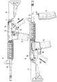
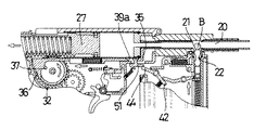
以下図示の実施形態を参照して本発明をより詳細に説明する。図1は、本発明に係る機械式通電停止装置10を搭載した電動銃の一例を示している。例示した電動銃は電動銃本体11に対して、着脱可能な外部装着式のマガジン12を備えており、マガジン12の内部には給弾経路13が設けられている(図2参照)。電動銃本体11は内部を銃腔14とする銃身部15を有し、その後部に電動銃の機関部16さらにその後部に銃床部17を有しており、機関部16の下部には引き金18が配置されている。なお、19はボルトストップと称する部品であるが、本発明においては後述するリセット操作のためのリセット部材として使用される。Bは弾丸であり、本実施形態ではBB弾と通称される直径6mmの球形弾丸を使用する。
Hereinafter, the present invention will be described in more detail with reference to the illustrated embodiments. FIG. 1 shows an example of an electric gun equipped with a mechanical
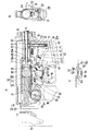
図2に詳細に示されているように、給弾経路13は銃腔後部の装弾部20の直後の給弾口21に通じており、給弾口21に至る給弾経路13には装弾部20へ弾丸を送るために付勢された玉押し部材22が移動可能に配置されている。玉押し部材22は一端部にてコイルばねより成る付勢部材24の付勢力を受け、他端部にて弾丸Bを給弾口21に向けて押すもので、最後の1発が給弾経路13の外まで完全に出る長さに設けられ、かつその先端部に弾丸Bとほぼ同型の球形頭部23を有している。
As shown in detail in FIG. 2, the
一方、銃腔14の後部の装弾部20の後方には通路25が通じており、この通路25には、後述するタペット部材35の先端部分35aが摺動可能に挿入されており、上記先端部分35aには、その後端において、ピストンシリンダー装置30のノズル28が摺動可能に挿入されている。通路25は、前記した給弾口21が形成されている部分であり、従って給弾口21はタペット部材35の先端部分35aによって開閉されることとなる。
On the other hand, a
ピストンシリンダー装置30は、電動銃本体11に取り付けられる固定側のシリンダー26と可動側のピストン27とから成り、シリンダー26の先端部に上述のノズル28が設けられていて、ピストン27の前進時に圧縮空気を前方へ噴射することができる。ピストン27はシリンダー内部にて気密に摺動可能に設けられており、かつ後方から前方へ強力なコイルばねより成る付勢手段29によって付勢されている。また、ピストン27は長手方向に沿ったラック31を有しており、このラック31はモーターによって駆動されるセクターギア32と噛み合い可能に配置されている。セクターギア32は、その周囲に、上記ラック31と噛み合ってピストン27を必要なストロークだけ後退させることができるギア部33と、ピストン27の拘束を解いて圧縮動作をさせるための無歯部34とを備えている。
The
上記のセクターギア32は、ギア部33との噛み合い開始後に一時的に給弾口21を開口させるタイミングでタペット部材35の後部係合部36と係合可能なピン37を軸周りに有している。タペット部材31は給弾口21を閉じる方向へコイルばねより成る付勢部材38の付勢力により移動して原位置へ復帰可能に設けられている。また、タペット部材35は前部に屈曲した係合部36aをそなえており、この係合部36aがタぺット部材摺動部の立ち上がり部35aと係合し、タペット部材35の前方への移動限界位置を規定する位置決め手段としての機能を果たしている。そしてタペット部材35は、本発明に係る機械式通電停止装置の一部としての役割を果たすために、後述するカットオフ部材50との係合手段39を具備している。この係合手段39はタペット部材35に開けられた開口窓39aの後縁である。
The
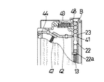
本発明に係る機械式通電停止装置10を構成するものとして、上記の玉押し部材22と一端部にて係合し、その移動と連動するフォロワー部材40が、給弾経路13の側方に配置されている。この例の場合、給弾経路13は着脱できるマガジン内部に設けられているので、フォロワー部材40もマガジン12に取り付けられることになる。フォロワー部材40は、給弾経路13に臨んで配置され、玉押し部材22の一部22aと係合する一端部41を有する第1リンク42と、第1リンク42との係合により連動して、それとは反対側のマガジン側面に配置される他端部43を有する第2リンク44とから成る。第1リンク42は一端部41が給弾経路13の側面に開けられた、スリット45に入り込むように設けられており、第2リンク44はマガジン他側面の開口部分46に露出しており、第1リンク42と、第1リンク42のどちらも揺動可能に取り付け部分に軸支されている。47は押しばねより成る付勢部材であり、第1リンク42の一端部41にて玉押し部材22を押し止めるとともに、第2リンク44の他端部43を受け部46に押し付けるように付勢する。
As a component of the mechanical
図3、図4に詳細に示したように、第1リンク42の一端部41は弾丸B及び玉押し部材22の球形頭部23とは係合しない。そこで、先端の弾丸Bに対する抜け止めのために給弾経路13に突き出して係合可能なストッパー48を押しばねより成る付勢部材49の付勢の下に配置する(図3参照)。なお、玉押し部材22の球形頭部23は、玉押し部材22の側の一部22aが一端部41と係合するまではストッパー48を通過して移動し、給弾経路13の外まで完全に出ることができる(図3参照)。
As shown in detail in FIGS. 3 and 4, the one
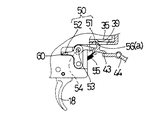
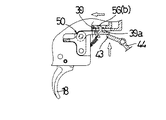
さらに本発明に係る機械式通電停止装置10を構成するものとして、タペット部材35の移動に伴い付勢部材38による移動力を借りてスイッチ56をオフにするために、カットオフ部材50が設けられている。図5の例におけるカットオフ部材50は、フォロワー部材40の第2リンク44の動きに伴い通電時の位置aから遮断時の位置bへ移動可能であり、かつ遮断時の位置bにてタペット部材35と係合する前部材51及び前部材51と連動し、その遮断時の位置bへの移動に伴い、後述するスイッチ57をオフにする後部材52とから成る。前部材51は、前部材51と後部材52を連結している軸53に、移動方向へやや長く形成された長孔54にて軸支されており、かつ第2リンク44の他端部43を押し下げる方向、或いはタペット部材35の係合手段39から離れる方向へ引きばねより成る付勢部材55によって付勢されている。また、前部材51は、上方後部に位置するタペット部材35の係合手段39との係合のために上後方へ屈曲した係合突部56を有しており、この係合突部56は通電時の位置aにてタペット部材35の下に位置し(図5参照)、タペット部材35が後方へ往復移動する過程で押し上げ力を受けることにより係合手段39と係合可能になる(図6及び図7参照)。
Further, as a component of the mechanical
上記スイッチ57は、図2A及びCに詳細に示されているように、一対のスイッチ端子58とそれらを切断するスイッチ片59とから構成されており、カットオフ部材50の後部材52に設けられている突部60にてスイッチ片59を押し動かすことにより、導通状態にあるスイッチ57を切断するように構成されている(図5ないし7参照)。スイッチ片59はスイッチ端子58に対して移動可能に設けられているとともに、スイッチ57を切断する方向へ付勢部材61によって付勢されている。
As shown in detail in FIGS. 2A and 2C, the
上記カットオフ部材50の前部材51を原位置へ戻すリセット操作のために、前述のリセット部材19が設けられている。このリセット部材19は電動銃本体11に支軸62により揺動可能かつ原位置方向へばねより成る付勢部材63によって付勢された状態に設けられており、その係合端部64は上記前部材51に設けられている係合端部65と係合可能に構成されている(図2B参照)。即ち、リセット部材19はカットオフ部材50の前部材51の上方移動により原位置から離され、図2Bに示された開いた状態になる。本発明に係る電動銃は電池を電源とし、グリップ66に配置されているモーターを動力源としており、引き金18の係合部67とスイッチ57の係合部68の係合によりスイッチ57が入ってモーターが回転し、減速歯車69を介してセクターギア32が駆動され、その1回転の間に、以下に説明するように弾丸発射に関わる全ての作動がなされる。
The
次に、このような構成を有する本発明に係る機械式通電停止装置10の作動について説明する。図8は弾丸Bを装填したマガジン12を電動銃本体11に装着し、発射準備を完了した状態を示しており、給弾経路13には1発の弾丸(最終弾)Bだけが残っている。この状態において引き金18を引くと、スイッチ片59が押されてスイッチ端子58と接触し、スイッチ57がオンになり、回路は通電状態になる(図9)。そしてセクターギア32の回転によりそのギア部33がピストン27のラック31と噛み合い、ピストン27が後退を開始し、次いで側面のピン37が後部係合部36と係合することによりタペット部材35が後退するときに、給弾口21が暫時開口するので、その間に最終弾Bは給弾口21を通過して装弾部後方の通路25に押し出される(図10)。
Next, the operation of the mechanical
最終弾Bが通路25に押し出されたため、玉押し部材22は最上の位置まで上昇しその
一部22aと一端部41にて係合している第1リンク42が揺動し、第2リンク44を揺動させてカットオフ部材50の前部材51を押し上げる。この押し上げにより、最終弾Bが装填されつつあり、マガジン12に弾丸Bの無くなったことがカットオフ部材50に伝えられたことになる。この、第2リンク44によってカットオフ部材50の前部材51が押し上げられている段階において、上記タペット部材35の後退復帰移動が行われることに伴い、タペット部材35の開口窓39aが、カットオフ部材50の前部材51に設けられている係合突部56の上部を通過するので、係合突部56が開口窓39aに入り込み、さらに後縁の係合手段39と係合することになる(図11)。また、ピストン27が限界位置まで後退した後、前進を開始するまでの間に、タペット部材35は前進動作を行って原位置へ戻り、その前進に伴い先端部分35aによって最終弾Bを装弾部20へと押し動かし、弾丸Bが装弾部20に装填される。
Since the last bullet B is pushed out into the
図11の段階に至って係合突部56が係合手段39と係合することにより、タペット部材35に作用する付勢力により上記カットオフ部材50を動作させるので、スイッチ端子58とスイッチ片59が離間してスイッチ57はオフになり、モーターは停止する。一方ピストン27は後退限界位置から付勢部材29の弾発力を受けて前進に移り、圧縮空気を生成し、それがノズル28から弾丸Bに噴射されることにより、弾丸Bを銃口から発射させることになる(図12)。弾丸Bが発射されても、カットオフ部材50の前部材51は係合突部56にて係合手段39と係合した状態を保っている。そこで、リセット部材19を図2Bにおいて反時計方向へ操作し、上記の前部材51を押し下げて原位置(通電側位置、図5参照)に戻すことにより、発射可能な状態にする。そしてマガジン12と取り外し弾丸Bを詰めて電動銃本体11に装着し直すことにより、再び弾丸を発射できる状態にすることができるが、このモデルとなった米軍制式採用銃M4を始めとする実銃では、マガジン交換の後でリセット操作をする手順を取るので、本発明の電動銃においても実銃同様にマガジン交換の後にリセット部材19を操作することができる。
When the
このように、本発明は電動銃本体内における弾丸Bの有無をフォロワー部材40により機械的に検出し、かつまたタペット部材35の付勢力を、スイッチ57を切る動力に利用して作動を電気的でなく機械的に停止させることができる。上記の構成及び作用は、既に述べたように、マガジンを有さず従ってマガジンを横断するようなリンク部材を使用しない電動銃本体にも適用できることは勿論である。
As described above, the present invention mechanically detects the presence or absence of the bullet B in the electric gun body by the
10 機械式通電停止装置
11 電動銃本体
12 マガジン
13 給弾経路
14 銃腔
15 銃身部
16 機関部
17 銃床部
18 引き金
19 リセット部材
20 装弾部
21 給弾口
22 玉押し部材
23 球形頭部
24、29、38、49、53、61、63 付勢部材
25 通路
26 シリンダー
27 ピストン
28 ノズル
30 ピストンシリンダー装置
31 ラック
32 セクターギア
33 ギア部
34 無歯部
35 タぺット部材
36 後部係合部
37 ピン
39 係合手段
40 フォロワー部材
41 一端部
42 第1リンク
43 他端部
44 第2リンク
45 スリット
46 受け部
48 ストッパー
50 カットオフ部材
51 前部材
52 後部材
54 軸
55 長孔
56 係合突部
57 スイッチ
58 スイッチ端子
59 スイッチ片
60 突部
62 支軸
64、65 係合端部
66 グリップ66
67、68 係合部
69 減速歯車
DESCRIPTION OF
25
67, 68
Claims (3)
給弾経路に移動可能に配置されかつ装弾部へ弾丸を送るために付勢された玉押し部材と、
玉押し部材側の一部と一端部にて係合しその移動と連動するフォロワー部材と、
フォロワー部材の動きに伴い通電時の位置から遮断時の位置へ移動可能でありかつ遮断時の位置への移動の過程においてタペット部材と係合し、タペット部材の移動に伴いスイッチをオフにするカットオフ部材と、
駆動部のピストンの移動に伴い後退して装弾部に通じる給弾経路の給弾口を開く先端部分を有しかつその給弾口を閉じる方向への付勢力により上記カットオフ部材を動作させる上記のタペット部材と、
カットオフ部材との係合により移動して接点が開き、リセット操作により接点を閉じる上記のスイッチとを備えた
電動銃における機械式通電停止装置。 When there is no bullet in the bullet feed path leading to the bullet part at the rear of the gun cavity, the device for shutting off the energization by interrupting the circuit of the drive unit that fires the bullet,
A tapping member that is movably disposed in the bullet feed path and biased to send a bullet to the loading section;
A follower member that engages with a part of the claw member and one end and interlocks with the movement,
A cut that can move from the energized position to the shut-off position with the movement of the follower member, and engages with the tappet member in the process of moving to the shut-off position, and turns off the switch as the tappet member moves. An off member;
The cut-off member is operated by a biasing force in a direction to close the bullet feed port, having a tip portion that opens the bullet feed port of the bullet feed path that retreats with the movement of the piston of the drive unit and leads to the bullet loading unit. Tappet members of
A mechanical energization stop device for an electric gun comprising the above switch that moves by engagement with a cut-off member to open a contact and closes the contact by a reset operation.
Priority Applications (1)
| Application Number | Priority Date | Filing Date | Title |
|---|---|---|---|
| JP2008190187A JP4965526B2 (en) | 2008-07-23 | 2008-07-23 | Mechanical energization stop device for electric gun |
Applications Claiming Priority (1)
| Application Number | Priority Date | Filing Date | Title |
|---|---|---|---|
| JP2008190187A JP4965526B2 (en) | 2008-07-23 | 2008-07-23 | Mechanical energization stop device for electric gun |
Publications (3)
| Publication Number | Publication Date |
|---|---|
| JP2010025501A true JP2010025501A (en) | 2010-02-04 |
| JP2010025501A5 JP2010025501A5 (en) | 2012-03-08 |
| JP4965526B2 JP4965526B2 (en) | 2012-07-04 |
Family
ID=41731514
Family Applications (1)
| Application Number | Title | Priority Date | Filing Date |
|---|---|---|---|
| JP2008190187A Active JP4965526B2 (en) | 2008-07-23 | 2008-07-23 | Mechanical energization stop device for electric gun |
Country Status (1)
| Country | Link |
|---|---|
| JP (1) | JP4965526B2 (en) |
Cited By (5)
| Publication number | Priority date | Publication date | Assignee | Title |
|---|---|---|---|---|
| KR101485402B1 (en) | 2013-05-02 | 2015-01-26 | 김동현 | The electric gun, having a stop-firing function |
| WO2016151764A1 (en) * | 2015-03-24 | 2016-09-29 | 株式会社東京マルイ | Cut-off device of electric mechanism in imitation gun |
| KR20180082996A (en) | 2015-10-16 | 2018-07-19 | 가부시키가이샤 도쿄 마루이 | Bolt stop shock absorber in gun |
| WO2019058525A1 (en) | 2017-09-22 | 2019-03-28 | 株式会社東京マルイ | Device for inhibiting firing of shells in an electric gun |
| WO2019058526A1 (en) | 2017-09-22 | 2019-03-28 | 株式会社東京マルイ | Device for stopping function for inhibiting firing of shells |
Families Citing this family (1)
| Publication number | Priority date | Publication date | Assignee | Title |
|---|---|---|---|---|
| JP7387144B2 (en) | 2019-09-24 | 2023-11-28 | 株式会社東京マルイ | toy gun |
Citations (10)
| Publication number | Priority date | Publication date | Assignee | Title |
|---|---|---|---|---|
| JPH03221793A (en) * | 1990-01-25 | 1991-09-30 | Tokyo Marui:Kk | Automatic air gun |
| JPH06235597A (en) * | 1993-02-09 | 1994-08-23 | Tokyo Marui:Kk | Electric air gun |
| JP2002168594A (en) * | 2000-12-01 | 2002-06-14 | K S C:Kk | Motor-operated toy gun |
| US6560911B2 (en) * | 1999-10-06 | 2003-05-13 | Ronnie L. Sharp | Adjustable gun stock |
| US20030098019A1 (en) * | 2001-11-29 | 2003-05-29 | Shih-Che Hu | Motorized toy gun |
| WO2005066576A1 (en) * | 2003-12-26 | 2005-07-21 | Koichi Tsurumoto | Air gun and firing stop control method |
| US7100592B1 (en) * | 2005-06-24 | 2006-09-05 | Unicorn Hobby Corp. | Toy gun having dual actuating manners |
| JP2006234191A (en) * | 2005-02-22 | 2006-09-07 | Katsumi Nagayoshi | Magazine with continuous bullet supply mechanism and toy gun with continuous shooting function |
| JP2006300464A (en) * | 2005-04-22 | 2006-11-02 | Tokyo Marui:Kk | Electric gun |
| JP2008008525A (en) * | 2006-06-28 | 2008-01-17 | Howa Mach Ltd | Expandable stock for gun |
-
2008
- 2008-07-23 JP JP2008190187A patent/JP4965526B2/en active Active
Patent Citations (11)
| Publication number | Priority date | Publication date | Assignee | Title |
|---|---|---|---|---|
| JPH03221793A (en) * | 1990-01-25 | 1991-09-30 | Tokyo Marui:Kk | Automatic air gun |
| JPH06235597A (en) * | 1993-02-09 | 1994-08-23 | Tokyo Marui:Kk | Electric air gun |
| US6560911B2 (en) * | 1999-10-06 | 2003-05-13 | Ronnie L. Sharp | Adjustable gun stock |
| JP2002168594A (en) * | 2000-12-01 | 2002-06-14 | K S C:Kk | Motor-operated toy gun |
| US20030098019A1 (en) * | 2001-11-29 | 2003-05-29 | Shih-Che Hu | Motorized toy gun |
| CN1425892A (en) * | 2001-11-29 | 2003-06-25 | 胡世泽 | Electric toy gun |
| WO2005066576A1 (en) * | 2003-12-26 | 2005-07-21 | Koichi Tsurumoto | Air gun and firing stop control method |
| JP2006234191A (en) * | 2005-02-22 | 2006-09-07 | Katsumi Nagayoshi | Magazine with continuous bullet supply mechanism and toy gun with continuous shooting function |
| JP2006300464A (en) * | 2005-04-22 | 2006-11-02 | Tokyo Marui:Kk | Electric gun |
| US7100592B1 (en) * | 2005-06-24 | 2006-09-05 | Unicorn Hobby Corp. | Toy gun having dual actuating manners |
| JP2008008525A (en) * | 2006-06-28 | 2008-01-17 | Howa Mach Ltd | Expandable stock for gun |
Cited By (12)
| Publication number | Priority date | Publication date | Assignee | Title |
|---|---|---|---|---|
| KR101485402B1 (en) | 2013-05-02 | 2015-01-26 | 김동현 | The electric gun, having a stop-firing function |
| WO2016151764A1 (en) * | 2015-03-24 | 2016-09-29 | 株式会社東京マルイ | Cut-off device of electric mechanism in imitation gun |
| JPWO2016151764A1 (en) * | 2015-03-24 | 2018-01-11 | 株式会社東京マルイ | Cut-off device for electric mechanism in simulated gun |
| US10401120B2 (en) | 2015-03-24 | 2019-09-03 | Tokyo Marui Co., Ltd. | Cut-off device for electric mechanism in simulation gun |
| KR20180082996A (en) | 2015-10-16 | 2018-07-19 | 가부시키가이샤 도쿄 마루이 | Bolt stop shock absorber in gun |
| US10330407B2 (en) | 2015-10-16 | 2019-06-25 | Tokyo Marui Co, Ltd. | Bolt stop buffer device in gun |
| WO2019058525A1 (en) | 2017-09-22 | 2019-03-28 | 株式会社東京マルイ | Device for inhibiting firing of shells in an electric gun |
| WO2019058526A1 (en) | 2017-09-22 | 2019-03-28 | 株式会社東京マルイ | Device for stopping function for inhibiting firing of shells |
| EP3686543A4 (en) * | 2017-09-22 | 2021-04-14 | TOKYO MARUI Co., Ltd. | Device for stopping function for inhibiting firing of shells |
| EP3686544A4 (en) * | 2017-09-22 | 2021-06-23 | TOKYO MARUI Co., Ltd. | Device for inhibiting firing of shells in an electric gun |
| TWI759527B (en) * | 2017-09-22 | 2022-04-01 | 日商東京丸井股份有限公司 | Missing shot prevention function stop device, magazine part and electric gun |
| TWI801406B (en) * | 2017-09-22 | 2023-05-11 | 日商東京丸井股份有限公司 | Empty gun prevention device in electric gun |
Also Published As
| Publication number | Publication date |
|---|---|
| JP4965526B2 (en) | 2012-07-04 |
Similar Documents
| Publication | Publication Date | Title |
|---|---|---|
| JP4965526B2 (en) | Mechanical energization stop device for electric gun | |
| US8091542B2 (en) | Electric toy gun with a power break control mechanism | |
| JP4700123B2 (en) | Electric air gun | |
| KR101282903B1 (en) | An air-gun for airsoft game | |
| US8146577B2 (en) | Electric toy gun with an improved power break control mechanism | |
| US7694448B2 (en) | Recoil shock device in toy gun | |
| JP4719807B2 (en) | Safety device for simulated gun | |
| JP2015021713A (en) | Toy gun | |
| EP2065668B1 (en) | Air gun | |
| EP2390614A1 (en) | Electric toy gun with an improved power break control mechanism | |
| JPWO2019058526A1 (en) | Empty shot prevention function stop device | |
| JP2006300464A (en) | Electric gun | |
| JP2006300462A (en) | Electric gun | |
| JP2010025501A5 (en) | ||
| JP4241314B2 (en) | Launch mode switching device for electric air gun | |
| CN215676659U (en) | Toy gun wave box | |
| JP4719808B2 (en) | Side feed device for simulated gun | |
| CN110081775B (en) | Automatic bullet supply device of semi-automatic air gun and semi-automatic air gun | |
| CN210180278U (en) | Automatic bullet supply device of semi-automatic air gun and semi-automatic air gun | |
| JP4745011B2 (en) | Device for controlling the number of firings in an electric gun | |
| JPH08303991A (en) | Electrical discharge actuator for toy handgun capable of stabilized discharge actuation | |
| JP7387144B2 (en) | toy gun | |
| JP2006300463A (en) | Electric gun | |
| JP7360693B2 (en) | electric toy gun | |
| WO2020253095A1 (en) | Automated bullet loading device for semi-automatic air gun, and semi-automatic air gun |
Legal Events
| Date | Code | Title | Description |
|---|---|---|---|
| A621 | Written request for application examination |
Free format text: JAPANESE INTERMEDIATE CODE: A621 Effective date: 20100401 |
|
| A521 | Request for written amendment filed |
Free format text: JAPANESE INTERMEDIATE CODE: A523 Effective date: 20120125 |
|
| A871 | Explanation of circumstances concerning accelerated examination |
Free format text: JAPANESE INTERMEDIATE CODE: A871 Effective date: 20120125 |
|
| TRDD | Decision of grant or rejection written | ||
| A975 | Report on accelerated examination |
Free format text: JAPANESE INTERMEDIATE CODE: A971005 Effective date: 20120222 |
|
| A977 | Report on retrieval |
Free format text: JAPANESE INTERMEDIATE CODE: A971007 Effective date: 20120229 |
|
| A01 | Written decision to grant a patent or to grant a registration (utility model) |
Free format text: JAPANESE INTERMEDIATE CODE: A01 Effective date: 20120306 |
|
| A01 | Written decision to grant a patent or to grant a registration (utility model) |
Free format text: JAPANESE INTERMEDIATE CODE: A01 |
|
| A61 | First payment of annual fees (during grant procedure) |
Free format text: JAPANESE INTERMEDIATE CODE: A61 Effective date: 20120329 |
|
| R150 | Certificate of patent or registration of utility model |
Ref document number: 4965526 Country of ref document: JP Free format text: JAPANESE INTERMEDIATE CODE: R150 Free format text: JAPANESE INTERMEDIATE CODE: R150 |
|
| FPAY | Renewal fee payment (event date is renewal date of database) |
Free format text: PAYMENT UNTIL: 20150406 Year of fee payment: 3 |
|
| R250 | Receipt of annual fees |
Free format text: JAPANESE INTERMEDIATE CODE: R250 |
|
| R250 | Receipt of annual fees |
Free format text: JAPANESE INTERMEDIATE CODE: R250 |
|
| R250 | Receipt of annual fees |
Free format text: JAPANESE INTERMEDIATE CODE: R250 |
|
| R250 | Receipt of annual fees |
Free format text: JAPANESE INTERMEDIATE CODE: R250 |
|
| R250 | Receipt of annual fees |
Free format text: JAPANESE INTERMEDIATE CODE: R250 |
|
| R250 | Receipt of annual fees |
Free format text: JAPANESE INTERMEDIATE CODE: R250 |
|
| R250 | Receipt of annual fees |
Free format text: JAPANESE INTERMEDIATE CODE: R250 |
|
| R250 | Receipt of annual fees |
Free format text: JAPANESE INTERMEDIATE CODE: R250 |
|
| R250 | Receipt of annual fees |
Free format text: JAPANESE INTERMEDIATE CODE: R250 |
|
| R250 | Receipt of annual fees |
Free format text: JAPANESE INTERMEDIATE CODE: R250 |