JP2010025076A - Flow passage structure - Google Patents
Flow passage structure Download PDFInfo
- Publication number
- JP2010025076A JP2010025076A JP2008190595A JP2008190595A JP2010025076A JP 2010025076 A JP2010025076 A JP 2010025076A JP 2008190595 A JP2008190595 A JP 2008190595A JP 2008190595 A JP2008190595 A JP 2008190595A JP 2010025076 A JP2010025076 A JP 2010025076A
- Authority
- JP
- Japan
- Prior art keywords
- flow path
- sound absorbing
- jet
- cross
- flow passage
- Prior art date
- Legal status (The legal status is an assumption and is not a legal conclusion. Google has not performed a legal analysis and makes no representation as to the accuracy of the status listed.)
- Granted
Links
Images


Landscapes
- Exhaust Silencers (AREA)
Abstract
Description
本発明は、ジェットを噴出するエンジンを収容する収容体に設けられる流路構造体に関する。 The present invention relates to a flow path structure provided in a housing that houses an engine that ejects a jet.
ジェットを噴出するエンジン1(例えばジェットエンジン)において、図5に示すように、収容体3の内部にエンジン1を収容させる場合がある。この収容体3室内で、例えばエンジン1を作動させエンジン1からジェット排ガス(高速の燃焼ガス)を排出させる。そのための流路11を有する流路構造体13が収容体3に設けられる。具体的には、流路11の一端が、流路11の収容体3の内部にてジェット排ガスを受け入れるように開口し、流路11の他端は前記収容体3の外部に開口し、これにより、ジェット排ガスは、流路11を通って収容体3の外部に放出される。
In an engine 1 (for example, a jet engine) that ejects a jet, the
収容体3内で発生するジェット排ガスの排出には、次に2つの性能が必要である。
(1)エジェクタ性能
エジェクタ性能とは、動力を使わずに、ジェット排ガスが、収容体3内の空気(以下、室内空気ともいう)に包み込まれるように室内空気を連行して、圧力の低い収容体3内から圧力の高い収容体3外部へ放出される性能である。このエジェクタ性能が良好でない場合、ジェット排ガスにおける外周部分の排ガスが、収容体3内に漏れて排ガス有毒成分が収容体3内にこもるだけでなく、収容体3内の温度が上昇しエンジンの運転もできなくなる。
(2)消音性能
この消音性能が良好でない場合、当然ながらやかましい。
In order to discharge the jet exhaust gas generated in the
(1) Ejector performance Ejector performance is the accommodation of low pressure by entraining indoor air so that jet exhaust gas is wrapped in the air in the housing 3 (hereinafter also referred to as room air) without using power. This is the performance released from the inside of the
(2) Noise reduction performance If this noise reduction performance is not good, it is naturally noisy.
(従来技術1)
消音性能を確保するためには、吸音材とジェット排ガスとの接触面積を大きくする必要がある。そこで、流路内に、スプリッタ型吸音材や円筒型吸音材を設けている。図6は、スプリッタ型吸音材15を設けた場合を示し、図7は、円筒型吸音材17を設けた場合を示している。図6と図7において、(B)は(A)のB−B線矢視図である。
(従来技術2)
また、流路壁のみを吸音材仕上げとすることも行われている。なお、この場合、流路壁の外側圧力を高くして吸音材表面とジェット排ガスとの抵抗を低減することができる(特許文献1を参照)。
(従来技術3)
収容体3がハッシュハウスやエンジンテストセルなどである場合には、図8に示すように、流路において、まずエジェクタ部19を設け、これの下流側で、エジェクタ部19から曲がった箇所において、スプリッタ型吸音材15を配置したスプリッタ部21を設けている。この構成では、エジェクタ部19で、ジェット動圧を静圧上昇に変換し、この後、スプリッタ部21で消音を行う。なお、図8(B)は図8(A)のB−B線矢視図である。
(従来技術4)
流路の距離をとれない場合には、エジェクタ効果を利用することをあきらめて、換気ファンを設けていた。この場合、換気ファンで、ジェット排ガスを室内空気ごと、外部に引き出す。
In order to ensure the sound deadening performance, it is necessary to increase the contact area between the sound absorbing material and the jet exhaust gas. Therefore, a splitter type sound absorbing material or a cylindrical sound absorbing material is provided in the flow path. 6 shows the case where the splitter type
(Prior art 2)
In addition, only the flow path wall is finished with a sound absorbing material. In this case, the resistance between the sound absorbing material surface and the jet exhaust gas can be reduced by increasing the outer pressure of the flow path wall (see Patent Document 1).
(Prior art 3)
When the
(Prior art 4)
When the distance of the flow path could not be taken, we gave up using the ejector effect and provided a ventilation fan. In this case, the jet exhaust gas is drawn out together with the indoor air by a ventilation fan.
従来技術1では、吸音材15、17とジェット排ガスとの接触面積が広いので、短い流路構造で十分に吸音できる。しかし、従来技術1では、スプリッタ型吸音材15または円筒型吸音材17が、ジェット排ガスを分割するので、ジェット排ガスと周囲空気との乱流混合が十分でない。このため、エジェクタ効果が働かず、ジェット排ガスは、収容体3外部へ室内空気を連行できない。
一方、従来技術2では、エジェクタ効果は十分に働くが、吸音材とジェット排ガスとの接触面積が小さくなるため、長い流路構造が必要となる。
また、従来技術3では、エジェクタ部の下流にスプリッタ部を設けるため、非常に長い流路構造となる。
従来技術4では、換気ファンを駆動する動力が必要となるだけでなく、換気ファンの耐熱性を考慮して、過剰な空気を収容体内に引き込んでガス平均温度を十分に下げる必要がある。
In the
On the other hand, in the prior art 2, the ejector effect works sufficiently, but since the contact area between the sound absorbing material and the jet exhaust gas becomes small, a long flow path structure is required.
Moreover, in the
In the prior art 4, not only power for driving the ventilation fan is required, but also considering the heat resistance of the ventilation fan, it is necessary to sufficiently reduce the average gas temperature by drawing excess air into the housing.
そこで、本発明の目的は、高いエジェクタ性能を得ることができるとともに、短い流路構造で十分な吸音性能を得ることができる流路構造体を提供することにある。 Therefore, an object of the present invention is to provide a flow path structure that can obtain high ejector performance and can obtain sufficient sound absorption performance with a short flow path structure.
上記目的を達成するため、本発明によると、ジェットを収容体内部から外部に放出する流路構造体であって、
ジェットを通す流路が形成されており、
該流路の一端は前記収容体の内部にて前記ジェット及びエジェクタによる周囲空気を受け入れるように開口し、前記流路の他端は前記収容体の外部に開口し、
前記流路の断面中心に対し放射状に延びるとともに、前記断面中心を回る周方向に間隔を置いて配置される複数の吸音材を備える、ことを特徴とする流路構造体が提供される。
In order to achieve the above object, according to the present invention, a flow path structure that discharges a jet from the inside of a container to the outside,
A flow path through which the jet passes is formed,
One end of the flow path is opened to receive the ambient air from the jet and ejector inside the container, and the other end of the flow path is opened to the outside of the container.
There is provided a flow path structure characterized by comprising a plurality of sound absorbing materials that extend radially with respect to the cross-sectional center of the flow path and are arranged at intervals in the circumferential direction around the cross-sectional center.
上述した本発明の流路構造体では、複数の吸音材が、前記流路の断面中心に対し放射状に延びるので、この放射方向に収容体内の空気とジェット(例えば、ジェット排ガス)とを十分に混合することができ、これにより、エジェクタとしての圧力上昇が可能になる。従って、高いエジェクタ性能が得られ、圧力の低い収容体内の空気が、ジェットを包むように、ジェットに連行されて収容体外部に放出されるようになる。
また、複数の吸音材が、前記断面中心を回る周方向に間隔を置いて配置されるので、吸音材とジェットとの接触面積を、流路方向の単位距離あたり大きくできる。従って、短い流路構造で十分な吸音性能を得ることができる。
In the above-described flow channel structure of the present invention, since the plurality of sound absorbing materials extend radially with respect to the cross-sectional center of the flow channel, air and a jet (for example, jet exhaust gas) in the container are sufficiently supplied in this radial direction. Mixing can be performed, and this makes it possible to increase the pressure as an ejector. Therefore, high ejector performance is obtained, and the air in the container having a low pressure is entrained by the jet and discharged to the outside of the container so as to wrap the jet.
Further, since the plurality of sound absorbing materials are arranged at intervals in the circumferential direction around the center of the cross section, the contact area between the sound absorbing material and the jet can be increased per unit distance in the flow path direction. Therefore, sufficient sound absorption performance can be obtained with a short flow path structure.
本発明の好ましい実施形態によると、前記各吸音材は、前記断面中心から所定距離だけ隔てた位置から、前記断面中心から離れる方向に延びている。 According to a preferred embodiment of the present invention, each of the sound absorbing materials extends in a direction away from the cross-sectional center from a position separated from the cross-sectional center by a predetermined distance.
このように、前記各吸音材は、前記断面中心から所定距離だけ隔てた位置から、前記断面中心から離れる方向に延びているので、前記流路の断面中心部には、吸音材が位置しないようになっている。これにより、ジェットの流れ抵抗を最小限にすることができる。即ち、断面中心部では、ジェットの流速が最も大きくなるが、この部分は、吸音材が存在しない完全な空洞となるので、ジェットの流れ抵抗を最小限にすることができる。 Thus, each sound absorbing material extends in a direction away from the center of the cross section from a position separated by a predetermined distance from the center of the cross section, so that the sound absorbing material is not located at the center of the cross section of the flow path. It has become. Thereby, the flow resistance of the jet can be minimized. That is, the flow velocity of the jet is the largest at the center of the cross section, but this portion is a complete cavity where no sound absorbing material is present, so the flow resistance of the jet can be minimized.
本発明の好ましい実施形態によると、前記周方向に配置される前記吸音材の数は、前記流路の内周側部分よりも外周側部分のほうが多くなっている。 According to a preferred embodiment of the present invention, the number of the sound absorbing materials arranged in the circumferential direction is greater in the outer peripheral side portion than in the inner peripheral side portion of the flow path.
このように、前記周方向に配置される前記吸音材の数は、前記流路の内周側部分よりも外周側部分のほうが多くなっているので、内周側部分と外周側部分との間で、周方向に関する吸音材同士の間隔を、均一に近づけることができる。これにより、周方向に関する吸音材同士の間隔の均一化を図ることができる。 Thus, since the number of the sound absorbing materials arranged in the circumferential direction is larger in the outer peripheral side portion than in the inner peripheral side portion of the flow path, the interval between the inner peripheral side portion and the outer peripheral side portion is larger. Thus, the intervals between the sound absorbing materials in the circumferential direction can be made closer to each other. Thereby, the space | interval of the sound absorption materials regarding the circumferential direction can be equalize | homogenized.
上述した本発明によると、高いエジェクタ性能を得ることができるとともに、短い流路構造で十分な吸音性能を得ることができる。 According to the present invention described above, high ejector performance can be obtained, and sufficient sound absorption performance can be obtained with a short flow path structure.
本発明を実施するための最良の実施形態を図面に基づいて説明する。なお、各図において共通する部分には同一の符号を付し、重複した説明を省略する。 The best mode for carrying out the present invention will be described with reference to the drawings. In addition, the same code | symbol is attached | subjected to the common part in each figure, and the overlapping description is abbreviate | omitted.
[第1実施形態]
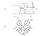
図1は、本発明の第1実施形態による流路構造体10を示す図である。図1(B)は、図1(A)のB−B線矢視図である。流路構造体10は、ジェットを噴出するエンジン1(例えば、ジェットエンジン)を内部に収容する収容体3に設けられる。この流路構造体10には、エンジン1から噴出されるジェット(例えば、ジェット排ガス)を通す流路5が形成されている。図1に示すように、該流路5の一端は前記収容体3の内部に開口し、前記流路5の他端は前記収容体3の外部に開口し、流路5一端の開口は、エンジン1からのジェット排ガス及びエジェクタによる周囲空気を受け入れるように配置されている。これにより、前記ジェット排ガスは、前記流路5を通って前記収容体3の外部に放出されるようになっている。収容体3は、例えば、ホバークラフトなどエンジン1から噴出されるジェットで推進力または方向転換用推力を得ることで移動する移動装置に設けられているものであってよい。
[First Embodiment]
FIG. 1 is a view showing a
本実施形態によると、流路構造体10は、複数の吸音材7を備える。各吸音材7の形状は、板状であってよい。複数の吸音材7は、前記流路5の断面中心Cに対し放射状に延びる。図1の例では、各吸音材7は、放射状に流路5の内壁5aまで延びており、この内壁5aに結合・支持されている。
また、前記断面中心Cを回る周方向に間隔を置いて、複数の吸音材7が配置される。好ましくは、複数の吸音材7は等間隔で周方向に配置される。
According to this embodiment, the
A plurality of sound absorbing materials 7 are arranged at intervals in the circumferential direction around the center C of the cross section. Preferably, the plurality of sound absorbing materials 7 are arranged in the circumferential direction at equal intervals.
本発明によると、複数の吸音材7は、断面中心Cから流路5の内壁5aまで延びていてもよい。この場合、複数の吸音材7同士は断面中心Cにおいて結合されていてよい。
しかし、流路5の断面中心部では、ジェット排ガスの流速が最も高くなるので、この部分の流れ抵抗を低減するように、流路5中心部を完全な空洞とするのが好ましい。そのために、図1(B)の例では、前記各吸音材7は、前記断面中心Cから所定距離だけ隔てた位置から、前記断面中心Cから離れる方向に流路5の内壁5aまで延びている。
According to the present invention, the plurality of sound absorbing materials 7 may extend from the cross-sectional center C to the
However, since the flow velocity of the jet exhaust gas is highest in the central portion of the cross section of the
上述した第1実施形態による流路構造体10では、複数の吸音材7が、前記流路5の断面中心Cに対し放射状に延びるので、この放射方向に収容体3内の空気とジェット排ガスとを十分に混合することができ、これにより、エジェクタとしての圧力上昇が可能になる。従って、高いエジェクタ性能が得られ、圧力の低い収容体3内の周囲空気が、ジェット排ガスを包むように、ジェット排ガスに連行されて収容体3外部に放出されるようになる。より詳しく説明する。エジェクタ効果は、ジェット排ガスの運動量が、周囲空気(2次空気)に拡散することにより静圧を上昇させ(即ち、2次空気吸引負圧を発生させ)、ジェット排ガスを周囲空気とともに排出させる効果である。このためには、ジェット排ガスと周囲空気が十分に一体となる混合が必要である。図6、図7に示す従来のように吸音材15、17を配置すると、前記放射方向の混合が妨げられるが、図1に示す本実施形態のように吸音材7を配置することで、混合が妨げられることが防止され、前記放射方向に十分な混合がなされる。
さらに、本実施形態では、複数の吸音材7が、前記断面中心Cを回る周方向に間隔を置いて配置されるので、吸音材7とジェット排ガスとの接触面積を、流路方向の単位距離あたり大きくできる。従って、短い流路構造で十分な吸音性能を得ることができる。
In the
Further, in the present embodiment, since the plurality of sound absorbing materials 7 are arranged at intervals in the circumferential direction around the cross-sectional center C, the contact area between the sound absorbing material 7 and the jet exhaust gas is determined as a unit distance in the flow path direction. Can be bigger. Therefore, sufficient sound absorption performance can be obtained with a short flow path structure.
また、前記各吸音材7は、前記断面中心Cから所定距離だけ隔てた位置から、前記断面中心Cから離れる方向に延びているので、前記流路5の断面中心部には、吸音材7が位置しないようになっている。これにより、ジェット排ガスの流れ抵抗を最小限にすることができる。即ち、断面中心部では、ジェット排ガスの流速が最も大きくなるが、この部分は、吸音材7が存在しない完全な空洞となるので、ジェット排ガスの流れ抵抗を最小限にすることができる。
Further, since each of the sound absorbing materials 7 extends in a direction away from the cross sectional center C from a position separated from the cross sectional center C by a predetermined distance, the sound absorbing material 7 is disposed at the central portion of the cross section of the
なお、図1の例では、各吸音材7は、流路5の内壁5aに支持されているが、図2のように補強してもよい。図2(B)は、図2(A)のB−B線矢視図である。図2に示すように、リング状の補強部材9が設けられる。この補強部材9には、各吸音材7の内端が結合されている。これにより、流路5の内壁5aと補強部材9とで、各吸音材7が両持ち支持される。また、流路方向(図2(A)の左右方向)における補強部材9の厚みは、流路方向における各吸音材7の長さよりも大幅に小さいので、ジェット排ガスと周囲空気と混合を妨げない。
In the example of FIG. 1, each sound absorbing material 7 is supported by the
また、各吸音材7は、流路方向に流路5の一端から他端まで延びていてよい。
Each sound absorbing material 7 may extend from one end of the
[第2実施形態]
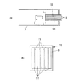
次に本発明の第2実施形態による流路構造体10について説明する。第2実施形態では、以下で説明する構成以外は、第1実施形態と同じであってよい。図3は、本発明の第2実施形態による流路構造体10を示す。図3(B)は、図3(A)のB−B線矢視図である。図3では、符号7の代わりに符号7a,7bを用いて吸音材を示している。
[Second Embodiment]
Next, the
第2実施形態によると、図3(B)に示すように、前記周方向に配置される前記吸音材7a,7bの数は、前記流路5の内周側部分よりも外周側部分のほうが多くなっている。なお、図3(B)において、内周側部分は破線の内側であり、外周側部分は破線と流路5の内壁5aとの間の部分である。このように、前記周方向において存在する前記吸音材7a,7bの数は、前記流路5の内周側部分よりも外周側部分のほうが多くなっているので、内周側部分と外周側部分との間で、周方向に関する吸音材7a,7b同士の間隔を、均一に近づけることができる。これにより、周方向に関する吸音材7a,7b同士の間隔の均一化を図ることができる。
言い換えると、第2実施形態では、流路5の内壁5aから断面中心Cに向かう放射方向の寸法が異なる2種類の吸音材7a,7bを設けることで、周方向に関する吸音材7a,7b同士の間隔の均一化を図っている。なお、第2実施形態によると、前記寸法が異なる吸音材は、2種類に限定されず、3種類以上であってもよい。これにより、周方向に関する吸音材同士の間隔の均一度をさらに高めることができる。
第2実施形態の他の構成と効果は、第1実施形態と同じである。
According to the second embodiment, as shown in FIG. 3B, the number of the
In other words, in the second embodiment, by providing two types of
Other configurations and effects of the second embodiment are the same as those of the first embodiment.
なお、図3の例では、各吸音材7a,7bは、流路5の内壁5aに結合・支持されているが、図4のように補強してもよい。図4(B)は、図4(A)のB−B線矢視図である。図4に示すように、リング状の補強部材9a、9bが設けられる。補強部材9aには、各吸音材7aの内端と各吸音材7bの中間部とが結合されている。また、補強部材9bには、各吸音材7bの内端が結合されている。また、流路方向(図4(A)の左右方向)における補強部材9a,9bの厚みは、流路方向における各吸音材7の長さよりも大幅に小さいので、ジェット排ガスと周囲空気と混合を妨げない。
In the example of FIG. 3, each of the
本発明は上述した実施の形態に限定されず、本発明の要旨を逸脱しない範囲で種々変更を加え得ることは勿論である。 The present invention is not limited to the above-described embodiment, and various changes can be made without departing from the scope of the present invention.
例えば、上述の実施形態では流路5の断面形状は円形であったが、本発明によると、流路5の断面形状は矩形などの他の形状であってもよい。
For example, although the cross-sectional shape of the
1 エンジン、3 収容体、5 流路、5a 流路の内壁、7,7a,7b 吸音材、9 補強部材、10 流路構造体、11 流路、13 流路構造体、15 スプリッタ型吸音材、17 円筒型吸音材、
DESCRIPTION OF
Claims (3)
ジェットを通す流路が形成されており、
該流路の一端は前記収容体の内部にて前記ジェット及びエジェクタによる周囲空気を受け入れるように開口し、前記流路の他端は前記収容体の外部に開口し、
前記流路の断面中心に対し放射状に延びるとともに、前記断面中心を回る周方向に間隔を置いて配置される複数の吸音材を備える、ことを特徴とする流路構造体。 A flow path structure for discharging a jet from the inside of the container to the outside,
A flow path through which the jet passes is formed,
One end of the flow path is opened to receive the ambient air from the jet and ejector inside the container, and the other end of the flow path is opened to the outside of the container.
A flow channel structure comprising a plurality of sound absorbing materials that extend radially with respect to a cross-sectional center of the flow channel and are spaced apart in a circumferential direction around the cross-sectional center.
Priority Applications (1)
| Application Number | Priority Date | Filing Date | Title |
|---|---|---|---|
| JP2008190595A JP5305074B2 (en) | 2008-07-24 | 2008-07-24 | Channel structure |
Applications Claiming Priority (1)
| Application Number | Priority Date | Filing Date | Title |
|---|---|---|---|
| JP2008190595A JP5305074B2 (en) | 2008-07-24 | 2008-07-24 | Channel structure |
Publications (2)
| Publication Number | Publication Date |
|---|---|
| JP2010025076A true JP2010025076A (en) | 2010-02-04 |
| JP5305074B2 JP5305074B2 (en) | 2013-10-02 |
Family
ID=41731131
Family Applications (1)
| Application Number | Title | Priority Date | Filing Date |
|---|---|---|---|
| JP2008190595A Active JP5305074B2 (en) | 2008-07-24 | 2008-07-24 | Channel structure |
Country Status (1)
| Country | Link |
|---|---|
| JP (1) | JP5305074B2 (en) |
Cited By (1)
| Publication number | Priority date | Publication date | Assignee | Title |
|---|---|---|---|---|
| US12098962B2 (en) * | 2023-02-23 | 2024-09-24 | Wiliot, LTD. | Single layer LC oscillator |
Citations (12)
| Publication number | Priority date | Publication date | Assignee | Title |
|---|---|---|---|---|
| JPS53147120A (en) * | 1977-05-24 | 1978-12-21 | Lockheed Aircraft Corp | Sound damping duct |
| JPS5410412A (en) * | 1977-06-23 | 1979-01-26 | Kyokuto Kikai Seisakusho:Kk | Low noise multi-stage axial flow blower |
| JPS5841700U (en) * | 1981-09-16 | 1983-03-18 | 株式会社神戸製鋼所 | Air-cooled silencer for aircraft |
| JPS60118346U (en) * | 1984-01-20 | 1985-08-10 | 株式会社日立製作所 | Expander type silencer |
| JPH08151999A (en) * | 1994-11-29 | 1996-06-11 | Hitachi Ltd | Blower device with silencer |
| JPH11270344A (en) * | 1998-03-24 | 1999-10-05 | Ishikawajima Harima Heavy Ind Co Ltd | Method of lowering resistance of porous sound absorbing material and exhaust ejector nozzle in this method |
| JP2002021580A (en) * | 2000-07-05 | 2002-01-23 | Mitsubishi Heavy Ind Ltd | Exhaust duct |
| JP2002189475A (en) * | 2000-09-28 | 2002-07-05 | Boeing Co:The | Acoustic sandwich panel, noise suppressor and noise suppressing method |
| JP2002227654A (en) * | 2001-01-31 | 2002-08-14 | Yanmar Diesel Engine Co Ltd | Supercharger with muffler |
| JP2003307467A (en) * | 2002-04-16 | 2003-10-31 | Kawasaki Heavy Ind Ltd | Engine test cell |
| JP2005320915A (en) * | 2004-05-10 | 2005-11-17 | Yanmar Co Ltd | Intake air silencer of supercharger |
| JP2007245847A (en) * | 2006-03-15 | 2007-09-27 | Japan Aerospace Exploration Agency | Duct type silencer |
-
2008
- 2008-07-24 JP JP2008190595A patent/JP5305074B2/en active Active
Patent Citations (12)
| Publication number | Priority date | Publication date | Assignee | Title |
|---|---|---|---|---|
| JPS53147120A (en) * | 1977-05-24 | 1978-12-21 | Lockheed Aircraft Corp | Sound damping duct |
| JPS5410412A (en) * | 1977-06-23 | 1979-01-26 | Kyokuto Kikai Seisakusho:Kk | Low noise multi-stage axial flow blower |
| JPS5841700U (en) * | 1981-09-16 | 1983-03-18 | 株式会社神戸製鋼所 | Air-cooled silencer for aircraft |
| JPS60118346U (en) * | 1984-01-20 | 1985-08-10 | 株式会社日立製作所 | Expander type silencer |
| JPH08151999A (en) * | 1994-11-29 | 1996-06-11 | Hitachi Ltd | Blower device with silencer |
| JPH11270344A (en) * | 1998-03-24 | 1999-10-05 | Ishikawajima Harima Heavy Ind Co Ltd | Method of lowering resistance of porous sound absorbing material and exhaust ejector nozzle in this method |
| JP2002021580A (en) * | 2000-07-05 | 2002-01-23 | Mitsubishi Heavy Ind Ltd | Exhaust duct |
| JP2002189475A (en) * | 2000-09-28 | 2002-07-05 | Boeing Co:The | Acoustic sandwich panel, noise suppressor and noise suppressing method |
| JP2002227654A (en) * | 2001-01-31 | 2002-08-14 | Yanmar Diesel Engine Co Ltd | Supercharger with muffler |
| JP2003307467A (en) * | 2002-04-16 | 2003-10-31 | Kawasaki Heavy Ind Ltd | Engine test cell |
| JP2005320915A (en) * | 2004-05-10 | 2005-11-17 | Yanmar Co Ltd | Intake air silencer of supercharger |
| JP2007245847A (en) * | 2006-03-15 | 2007-09-27 | Japan Aerospace Exploration Agency | Duct type silencer |
Cited By (1)
| Publication number | Priority date | Publication date | Assignee | Title |
|---|---|---|---|---|
| US12098962B2 (en) * | 2023-02-23 | 2024-09-24 | Wiliot, LTD. | Single layer LC oscillator |
Also Published As
| Publication number | Publication date |
|---|---|
| JP5305074B2 (en) | 2013-10-02 |
Similar Documents
| Publication | Publication Date | Title |
|---|---|---|
| US7819224B2 (en) | Assembly for reducing noise in turbofan engines | |
| KR101377057B1 (en) | Turbo blower | |
| US20090014234A1 (en) | Acoustic Panel | |
| RU2011134487A (en) | FAN | |
| JP2017058672A (en) | Silencer duct having silencing element extending therethrough | |
| JP2008075648A (en) | Device for soundproofing gas turbine helicopter engine and engine obtained using the same | |
| TW201233907A (en) | Blower arrangement | |
| JP5788683B2 (en) | Silencer | |
| JP2007321735A (en) | Muffling device for blower and muffling material for blower | |
| KR101764337B1 (en) | Fan apparatus for blowing air | |
| JP5305074B2 (en) | Channel structure | |
| TWM270005U (en) | Interlaced silencer for pneumatic tool | |
| JP4482670B2 (en) | Duct type silencer | |
| JP2008138661A (en) | Centrifugal blower | |
| CN101396823A (en) | Quieter of pneumatic tool | |
| CN202789772U (en) | Fan | |
| AU2003264304A1 (en) | Silencer for vacuum cleaner | |
| WO2015104998A1 (en) | Exhaust muffler | |
| JP2006194161A (en) | Exhaust gas turbo-supercharger provided with intake silencer | |
| JP6427620B1 (en) | Silencer of blower | |
| JP2011113697A (en) | Air supply system for fuel cell | |
| CN110131014A (en) | A kind of efficiently low flow resistance mobile muffler | |
| US9193469B2 (en) | Aircraft engine with an apparatus for pulsating expiration of gas into the exhaust nozzle | |
| JP2005090789A (en) | Duct fan | |
| JP2007064020A (en) | Muffler |
Legal Events
| Date | Code | Title | Description |
|---|---|---|---|
| A621 | Written request for application examination |
Free format text: JAPANESE INTERMEDIATE CODE: A621 Effective date: 20110526 |
|
| A977 | Report on retrieval |
Free format text: JAPANESE INTERMEDIATE CODE: A971007 Effective date: 20120829 |
|
| A131 | Notification of reasons for refusal |
Free format text: JAPANESE INTERMEDIATE CODE: A131 Effective date: 20120904 |
|
| A521 | Written amendment |
Free format text: JAPANESE INTERMEDIATE CODE: A523 Effective date: 20121031 |
|
| A02 | Decision of refusal |
Free format text: JAPANESE INTERMEDIATE CODE: A02 Effective date: 20130306 |
|
| A521 | Written amendment |
Free format text: JAPANESE INTERMEDIATE CODE: A523 Effective date: 20130411 |
|
| A911 | Transfer of reconsideration by examiner before appeal (zenchi) |
Free format text: JAPANESE INTERMEDIATE CODE: A911 Effective date: 20130509 |
|
| TRDD | Decision of grant or rejection written | ||
| A01 | Written decision to grant a patent or to grant a registration (utility model) |
Free format text: JAPANESE INTERMEDIATE CODE: A01 Effective date: 20130530 |
|
| A61 | First payment of annual fees (during grant procedure) |
Free format text: JAPANESE INTERMEDIATE CODE: A61 Effective date: 20130612 |
|
| R151 | Written notification of patent or utility model registration |
Ref document number: 5305074 Country of ref document: JP Free format text: JAPANESE INTERMEDIATE CODE: R151 |
|
| R250 | Receipt of annual fees |
Free format text: JAPANESE INTERMEDIATE CODE: R250 |
|
| R250 | Receipt of annual fees |
Free format text: JAPANESE INTERMEDIATE CODE: R250 |