JP2010024038A - Resin sheet sticking device - Google Patents
Resin sheet sticking device Download PDFInfo
- Publication number
- JP2010024038A JP2010024038A JP2008190779A JP2008190779A JP2010024038A JP 2010024038 A JP2010024038 A JP 2010024038A JP 2008190779 A JP2008190779 A JP 2008190779A JP 2008190779 A JP2008190779 A JP 2008190779A JP 2010024038 A JP2010024038 A JP 2010024038A
- Authority
- JP
- Japan
- Prior art keywords
- resin sheet
- sheet
- release paper
- pressure
- resin
- Prior art date
- Legal status (The legal status is an assumption and is not a legal conclusion. Google has not performed a legal analysis and makes no representation as to the accuracy of the status listed.)
- Granted
Links
Images


Abstract
Description
本発明は、自動車のボデーを構成する板金に樹脂シートを貼り付ける樹脂シート貼着装置に関するものである。 The present invention relates to a resin sheet adhering device for adhering a resin sheet to a sheet metal constituting an automobile body.
自動車のボデーは各種の板金から構成されており(特許文献1の図1参照)、その板金を手で押したとき、当該板金が容易に凹んだ状態に弾性変形したとすれば、ユーザに対して自動車の品質劣悪感を与えるおそれがある。そこで、板金の板厚を厚くして、ボデー全体の剛性を高め、上述した不具合の発生を阻止することが考えられる。ところが、このように板金の厚さを大きくすると、その板厚が必要以上大きくなり、ボデーの重量が徒に増大するだけでなく、自動車の製造コストが上昇する欠点を免れない。ボデーの剛性と強度を充分に満たすことができるにもかかわらず、それ以上に板金の板厚を大きくすれば、ボデーの品質が過剰となり、自動車の重量とコストが徒に大きくなってしまうのである。 The body of an automobile is composed of various types of sheet metal (see FIG. 1 of Patent Document 1). When the sheet metal is pushed by hand, if the sheet metal is elastically deformed into a recessed state, This may give the car a poor quality. Therefore, it is conceivable to increase the rigidity of the entire body by increasing the thickness of the sheet metal to prevent the above-described problems. However, when the thickness of the sheet metal is increased as described above, the thickness of the sheet metal becomes larger than necessary, and the weight of the body increases not only naturally, but also the disadvantage that the manufacturing cost of the automobile increases. Even though the rigidity and strength of the body can be satisfied sufficiently, if the thickness of the sheet metal is made larger than that, the quality of the body will be excessive, and the weight and cost of the car will increase. .
そこで、従来より、自動車の製造時に、ボデーを構成する板金に樹脂シートを貼り付けることによって、ボデーの剛性を高め、板金の板厚を必要以上に大きくしなくとも、板金を手で押したときに、これが凹んだ状態に弾性変形することを阻止している。 Therefore, conventionally, when manufacturing automobiles, when a sheet metal is pressed by hand without increasing the rigidity of the sheet metal by increasing the rigidity of the body by attaching a resin sheet to the sheet metal that constitutes the body. In addition, it is prevented from elastically deforming into a recessed state.
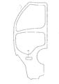
従来は、自動車の製造時に、ボデーを構成する板金の必要とされる個所に手作業で樹脂シートを貼り付けていた。図1は、自動車のボデーの側部外板を構成するサイドメンバー1を示しており、従来は、かかるサイドメンバー1より成る板金と他の板金を組み付ける前に、該サイドメンバー1の車内側となる面に樹脂シート2を手作業によって貼り付けていた。このサイドメンバー1に対して、他の板金を組み付けて、これらを溶接することによりボデーを完成させ、そのボデーに塗装を施すことにより、樹脂シート2を外部から目視できないように覆い隠す。
Conventionally, at the time of manufacturing an automobile, a resin sheet is manually attached to a place where a sheet metal constituting the body is required. FIG. 1 shows a side member 1 that constitutes a side outer plate of a body of an automobile. Conventionally, before assembling a sheet metal made of the side member 1 and another sheet metal, The
上述のように、従来は、自動車のボデーを構成する板金に樹脂シートを手作業で貼り付けていたため、その作業に従事する作業者が必要であり、自動車製造時の省力化の妨げとなっていた。 As described above, conventionally, since a resin sheet is manually attached to a sheet metal constituting a body of an automobile, an operator engaged in the work is necessary, which is an obstacle to labor saving at the time of automobile manufacture. It was.
本発明の目的は、自動車の製造時の省力化をより一層進めるべく、自動車のボデーを構成する板金に自動的に樹脂シートを貼り付けることのできる樹脂シート貼着装置を提供することにある。 The objective of this invention is providing the resin sheet sticking apparatus which can affix a resin sheet automatically to the sheet metal which comprises the body of a motor vehicle, in order to further promote labor saving at the time of manufacture of a motor vehicle.
本発明は、粘着材を介して樹脂シートが接合されている離型紙を搬送する無端状の搬送ベルトと、該離型紙の先端部が前記搬送ベルトを出たときに、該先端部を加圧して、該離型紙を曲折させる離型紙加圧装置と、離型紙が曲折することにより該離型紙から剥離された粘着剤付きの樹脂シートを支持するシート支持体と、該シート支持体上の樹脂シートを自動車のボデーを構成する板金上に搬送するシート搬送手段と、該板金上に載置された樹脂シートを加圧する加圧部材とを具備し、前記樹脂シートが接合された離型紙は、該離型紙が前記搬送ベルトの表面に接触した状態で当該搬送ベルトにより搬送されると共に、該離型紙から剥離された粘着剤付きの樹脂シートは、その粘着剤が前記シート支持体に接触した状態で該シート支持体に支持され、前記シート搬送手段は、前記樹脂シートに接触して内部の空気が吸引されることにより該樹脂シートを吸着する複数の真空吸着装置を有し、該シート搬送手段によって樹脂シートを前記板金の上方に搬送した後、該樹脂シートと板金の間に空気が封じ込められないように、前記複数の真空吸着装置の真空状態を順次1つずつ解除して該樹脂シートを各真空吸着装置から順次離脱し、次いで前記加圧部材により、板金上に載置された樹脂シートを加圧して、該樹脂シートを粘着剤を介して板金面に接合することを特徴とする樹脂シート貼着装置を提案する。 The present invention provides an endless conveyance belt that conveys a release paper to which a resin sheet is bonded via an adhesive material, and pressurizes the leading edge when the leading edge of the release paper exits the conveyance belt. A release paper pressurizing device for bending the release paper, a sheet support for supporting the resin sheet with the adhesive peeled off from the release paper when the release paper is bent, and a resin on the sheet support Sheet release means for conveying the sheet onto the sheet metal constituting the body of the automobile, and a pressure member that presses the resin sheet placed on the sheet metal, the release paper to which the resin sheet is bonded, The release sheet is transported by the transport belt in contact with the surface of the transport belt, and the adhesive-attached resin sheet peeled from the release paper is in a state where the adhesive is in contact with the sheet support. To support the sheet support. And the sheet conveying means has a plurality of vacuum suction devices that adsorb the resin sheet by being in contact with the resin sheet and sucking air therein, and the sheet conveying means removes the resin sheet from the sheet metal. After transporting upward, the vacuum state of the vacuum suction devices is released one by one in order so that air is not confined between the resin sheets and the sheet metal, and the resin sheets are sequentially detached from the vacuum suction devices. Then, a resin sheet sticking apparatus is proposed, in which the pressure sheet pressurizes the resin sheet placed on the sheet metal and joins the resin sheet to the sheet metal surface via an adhesive. .
その際、前記シート支持体上に樹脂シートが載置されたとき、該樹脂シートに一体に接合されている粘着剤の一部が前記シート支持体に接触するように、該シート支持体の表面が形成されていると有利である。 At that time, when the resin sheet is placed on the sheet support, the surface of the sheet support is arranged such that a part of the adhesive integrally bonded to the resin sheet comes into contact with the sheet support. Is advantageously formed.
また、上記樹脂シート貼着装置において、前記離型紙加圧装置は、前記搬送ベルトの上方に位置する軸に支持された一対のアームと、両アームに掛け渡された加圧ローラとを具備し、該一対のアームは、前記加圧ローラと共に、前記搬送ベルトにより搬送される離型紙よりも上方の退避位置と、前記加圧ローラが離型紙を加圧して離型紙を曲折させる加圧位置との間を回動可能に前記軸に支持されていると有利である。 In the resin sheet sticking apparatus, the release paper pressurizing device includes a pair of arms supported by a shaft positioned above the transport belt, and a pressure roller spanned between the arms. The pair of arms are, together with the pressure roller, a retracted position above the release paper conveyed by the conveyance belt, and a pressure position where the pressure roller presses the release paper and bends the release paper. It is advantageous if it is supported on the shaft so as to be pivotable between the two.
さらに、上記樹脂シート貼着装置において、前記搬送ベルトに支持されて搬送される離型紙と該離型紙上の樹脂シートを加圧する無端状の加圧ベルトを有し、該加圧ベルトを巻き掛けた1つのローラの軸に、前記一対のアームが回動可能に支持されていると有利である。 Furthermore, the resin sheet sticking apparatus further includes a release paper supported and transported by the transport belt, and an endless pressure belt that pressurizes the resin sheet on the release paper, and the pressure belt is wound around the release paper. It is advantageous if the pair of arms are rotatably supported on a single roller shaft.
また、上記樹脂シート貼着装置において、前記シート支持体は、機枠に不動に固定された固定支持板と、前記一対のアームに固定された可動支持板とを有し、該アームが前記加圧位置を占めたとき、該アームに固定された可動支持板の上面と前記固定支持板の上面がほぼ面一状態となるように、可動支持板が前記一対のアームに固定されていると有利である。 In the resin sheet sticking apparatus, the sheet support includes a fixed support plate fixed to the machine frame and a movable support plate fixed to the pair of arms. It is advantageous that the movable support plate is fixed to the pair of arms so that the upper surface of the movable support plate fixed to the arm and the upper surface of the fixed support plate are substantially flush with each other when the pressure position is occupied. It is.
本発明によれば、自動車の製造時に、ボデーを構成する板金に樹脂シートを自動的に貼り付けることができるので、自動車の製造時の省力化を一層進めることができる。 According to the present invention, since a resin sheet can be automatically attached to a sheet metal constituting a body at the time of manufacturing an automobile, labor saving at the time of manufacturing the automobile can be further promoted.
以下、本発明の実施形態例を図面に従って詳細に説明する。 Embodiments of the present invention will be described below in detail with reference to the drawings.
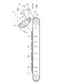
図2乃至図5は、本発明に係る樹脂シート貼着装置のうちの樹脂シート剥離装置3を示す概略図である。この樹脂シート剥離装置3は、離型紙P上の樹脂シートを、その離型紙から分離するための装置である。かかる樹脂シート剥離装置3は、図2に示すように、離型紙Pを搬送する無端状の搬送ベルト4を有している。この搬送ベルト4は、駆動ローラ5と従動ローラ6とに巻き掛けられていて、その両ローラ5,6の間の平坦な上辺7は、ほぼ水平に位置している。離型紙P上には、粘着剤8を介して例えばポリプロピレンより成る樹脂シート2,2A,2B,2Cが接合されている。
2 thru | or FIG. 5 is schematic which shows the resin
離型紙Pは、図8に示すように、図2に示した搬送ベルト4の隣りに多数枚上下に重ねて配置され、その最上位の離型紙Pが、図示していない真空吸着装置により吸着保持されて上方に持ち上げられ、次いでその離型紙Pが図2に示した搬送ベルト4の上方に移送され、引き続きその搬送ベルト4の上辺7上に載置される。このとき搬送ベルト4は停止したままである。
As shown in FIG. 8, the release paper P is arranged adjacent to the
図8に示すように、本例の離型紙Pには、4枚の樹脂シート2,2A,2B,2Cが互いに間隔をあけて接合されていて、かかる離型紙Pの先端部9は、樹脂シート2の貼着されていない余白部となっている。
As shown in FIG. 8, four
図2に示すように、搬送ベルト4の上方には、駆動ローラ10と従動ローラ11,12とに巻き掛けられた無端状の加圧ベルト13が配置されている。前述のように離型紙Pを搬送ベルト4上に載置するとき、加圧ベルト13は図2に示した退避位置を占めているので、離型紙Pを、加圧ベルト13に邪魔されることなく、搬送ベルト4の上に載置することができる。
As shown in FIG. 2, an
図2に示したように、離型紙Pが搬送ベルト4上に載置されると、加圧ベルト13は、駆動ローラ10の中心軸線のまわりに図2に矢印Aで示した方向に回動され、図3に示した加圧位置で停止する。これにより、搬送ベルト4上の離型紙Pとその離型紙P上の樹脂シート2は、加圧ベルト13によって加圧される。
As shown in FIG. 2, when the release paper P is placed on the
次いで搬送ベルト4を巻き掛けた駆動ローラ5が、図示していないモータによって、図3における時計方向に回転駆動されると共に、加圧ベルト13を巻き掛けた駆動ローラ10が、同じく図示していないモータによって、図3における反時計方向に回転駆動される。これにより、搬送ベルト4と加圧ベルト13は、それぞれ矢印B,C方向に走行駆動され、搬送ベルト4上の離型紙Pと樹脂シート2が、加圧ベルト13によって加圧されながら、矢印D方向に搬送される。その際、樹脂シート2,2A,2B,2Cが接合された離型紙Pは、その離型紙Pの方が搬送ベルト4の表面に接触した状態で、その搬送ベルト4によって搬送される。
Next, the
上述のように、本例の樹脂シート貼着装置は、粘着剤8を介して樹脂シート2が接合されている離型紙Pを搬送する搬送ベルト4を有していると共に、その搬送ベルト4に支持されて搬送される離型紙Pと、その離型紙P上の樹脂シート2を加圧する無端状の加圧ベルト13を有している。これにより、搬送ベルト4上の離型紙Pの浮き上がりを阻止しつつ、確実にその離型紙Pを搬送することができる。
As described above, the resin sheet sticking apparatus of the present example includes the
図9は、図3に示した加圧ベルト13と、これに関連する構成要素を、図3の矢印IX方向に見た概略平面図である。図3及び図9に示すように、前述の駆動ローラ10と2本の従動ローラ11,12は、互いに平行に延びていて、駆動ローラ10を固定支持した軸14の長手方向各端部は、図示していない軸受を介して、装置の機枠15に回転自在に支持されている。また、この軸14の各端部は支持版16,17を貫通し、従動ローラ11,12を固定支持した各軸18,19の長手方向各端部は各支持板16,17に回転自在に支持されている。軸14は、各支持板16,17に対して自由に回転することができる。また、駆動ローラ10と2本の従動ローラ11,12には、3本の加圧ベルト13が巻き掛けられている。図9以外の図には、上述の支持板16,17の図示は省略されている。
FIG. 9 is a schematic plan view of the
図9に示した支持板16,17には、図示していない駆動装置が連結され、その駆動装置の作動によって、加圧ベルト13と、そのベルト13を巻き掛けた従動ローラ11,12が、図2に示した退避位置と、図3に示した加圧位置との間を回動することができる。
A driving device (not shown) is connected to the
また、図2及び図3に示すように、搬送ベルト4の近傍には、離型紙加圧装置20が設けられている。この離型紙加圧装置20は、図9にも示すように、互いに離間して位置する一対のアーム21,22と、その両アーム21,22の先端部に掛け渡された加圧ローラ23とを有し、これらのアーム21,22の基端部は、搬送ベルト4の上方に位置する軸に回動可能に支持されている。図示した例では、前述の加圧ベルト13を巻き掛けた1つのローラ10の軸14に、一対のアーム21,22の基端部が回動可能に支持されている。軸14が、駆動ローラ10とアーム21,22を共に支持しているのである。
Further, as shown in FIGS. 2 and 3, a release
上述したアーム21,22にも図示していない駆動装置が連結され、その駆動装置が作動することによって、アーム21,22と加圧ローラ23より成る離型紙加圧装置20は、軸14のまわりに、図2及び図3に示した退避位置と、図4に示した加圧位置との間を回動することができる。
A drive device (not shown) is also connected to the above-described
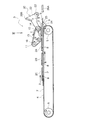
また、図2乃至図5に示すように、搬送ベルト4の離型紙搬送方向前端部に隣接してガイド部材24が固定配置され、このガイド部材24の先端部25は鋭角に尖っている。
Further, as shown in FIGS. 2 to 5, a
前述のように、搬送ベルト4上に離型紙Pが載置され、次いで搬送ベルト4と加圧ベルト13がそれぞれ図3に矢印B,Dで示した方向に動き始めたとき、一対のアーム21,22は、加圧ローラ23と共に、搬送ベルト4により搬送される離型紙Pよりも上方の図2及び図3に示した退避位置を占めている。搬送ベルト4により搬送される離型紙Pの先端部9、すなわち樹脂シート2の存在しない先端領域が、図3に示したように、搬送ベルト4とガイド部材24の先端部25を出たとき、アーム21,22は、加圧ローラ23と共に、軸14のまわりに矢印E方向に回動し、図4に示した加圧位置で停止する。これにより、離型紙Pは、加圧ローラ23により加圧されて図4に示したように曲折され、加圧ローラ23と搬送ベルト4との間に挟み込まれる。このとき、加圧ローラ23は、図示していないモータによって、図4における反時計方向に回転駆動される。このため、離型紙Pは、加圧ローラ23と搬送ベルト4に挟持されながら、図4に矢印Fで示した方向に引張られる。
As described above, when the release paper P is placed on the
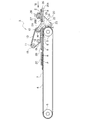
上述のように離型紙Pが引張られるに従って、その離型紙P上の樹脂シート2の先端部は、ガイド部材24の先端部25に至る。このときガイド部材24の先端部25は鋭角に尖っているので、樹脂シート2は、粘着剤8と共に離型紙Pから剥がされながら、引き続き図4に矢印Dで示した水平方向に移動してシート支持体26上に移行する。樹脂シート2が離型紙Pから完全に剥離されると、その樹脂シート2は、図5に示したように、シート支持体26上に支持されて停止する。このとき、搬送ベルト4と加圧ベルト13は、一旦、作動を停止する。このようにして、自動的に樹脂シート2が粘着剤8と共に離型紙Pから剥離されるのである。その際、離型紙Pから剥離された粘着剤付きの樹脂シート2は、その粘着剤8がシート支持体26に接触した状態で、シート支持体26上に載置される。
As described above, as the release paper P is pulled, the front end portion of the
上述のように、本例の樹脂シート貼着装置は、離型紙Pの先端部9が搬送ベルト4を出たときに、該先端部9を加圧して、その離型紙Pを曲折させる離型紙加圧装置20と、離型紙Pが曲折することにより該離型紙Pから剥離された粘着剤8付きの樹脂シート2を支持するシート支持体26とを有しており、図に一例として示した離型紙加圧装置20は、搬送ベルト4の上方に位置する軸14に支持された一対のアーム21,22と、両アーム21,22に掛け渡された加圧ローラ23とを具備し、その一対のアーム21,22は、加圧ローラ23と共に、搬送ベルト4により搬送される離型紙Pよりも上方の退避位置と、加圧ローラ23が離型紙Pを加圧してその離型紙を曲折させる加圧位置との間を回動可能に軸14に支持されている。
As described above, in the resin sheet sticking apparatus of this example, when the
一方、図1に示したサイドメンバー1と同じく形成されたサイドメンバーが、その車内側の面を上向きにして製造ライン上を搬送され、樹脂シート貼着位置で停止する。かかるサイドメンバー上に、図5に示したシート支持体26上の樹脂シート2が次に説明するシート搬送手段によって搬送される。
On the other hand, a side member formed in the same manner as the side member 1 shown in FIG. 1 is conveyed on the production line with its inner surface facing upward, and stops at the resin sheet attaching position. On this side member, the
図5の矢印VI方向に見た図6に示すように、シート搬送手段は、第1乃至第3の複数の真空吸着装置27,27A,27Bを有している。これらの真空吸着装置27,27A,27Bは、全て同じ構造を有していて、図7は第1の真空吸着装置27の断面を示している。図7に示すように、真空吸着装置27は、ゴムにより構成されていて、下部が開口した逆カップ状に形成されていて、かかる真空吸着装置27の上部は、導管28を介して、図示していない吸気装置に接続されている。
As shown in FIG. 6 as viewed in the direction of arrow VI in FIG. 5, the sheet conveying means includes first to third
上述した第1乃至第3の真空吸着装置27,27A,27Bは、図示していないロボットの把持部に取り付けられている。
The first to third
前述のように、離型紙Pから剥離された樹脂シート2が、図5に示したようにシート支持体26上に載置されると、第1乃至第3の真空吸着装置27,27A,27Bが、その樹脂シート2の上方から下降して、第1乃至第3の真空吸着装置27,27A,27Bの下部が、図5乃至図7に示すように樹脂シート2の上面に押し付けられる。次いで、上述の吸気装置の作動によって、第1乃至第3の真空吸着装置27,27A,27Bの内部の空気が吸引されることにより、樹脂シート2が、第1乃至第3の真空吸着装置27,27A,27Bに吸着保持される。この状態で、図示していないロボットによって、真空吸着装置27,27A,27Bと共に、樹脂シート2が図10の(a)に示すように、製造ライン上で停止したサイドメンバー1の上方に搬送される。
As described above, when the
次いで、第1乃至第3の真空吸着装置27,27A,27Bのうちの第1の真空吸着装置27の内部の真空状態が解除される。このため、図10の(b)に示すように、それまで第1の真空吸着装置27によって吸着保持されていた樹脂シート2の部分が、その樹脂シート2と粘着剤8の自重によってサイドメンバー1の上に落ちる。
Next, the vacuum state inside the first
次いで第1の真空吸着装置27の隣りの第2の真空吸着装置27Aの内部の真空状態が解除される。これにより、図10の(c)に示したように、それまで第2の真空吸着装置27Aによって吸着保持されていた樹脂シート2の部分が、その樹脂シート2と粘着剤8の自重によって、サイドメンバー1上に落ちる。
Next, the vacuum state inside the second
引き続き、第3の真空吸着装置27B内の真空状態が解除され、これによって図10の(d)に示すように、それまで第3の真空吸着装置27Bによって吸着保持されていた樹脂シート2の部分も、その樹脂シート2と粘着剤8の自重によって、サイドメンバー1上に落下し、これによって樹脂シート2の全体が、粘着剤8と共にサイドメンバー1上に載置される。
Subsequently, the vacuum state in the third
上述のように、隣り合う真空吸着装置27,27A,27Bの真空状態が順次1つずつ解除されるので、樹脂シート2の全体がサイドメンバー上に載置されたとき、その樹脂シート2とサイドメンバー1の間に、空気が封じ込められることはない。
As described above, since the vacuum state of the adjacent
次いで、図10の(e)に示すように、図示していないロボットの把持部に取り付けられた加圧部材の一例である押圧ローラ29が、サイドメンバー1上に載置された樹脂シート2の上面を転動して、その樹脂シート2を、板金の一例であるサイドメンバー1上に加圧する。これにより樹脂シート2は、粘着剤8を介して、サイドメンバー1の面に貼着される。
Next, as shown in FIG. 10E, a
上述のように、本例の樹脂シート貼着装置は、シート支持体26上の樹脂シート2を自動車のボデーを構成する板金の一例であるサイドメンバー1上に搬送するシート搬送手段と、そのサイドメンバー1上に載置された樹脂シート2を加圧する加圧部材の一例である押圧ローラ29とを具備し、このシート搬送手段は、樹脂シート2に接触して内部の空気が吸引されることにより該樹脂シートを吸着する複数の真空吸着装置27,27A,27Bを有し、該シート搬送手段によって樹脂シート2をサイドメンバー1の上方に搬送した後、該樹脂シート2とサイドメンバー1の間に空気が封じ込められないように、複数の真空吸着装置27,27A,27Bの真空状態を順次1つずつ解除して該樹脂シート2を各真空吸着装置27,27A,27Bから順次離脱し、次いで前記加圧部材の一例である押圧ローラ29により、サイドメンバー1上に載置された樹脂シート2を加圧して、該樹脂シート2を粘着剤8を介してサイドメンバー面に接合するように構成されている。
As described above, the resin sheet sticking apparatus of the present example includes a sheet conveying unit that conveys the
上述のようにして、離型紙P上の一番目の樹脂シート2が離型紙Pから剥離されて、その樹脂シート2がサイドメンバー1に貼り付けられるが、離型紙P上の二番目以降の樹脂シート2A,2B,2Cも全く同様にして離型紙Pから剥離され、その各樹脂シート2A,2B,2Cが、順次製造ライン上を送られてくるサイドメンバーに貼り付けられる。離型紙P上の全ての樹脂シート2,2A,2B,2Cが剥離されると、その離型紙Pは下方に落下する。また、加圧ベルト13と離型紙加圧装置20が再び図2に示した退避位置に回動し、次の離型紙が搬送ベルト4上に載せられ、その離型紙上の各樹脂シートが前述したところと全く同様にして順次離型紙から剥離されてサイドメンバーに貼り付けられる。
As described above, the
ところで、図5及び図6に示したように、シート支持体26上の樹脂シート2を第1乃至第3の真空吸着装置27,27A,27Bに吸着させて、その樹脂シート2を上方に持ち上げるとき、樹脂シート2に積層されている粘着剤8がシート支持体26の表面に強く接合していたとすると、樹脂シート2をシート支持体26から分離して、そのシート2を上方に持ち上げることができなくなるおそれがある。そこで、本例のシート支持体26は、その上面が離型性に優れたテフロン(登録商標)によってコートされていると共に、その上面にギザギザ状の凹凸が形成されている。このため、粘着剤8がシート支持体26に接触する面積が小さくなり、粘着剤8とシート支持体との接合力を小さくすることができるので、第1乃至第3の真空吸着装置27,27A,27Bを上昇させたとき、粘着剤8は容易にシート支持体26から分離され、確実に樹脂シート2を粘着剤8と共に上方に持ち上げることができる。
Incidentally, as shown in FIGS. 5 and 6, the
シート支持体26の上面に凹凸を形成する代わりに、そのシート支持体にスリット状の多数の孔を形成してもよい。要は、シート支持体26上に樹脂シート2を載置したとき、その樹脂シート2に一体に接合されている粘着剤8の全体ではなく、その一部だけがシート支持体26に接触するように、該シート支持体26の表面を形成するのである。
Instead of forming irregularities on the upper surface of the
ところで、シート支持体26は、図5に示したように、ガイド部材24に隣接して配置されるものであり、そのガイド部材24の近傍を、離型紙加圧装置20が回動するので、シート支持体26の全体が装置の機枠に固定されていたとすると、その離型紙加圧装置20の加圧ローラ23が当該シート支持体26に干渉するおそれがある。
Incidentally, as shown in FIG. 5, the
そこで、本例の樹脂シート貼着装置においては、図1乃至図5に示すように、シート支持体26が、装置の機枠に不動に固定された固定支持板26Aと、前述の一対のアーム21,22に固定された可動支持板26B(図9も参照)とから構成されていて、アーム21,22が図4及び図5に示した加圧位置を占めたとき、そのアーム21,22に固定された可動支持板26Bの上面と固定支持板26Aの上面がほぼ面一状態となるように、可動支持板26Bが一対のアーム21,22に固定されている。これにより、離型紙加圧装置20がシート支持体に干渉することはなく、しかもシート支持体26は、その本来の機能を支障なく果たすことができる。
Therefore, in the resin sheet sticking apparatus of this example, as shown in FIGS. 1 to 5, the
本発明は、サイドメンバー以外の板金に樹脂シートを貼り付ける樹脂シート貼着装置にも広く適用できるものである。 The present invention can be widely applied to a resin sheet sticking apparatus for sticking a resin sheet to a sheet metal other than the side member.
2 樹脂シート
4 搬送ベルト
8 粘着剤
9 先端部
10 ローラ
13 加圧ベルト
14 軸
20 離型紙加圧装置
21,22 アーム
23 加圧ローラ
26 シート支持体
26A 固定支持板
26B 可動支持板
27,27A,27B 真空吸着装置
P 離型紙
DESCRIPTION OF
Claims (5)
Priority Applications (1)
| Application Number | Priority Date | Filing Date | Title |
|---|---|---|---|
| JP2008190779A JP4754606B2 (en) | 2008-07-24 | 2008-07-24 | Resin sheet sticking device |
Applications Claiming Priority (1)
| Application Number | Priority Date | Filing Date | Title |
|---|---|---|---|
| JP2008190779A JP4754606B2 (en) | 2008-07-24 | 2008-07-24 | Resin sheet sticking device |
Publications (2)
| Publication Number | Publication Date |
|---|---|
| JP2010024038A true JP2010024038A (en) | 2010-02-04 |
| JP4754606B2 JP4754606B2 (en) | 2011-08-24 |
Family
ID=41730205
Family Applications (1)
| Application Number | Title | Priority Date | Filing Date |
|---|---|---|---|
| JP2008190779A Expired - Fee Related JP4754606B2 (en) | 2008-07-24 | 2008-07-24 | Resin sheet sticking device |
Country Status (1)
| Country | Link |
|---|---|
| JP (1) | JP4754606B2 (en) |
Cited By (4)
| Publication number | Priority date | Publication date | Assignee | Title |
|---|---|---|---|---|
| WO2014069586A1 (en) | 2012-11-05 | 2014-05-08 | 日東電工株式会社 | Method for affixing adhesive sheets and device for affixing adhesive sheets |
| JP2015141992A (en) * | 2014-01-28 | 2015-08-03 | 株式会社Screenホールディングス | Peeling device and peeling method |
| KR101665971B1 (en) * | 2016-08-10 | 2016-10-13 | (주)글로벌 로보틱스 | Automotive foam pad attachment |
| US10131090B2 (en) | 2014-03-19 | 2018-11-20 | Nitto Denko Corporation | Adhesive sheet pasting method and adhesive sheet pasting apparatus |
Citations (3)
| Publication number | Priority date | Publication date | Assignee | Title |
|---|---|---|---|---|
| JP2002338136A (en) * | 2001-05-16 | 2002-11-27 | Bridgestone Corp | Transferring method and device for pressure sensitive adhesive seal |
| JP2003023063A (en) * | 2001-07-09 | 2003-01-24 | Lintec Corp | Lamination apparatus |
| JP2004189391A (en) * | 2002-12-10 | 2004-07-08 | Fuji Photo Film Co Ltd | Protective sheet separating device |
-
2008
- 2008-07-24 JP JP2008190779A patent/JP4754606B2/en not_active Expired - Fee Related
Patent Citations (3)
| Publication number | Priority date | Publication date | Assignee | Title |
|---|---|---|---|---|
| JP2002338136A (en) * | 2001-05-16 | 2002-11-27 | Bridgestone Corp | Transferring method and device for pressure sensitive adhesive seal |
| JP2003023063A (en) * | 2001-07-09 | 2003-01-24 | Lintec Corp | Lamination apparatus |
| JP2004189391A (en) * | 2002-12-10 | 2004-07-08 | Fuji Photo Film Co Ltd | Protective sheet separating device |
Cited By (6)
| Publication number | Priority date | Publication date | Assignee | Title |
|---|---|---|---|---|
| WO2014069586A1 (en) | 2012-11-05 | 2014-05-08 | 日東電工株式会社 | Method for affixing adhesive sheets and device for affixing adhesive sheets |
| JP2014091618A (en) * | 2012-11-05 | 2014-05-19 | Nitto Denko Corp | Adhesive sheet sticking method and adhesive sheet sticking device |
| US9227812B2 (en) | 2012-11-05 | 2016-01-05 | Nitto Denko Corporation | Adhesive sheet joining method and adhesive sheet joining apparatus |
| JP2015141992A (en) * | 2014-01-28 | 2015-08-03 | 株式会社Screenホールディングス | Peeling device and peeling method |
| US10131090B2 (en) | 2014-03-19 | 2018-11-20 | Nitto Denko Corporation | Adhesive sheet pasting method and adhesive sheet pasting apparatus |
| KR101665971B1 (en) * | 2016-08-10 | 2016-10-13 | (주)글로벌 로보틱스 | Automotive foam pad attachment |
Also Published As
| Publication number | Publication date |
|---|---|
| JP4754606B2 (en) | 2011-08-24 |
Similar Documents
| Publication | Publication Date | Title |
|---|---|---|
| KR101250656B1 (en) | Device for transferring/fixing small piece member | |
| JP5778116B2 (en) | Adhesive sheet attaching method and adhesive sheet attaching apparatus | |
| JP4754606B2 (en) | Resin sheet sticking device | |
| JP6151880B2 (en) | Sheet sticking device and sticking method | |
| JP4816751B2 (en) | Adhesive sheet piece separating apparatus and adhesive sheet piece separating method | |
| JP2007277010A (en) | Device for switching first belt-like raw material sheet to second belt-like raw material sheet | |
| CN211195251U (en) | Full-automatic net cage laminating machine | |
| JP5058026B2 (en) | Sheet connection device | |
| KR101639049B1 (en) | Temper and basis weight of the other paper high speed lamination device | |
| JP5775736B2 (en) | Sheet sticking device and sticking method | |
| CN107636821B (en) | Sheet peeling device and peeling method | |
| JP5820214B2 (en) | Sheet sticking device and sheet sticking method | |
| JP5785430B2 (en) | Sheet sticking device and sticking method | |
| JP4630921B2 (en) | Unfoamed sheet sticking device | |
| JP7000958B2 (en) | Seal member separation device and seal member separation method | |
| JP4676776B2 (en) | Method for manufacturing printed wiring board | |
| JP6445882B2 (en) | Sheet transfer apparatus and transfer method | |
| JP5775735B2 (en) | Sheet sticking device and sticking method | |
| JP2011148576A (en) | Sheet carrying device and film insert mold manufacturing device | |
| JP4640059B2 (en) | Sheet substrate supply device | |
| JP2008184230A (en) | Paper splicing device and corrugating machine | |
| JP2012229033A (en) | Apparatus for sticking sheet, and method of sticking | |
| JP2012140150A (en) | Label sticking device | |
| KR200169921Y1 (en) | A plastic device of a support plate of cake for cake box | |
| CN213536502U (en) | Sucking disc formula loading attachment and printing machine |
Legal Events
| Date | Code | Title | Description |
|---|---|---|---|
| A977 | Report on retrieval |
Free format text: JAPANESE INTERMEDIATE CODE: A971007 Effective date: 20100625 |
|
| A131 | Notification of reasons for refusal |
Free format text: JAPANESE INTERMEDIATE CODE: A131 Effective date: 20101014 |
|
| A521 | Written amendment |
Free format text: JAPANESE INTERMEDIATE CODE: A523 Effective date: 20101126 |
|
| TRDD | Decision of grant or rejection written | ||
| A01 | Written decision to grant a patent or to grant a registration (utility model) |
Free format text: JAPANESE INTERMEDIATE CODE: A01 Effective date: 20110524 |
|
| A01 | Written decision to grant a patent or to grant a registration (utility model) |
Free format text: JAPANESE INTERMEDIATE CODE: A01 |
|
| A61 | First payment of annual fees (during grant procedure) |
Free format text: JAPANESE INTERMEDIATE CODE: A61 Effective date: 20110525 |
|
| FPAY | Renewal fee payment (event date is renewal date of database) |
Free format text: PAYMENT UNTIL: 20140603 Year of fee payment: 3 |
|
| R150 | Certificate of patent or registration of utility model |
Free format text: JAPANESE INTERMEDIATE CODE: R150 |
|
| FPAY | Renewal fee payment (event date is renewal date of database) |
Free format text: PAYMENT UNTIL: 20140603 Year of fee payment: 3 |
|
| S531 | Written request for registration of change of domicile |
Free format text: JAPANESE INTERMEDIATE CODE: R313531 |
|
| S533 | Written request for registration of change of name |
Free format text: JAPANESE INTERMEDIATE CODE: R313533 |
|
| FPAY | Renewal fee payment (event date is renewal date of database) |
Free format text: PAYMENT UNTIL: 20140603 Year of fee payment: 3 |
|
| R350 | Written notification of registration of transfer |
Free format text: JAPANESE INTERMEDIATE CODE: R350 |
|
| R250 | Receipt of annual fees |
Free format text: JAPANESE INTERMEDIATE CODE: R250 |
|
| R250 | Receipt of annual fees |
Free format text: JAPANESE INTERMEDIATE CODE: R250 |
|
| R250 | Receipt of annual fees |
Free format text: JAPANESE INTERMEDIATE CODE: R250 |
|
| LAPS | Cancellation because of no payment of annual fees |