JP2010023262A - Laminating device - Google Patents
Laminating device Download PDFInfo
- Publication number
- JP2010023262A JP2010023262A JP2008184509A JP2008184509A JP2010023262A JP 2010023262 A JP2010023262 A JP 2010023262A JP 2008184509 A JP2008184509 A JP 2008184509A JP 2008184509 A JP2008184509 A JP 2008184509A JP 2010023262 A JP2010023262 A JP 2010023262A
- Authority
- JP
- Japan
- Prior art keywords
- base material
- substrate
- adhesive
- sheet
- feed
- Prior art date
- Legal status (The legal status is an assumption and is not a legal conclusion. Google has not performed a legal analysis and makes no representation as to the accuracy of the status listed.)
- Granted
Links
Images


Landscapes
- Decoration By Transfer Pictures (AREA)
- Making Paper Articles (AREA)
Abstract
Description
この発明は、シールやラベル等の連続シート状基材に金属箔を転写する貼り合わせ装置に関するものである。 The present invention relates to a laminating apparatus for transferring a metal foil onto a continuous sheet-like substrate such as a seal or a label.
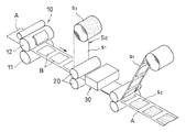
連続シート状基材に金属箔を転写する転写装置(貼り合わせ装置)として、特許文献1に記載されたものが従来から知られている。この貼り合わせ装置においては、図4に示すように、基材Aの移送路に圧胴11および版胴12を有する印刷ユニット10を設け、その印刷ユニット10により上記基材Aの片面に紫外線硬化型の粘着剤Bを印刷し、離型シートs1の片面に金属箔s2が設けられた転写シートS0を、その金属箔s2が上記基材Aの印刷面と対向するよう重ね合わせて、上下一対のニップロール20による挟圧により基材Aに転写シートS0を貼り合わせ、その貼り合わせによって形成されるシート積層体S1の片面に紫外線照射ユニット30から出射される紫外線を照射し、粘着剤Bの硬化により金属箔s2を固着させた後、基材Aから離型シートs1を剥離して、粘着剤B上に金属箔s2を転写するようにしている。
As a transfer device (bonding device) for transferring a metal foil to a continuous sheet-like substrate, a device described in
ところで、上記貼り合わせ装置においては、粘着剤の印刷が、印刷ユニット10の圧胴11および版胴12を基材Aの移送方向に連続回転させて印刷を行う連続輪転印刷方式によるものであるため、粘着剤は版胴12の周長に等しいピッチで印刷されることになり、印刷された粘着剤B間に多くの損紙が生じるという不都合がある。
By the way, in the said bonding apparatus, since printing of an adhesive is based on the continuous rotary printing system which prints by continuously rotating the
ここで、輪転印刷方式には、上記のような連続輪転印刷方式の他に、間歇輪転印刷方式が存在する。この間歇輪転印刷方式においては、一対の送りロールの間歇回転により基材を間歇送りし、その基材の移送時に印刷を行う間歇輪転印刷方式が存在する。この場合、印刷物間の間隔は非常に小さいものとなるため、損紙を少なくすることができるが、停止状態の送りロールが版胴の周速に等しくなるまでの立ち上がり回転時、および、印刷完了後において等速回転していた送りロールが停止するまでの立下り回転時にも基材が移送されるため、損紙を完全に無くすことはできない。 Here, in the rotary printing method, there is an intermittent rotary printing method in addition to the continuous rotary printing method as described above. In this intermittent web printing system, there is a intermittent web printing system in which a substrate is intermittently fed by intermittent rotation of a pair of feed rolls and printing is performed when the substrate is transferred. In this case, since the interval between printed materials becomes very small, it is possible to reduce paper loss, but at the time of rising rotation until the stopped feed roll becomes equal to the peripheral speed of the plate cylinder, and printing is completed. Since the base material is also transferred at the time of falling rotation until the feed roll that has been rotated at a constant speed later stops, the waste paper cannot be completely eliminated.
損紙を最小限に抑えるため、版胴に取付けられた印版が印刷を完了して次の印刷が行なわれるまでの間に、送りロールの立ち上がり回転および立下り回転による基材の送り量に略相当する量だけ基材を後退させるようにした間歇輪転印刷方式が提案されている。 In order to minimize waste paper, the feed amount of the base material by the rising and falling rotations of the feed roll is between the printing plate attached to the plate cylinder and the next printing is completed. There has been proposed an intermittent web printing method in which the substrate is moved backward by a substantially equivalent amount.
上記のような基材の前進送り後に、その基材を後退動させるようにした間歇輪転印刷方式を貼り合わせ装置に採用すると、損紙を最小限に抑えることができ、基材や転写シートの有効利用に効果を挙げることができる。 Adopting the intermittent web printing method in which the base material is moved backward after the forward feeding of the base material as described above can minimize the waste paper, and the base material and the transfer sheet. Effective use can be achieved.
ところで、基材の前進送りと後退とを繰り返し行なう間歇輪転印刷方式を特許文献1に記載された貼り合わせ装置に採用した場合、基材を後退させた時、一旦、ニップロールを通過した未硬化の粘着剤がニップロールの上流側に引き戻されることになる。この場合、転写シートの金属箔は未硬化の粘着剤との接着によって離型シートから不完全な状態で剥離されることになるため、平滑度の悪い、光沢の無い金属箔が基材に転写されることになり、価値の低い商品が形成されるという問題が発生する。
By the way, when the intermediate rotary printing method in which the base material is repeatedly fed forward and backward is employed in the bonding apparatus described in
また、貼り合わせ装置には、上記のような金属箔の転写装置以外に、インキ印刷された基材のインキ印刷面上に艶出し用のニスを印刷し、そのニスの平滑性を保持するためにフィルムを貼り合わせ、ニスの硬化後にフィルムを剥離させるようにしたものや、インキ印刷された基材のインキ印刷面上に糊を印刷し、その糊を介してラミネートフィルムを基材に接着し、上記ラミネートフィルムをインキ印刷面の周囲に沿ってハーフカットし、その抜きかすと成るラミネートフィルムを基材から剥離させるようにしたものもある。 In addition to the metal foil transfer device as described above, the laminating device prints a varnish for polishing on the ink-printed surface of an ink-printed substrate, and maintains the smoothness of the varnish. A paste is printed on the ink-printed surface of an ink-printed substrate that has been bonded to a film and the film is peeled after the varnish is cured, and the laminate film is adhered to the substrate via the adhesive. In some cases, the laminate film is half-cut along the periphery of the ink printing surface, and the laminate film to be removed is peeled off from the substrate.
上記のような貼り合わせ装置において、基材の前進送りと後退送りとを繰り返し行なう間歇輪転印刷方式を採用すると、基材を後退させた時、一旦、ニップロールを通過した未硬化のニスあるいは糊がニップロールの上流側に引き戻されることになり、基材とフィルムの剥離境界位置において、ニスあるいは糊に線状の模様が形成され、価値の低い商品が形成されるという問題が発生する。 In the laminating apparatus as described above, when the intermediate rotary printing method in which the base material is repeatedly fed forward and backward is adopted, when the base material is retracted, the uncured varnish or glue that has once passed through the nip roll is temporarily removed. It will be pulled back to the upstream side of the nip roll, and at the peeling boundary position between the substrate and the film, a linear pattern is formed on the varnish or glue, resulting in the formation of a low-value product.
この発明の課題は、価値の高い商品を得ることができる損紙の発生の少ない貼り合わせ装置を提供することである。 The subject of this invention is providing the bonding apparatus with little generation | occurrence | production of a waste paper which can obtain a high value goods.
上記の課題を解決するため、第1の発明においては、連続シート状基材の移送路に、正逆回転される上下一対の送りロールの2組を基材の移送方向に間隔をおいて設け、その2組の一対の送りロール間に、上流側から順に、基材の片面に対して紫外線硬化型粘着剤を印刷する粘着剤塗布用の輪転式印刷ユニットと、離型シートの片面に金属箔が設けられた転写シートを、その金属箔が印刷ユニットにより印刷された粘着剤に接着されるよう前記基材に貼り合わせてシート積層体を形成する一対のニップロールと、前記シート積層体の片面側から紫外線を照射して粘着剤を硬化させる紫外線照射ユニットと、前記シート積層体から離型シートを剥離させる剥離手段とを設け、前記2組の一対の送りロールを基材の前進送り方向に間歇的に等速回転させて基材を下流側に向けて移動させる前進送り動作と、その前進停止後に送りロールを逆転させて前進送り時の送りロールの立ち上がり回転および立下り回転による基材の送り量に略相当する量だけ基材を上流側に引き戻す後退送り動作を繰り返し行い、前進時に前記印刷ユニットにより粘着剤を印刷し、前記紫外線照射ユニットからの紫外線の照射により粘着剤を硬化させて金属箔を粘着剤上に転写するようにした貼り合わせ装置において、前記一対のニップロールを回転自在に支持する支持体を基材の移送方向に移動自在に支持し、前記基材の後退時に、その支持体を基材と同方向に同じ速度でもって同量だけ後退動させる移動装置を設けた構成を採用したのである。 In order to solve the above problems, in the first invention, two pairs of a pair of upper and lower feed rolls that are rotated in the forward and reverse directions are provided in the transfer path of the continuous sheet-like substrate at intervals in the transfer direction of the substrate. A rotary printing unit for applying an adhesive that prints an ultraviolet curable adhesive on one side of the base material in order from the upstream side between the two pairs of feed rolls, and a metal on one side of the release sheet A pair of nip rolls that form a sheet laminate by bonding the transfer sheet provided with the foil to the substrate so that the metal foil is adhered to the adhesive printed by the printing unit, and one side of the sheet laminate An ultraviolet irradiation unit for irradiating ultraviolet rays from the side to cure the adhesive and a peeling means for peeling the release sheet from the sheet laminate are provided, and the two pairs of feed rolls are moved in the forward feed direction of the substrate. Intermittent constant speed This is roughly equivalent to the forward feed operation that moves the base material toward the downstream side, and the feed amount of the base material by the rising rotation and falling rotation of the feed roll during forward feed by reversing the feed roll after the forward stop. Repeat the reverse feed operation that pulls the base material upstream by the amount, prints the adhesive with the printing unit when moving forward, cures the adhesive by irradiating ultraviolet rays from the ultraviolet irradiation unit, and puts the metal foil on the adhesive In the laminating apparatus adapted to transfer to the substrate, a support that rotatably supports the pair of nip rolls is supported so as to be movable in the transfer direction of the substrate. A configuration in which a moving device that moves backward by the same amount at the same speed in the same direction is employed.
上記の構成からなる貼り合わせ装置においては、2組の一対の送りロールの回転により基材の前進と後退とを繰り返し行い、その前進時に印刷ユニットにより粘着剤を印刷し、その印刷面に転写シートを重ね合わせ、ニップロールのニップ圧(挟圧)により基材に転写シートを貼り合わせてシート積層体を形成する。そのシート積層体に紫外線照射ユニットから出射される紫外線を照射して粘着剤を硬化させて金属箔を固着し、その粘着剤の硬化後に離型シートを基材から剥離させて、粘着剤に金属箔を転写する。 In the laminating apparatus having the above-described configuration, the base material is repeatedly advanced and retracted by rotating the two pairs of feed rolls, and the adhesive is printed by the printing unit during the advancement, and the transfer sheet is printed on the printing surface. And a transfer sheet is bonded to the substrate by the nip pressure (nip pressure) of the nip roll to form a sheet laminate. The sheet laminate is irradiated with ultraviolet rays emitted from an ultraviolet irradiation unit to cure the adhesive and fix the metal foil. After the adhesive is cured, the release sheet is peeled off from the base material, and the adhesive is coated with metal. Transfer the foil.
上記のような金属箔の転写において、基材を前進させる場合、2組の一対の送りロールを停止状態から加速し、その周速が印刷ユニットの版胴に取り付けられた印版の周速に等しくなると等速回転させ、その等速回転時に印刷を行う。そして印刷が完了すると減速して停止する。 In the transfer of the metal foil as described above, when the substrate is advanced, the two pairs of feed rolls are accelerated from the stopped state, and the peripheral speed thereof is the peripheral speed of the printing plate attached to the plate cylinder of the printing unit. When they are equal, they are rotated at a constant speed, and printing is performed during the rotation at the constant speed. And when printing is completed, it decelerates and stops.
また、基材を後退させる場合は、上記一対の送りロールの加速による立ち上がり回転時および減速による立下り回転時の基材の送り量に略相当する量だけ基材を上流側に引き戻して、印刷される粘着剤の間隔を小さくし、損紙の発生を抑制する。 Also, when the base material is moved backward, the base material is pulled back to the upstream side by an amount substantially equivalent to the feed amount of the base material at the time of rising rotation by acceleration of the pair of feed rolls and at the time of falling rotation by deceleration. The interval between the adhesives to be reduced is reduced, and the occurrence of damaged paper is suppressed.
また、基材の後退による引き戻し時には、移動装置の作動により一対のニップロールを支持する支持体を基材の後退方向と同方向に同じ速度でもって同量だけ移動させるようにして、基材に印刷された未硬化の粘着剤が一対のニップロールから上流側に引き抜かれるのを防止する。 Also, when pulling back due to the backward movement of the base material, the support device supporting the pair of nip rolls is moved by the same amount at the same speed and in the same direction as the backward direction of the base material by the operation of the moving device. The uncured pressure-sensitive adhesive thus formed is prevented from being drawn upstream from the pair of nip rolls.
このように、基材の後退による引き戻し時に一対のニップロールを支持する支持体を基材の後退方向と同方向に同じ速度でもって同量だけ移動させることにより、転写シートの金属箔が未硬化の粘着剤との接着によって離型シートから不完全な状態で剥離されるのを防止することができる。 Thus, the metal foil of the transfer sheet is uncured by moving the support that supports the pair of nip rolls at the same speed and in the same direction as the backward direction of the base material when the base material is pulled back by the backward movement. It is possible to prevent peeling from the release sheet in an incomplete state due to adhesion with the pressure-sensitive adhesive.
ここで、移動装置として、駆動プーリおよび従動プーリと、その両プーリ間に掛け渡されて、一部に支持体が連結されたベルトからなるものを採用することができる。 Here, as the moving device, it is possible to employ a driving pulley and a driven pulley, and a belt including a belt that is spanned between both pulleys and a support is connected to a part thereof.
上記の課題を解決するために、第2の発明においては、基材としてインキ印刷されたものを用いると共に、第1の発明に係る紫外線硬化型粘着剤に代えて紫外線硬化型ニスを採用して、そのニスをインキ印刷面上に印刷し、かつ、離型シートに代えてフィルムを採用し、そのフィルムによって印刷されたニスの平滑性を保持するようにしたのである。 In order to solve the above problems, in the second invention, an ink-printed substrate is used, and an ultraviolet curable varnish is used instead of the ultraviolet curable adhesive according to the first invention. The varnish was printed on the ink printing surface, and a film was used instead of the release sheet to maintain the smoothness of the varnish printed by the film.
上記第2の発明においては、紫外線の照射によってニスを硬化させた後、フィルムを基材から剥離する。 In the said 2nd invention, after hardening a varnish by irradiation of an ultraviolet-ray, a film is peeled from a base material.
上記の課題を解決するために、第3の発明においては、基材としてインキ印刷されたものを用いると共に、第1の発明に係る紫外線硬化型粘着剤に代えて紫外線硬化型の糊を採用して、その糊をインキ印刷面上に印刷し、かつ、離型シートに代えてラミネートフィルムを採用したのである。 In order to solve the above problems, in the third invention, an ink printed material is used as a base material, and an ultraviolet curable adhesive is employed in place of the ultraviolet curable adhesive according to the first invention. The glue was printed on the ink printing surface, and a laminate film was used instead of the release sheet.
上記第3の発明においては、紫外線の照射によって糊を硬化させた後、ラミネートフィルムをインキ印刷面の周囲に沿ってハーフカットし、その抜きかすと成るラミネートフィルムを基材から剥離させるようにする。 In the third aspect of the invention, after the paste is cured by irradiation of ultraviolet rays, the laminate film is half-cut along the periphery of the ink printing surface, and the laminate film to be removed is peeled off from the substrate. .
上記のように、第1の発明においては、前進と後退とが繰り返し行なわれる基材の後退時に、一対のニップロールを回転自在に支持する支持体を基材と同方向に同じ速度でもって同量だけ後退動させて基材に印刷された未硬化の粘着剤が一対のニップロールから上流側に引き抜かれるのを防止するようにしたので、転写シートの金属箔が未硬化の粘着剤との接着によって離型シートから不完全な状態で剥離されるというようなことがなくなり、上記基材に対して平滑度の高い光沢のある金属箔を転写することができる。 As described above, in the first invention, when the base material is repeatedly advanced and retracted, the support that rotatably supports the pair of nip rolls at the same speed and in the same direction as the base material. The uncured pressure-sensitive adhesive printed on the substrate is prevented from being pulled upstream from the pair of nip rolls, so that the metal foil of the transfer sheet is bonded to the uncured pressure-sensitive adhesive. It is no longer incompletely peeled from the release sheet, and a glossy metal foil with high smoothness can be transferred to the substrate.
また、基材の前進と後退の繰り返しによる間歇輪転印刷方式によって粘着剤の印刷を行なうようにしたので、その粘着剤に転写される金属箔の間隔は小さく、基材および転写シートの損紙の発生を最小限に抑えることができる。 In addition, since the adhesive is printed by the intermittent rotary printing method by repeatedly moving the substrate forward and backward, the interval between the metal foil transferred to the adhesive is small, and the damaged paper of the substrate and the transfer sheet Occurrence can be minimized.
第2の発明および第3の発明においては、基材に印刷されたニスあるいは糊の印刷部位からフィルムやラミネートフィルムが剥離されることがないため、ニスあるいは糊に線状の模様が形成されるという不都合の発生はなく、商品価値の高い商品を得ることができる。 In the second and third inventions, since the film or the laminate film is not peeled off from the printed portion of the varnish or glue printed on the base material, a linear pattern is formed on the varnish or glue. There is no such inconvenience, and a product with a high commercial value can be obtained.
以下、この発明の実施の形態を図1乃至図3に基づいて説明する。図1および図2に示すように、基材ロールR1から引き出された連続シート状の基材Aは紙あるいは合成樹脂シート等からなる。その基材Aの移送路には、一対の第1送りロール1と一対の第2送りロール2とが基材Aの移送方向に間隔をおいて設けられている。一対の第1送りロール1の一方はサーボモータ3で回転駆動される。また、一対の第2送りロール2の一方はサーボモータ4で回転駆動される。
Hereinafter, embodiments of the present invention will be described with reference to FIGS. 1 to 3. As shown in FIGS. 1 and 2, the continuous sheet-like base material A drawn from the base material roll R 1 is made of paper or synthetic resin sheet. In the transfer path of the base material A, a pair of
基材ロールR1から引き出された連続シート状の基材Aは一対の第1送りロール1間に至る前段においてダンサーロール5に掛け渡されてループL1が形成される。なお、ダンサーロール5に代えてサクションボックスによりループを形成するようにしてもよい。
The continuous sheet-like base material A drawn out from the base material roll R 1 is passed over the
第1送りロール1と第2送りロール2間における基材Aの移送路には、上流側から順に、基材Aの片面に対して紫外線硬化型粘着剤を印刷する印刷ユニット10と、シートロールR2から引き出された転写シートS0を基材Aの粘着剤印刷面側に貼り合わせてシート積層体S1を形成する一対のニップロール20と、前記シート積層体S1の片面側から紫外線を照射して粘着剤を硬化させる紫外線照射ユニット30が設けられている。
In the transfer path of the base material A between the
印刷ユニット10は、圧胴11、版胴12およびその版胴12の外周に取り付けられる印版13に粘着剤を供給する供給ロール14とからなり、上記印版13に供給された粘着剤を圧胴11と版胴12間に挿通された基材Aに印刷するようにしている。なお、印刷ユニット10は上記のような凸版印刷式のものに限定されず、オフセット印刷式やグラビア印刷式のものであってもよい。
The
ここで、粘着剤は、エポキシアクリレート、ウレタンアクリレート、アクリル変性ポリエステル等をオリゴマーとし、これに架橋構造・粘度の調整等を目的としたネオベンチルグリコールアクリレート、トリメチロールプロパンアクリレート等のモノマーを配合し、さらに光重合開始剤を配合したものであり、紫外線を照射することによって硬化するようになっている。 Here, the pressure-sensitive adhesive is an epoxy acrylate, urethane acrylate, acrylic modified polyester or the like oligomer, and a monomer such as neoventyl glycol acrylate or trimethylol propane acrylate for the purpose of adjusting the cross-linked structure or viscosity. Further, a photopolymerization initiator is blended, and is cured by irradiating with ultraviolet rays.
転写シートS0は、図3に示すように、透明な合成樹脂シート等からなる離型性を有する離型シートs1と、その片面に設けられた金属箔s2とからなる。金属箔s2は、アルミ二ウム、クロム、アンチモン、銅、銀等の金属やこれらの合金からなり、蒸着法等によって離型シートs1の片面全体に設けられている。 Transfer sheet S 0, as shown in FIG. 3, the release sheet s 1 having releasing property made of a transparent synthetic resin sheet made of a metal foil s 2 Metropolitan provided on the one surface. Metal foil s 2 is Aluminum, chromium, antimony, copper, a metal or an alloy thereof such as silver, it is provided on the entire one surface of the release sheet s 1 by vapor deposition or the like.
上記転写シートS0は、金属箔s2が基材Aの粘着剤印刷面側に対向するようにして一対のニップロール20間に導き出され、その一対のニップロール20の挟圧(ニップ圧)により基材Aに貼り合わされる。その貼り合わせによりシート積層体S1が形成される。 The transfer sheet S 0 is led out between the pair of nip rolls 20 so that the metal foil s 2 faces the adhesive printing surface side of the substrate A, and is based on the clamping pressure (nip pressure) of the pair of nip rolls 20. Affixed to material A. Sheet laminate S 1 is formed by the bonding.
図1に示すように、一対のニップロール20は、支持体21によって両端部が回転自在に支持されている。支持体21は基材Aの移送方向に延びるリニアレール22に沿って移動自在とされ、移動装置23によって基材Aの移送方向に移動される。
As shown in FIG. 1, both ends of the pair of nip rolls 20 are rotatably supported by a
移動装置23は、サーボモータ24によって回転される駆動プーリ25と、従動プーリ26と、その両プーリ25、26間に掛け渡したエンドレスのベルト27とからなり、上記ベルト27の一部に支持体21を連結し、そのベルト27の移動によって支持体21をリニアレール22に沿って移動させるようにしている。
The moving
紫外線照射ユニット30は、紫外線照射ランプからなり、そのランプから出射される紫外線は離型シートs1を透過して粘着剤Bを照射する。その照射によって粘着剤Bが硬化し、金属箔s2が固着される。なお、基材Aが透明なフィルムからなる場合、基材A側に紫外線照射ユニット30を設けるようにしてもよい。
The
図1に示すように、紫外線照射ユニット30と第2送りロール2間には、基材Aから離型シートs1を剥離する剥離手段40が設けられている。剥離手段40は、一対の剥離ロール41からなり、その一対の剥離ロール41の一方に沿って離型シートs1を引き上げることによって、離型シートs1を剥離させるようにしている。剥離後の離型シートs1はドラム42によって巻き取られるようになっている。
As shown in FIG. 1, a peeling means 40 for peeling the release sheet s 1 from the substrate A is provided between the
一対の第2送りロール2を通過した基材Aは、ダンサーロール50に掛け渡されてループL2が形成され、巻取りドラム51に巻き取られるようになっている。
The base material A that has passed through the pair of second feed rolls 2 is stretched around the
実施の形態で示す貼り合わせ装置は上記の構造からなり、基材Aに対する金属箔s2の転写に際しては、一対の第1送りロール1と一対の第2送りロール2とを同期回転させ、その両ロール1、2の正回転と逆回転の繰り返しにより基材Aを下流側に向けて所定量前進させ、その前進後に上流側に向けて所定量後退させて、基材Aを下流側に向けて間歇送りする。
The laminating apparatus shown in the embodiment has the above structure, and when transferring the metal foil s 2 to the base material A, the pair of first feed rolls 1 and the pair of second feed rolls 2 are synchronously rotated, By repeating forward and reverse rotations of both
そして、間歇送りされる基材Aの前進時に印刷ユニット10の一方向に連続回転する版胴12上の印版13により基材Aに粘着剤を印刷する。このように、基材Aを間歇送りすることにより、その基材Aの片面に粘着剤が次々と印刷される。図2のBは印刷された粘着剤を示し、その印刷された粘着剤Bが一対のニップロール20間を通過する際にその上に転写シートS0が重ね合わされ、上記ニップロール20の挟圧により基材Aに貼り合わされてシート積層体S1が形成される。
Then, the adhesive is printed on the substrate A by the
シート積層体S1が紫外線照射ユニット30の位置まで移送されると、紫外線照射ユニット30からの紫外線の照射により粘着剤Bが硬化する。その硬化により転写シートS0の金属箔s2が固着され、剥離ロール41から離型シートs1を引き上げ、その離型シートs1を基材Aから剥離させることにより、粘着剤Bに金属箔s2が転写されることになる。
When the sheet laminate S 1 is transferred to the position of the
なお、粘着剤B上に金属箔s2が転写された基材Aは巻取りドラム51により巻き取られ、一方、基材Aから剥離された離型シートs1はドラム42により巻き取られる。
The base material A having the metal foil s 2 transferred onto the adhesive B is taken up by the take-
ここで、粘着剤の印刷に際しては、一対の第1送りロール1および一対の第2送りロール2を停止状態から加速し、その周速が印刷ユニット10の版胴12に取り付けられた印版13の周速に等しくなると等速回転させ、その等速回転時に印刷を行う。そして、印刷が完了すると減速して停止する。
Here, when printing the adhesive, the pair of first feed rolls 1 and the pair of second feed rolls 2 are accelerated from the stopped state, and the peripheral speed thereof is the
また、基材Aを後退させる場合は、上記一対の第1送りロール1および一対の第2送りロール2の加速による立ち上がり回転時および減速による立下り回転時の基材Aの送り量に略相当する量だけ基材Aを上流側に引き戻し、印刷される粘着剤Bの間隔を小さくして、損紙の発生を抑制する。 Further, when the base material A is moved backward, it substantially corresponds to the feed amount of the base material A during the rising rotation by acceleration of the pair of first feed rolls 1 and the pair of second feed rolls 2 and during the falling rotation by deceleration. The base material A is pulled back to the upstream side by an amount to be reduced, and the interval between the printed adhesives B is reduced to suppress the occurrence of paper loss.
また、基材Aの後退による引き戻し時には、移動装置23のエンドレスベルト27の移動により一対のニップロール20を支持する支持体21を基材Aの後退方向と同方向に同じ速度でもって同量だけ移動させるようにして、基材Aに印刷された未硬化の粘着剤Bが一対のニップロール20から上流側に引き抜かれるのを防止する。
Further, when the base material A is pulled back by the backward movement, the
このように、基材Aの後退による引き戻し時に一対のニップロール20を支持する支持体21を基材Aの後退方向と同方向に同じ速度でもって同量だけ移動させることにより、転写シートS0の金属箔s2が未硬化の粘着剤との接着によって離型シートs1から不完全な状態で剥離されるのを防止することができる。
In this way, by moving the
なお、基材Aを前進させる場合は、エンドレスベルト27の移動により一対のニップロール20を支持する支持体21を基材Aの前進方向と同方向に同じ速度でもって移動させて元の待機位置で停止させる。
When the base material A is advanced, the
実施の形態では、印刷ユニット10により基材Aに紫外線硬化型の粘着剤Bを印刷し、その粘着剤に金属箔s2を転写させるようにしたが、基材Aとしてインキ印刷されたものを用いると共に、紫外線硬化型粘着剤に代えて紫外線硬化型ニスを採用し、そのニスをインキ印刷面上に印刷し、かつ、離型シートs1に代えてフィルムを採用し、そのフィルムによって印刷されたニスの平滑性を保持するようにしてもよい。
In the embodiment, the UV curable adhesive B is printed on the substrate A by the
この場合、紫外線の照射によってニスを硬化させた後、剥離手段40によって基材からフィルムを剥離する。 In this case, after the varnish is cured by irradiation of ultraviolet rays, the peeling means 40 peels the film from the substrate.
また、基材Aとしてインキ印刷されたもの用いると共に、紫外線硬化型粘着剤に代えて紫外線硬化型の糊を採用して、その糊をインキ印刷面上に印刷し、かつ、離型シートに代えてラミネートフィルムを採用してもよい。 In addition, while using ink-printed substrate A, UV-curable glue is used instead of UV-curable adhesive, the glue is printed on the ink-printed surface, and replaced with a release sheet. A laminated film may be used.
この場合、紫外線の照射によって糊を硬化させた後、ラミネートフィルムをインキ印刷面の周囲に沿ってハーフカットし、その抜きかすと成るラミネートフィルムを剥離手段40により基材から剥離する。 In this case, after the paste is cured by irradiation with ultraviolet rays, the laminate film is half-cut along the periphery of the ink printing surface, and the laminate film to be removed is peeled off from the substrate by the peeling means 40.
いずれの場合も、基材に印刷されたニスあるいは糊の印刷部位からフィルムやラミネートフィルムが剥離されることがないため、ニスあるいは糊に線状の模様が形成されるという不都合の発生はなく、商品価値の高い商品を得ることができる。 In any case, since the film or laminate film is not peeled off from the printed part of the varnish or glue printed on the substrate, there is no inconvenience that a linear pattern is formed on the varnish or glue, Products with a high commercial value can be obtained.
A 基材
S0 転写シート
S1 シート積層体
s1 離型シート
s2 金属箔
B 粘着剤
1 第1送りロール
2 第2送りロール
10 印刷ユニット
20 ニップロール
21 支持体
23 移動装置
25 駆動プーリ
26 従動プーリ
27 ベルト
30 紫外線照射ユニット
40 剥離手段
A base material S 0 transfer sheet S 1 sheet laminate s 1 release sheet s 2 metal foil B adhesive 1 first feed roll 2
Claims (4)
前記一対のニップロールを回転自在に支持する支持体を基材の移送方向に移動自在に支持し、前記基材の後退時に、その支持体を基材と同方向に同じ速度でもって同量だけ後退動させる移動装置を設けたことを特徴とする貼り合わせ装置。 Two sets of a pair of upper and lower feed rolls rotated forward and backward are provided in the transfer path of the continuous sheet-like base material at intervals in the direction of transport of the base material, and between the two pairs of feed rolls from the upstream side In order, a rotary printing unit for applying an adhesive that prints an ultraviolet curable adhesive on one side of a substrate, and a transfer sheet provided with a metal foil on one side of a release sheet, the metal foil is a printing unit. A pair of nip rolls that are bonded to the base material to form a sheet laminate so as to be adhered to the adhesive printed by the ultraviolet ray, and an ultraviolet irradiation unit that cures the adhesive by irradiating ultraviolet rays from one side of the sheet laminate And a peeling means for peeling the release sheet from the sheet laminate, and the two pairs of feed rolls are rotated intermittently at a constant speed in the forward feed direction of the base material to direct the base material to the downstream side. Moving forward Then, after the forward stop, the feed roll is reversely rotated, and the reverse feed operation for pulling the base material upstream by an amount substantially equivalent to the feed amount of the base material due to the rising rotation and falling rotation of the feed roll during forward feeding is repeatedly performed. In the bonding apparatus in which the adhesive is printed by the printing unit at the time of advancement, the adhesive is cured by irradiation of ultraviolet rays from the ultraviolet irradiation unit, and the metal foil is transferred onto the adhesive.
A support that rotatably supports the pair of nip rolls is supported so as to be movable in the substrate transfer direction, and when the substrate is retracted, the support is retracted by the same amount in the same direction as the substrate. A laminating apparatus provided with a moving device to be moved.
前記一対のニップロールを回転自在に支持する支持体を基材の移送方向に移動自在に支持し、前記基材の後退送り時に、その支持体を基材と同方向に同じ速度でもって同量だけ後退動させる移動装置を設けたことを特徴とする貼り合わせ装置。 Two sets of a pair of upper and lower feed rolls that are rotated forward and backward are provided in the transfer path of the continuous sheet-like base material on which ink printing has been performed at equal intervals, spaced in the direction of transfer of the base material, and the two pairs of pairs In order from the upstream side, a rotary printing unit that prints an ultraviolet curable varnish on the ink printing surface of the substrate and a film laminated on the varnish printing surface side of the substrate A pair of nip rolls forming a body, an ultraviolet irradiation unit for irradiating ultraviolet rays from one side of the sheet laminate to cure the varnish, and a peeling means for peeling the film from the sheet laminate, A forward feed operation in which the pair of feed rolls are intermittently rotated at a constant speed in the forward feed direction of the base material and the base material is moved toward the downstream side. Feeding roll Repeatedly performing a reverse feed operation that pulls the base material back to the upstream side by an amount substantially corresponding to the feed amount of the base material by the rising rotation and the falling rotation, printing the varnish on the ink printing surface by the printing unit during forward feeding, In the laminating apparatus that cures the varnish by irradiating ultraviolet rays from the ultraviolet irradiation unit,
A support that rotatably supports the pair of nip rolls is supported so as to be movable in the transport direction of the base material, and when the base material is moved backward, the support body is moved in the same direction and at the same speed as the base material by the same amount. A laminating apparatus provided with a moving device that moves backward.
前記一対のニップロールを回転自在に支持する支持体を基材の移送方向に移動自在に支持し、前記基材の後退送り時に、その支持体を基材と同方向に同じ速度でもって同量だけ後退動させる移動装置を設けたことを特徴とする貼り合わせ装置。 Two sets of a pair of upper and lower feed rolls that are rotated forward and backward are provided in the transfer path of the continuous sheet-like base material on which ink printing has been performed at equal intervals, spaced in the direction of transfer of the base material, and the two pairs of pairs In order from the upstream side, a rotary printing unit that prints UV curable glue on the ink printing surface of the substrate, and a sheet laminated by laminating a film on the paste printing surface side of the substrate A pair of nip rolls for forming a body, an ultraviolet irradiation unit for irradiating ultraviolet rays from one side of the sheet laminate to cure the paste, and a peeling means for peeling the film from the sheet laminate. A forward feed operation in which the pair of feed rolls are intermittently rotated at a constant speed in the forward feed direction of the base material and the base material is moved toward the downstream side. Standing feed roll Repeat the backward feeding operation of pulling the substrate back to the upstream side by an amount substantially corresponding to the amount of feeding of the substrate due to rolling rotation and falling rotation, printing glue on the ink printing surface by the printing unit during forward feeding, In a laminating apparatus that cures glue by irradiating ultraviolet rays from an ultraviolet irradiation unit,
A support that rotatably supports the pair of nip rolls is supported so as to be movable in the transport direction of the base material, and when the base material is moved backward, the support body is moved in the same direction and at the same speed as the base material by the same amount. A laminating apparatus provided with a moving device that moves backward.
Priority Applications (1)
| Application Number | Priority Date | Filing Date | Title |
|---|---|---|---|
| JP2008184509A JP4964836B2 (en) | 2008-07-16 | 2008-07-16 | Bonding device |
Applications Claiming Priority (1)
| Application Number | Priority Date | Filing Date | Title |
|---|---|---|---|
| JP2008184509A JP4964836B2 (en) | 2008-07-16 | 2008-07-16 | Bonding device |
Publications (2)
| Publication Number | Publication Date |
|---|---|
| JP2010023262A true JP2010023262A (en) | 2010-02-04 |
| JP4964836B2 JP4964836B2 (en) | 2012-07-04 |
Family
ID=41729566
Family Applications (1)
| Application Number | Title | Priority Date | Filing Date |
|---|---|---|---|
| JP2008184509A Active JP4964836B2 (en) | 2008-07-16 | 2008-07-16 | Bonding device |
Country Status (1)
| Country | Link |
|---|---|
| JP (1) | JP4964836B2 (en) |
Citations (2)
| Publication number | Priority date | Publication date | Assignee | Title |
|---|---|---|---|---|
| JP2002079796A (en) * | 2000-09-07 | 2002-03-19 | Hamamatsu:Kk | Method for processing surface of base material and apparatus for processing surface of base material |
| JP2004195754A (en) * | 2002-12-17 | 2004-07-15 | Sanki Kikai Kk | Foil transfer method and its device |
-
2008
- 2008-07-16 JP JP2008184509A patent/JP4964836B2/en active Active
Patent Citations (2)
| Publication number | Priority date | Publication date | Assignee | Title |
|---|---|---|---|---|
| JP2002079796A (en) * | 2000-09-07 | 2002-03-19 | Hamamatsu:Kk | Method for processing surface of base material and apparatus for processing surface of base material |
| JP2004195754A (en) * | 2002-12-17 | 2004-07-15 | Sanki Kikai Kk | Foil transfer method and its device |
Also Published As
| Publication number | Publication date |
|---|---|
| JP4964836B2 (en) | 2012-07-04 |
Similar Documents
| Publication | Publication Date | Title |
|---|---|---|
| TWI764875B (en) | Method for applying a transfer layer on a film to a substrate and an application device therefor | |
| US20200139698A1 (en) | Method and Device for Applying a Film | |
| EP2544879B1 (en) | A system and method for foil relief production | |
| JP2018535830A5 (en) | ||
| JP2007245438A (en) | Film pasting-up method and film pasting-up apparatus | |
| JP4408945B1 (en) | Duplex printing device | |
| JP2014094827A (en) | Conveyance device for base material and conveyance method for base material | |
| JP2008213398A (en) | Laminating device and method for processing long sheet | |
| KR101507067B1 (en) | Apparatus for making for label sticker having not release paper | |
| JP2012532769A (en) | Method and apparatus for creating structured layers | |
| JP2017226159A (en) | Transfer processing method, transfer processing device, and transfer processing product | |
| JP2013188872A (en) | Linerless label manufacturing apparatus | |
| JP4964836B2 (en) | Bonding device | |
| JP5028325B2 (en) | Printing paper surface treatment equipment | |
| JP5476136B2 (en) | Double-sided adhesive tape, double-sided adhesive tape manufacturing method and manufacturing apparatus | |
| JPS63278847A (en) | Calendering apparatus for surface of sheet-fed printing paper | |
| JP5530647B2 (en) | Transfer device and transfer method to printing paper | |
| JP4033469B2 (en) | Surface processing equipment that forms film-forming surface on continuous printing paper surface | |
| JPH0789154A (en) | Label printer | |
| JPH11350398A (en) | Method for coating of paper face and coating apparatus | |
| US20100236699A1 (en) | Speed Control Method and Speed Control Apparatus for Transfer Device | |
| JP5617007B1 (en) | Intermittent press | |
| JP5430044B1 (en) | Manufacturing method of protective plate for display device and manufacturing apparatus thereof | |
| JP5346432B2 (en) | Roll substrate printing machine | |
| JP2002079796A (en) | Method for processing surface of base material and apparatus for processing surface of base material |
Legal Events
| Date | Code | Title | Description |
|---|---|---|---|
| A131 | Notification of reasons for refusal |
Free format text: JAPANESE INTERMEDIATE CODE: A131 Effective date: 20110809 |
|
| A521 | Written amendment |
Free format text: JAPANESE INTERMEDIATE CODE: A523 Effective date: 20110930 |
|
| TRDD | Decision of grant or rejection written | ||
| A01 | Written decision to grant a patent or to grant a registration (utility model) |
Free format text: JAPANESE INTERMEDIATE CODE: A01 Effective date: 20120306 |
|
| A01 | Written decision to grant a patent or to grant a registration (utility model) |
Free format text: JAPANESE INTERMEDIATE CODE: A01 |
|
| A61 | First payment of annual fees (during grant procedure) |
Free format text: JAPANESE INTERMEDIATE CODE: A61 Effective date: 20120328 |
|
| R150 | Certificate of patent (=grant) or registration of utility model |
Free format text: JAPANESE INTERMEDIATE CODE: R150 |
|
| FPAY | Renewal fee payment (prs date is renewal date of database) |
Free format text: PAYMENT UNTIL: 20150406 Year of fee payment: 3 |
|
| R250 | Receipt of annual fees |
Free format text: JAPANESE INTERMEDIATE CODE: R250 |