JP2010022824A - Ball collection device - Google Patents
Ball collection device Download PDFInfo
- Publication number
- JP2010022824A JP2010022824A JP2009164112A JP2009164112A JP2010022824A JP 2010022824 A JP2010022824 A JP 2010022824A JP 2009164112 A JP2009164112 A JP 2009164112A JP 2009164112 A JP2009164112 A JP 2009164112A JP 2010022824 A JP2010022824 A JP 2010022824A
- Authority
- JP
- Japan
- Prior art keywords
- lid
- ball
- control plate
- hole
- collecting apparatus
- Prior art date
- Legal status (The legal status is an assumption and is not a legal conclusion. Google has not performed a legal analysis and makes no representation as to the accuracy of the status listed.)
- Granted
Links
Images


Classifications
-
- A—HUMAN NECESSITIES
- A63—SPORTS; GAMES; AMUSEMENTS
- A63B—APPARATUS FOR PHYSICAL TRAINING, GYMNASTICS, SWIMMING, CLIMBING, OR FENCING; BALL GAMES; TRAINING EQUIPMENT
- A63B47/00—Devices for handling or treating balls, e.g. for holding or carrying balls
-
- A—HUMAN NECESSITIES
- A63—SPORTS; GAMES; AMUSEMENTS
- A63B—APPARATUS FOR PHYSICAL TRAINING, GYMNASTICS, SWIMMING, CLIMBING, OR FENCING; BALL GAMES; TRAINING EQUIPMENT
- A63B47/00—Devices for handling or treating balls, e.g. for holding or carrying balls
- A63B47/02—Devices for handling or treating balls, e.g. for holding or carrying balls for picking-up or collecting
-
- A—HUMAN NECESSITIES
- A63—SPORTS; GAMES; AMUSEMENTS
- A63B—APPARATUS FOR PHYSICAL TRAINING, GYMNASTICS, SWIMMING, CLIMBING, OR FENCING; BALL GAMES; TRAINING EQUIPMENT
- A63B2102/00—Application of clubs, bats, rackets or the like to the sporting activity ; particular sports involving the use of balls and clubs, bats, rackets, or the like
- A63B2102/02—Tennis
-
- A—HUMAN NECESSITIES
- A63—SPORTS; GAMES; AMUSEMENTS
- A63B—APPARATUS FOR PHYSICAL TRAINING, GYMNASTICS, SWIMMING, CLIMBING, OR FENCING; BALL GAMES; TRAINING EQUIPMENT
- A63B2102/00—Application of clubs, bats, rackets or the like to the sporting activity ; particular sports involving the use of balls and clubs, bats, rackets, or the like
- A63B2102/16—Table tennis
-
- A—HUMAN NECESSITIES
- A63—SPORTS; GAMES; AMUSEMENTS
- A63B—APPARATUS FOR PHYSICAL TRAINING, GYMNASTICS, SWIMMING, CLIMBING, OR FENCING; BALL GAMES; TRAINING EQUIPMENT
- A63B2102/00—Application of clubs, bats, rackets or the like to the sporting activity ; particular sports involving the use of balls and clubs, bats, rackets, or the like
- A63B2102/18—Baseball, rounders or similar games
-
- A—HUMAN NECESSITIES
- A63—SPORTS; GAMES; AMUSEMENTS
- A63B—APPARATUS FOR PHYSICAL TRAINING, GYMNASTICS, SWIMMING, CLIMBING, OR FENCING; BALL GAMES; TRAINING EQUIPMENT
- A63B2102/00—Application of clubs, bats, rackets or the like to the sporting activity ; particular sports involving the use of balls and clubs, bats, rackets, or the like
- A63B2102/32—Golf
Abstract
Description
本発明は一種のボール回収装置に係わり、特に一種の中空状で環状弾性体を有する筒体において、ボールにより環状弾性体を圧迫し筒体に押し込んで収納するボール回収装置に係る。 The present invention relates to a kind of ball collecting apparatus, and more particularly to a kind of a ball collecting apparatus that stores a hollow cylindrical body having an annular elastic body by pressing the annular elastic body with a ball and pushing it into the cylindrical body.
現在、経済力の向上につれて、人々は健康状態に対する関心も高くなり、レジャー運動が幅広く注目される中、ゴルフ、野球、卓球、テニスなど各種のボールスポーツもこの潮流に乗って、大衆の関心を集めされている。前記ボールスポーツは、大量な練習ボールで基本動作を繰り返し訓練しなければならない。また、練習により大量なボールがコートに散乱した、ボール回収作業係員が腰を屈めてボールを拾う作業の連続となる、または収納バケツに集めて回収する必要があった。このような一個ずつボールの回収作業は、回収作業係員に多大な時間と労力を浪費してしまい、多くボール回収作業係員の手が汚れるほか、回収作業係員らは繰り返し腰を屈み動作をした結果、腰部がだるく痛みなど運動傷害を引き起すとなる。 Currently, as economic power improves, people are becoming more interested in health and leisure activities are attracting widespread attention, and various ball sports such as golf, baseball, table tennis, and tennis are also taking advantage of this trend. Have been collected. In the ball sport, basic actions must be repeatedly trained with a large number of practice balls. In addition, a large number of balls were scattered on the court due to practice, and it was necessary for a ball collection worker to bend the waist and pick up the balls continuously, or to collect and collect them in a storage bucket. Such collection work of balls one by one wastes a lot of time and labor on the collection worker, and many of the hands of the ball collection worker get dirty, and the collection worker repeatedly bends and moves. , Lumbar region may cause movement injury such as painful.
前記手段は、中華民国実用新案第M284412号(特許文献1)のボール回収器具構造において、周囲部は中空状で、所定間隔おきに複数の弾性線体を設けた収納バスケットと、可動式脚架とを含め、該収納バスケットの両端には、それぞれ開放可能な上蓋と底蓋とを設けて、収納バスケット内部に収容空間を形成し、該複数の弾性線体のかとう性により、少なくとも一つのボールが収容空間に進入する後落ちないようにする。該上蓋と底蓋の中央部にそれぞれ枢支孔を形成し、該可動式脚架の一端より延設される枢接架と組み込みに供しており、該一端と対応する他端に把手を設けているため、この構造のボール回収機能を実現する。さらに、該底蓋に組接孔を設けて、該可動式脚架に対応し延設する割りピンの挿入接続に供する。引き続き、該把手を台座として該ボール回収器具を立てるようにボール置き台に形成して、プレーヤーが該ボール置き台からボールを取得しやすいように利用できるように開示されている。 In the ball collecting instrument structure of the Practical Model No. M284441 (PTL 1), the means includes a storage basket having a hollow periphery and provided with a plurality of elastic wire bodies at predetermined intervals, and a movable leg frame. Including an openable top cover and a bottom cover at both ends of the storage basket to form a storage space inside the storage basket, and at least one ball is formed by the elasticity of the plurality of elastic wire bodies. Will not fall after entering the containment space. A pivot hole is formed in the center of each of the top and bottom lids, which is used for pivoting and assembling extending from one end of the movable leg rack, and a handle is provided at the other end corresponding to the one end. Therefore, the ball collecting function of this structure is realized. Furthermore, an assembly hole is provided in the bottom cover, and it serves for insertion connection of a split pin extending corresponding to the movable leg frame. Subsequently, it is disclosed that the handle can be used as a pedestal so that the ball collecting device is formed on the ball pedestal so that the player can easily obtain the ball from the ball pedestal.
このほか、中華民国実用新案第497434号(特許文献2)のボール回収器具において、管体、伸縮ばね、アーチ、押し桿、ボール回収バスケット、半円筐体と、伸縮ひもを組合せて構成する。主に該管部材上部にアーチ下部の端部に枢接し、該管部材上部の上方は、アーチ下部の中間部位置は伸縮ばねによって連結し、アーチの押し下げと元位置復帰を可能にして、該管部材の中間部に切欠きを設け、該下部の両側にきり溝を設け、筒体挟持部を形成する。この筒体挟持部がボール回収バスケットを挟み込み、ボール回収バスケット後半円部の下方に半円筐体を枢接し、該半円筐体センター点の両側に、適切な距離を有した複数の伸縮ひもを締め、該複数の伸縮ひもの他端とボール回収バスケット前半円部の下部に適切な距離を有した複数の伸縮ひも穴を対称に設け、押し桿上部とアーチ上部が定位されたブッシングとを固定し、押し桿の下部は管体の切欠きに沿って、内部に突き抜けて筒体部より引き出し、半円筐体のセンター点に固定し、ボール回収バスケットを押し下げて床に散らばった卓球を集める。両両成対の伸縮ひもの適切な距離と伸縮弾性により、卓球の円弧部を沿って開口を開き、卓球をボール回収バスケットに滑り込んで回収した後、両両成対の伸縮ひもは直線形状に戻り、卓球の落ちることを防止する。一方、アーチを下方に押し下げる場合に、押し桿が適切な硬さを有するため、半円筐体を下方に押し下げて、これで、半円筐体が下部に対してボール回収バスケットを開き、卓球を自動に滑り出し、卓球を高速、簡単に回収および自動に滑り出せることができるように開示されている。 In addition, in the ball collection instrument of the Chinese utility model No. 497434 (Patent Document 2), a tubular body, an expansion spring, an arch, a push rod, a ball collection basket, a semicircular case, and an expansion / contraction string are combined. The upper part of the pipe member is pivotally connected to the end of the lower part of the arch. A notch is provided in the middle part of the pipe member, and a groove is provided on both sides of the lower part to form a cylinder sandwiching part. The cylindrical holding portion sandwiches the ball collection basket, pivots a semicircular casing below the second half of the ball collection basket, and a plurality of elastic strings having appropriate distances on both sides of the center point of the semicircular casing. A plurality of elastic string holes having appropriate distances are provided symmetrically at the other end of the elastic strings and the lower part of the front semicircular part of the ball collection basket, and a bushing in which the upper part of the pressing bar and the upper part of the arch are localized is provided. The lower part of the push rod penetrates the inside of the tube body along the notch of the tubular body, pulls out from the cylindrical body, secures it to the center point of the semicircular housing, and pushes down the ball collection basket to remove the table tennis scattered on the floor. Gather. Open and close along the arc of the table tennis by the appropriate distance and elastic elasticity of the double pair of telescopic pairs, slide the table tennis into the ball collection basket and collect it, then the telescopic strings of the double pair will be linear Return and prevent the table tennis from falling. On the other hand, when the arch is pushed down, the push rod has an appropriate hardness, so the semi-circular housing is pushed down, and the semi-circular housing opens the ball collection basket against the bottom, and table tennis It is disclosed that the table tennis can be automatically recovered, and the table tennis can be recovered quickly and easily.
本発明者は従来技術の様々な課題を解決すべく、多年にわたるこの分野の鋭意研究開発と実務経験を重ねてた結果、一種のボール回収装置を提供し、前記した欠点を改善する実現方式と根拠となる
In order to solve various problems of the prior art, the present inventor has made many years of earnest research and development and practical experience in this field. Grounds
したがって、本発明の一つの目的は、前記従来技術の問題点に対して、運動する際に、コートで使用されて打ち放しとなったボールが回収困難課題の解決を図るため一種のボール回収装置を提供することにある。 Accordingly, one object of the present invention is to solve the above-mentioned problems of the prior art by providing a kind of ball collecting device for solving the difficult collection problem of balls that have been used and thrown away on the court when exercising. It is to provide.
本発明の他の目的により、一種のボール回収装置を提出する。このボール回収装置は、筒体と、制御部材とを含める。筒体の両端にはそれぞれ第1蓋体と、第2蓋体とを設け、筒体内部に収容空間を形成し、筒体の胴部は中空状で、かつ間隔をおきに少なくとも一つの環状体を設け、各当該環状体は少なくとも一つの弾性部材を環設する。第1蓋体、第2蓋体および環状体は、少なくとも一つの桿体によって連結される。制御部材は筒体に連結し、使用者が握持し筒体を押して転がすことができる。 According to another object of the present invention, a kind of ball collecting device is presented. This ball collection device includes a cylinder and a control member. A first lid body and a second lid body are provided at both ends of the cylinder body, an accommodation space is formed inside the cylinder body, and the barrel body is hollow and has at least one annular shape at intervals. A body is provided, and each annular body includes at least one elastic member. The first lid, the second lid, and the annular body are connected by at least one housing. The control member is connected to the cylinder and can be rolled by the user gripping and pushing the cylinder.
次に、前記筒体は間隔おきに少なくとも一つの環状体を設け、各環状体は弾性部材を環設する。これによって、環状体の環状弾性体は、少なくとも一つのボールを収容空間に押し込んで集積し、ボール回収の利便性を向上する。 Next, the cylindrical body is provided with at least one annular body at intervals, and each annular body is provided with an elastic member. Accordingly, the annular elastic body of the annular body pushes and accumulates at least one ball into the accommodation space, thereby improving the convenience of ball collection.
そのほか、本発明はさらに一種のボール回収装置を提出する。このボール回収装置は、筒体と、制御部材とを含める。筒体の両端にはそれぞれ第1蓋体と、第2蓋体とを設けることにより、筒体内部に収容空間を形成し、第2蓋体は少なくとも一つの弾性部材を環設し、第1蓋体と第2蓋体の各環状体は中空状で、少なくとも一つの桿体によって連続連結して成形し、制御部材は筒体の両端にそれぞれ連結する。 In addition, the present invention further provides a kind of ball collecting device. This ball collection device includes a cylinder and a control member. A first lid and a second lid are provided at both ends of the cylindrical body to form an accommodation space inside the cylindrical body, and the second lid is provided with at least one elastic member, The annular bodies of the lid body and the second lid body are hollow and are continuously connected and formed by at least one housing, and the control members are respectively connected to both ends of the cylindrical body.
前記説明したとおり、本発明によるボール回収装置は、以下に示す一つまたは複数の長所を有する。 As described above, the ball collecting apparatus according to the present invention has one or more of the following advantages.
イ、 本発明に係るボール回収装置によって、環状弾性体を介してボールの位置を制限することにより、筒体内のボールを集積の便利性を向上できる。 (A) By using the ball collecting device according to the present invention, the position of the ball is limited via the annular elastic body, so that the convenience of collecting the balls in the cylinder can be improved.
ロ、 本発明に係るボール回収装置によって、環状弾性体の押し圧力を介してボールを偏移移動させて収容空間に押し込みおよび集積させることができ、そのうえ、運動する際に、床に打ち放しとなったボールが回収困難課題を解決できる。 (B) The ball collecting device according to the present invention allows the ball to be shifted and pushed into the accommodation space via the pressing force of the annular elastic body, and to be pushed and accumulated in the accommodation space. Balls can solve difficult recovery problems.
本発明に使用する技術特徴およびその効果を審査官にさらによい理解と認識を図るため、好ましい実施例と図式を合わせて、以下のとおりに詳細説明する。 In order to better understand and recognize the technical features used in the present invention and the effects thereof to the examiner, the preferred embodiments and diagrams will be described in detail as follows.
前記した本発明の技術内容、特長および効果については、以下の参考図面に沿ってのボール回収装置の好ましい実施例の詳細説明により明らかになろう。より容易な理解を図るため、同じ部材は下記実施例の場合に、同じ符号を表して説明する。 The technical contents, features, and effects of the present invention described above will become apparent from the detailed description of the preferred embodiment of the ball collecting apparatus according to the following reference drawings. For easier understanding, the same members will be described with the same reference numerals in the following embodiments.
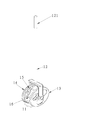
図1は、本発明のボール回収装置に係る実施態様図である。この図において、ボール回収装置は筒体11と制御部材12とを含める。筒体11の両端にはそれぞれ第1蓋体13と第2蓋体14とを設け、第1蓋体13と第2蓋体14により、筒体11内部にて収容空間を形成する。第2蓋体14は少なくとも一つの弾性部材15を環設し、かつ第1蓋体13と第2蓋体14は中空状で、筒体11の胴部も中空状の様態となり、桿体16によって連結される。制御部材12は筒体11に連結し、制御部材12は第1延設体(図示しない)、第2延設体(図示しない)と、握持部121とを設ける。第1延設体は第1蓋体13に枢接し、第2延設体は第2蓋体14に枢接し、握持部121は使用者の握持に供する。これによって、使用者は制御部材を押して筒体を転がすことができる。
FIG. 1 is an embodiment of the ball collecting apparatus according to the present invention. In this figure, the ball collection device includes a
また、桿体16は金属、硬質プラスチックまたはアクリル部材のいずれかの一つであっても良い。弾性部材15はプラスチックシート、ゴムシート、スポンジ体、ばねまたはその他弾性を持つ部件のいずれかの一つであり、かつ弾性部材15はシート状弾性部材または環状弾性体のいずれかの一つであっても良い。第1蓋体13はさらに開閉部を含め、この開閉部は第1蓋体13が筒体11の一端に開放又は閉合状態を制御する。第2蓋体14はさらに開閉部を含め、この開閉部は第2蓋体14が筒体11の一端の開放又は閉合状態を制御する。
Further, the
そのほか、第1蓋体13はさらに複数の第1穴を有する第1制御板と、複数の第2穴を有する第2制御板とを含め、少なくとも一つのボールを対応する第2穴と第1穴から取り出せるように、第2制御板は第2穴を第1制御板の第1穴に対応し制御する。第2蓋体14はさらに複数の第1穴を有する第1制御板と、複数の第2穴を有する第2制御板とを含め、少なくとも一つのボールを対応する第2穴と第1穴から取り出せるように、第2制御板は第2穴を第1穴に対応し制御する。
In addition, the
図2および図3を併せて参照する。図2は、本発明のボール回収装置の好ましい実施例に係る部品分解図であり、図3は、本発明のボール回収装置の好ましい実施例に係る部品組合せ図である。図2において、ボール回収装置は筒体11と制御部材12とを含める。そのうち、筒体11の両端にはそれぞれ第1蓋体13と第2蓋体14とを設け、筒体11内部に収容空間を形成し、筒体11の胴部は中空状で、間隔をおきに少なくとも一つの環状体17に連結し、第2蓋体14と各環状体17は少なくとも一つの弾性部材15を設け、第1蓋体13、第2蓋体14と各環状体17の間には、少なくとも一つの桿体16によって連結される。筒体11は円柱体を形成し、接触面の摩擦力を軽減し、使用者は制御部材12の握持部121を握持し、円柱体の筒体11を推し進みながら筒体11をすばやく転がせて、省力の実用効果を実現できる。
Please refer to FIG. 2 and FIG. 3 together. FIG. 2 is an exploded view of parts according to a preferred embodiment of the ball collection apparatus of the present invention, and FIG. 3 is a combination diagram of parts according to a preferred embodiment of the ball collection apparatus of the present invention. In FIG. 2, the ball collection device includes a
床に散らばったボール20を回収しようとするときは、制御部材12の握持部121を握持し、筒体11を推し進みながら、筒体11を転がせる。筒体11の胴部は中空状で、かつ間隔をおきに桿体16に連結する。そのうち、環状体17の間隔は、ボール20直径より少なめに大きく設けて、これらの環状体17の間隔は、ボール20の収容空間を進入に提供する。桿体16は金属、硬質プラスチックまたはアクリル部材のいずれかの一つであっても良い。
When collecting the
第2蓋体14および各環状体17は、少なくとも一つの弾性部材15を環設し、弾性部材15はプラスチックシート、ゴムシート、スポンジ体、ばねまたはその他弾性部件のいずれかの一つであり、かつ弾性部材15はシート状弾性部材または環状弾性体のいずれかの一つであっても良い。これによって、もし弾性部材がシート状弾性部材の場合、複数のシート状弾性部材を環状体17に環設する。一方、もし弾性部材が環状弾性体の場合、環状弾性体を環状体17に設ける。それに、弾性部材15は環状体17の片側に設けるか、または環状体17の両側に設けることができる。弾性部材15は、これらのボール20を押し圧力で偏移移動させて収容空間に入り込む。されに、これらのボール20によりこれらの弾性部材15を抑圧して収容空間に押し込んで集積し、ボール回収の利便性を実現する。
The
そのほか、第1蓋体13は筒体11と一体化に成形し、第1蓋体13を筒体11の閉合端とする。第2蓋体14はさらに開閉部(図示しない)を含め、この開閉部は第2蓋体14が筒体11の一端に開放又は閉合状態を制御する。そのうち、開閉部はねじ山を有する回転部またはプッシュ式可動部材であり、いずれかの開閉部とも第2蓋体14に対応できる。ボール20を収容空間に集積された後、使用者は開閉部を操作し第2蓋体14を開けて、これらのボール20をバスケットまたはその他の収納具に収納し、これによって、使用者が繰り返し練習を再開でき、使用の利便性を実現できる。
In addition, the
図4は、本発明のボール回収装置もう一つの実施例に係る実施態様図である。この図において、ボール回収装置は筒体11と制御部材12とを含める。筒体11の両端にはそれぞれ第1蓋体13と第2蓋体14に連結し、筒体11内部に収容空間を形成し、筒体11の胴部は中空状で、かつ間隔をおきに複数の環状体17を設け、各環状体17は少なくとも一つの弾性部材15と一つの桿体26とを連結する。制御部材12は筒体11に連結し、制御部材12は使用者が握持部121を握持しながら、筒体11を推し進み転がせる。環状体17の間隔は、ボール20が収容空間を通過し進入するようにできるようにこれらの環状体17の間隔は、ボール20直径より少なめに大きく設けている。これに、環状体17は金属、硬質プラスチックまたはアクリル部材のいずれかの一つであっても良い。これらの環状体17は少なくとも一つの弾性部材15と少なくとも一つの桿体26とを連結する。これらのボール20によりこれらの弾性部材15を抑圧して収容空間に押し込んで集積し、これらの桿体26はこれらの環状体17の支承に提供し、およびこれらの環状体17と第1蓋体13と第2蓋体14との支承にも提供する。これにより、本発明に係る装置はボール回収の利便性を実現できる。
FIG. 4 is an embodiment diagram according to another embodiment of the ball collecting apparatus of the present invention. In this figure, the ball collection device includes a
なお、発明を実施例するための最良の形態の項において具体的な実施例は、あくまでも本発明の技術内容を明らかにするものであって、そのような具体例にのみ限定して狭義に解釈されるべきものではない。本発明の精神および添付の特許請求の範囲内で変更して実施することができる。 It should be noted that the specific examples in the section of the best mode for carrying out the invention are intended to clarify the technical contents of the present invention, and are limited to such specific examples and interpreted in a narrow sense. Should not be done. Modifications can be made within the spirit of the invention and the scope of the appended claims.
11 筒体
12 制御部材
121 握持部
13 第1蓋体
14 第2蓋体
15 弾性部材
16 桿体
17 環状体
20 ボール
26 桿体
DESCRIPTION OF
Claims (20)
両端にはそれぞれ第1蓋体と第2蓋体とを設け、内部に収容空間を形成し、胴部は中空状で、かつ間隔をおきに少なくとも一つの環状体を設ける筒体と、
前記筒体に連結する制御部材と、
を備え
各前記環状体は、少なくとも一つの弾性部材を設け、前記第1蓋体、前記第2蓋体及び当該環状体は少なくとも一つの桿体によって連結されるを特徴とする、ボール回収装置。 In the ball collection device,
A cylindrical body in which a first lid and a second lid are provided at both ends, a housing space is formed therein, a body is hollow, and at least one annular body is provided at intervals.
A control member coupled to the cylinder;
Each of the annular bodies is provided with at least one elastic member, and the first lid body, the second lid body, and the annular body are connected by at least one housing.
複数の第1穴を有する第1制御板と、
複数の第2穴を有する第2制御板と、
を含め、
前記第2制御板は、当該第2穴が対応する第1制御板の当該第1穴を制御し、少なくとも一つのボールを対応の当該第2穴と当該第1穴から取り出せることを特徴とする、請求項1記載のボール回収装置。 The first lid further includes a first control plate having a plurality of first holes;
A second control plate having a plurality of second holes;
Including
The second control plate controls the first hole of the first control plate to which the second hole corresponds, and can take out at least one ball from the corresponding second hole and the first hole. The ball recovery device according to claim 1.
複数の第1穴を有する第1制御板と、
複数の第2穴を有する第2制御板と、
を含め、
前記第2制御板は、当該第2穴が対応する第1制御板の当該第1穴を制御し、少なくとも一つのボールを対応の当該第2穴と当該第1穴から取り出せることを特徴とする、請求項1記載のボール回収装置。 The second lid further includes a first control plate having a plurality of first holes,
A second control plate having a plurality of second holes;
Including
The second control plate controls the first hole of the first control plate to which the second hole corresponds, and can take out at least one ball from the corresponding second hole and the first hole. The ball recovery device according to claim 1.
The ball collecting apparatus according to claim 1, wherein the control member further includes a gripping portion.
両端には第1蓋体と第2蓋体とを連結し、内部に収容空間を形成する筒体と、
前記筒体に連結する制御部材と、
を備え、
前記第2蓋体は、少なくとも一つの弾性部材を環設し、前記第1蓋体と前記第2蓋体とは中空状で、少なくとも一つの桿体によって連結されることを特徴とする、ボール回収装置。 In the ball collection device,
A cylinder that connects the first lid and the second lid to both ends and forms an accommodation space therein,
A control member coupled to the cylinder;
With
The second lid includes at least one elastic member, and the first lid and the second lid are hollow and connected by at least one housing. Recovery device.
複数の第1穴を有する第1制御板と、
複数の第2穴を有する第2制御板と、
を含め、
前記第2制御板は、当該第2穴が対応する第1制御板の当該第1穴を制御し、少なくとも一つのボールを対応の当該第2穴と、当該第1穴から取り出せることを特徴とする、請求項11記載のボール回収装置。 The first lid further includes a first control plate having a plurality of first holes;
A second control plate having a plurality of second holes;
Including
The second control plate controls the first hole of the first control plate to which the second hole corresponds, and can take out at least one ball from the corresponding second hole and the first hole. The ball collecting apparatus according to claim 11.
複数の第1穴を有する第1制御板と、
複数の第2穴を有する第2制御板と、
を含め、
前記第2制御板は、当該第2穴が対応する第1制御板の当該第1穴を制御し、少なくとも一つのボールを対応の当該第2穴と当該第1穴から取り出せることを特徴とする、請求項11記載のボール回収装置。 The second lid further includes a first control plate having a plurality of first holes,
A second control plate having a plurality of second holes;
Including
The second control plate controls the first hole of the first control plate to which the second hole corresponds, and can take out at least one ball from the corresponding second hole and the first hole. The ball collecting apparatus according to claim 11.
12. The ball collecting apparatus according to claim 11, wherein the second lid body is provided with at least one elastic member.
Applications Claiming Priority (4)
| Application Number | Priority Date | Filing Date | Title |
|---|---|---|---|
| TW097126856 | 2008-07-15 | ||
| TW97126856 | 2008-07-15 | ||
| TW098120308 | 2009-06-17 | ||
| TW098120308A TW201019992A (en) | 2008-07-15 | 2009-06-17 | Ball-receiving apparatus |
Publications (2)
| Publication Number | Publication Date |
|---|---|
| JP2010022824A true JP2010022824A (en) | 2010-02-04 |
| JP5306085B2 JP5306085B2 (en) | 2013-10-02 |
Family
ID=41170064
Family Applications (1)
| Application Number | Title | Priority Date | Filing Date |
|---|---|---|---|
| JP2009164112A Active JP5306085B2 (en) | 2008-07-15 | 2009-07-10 | Ball collection device |
Country Status (6)
| Country | Link |
|---|---|
| US (1) | US8132836B2 (en) |
| EP (1) | EP2145655B1 (en) |
| JP (1) | JP5306085B2 (en) |
| KR (1) | KR101201983B1 (en) |
| AT (1) | ATE523227T1 (en) |
| TW (1) | TW201019992A (en) |
Cited By (1)
| Publication number | Priority date | Publication date | Assignee | Title |
|---|---|---|---|---|
| JP2017119071A (en) * | 2015-12-31 | 2017-07-06 | 遠東科技大学Far East University | Ball collecting device with ball collection module |
Families Citing this family (11)
| Publication number | Priority date | Publication date | Assignee | Title |
|---|---|---|---|---|
| US20090023523A1 (en) * | 2007-07-20 | 2009-01-22 | Gary Poillucci | Apparatus and method for collecting projectile game pieces |
| WO2016020075A1 (en) * | 2014-08-02 | 2016-02-11 | Husqvarna Ab | Fruit collector, retaining bracket and collecting container |
| TWI564057B (en) * | 2015-12-31 | 2017-01-01 | 遠東科技大學 | Driven type ball collecting device |
| TWI564056B (en) * | 2015-12-31 | 2017-01-01 | 遠東科技大學 | Side-handle type ball collecting device |
| US9764202B2 (en) * | 2015-12-31 | 2017-09-19 | Far East University | Ball collecting device with ball collecting module |
| US10589152B2 (en) | 2016-03-18 | 2020-03-17 | Sure Win, Llc | Apparatus for collecting and storing tennis balls |
| KR101870124B1 (en) * | 2017-04-26 | 2018-06-25 | 주식회사 더 테니스 | Collecting device for ball |
| CN108568067B (en) * | 2018-06-28 | 2024-01-30 | 重庆宇爵智能科技有限公司 | Ball sweeping vehicle and ball sweeping mechanism thereof |
| JP7297508B2 (en) * | 2019-04-19 | 2023-06-26 | 株式会社やまびこ | Ball recovery wheel and ball recovery machine |
| JP7192084B1 (en) | 2021-12-15 | 2022-12-19 | 東芝エレベータ株式会社 | Elevator control device and elevator control method |
| USD1017351S1 (en) * | 2023-07-26 | 2024-03-12 | Shijia Jiang | Nut gatherer |
Citations (6)
| Publication number | Priority date | Publication date | Assignee | Title |
|---|---|---|---|---|
| JPS4885747U (en) * | 1971-12-02 | 1973-10-18 | ||
| JPS535059U (en) * | 1976-06-28 | 1978-01-18 | ||
| US4991896A (en) | 1989-04-17 | 1991-02-12 | Martin E Ralph | Golf ball retriever |
| US5152565A (en) * | 1991-06-03 | 1992-10-06 | Dodd Samuel E | Golf ball retriever |
| JPH0780101A (en) * | 1993-09-14 | 1995-03-28 | Kanagawa Kurorera Kk | Ball collecting device |
| US5407242A (en) * | 1994-05-09 | 1995-04-18 | Beranek; Kurt G. | Tennis ball retriever |
Family Cites Families (9)
| Publication number | Priority date | Publication date | Assignee | Title |
|---|---|---|---|---|
| US3306480A (en) * | 1964-11-19 | 1967-02-28 | Harvey G Wysong | Golf ball retriever |
| US4077194A (en) * | 1976-04-27 | 1978-03-07 | Livingston Almer K | Apparatus for collecting objects from a surface |
| US4593519A (en) * | 1983-09-22 | 1986-06-10 | Kimball Jerome W | Apparatus for picking up objects randomly distributed on a surface |
| US4645254A (en) * | 1986-04-07 | 1987-02-24 | Warden Roland R | Portable golf ball retriever |
| US6422621B1 (en) * | 2001-05-16 | 2002-07-23 | Steven Tandlich | Tennis ball retrieving and storing system |
| US20050168051A1 (en) * | 2004-02-02 | 2005-08-04 | Kuan Hsings Enterprise Corp. | Rotating hubcap |
| US7341294B2 (en) * | 2004-10-15 | 2008-03-11 | Thomas Wilson Olmstead | Tennis ball retrieval cart and practice hopper |
| TWM284412U (en) | 2005-10-05 | 2006-01-01 | Mei-Hua Chen | Structure of drum type ball pick-up device |
| US7462010B1 (en) * | 2006-02-28 | 2008-12-09 | Wittek Golf Supply Company Inc. | Golf ball collection apparatus with reversal protection |
-
2009
- 2009-06-17 TW TW098120308A patent/TW201019992A/en not_active IP Right Cessation
- 2009-07-10 JP JP2009164112A patent/JP5306085B2/en active Active
- 2009-07-13 AT AT09165290T patent/ATE523227T1/en not_active IP Right Cessation
- 2009-07-13 US US12/502,203 patent/US8132836B2/en not_active Expired - Fee Related
- 2009-07-13 EP EP09165290A patent/EP2145655B1/en not_active Not-in-force
- 2009-07-14 KR KR1020090063952A patent/KR101201983B1/en active IP Right Grant
Patent Citations (6)
| Publication number | Priority date | Publication date | Assignee | Title |
|---|---|---|---|---|
| JPS4885747U (en) * | 1971-12-02 | 1973-10-18 | ||
| JPS535059U (en) * | 1976-06-28 | 1978-01-18 | ||
| US4991896A (en) | 1989-04-17 | 1991-02-12 | Martin E Ralph | Golf ball retriever |
| US5152565A (en) * | 1991-06-03 | 1992-10-06 | Dodd Samuel E | Golf ball retriever |
| JPH0780101A (en) * | 1993-09-14 | 1995-03-28 | Kanagawa Kurorera Kk | Ball collecting device |
| US5407242A (en) * | 1994-05-09 | 1995-04-18 | Beranek; Kurt G. | Tennis ball retriever |
Cited By (1)
| Publication number | Priority date | Publication date | Assignee | Title |
|---|---|---|---|---|
| JP2017119071A (en) * | 2015-12-31 | 2017-07-06 | 遠東科技大学Far East University | Ball collecting device with ball collection module |
Also Published As
| Publication number | Publication date |
|---|---|
| TWI372640B (en) | 2012-09-21 |
| EP2145655B1 (en) | 2011-09-07 |
| US8132836B2 (en) | 2012-03-13 |
| JP5306085B2 (en) | 2013-10-02 |
| KR20100008347A (en) | 2010-01-25 |
| EP2145655A1 (en) | 2010-01-20 |
| ATE523227T1 (en) | 2011-09-15 |
| US20100016102A1 (en) | 2010-01-21 |
| KR101201983B1 (en) | 2012-11-15 |
| TW201019992A (en) | 2010-06-01 |
Similar Documents
| Publication | Publication Date | Title |
|---|---|---|
| JP5306085B2 (en) | Ball collection device | |
| US20090176623A1 (en) | Adductor Exerciser | |
| US6364816B1 (en) | Arm-building device | |
| CN100585083C (en) | Portable animal dejection collecting equipment | |
| KR20180112605A (en) | Apparatus for ball retrieving | |
| JP3156657U (en) | Table tennis ball collection tool | |
| JP3210988U (en) | Exercise equipment | |
| KR100964156B1 (en) | Ball Gleaning Breath | |
| CN212308801U (en) | Sports apparatus hand rehabilitation training device | |
| CN201348774Y (en) | Vertical type mouse | |
| CN106730737A (en) | Integral type body-building horse riding machine | |
| CN206613109U (en) | Autism children muscle trainer | |
| CN208582928U (en) | A kind of leg massor | |
| KR200450240Y1 (en) | Tennis ball collector | |
| KR100911668B1 (en) | Multifunctional motion machinery | |
| CN113041131B (en) | Traditional chinese medical science is with supplementary back massage hammer | |
| CN211724502U (en) | Multifunctional fitness equipment | |
| CN216222805U (en) | Department of neurology rehabilitation auxiliary device | |
| CN211245368U (en) | Portable intelligent body-building equipment | |
| CN216647830U (en) | Support frame for drum set exercise pad frame | |
| CN209865142U (en) | Portable pull-up | |
| CN201949559U (en) | Assembled waist and abdomen fitness device | |
| KR20110010065U (en) | Pingpong ball collecting device | |
| CN211584139U (en) | Multifunctional walking aid for rehabilitation | |
| CN211498686U (en) | Portable pet excrement collecting and cleaning device |
Legal Events
| Date | Code | Title | Description |
|---|---|---|---|
| A131 | Notification of reasons for refusal |
Free format text: JAPANESE INTERMEDIATE CODE: A131 Effective date: 20110921 |
|
| A977 | Report on retrieval |
Free format text: JAPANESE INTERMEDIATE CODE: A971007 Effective date: 20110922 |
|
| A521 | Request for written amendment filed |
Free format text: JAPANESE INTERMEDIATE CODE: A523 Effective date: 20111219 |
|
| A02 | Decision of refusal |
Free format text: JAPANESE INTERMEDIATE CODE: A02 Effective date: 20120314 |
|
| A521 | Request for written amendment filed |
Free format text: JAPANESE INTERMEDIATE CODE: A523 Effective date: 20120709 |
|
| A911 | Transfer to examiner for re-examination before appeal (zenchi) |
Free format text: JAPANESE INTERMEDIATE CODE: A911 Effective date: 20120828 |
|
| A912 | Re-examination (zenchi) completed and case transferred to appeal board |
Free format text: JAPANESE INTERMEDIATE CODE: A912 Effective date: 20121005 |
|
| A521 | Request for written amendment filed |
Free format text: JAPANESE INTERMEDIATE CODE: A821 Effective date: 20130125 |
|
| A521 | Request for written amendment filed |
Free format text: JAPANESE INTERMEDIATE CODE: A523 Effective date: 20130530 |
|
| A61 | First payment of annual fees (during grant procedure) |
Free format text: JAPANESE INTERMEDIATE CODE: A61 Effective date: 20130625 |
|
| R150 | Certificate of patent or registration of utility model |
Free format text: JAPANESE INTERMEDIATE CODE: R150 Ref document number: 5306085 Country of ref document: JP Free format text: JAPANESE INTERMEDIATE CODE: R150 |
|
| R250 | Receipt of annual fees |
Free format text: JAPANESE INTERMEDIATE CODE: R250 |
|
| R250 | Receipt of annual fees |
Free format text: JAPANESE INTERMEDIATE CODE: R250 |
|
| R250 | Receipt of annual fees |
Free format text: JAPANESE INTERMEDIATE CODE: R250 |
|
| R250 | Receipt of annual fees |
Free format text: JAPANESE INTERMEDIATE CODE: R250 |
|
| R250 | Receipt of annual fees |
Free format text: JAPANESE INTERMEDIATE CODE: R250 |
|
| R250 | Receipt of annual fees |
Free format text: JAPANESE INTERMEDIATE CODE: R250 |
|
| R250 | Receipt of annual fees |
Free format text: JAPANESE INTERMEDIATE CODE: R250 |
|
| R250 | Receipt of annual fees |
Free format text: JAPANESE INTERMEDIATE CODE: R250 |