JP2010021114A - Direct oxidation type fuel cell - Google Patents
Direct oxidation type fuel cell Download PDFInfo
- Publication number
- JP2010021114A JP2010021114A JP2008183011A JP2008183011A JP2010021114A JP 2010021114 A JP2010021114 A JP 2010021114A JP 2008183011 A JP2008183011 A JP 2008183011A JP 2008183011 A JP2008183011 A JP 2008183011A JP 2010021114 A JP2010021114 A JP 2010021114A
- Authority
- JP
- Japan
- Prior art keywords
- anode
- fuel
- base material
- layer
- water repellent
- Prior art date
- Legal status (The legal status is an assumption and is not a legal conclusion. Google has not performed a legal analysis and makes no representation as to the accuracy of the status listed.)
- Granted
Links
Images


Classifications
-
- H—ELECTRICITY
- H01—ELECTRIC ELEMENTS
- H01M—PROCESSES OR MEANS, e.g. BATTERIES, FOR THE DIRECT CONVERSION OF CHEMICAL ENERGY INTO ELECTRICAL ENERGY
- H01M8/00—Fuel cells; Manufacture thereof
- H01M8/10—Fuel cells with solid electrolytes
- H01M8/1004—Fuel cells with solid electrolytes characterised by membrane-electrode assemblies [MEA]
-
- H—ELECTRICITY
- H01—ELECTRIC ELEMENTS
- H01M—PROCESSES OR MEANS, e.g. BATTERIES, FOR THE DIRECT CONVERSION OF CHEMICAL ENERGY INTO ELECTRICAL ENERGY
- H01M4/00—Electrodes
- H01M4/86—Inert electrodes with catalytic activity, e.g. for fuel cells
- H01M4/8605—Porous electrodes
- H01M4/861—Porous electrodes with a gradient in the porosity
-
- H—ELECTRICITY
- H01—ELECTRIC ELEMENTS
- H01M—PROCESSES OR MEANS, e.g. BATTERIES, FOR THE DIRECT CONVERSION OF CHEMICAL ENERGY INTO ELECTRICAL ENERGY
- H01M8/00—Fuel cells; Manufacture thereof
- H01M8/02—Details
- H01M8/0202—Collectors; Separators, e.g. bipolar separators; Interconnectors
- H01M8/023—Porous and characterised by the material
- H01M8/0241—Composites
- H01M8/0245—Composites in the form of layered or coated products
-
- H—ELECTRICITY
- H01—ELECTRIC ELEMENTS
- H01M—PROCESSES OR MEANS, e.g. BATTERIES, FOR THE DIRECT CONVERSION OF CHEMICAL ENERGY INTO ELECTRICAL ENERGY
- H01M8/00—Fuel cells; Manufacture thereof
- H01M8/10—Fuel cells with solid electrolytes
- H01M8/1009—Fuel cells with solid electrolytes with one of the reactants being liquid, solid or liquid-charged
-
- Y—GENERAL TAGGING OF NEW TECHNOLOGICAL DEVELOPMENTS; GENERAL TAGGING OF CROSS-SECTIONAL TECHNOLOGIES SPANNING OVER SEVERAL SECTIONS OF THE IPC; TECHNICAL SUBJECTS COVERED BY FORMER USPC CROSS-REFERENCE ART COLLECTIONS [XRACs] AND DIGESTS
- Y02—TECHNOLOGIES OR APPLICATIONS FOR MITIGATION OR ADAPTATION AGAINST CLIMATE CHANGE
- Y02E—REDUCTION OF GREENHOUSE GAS [GHG] EMISSIONS, RELATED TO ENERGY GENERATION, TRANSMISSION OR DISTRIBUTION
- Y02E60/00—Enabling technologies; Technologies with a potential or indirect contribution to GHG emissions mitigation
- Y02E60/30—Hydrogen technology
- Y02E60/50—Fuel cells
Abstract
Description
本発明は、直接酸化型燃料電池に関し、特にアノード拡散層の構造の改良に関する。 The present invention relates to a direct oxidation fuel cell, and more particularly to improvement of the structure of an anode diffusion layer.
携帯電話、ノートPC、デジタルカメラ等のモバイル機器の高性能化に伴い、その電源として、固体高分子電解質膜を用いた燃料電池の実用化が期待されている。固体高分子型燃料電池(以下、単に「燃料電池」とする)の中でも、メタノールなどの燃料を直接アノードへ供給する直接酸化型燃料電池は、小型軽量化に適しており、モバイル機器用電源として開発が進められている。 As mobile devices such as mobile phones, notebook PCs, and digital cameras become more sophisticated, it is expected that fuel cells using a solid polymer electrolyte membrane as a power source will be put to practical use. Among solid polymer fuel cells (hereinafter simply referred to as “fuel cells”), direct oxidation fuel cells that supply fuel such as methanol directly to the anode are suitable for miniaturization and weight reduction, and as power sources for mobile devices Development is underway.
燃料電池は、膜電極接合体(MEA)を具備する。MEAは、高分子電解質膜と、その両面にそれぞれ接合されたアノード(燃料極)およびカソード(空気極)で構成されている。アノードは、アノード触媒層とアノード拡散層からなり、カソードは、カソード触媒層とカソード拡散層からなる。MEAが一対のセパレータで挟み込まれることで、セルが構成される。アノード側セパレータは、アノードに水素やメタノールなどの燃料を供給する燃料流路を有する。カソード側セパレータは、カソードに酸素や空気などの酸化剤を供給する酸化剤流路を有する。 The fuel cell includes a membrane electrode assembly (MEA). The MEA is composed of a polymer electrolyte membrane, and an anode (fuel electrode) and a cathode (air electrode) bonded to both surfaces thereof. The anode is composed of an anode catalyst layer and an anode diffusion layer, and the cathode is composed of a cathode catalyst layer and a cathode diffusion layer. The MEA is sandwiched between a pair of separators to form a cell. The anode side separator has a fuel flow path for supplying fuel such as hydrogen or methanol to the anode. The cathode side separator has an oxidant channel for supplying an oxidant such as oxygen or air to the cathode.
直接酸化型燃料電池の実用化には、いくつかの課題が存在する。
その1つは、長期寿命特性である。燃料電池は、発電時間を重ねるに従って徐々に出力が低下していく。モバイル機器用電源としては、延べ5000時間以上の出力維持が求められるが、現状ではそこまでの寿命特性を達成できてはいない。
There are several problems in putting a direct oxidation fuel cell into practical use.
One of them is long-term life characteristics. The output of the fuel cell gradually decreases as the power generation time increases. As a power source for mobile devices, output maintenance for a total of 5000 hours or more is required.
出力低下の原因には、いくつかの要因が挙げられる。その1つは、メタノールクロスオーバー(MCO)と呼ばれる現象であり、アノードに供給されたメタノールなどの燃料が電解質膜を透過してカソードまで移動する現象である。MCOは、カソード電位を低下させるため、出力を低下させる。また、電解質膜を透過してカソードに達したメタノールが空気と反応することで、空気を余分に消費するため、空気の下流側で空気不足によって出力が低下する。MCOの量は発電時間を重ねるに従って増加する傾向にあり、寿命特性に影響するとされている。 There are several factors that can cause the output to decrease. One of them is a phenomenon called methanol crossover (MCO), in which a fuel such as methanol supplied to the anode moves through the electrolyte membrane to the cathode. The MCO lowers the output because it lowers the cathode potential. In addition, methanol that has permeated the electrolyte membrane and reached the cathode reacts with air, so that excess air is consumed. Therefore, the output is reduced due to insufficient air on the downstream side of the air. The amount of MCO tends to increase with increasing power generation time, and is considered to affect the life characteristics.
MCOを低減するには、アノード拡散層におけるメタノールの拡散性を低減することが有効と考えられる。しかし、アノード全体に渡ってメタノールの拡散性を低減すると、燃料の下流側でメタノールが不足し、出力の低下が起こる。 In order to reduce the MCO, it is considered effective to reduce the diffusibility of methanol in the anode diffusion layer. However, if the diffusibility of methanol is reduced over the entire anode, methanol is insufficient on the downstream side of the fuel, resulting in a decrease in output.
上記課題を鑑み、アノード拡散層のメタノール透過係数を、燃料の下流側ほど大きくすることが提案されている(特許文献1)。これにより、燃料の上流側でMCOを低減すると同時に、燃料の下流側でメタノールの供給量を確保しようとするものである。具体的には、アノード拡散層が具備する導電性撥水層において、その組成や厚みを、燃料の上流側と下流側とで変化させることが提案されている。導電性撥水層は、導電剤と撥水剤とを含んでいる。
特許文献1は、アノード拡散層が具備する導電性撥水層の組成や厚みを変化させることを提案しているが、このような手段では、十分な効果を得ることはできず、満足のいく長期寿命特性を達成するまでには至っていない。その理由は主に2つあり、導電性撥水層の特徴に由来している。
まず、導電性撥水層は、通常50μm程度の厚みしか有さない。よって、導電性撥水層の組成などを変化させても、メタノールなどの燃料の透過性を大きく変化させることは困難である。特に、燃料濃度が高い場合には、導電性撥水層に対する燃料の透過性は全体的に高くなる。よって、薄い導電性撥水層では、燃料の透過性を変化させる効果が得られにくい。 First, the conductive water repellent layer usually has a thickness of only about 50 μm. Therefore, even if the composition of the conductive water repellent layer is changed, it is difficult to greatly change the permeability of fuel such as methanol. In particular, when the fuel concentration is high, the permeability of the fuel to the conductive water repellent layer is increased as a whole. Therefore, it is difficult to obtain an effect of changing the fuel permeability with a thin conductive water repellent layer.
また、導電性撥水層は、燃料の拡散を制御する役割を有すると同時に、拡散層と触媒層とを接合する役割を有する。導電性撥水層の組成や厚みが大きく変化すると、拡散層と触媒層との接合性が低下しやすくなる。よって、導電性の確保が困難になり、更に、アノード全体における燃料の拡散性を制御することが困難になる。 In addition, the conductive water repellent layer has a role of controlling the diffusion of the fuel and at the same time has a role of joining the diffusion layer and the catalyst layer. When the composition and thickness of the conductive water repellent layer are greatly changed, the bondability between the diffusion layer and the catalyst layer is likely to be lowered. Therefore, it becomes difficult to ensure conductivity, and it becomes difficult to control the diffusibility of fuel in the whole anode.
そこで、本発明は、アノードにおける燃料の拡散性を制御することにより、拡散性の高いメタノールを高濃度で含むメタノール水溶液を用いる場合でも、MCOを低減するとともに、長期寿命特性が向上した直接酸化型燃料電池を提供することを目的の一つとする。 Therefore, the present invention controls the diffusibility of the fuel at the anode, thereby reducing the MCO and improving the long-term life characteristics even when using a methanol aqueous solution containing a high concentration of highly diffusible methanol. One object is to provide a fuel cell.
本発明の燃料電池は、アノード、カソードおよびアノードとカソードとの間に介在する電解質膜を含む膜電極接合体、アノードに燃料を供給する燃料流路を有するアノード側セパレータ、ならびにカソードに酸化剤を供給する酸化剤流路を有するカソード側セパレータ、を具備し、
アノードは、電解質膜側に配置されたアノード触媒層およびアノード側セパレータ側に配置されたアノード拡散層を含み、
アノード拡散層は、アノード触媒層側に配置され、かつ第1導電剤および第1撥水剤を含む導電性撥水層と、アノード側セパレータ側に配置された基材層とを含み、
基材層の空隙率が、燃料の上流側より下流側で高くなっている。
The fuel cell of the present invention includes an anode, a cathode and a membrane electrode assembly including an electrolyte membrane interposed between the anode and the cathode, an anode separator having a fuel flow path for supplying fuel to the anode, and an oxidant on the cathode. A cathode-side separator having an oxidant channel to be supplied;
The anode includes an anode catalyst layer disposed on the electrolyte membrane side and an anode diffusion layer disposed on the anode separator side,
The anode diffusion layer includes a conductive water repellent layer disposed on the anode catalyst layer side and including the first conductive agent and the first water repellent, and a base material layer disposed on the anode side separator side,
The porosity of the base material layer is higher on the downstream side than on the upstream side of the fuel.
基材層は、導電性多孔質材料および第2撥水剤を含み、基材層に含まれる第2撥水剤の含有量が、燃料の上流側より下流側で低くなっていることが好ましい。
あるいは、基材層は、導電性多孔質材料および第2導電剤を含み、基材層に含まれる第2導電剤の含有量が、燃料の上流側より下流側で低くなっていることが好ましい。
基材層の空隙率は、燃料の上流側から下流側に向かって段階的に高くなっていることが好ましい。
導電性撥水層の組成および厚みは、燃料の上流側から下流側にわたって均一であることが好ましい。
導電性撥水層の燃料透過係数は、燃料の上流側から下流側にわたって均一であることが好ましい。
燃料はメタノールであることが好ましく、2mol/L〜8mol/Lのメタノール濃度を有するメタノール水溶液が燃料流路を通過することが好ましい。
基材層の下流側の空隙率は、上流側の空隙率の1.2〜2倍であることが好ましい。
基材層の厚みは、導電性撥水層の厚みの5〜20倍であることが好ましい。
The base material layer preferably contains a conductive porous material and a second water repellent, and the content of the second water repellent contained in the base material layer is preferably lower on the downstream side than on the upstream side of the fuel. .
Alternatively, the base material layer preferably includes a conductive porous material and a second conductive agent, and the content of the second conductive agent contained in the base material layer is preferably lower on the downstream side than on the upstream side of the fuel. .
It is preferable that the porosity of the base material layer increases stepwise from the upstream side to the downstream side of the fuel.
The composition and thickness of the conductive water repellent layer are preferably uniform from the upstream side to the downstream side of the fuel.
The fuel permeability coefficient of the conductive water repellent layer is preferably uniform from the upstream side to the downstream side of the fuel.
The fuel is preferably methanol, and an aqueous methanol solution having a methanol concentration of 2 mol / L to 8 mol / L preferably passes through the fuel flow path.
The porosity on the downstream side of the base material layer is preferably 1.2 to 2 times the porosity on the upstream side.
The thickness of the base material layer is preferably 5 to 20 times the thickness of the conductive water repellent layer.
本発明によれば、燃料の上流側ではMCOを低減でき、燃料の下流側ではメタノールの供給量を確保することができる。MCOに由来する出力の低下と、メタノールの供給量不足に由来する出力の低下とを両方抑制できるため、燃料電池の長期寿命特性が大幅に向上する。 According to the present invention, the MCO can be reduced on the upstream side of the fuel, and the supply amount of methanol can be ensured on the downstream side of the fuel. Since it is possible to suppress both a decrease in the output derived from the MCO and a decrease in the output derived from the shortage of methanol supply, the long-term life characteristics of the fuel cell are greatly improved.
また、導電性撥水層よりも基材層で燃料の拡散性を制御する場合の方が制御が容易である。よって、拡散性の高いメタノールを高濃度で含むメタノール水溶液を用いる場合でも、燃料の上流側と下流側でメタノールの拡散性を制御することができる。高濃度のメタノール水溶液を用いることで、燃料電池システムの小型軽量化が可能となる。 In addition, the control is easier when the diffusibility of the fuel is controlled by the base material layer than by the conductive water repellent layer. Accordingly, even when a methanol aqueous solution containing a high concentration of highly diffusible methanol is used, the diffusibility of methanol can be controlled on the upstream side and downstream side of the fuel. By using a high-concentration aqueous methanol solution, the fuel cell system can be reduced in size and weight.
本発明の燃料電池は、アノード、カソードおよびアノードとカソードとの間に介在する電解質膜を含む膜電極接合体、アノードに燃料を供給する燃料流路を有するアノード側セパレータ、ならびにカソードに酸化剤を供給する酸化剤流路を有するカソード側セパレータ、を具備する。アノードは、電解質膜側に配置されたアノード触媒層およびアノード側セパレータ側に配置されたアノード拡散層を含む。アノード拡散層は、アノード触媒層側に配置され、かつ第1導電剤および第1撥水剤を含む導電性撥水層と、アノード側セパレータ側に配置された基材層とを含む。 The fuel cell of the present invention includes an anode, a cathode and a membrane electrode assembly including an electrolyte membrane interposed between the anode and the cathode, an anode separator having a fuel flow path for supplying fuel to the anode, and an oxidant on the cathode. A cathode-side separator having an oxidant channel to be supplied. The anode includes an anode catalyst layer disposed on the electrolyte membrane side and an anode diffusion layer disposed on the anode side separator side. The anode diffusion layer is disposed on the anode catalyst layer side and includes a conductive water repellent layer including a first conductive agent and a first water repellent, and a base material layer disposed on the anode separator side.
基材層の空隙率は、燃料の上流側より下流側で高くなっている。空隙率が燃料の上流側より下流側で高くなっている状態とは、例えば、基材層の下流側の空隙率が、上流側の空隙率の1.2〜2倍である状態をいう。 The porosity of the base material layer is higher on the downstream side than on the upstream side of the fuel. The state in which the porosity is higher on the downstream side than the upstream side of the fuel means, for example, a state in which the porosity on the downstream side of the base material layer is 1.2 to 2 times the porosity on the upstream side.
MCOを低減して長期寿命特性を向上させるには、アノード拡散層に含まれる基材層の空隙率を制御することが有効である。 In order to reduce the MCO and improve the long-term life characteristics, it is effective to control the porosity of the base material layer included in the anode diffusion layer.
導電性撥水層は、通常50μm程度の厚みを有する。このように薄い導電性撥水層の組成や厚みを変化させても、燃料の拡散性を制御するのは困難である。一方、基材層は、通常200〜300μm程度の厚みを有する。このように十分な厚みを有する基材層の空隙率を変化させることで、燃料の拡散性をより効果的に制御することができる。これにより、燃料の上流側ではMCOを抑制することができ、燃料の下流側ではメタノールの供給量を十分に確保することができる。MCOに由来する出力の低下と、メタノールの供給量不足に由来する出力の低下とを両方抑制できるため、燃料電池の長期寿命特性が向上する。 The conductive water repellent layer usually has a thickness of about 50 μm. Even if the composition and thickness of the thin conductive water repellent layer are changed, it is difficult to control the diffusibility of the fuel. On the other hand, the base material layer usually has a thickness of about 200 to 300 μm. Thus, the diffusibility of fuel can be controlled more effectively by changing the porosity of the base material layer having a sufficient thickness. Thereby, MCO can be suppressed on the upstream side of the fuel, and a sufficient amount of methanol can be secured on the downstream side of the fuel. Since it is possible to suppress both a decrease in output derived from MCO and a decrease in output derived from insufficient supply of methanol, the long-term life characteristics of the fuel cell are improved.
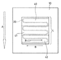
直接酸化型燃料電池について、図面を参照しながら説明する。図1は、直接酸化型燃料電池のセルの構造を概略的に示す縦断面図である。図2は、図1に示す直接酸化型燃料電池の要部拡大図である。直接酸化型燃料電池は、アノード11、カソード12およびアノード11とカソード12との間に介在する電解質膜10を含む膜電極接合体(MEA)13を有する。膜電極接合体13の側面には、ガスケット22および23が配置されている。膜電極接合体13は、アノード側セパレータ14およびカソード側セパレータ15に挟持されている。アノード側セパレータ14は、アノードに燃料を供給する燃料流路20を有する。カソード側セパレータ15は、カソードに酸化剤を供給する酸化剤流路21を有する。
A direct oxidation fuel cell will be described with reference to the drawings. FIG. 1 is a longitudinal sectional view schematically showing the structure of a cell of a direct oxidation fuel cell. FIG. 2 is an enlarged view of a main part of the direct oxidation fuel cell shown in FIG. The direct oxidation fuel cell has a membrane electrode assembly (MEA) 13 including an
アノード11は、電解質膜10側に配置されたアノード触媒層16およびアノード側セパレータ14側に配置されたアノード拡散層17を含む。アノード拡散層17は、アノード触媒層16側に配置される導電性撥水層171と、アノード側セパレータ14側に配置された基材層172とを含む。
カソード12は、電解質膜10側に配置されたカソード触媒層18およびカソード側セパレータ15側に配置されたカソード拡散層19を含む。カソード拡散層19は、カソード触媒層18側に配置される導電性撥水層191と、カソード側セパレータ15側に配置された基材層192とを含む。
The
The
直接酸化型燃料電池は、例えば以下の方法で作製すればよい。アノード11およびカソード12を、電解質膜10を介してホットプレス法などを用いて接合して、膜電極接合体13を作製する。
得られた膜電極接合体13の周側面をガスケット22および23でシールし、アノード側セパレータ14およびカソード側セパレータ15で挟み込む。その後、集電板24および25、ヒータ26および27、絶縁板28および29、ならびに端板30および31で挟み込んで一体化することで、燃料電池1が得られる。
The direct oxidation fuel cell may be manufactured by the following method, for example. The
The peripheral side surface of the obtained
アノード拡散層は、基材層と導電性撥水層とを含む。導電性撥水層は、第1導電剤と、第1撥水剤とを含む。導電性撥水層の組成および厚みは、燃料の上流側から下流側にわたって均一であることが好ましい。これにより、触媒層と拡散層との接合性を確保することができ、導電性の低下などによる出力の低下を抑制することができる。具体的には、上流側の(第1導電剤)/(第1撥水剤)の重量比は、下流側の(第1導電剤)/(第1撥水剤)の重量比の80〜120%であることが好ましい。また、導電性撥水層の燃料の上流側の厚みは、燃料の下流側の厚みの80〜120%であることが好ましい。燃料の上流側の厚みが、燃料の下流側の厚みの80%より小さくなったり、120%を超えると、触媒層と拡散層との接合性が不十分となる場合がある。 The anode diffusion layer includes a base material layer and a conductive water repellent layer. The conductive water repellent layer includes a first conductive agent and a first water repellent. The composition and thickness of the conductive water repellent layer are preferably uniform from the upstream side to the downstream side of the fuel. Thereby, the joining property of a catalyst layer and a diffusion layer can be ensured, and the fall of the output by the electroconductive fall etc. can be suppressed. Specifically, the weight ratio of (first conductive agent) / (first water repellent) on the upstream side is 80 to 80% of the weight ratio of (first conductive agent) / (first water repellent) on the downstream side. 120% is preferable. Further, the thickness of the conductive water repellent layer on the upstream side of the fuel is preferably 80 to 120% of the thickness on the downstream side of the fuel. If the thickness on the upstream side of the fuel is less than 80% or more than 120% of the thickness on the downstream side of the fuel, the bonding property between the catalyst layer and the diffusion layer may be insufficient.
導電性撥水層の組成や厚みを制御することでも、燃料の拡散性を変化させることができる。しかし、上述したように、導電性撥水層は薄いことから、燃料の拡散性を向上させる効果は、基材層の空隙率を制御する場合に比べて小さい。さらに、導電性撥水層の組成や厚みが不均一であると、触媒層と拡散層との接合性が不十分となり、電池特性が低下する場合がある。よって、導電性撥水層の組成および厚みは、燃料の上流側から下流側にわたって均一であることが好ましい。 Controlling the composition and thickness of the conductive water repellent layer can also change the diffusibility of the fuel. However, as described above, since the conductive water-repellent layer is thin, the effect of improving the diffusibility of the fuel is smaller than that in the case of controlling the porosity of the base material layer. Further, if the composition and thickness of the conductive water repellent layer are not uniform, the bonding property between the catalyst layer and the diffusion layer becomes insufficient, and the battery characteristics may be deteriorated. Therefore, the composition and thickness of the conductive water repellent layer are preferably uniform from the upstream side to the downstream side of the fuel.
基材層について説明する。基材層の空隙率は、燃料の上流側より下流側で高くなっている。すなわち、基材層の面方向において、その空隙率が変化している。基材層の空隙率は、燃料の上流から下流にかけて連続的に変化させてもよく、段階的に変化させてもよい。なかでも、基材層の空隙率を段階的に変化させる場合、基材層の製造工程が簡便になり、基材層の空隙率を制御しやすくなる。基材層の空隙率は、例えば2〜10段階に変化させることが好ましく、2〜5段階に変化させることがより好ましい。 The base material layer will be described. The porosity of the base material layer is higher on the downstream side than on the upstream side of the fuel. That is, the porosity changes in the surface direction of the base material layer. The porosity of the base material layer may be changed continuously from upstream to downstream of the fuel, or may be changed stepwise. Especially, when changing the porosity of a base material layer in steps, the manufacturing process of a base material layer becomes simple and it becomes easy to control the porosity of a base material layer. For example, the porosity of the base material layer is preferably changed in 2 to 10 steps, and more preferably in 2 to 5 steps.
燃料の上流側と下流側について、図面を参照しながら説明する。図3は、直接酸化型燃料電池のアノード側セパレータの一例を法線方向から見た上面図である。燃料の流れる方向としては、燃料の入口から燃料の出口へ向かう方向(全体的な流れの方向)と、燃料流路に平行な方向(局所的な流れの方向)とが考えられる。例えば、燃料流路が図3に示すようなサーペンタイン型である場合、燃料流路20の上流側から下流側に向かう全体的な流れの方向(矢印A)と、燃料流路20の局所的な流れの方向(矢印B)とが異なっている。本発明では、燃料の全体的な流れの方向を基準にして、燃料の上流側と下流側とを設定して、基材層の空隙率を変化させることが好ましい。これにより、基材層の製造工程が簡便になり、基材層の空隙率を制御しやすくなる。以下、燃料の全体的な流れの方向を基準にして、燃料の上流側と下流側とを設定して、基材層の空隙率を変化させる場合について説明する。ただし、本発明は、燃料の局所的な流れの方向を基準にして、燃料の上流側と下流側とを設定して、基材層の空隙率を変化させてもよい。
The upstream and downstream sides of the fuel will be described with reference to the drawings. FIG. 3 is a top view of an example of an anode separator of a direct oxidation fuel cell viewed from the normal direction. As the fuel flow direction, a direction from the fuel inlet to the fuel outlet (overall flow direction) and a direction parallel to the fuel flow path (local flow direction) can be considered. For example, when the fuel flow path is a serpentine type as shown in FIG. 3, the overall flow direction (arrow A) from the upstream side to the downstream side of the
アノード拡散層17の上流部40は、燃料流路20の上流側に対向する。燃料流路20の上流側から下流側に向かう全体的な燃料の流れの方向(矢印A)に平行なアノード拡散層17の長さをLとした場合、アノード拡散層17の上流側40の、矢印Aの方向に平行な長さは、L/1.5〜L/5であることが好ましい。
The
アノード拡散層17の下流部42は、燃料流路の下流側に対向する。アノード拡散層17の下流側42の、矢印Aの方向に平行な長さは、L/1.5〜L/5であることが好ましい。
The
上流部と下流部との間には、中流部41があってもよい。中流部41は、空隙率が均一である1つの領域のみであってもよく、空隙率の異なる複数の領域を含んでもよい。中流部が1つの領域のみである場合、上流部、中流部および下流部の空隙率は、燃料の上流側から下流側に向かって段階的に高くなっていることが好ましい。中流部が空隙率の異なる複数の領域を含む場合、上流部、中流部の複数の領域および下流部の空隙率は、燃料の上流側から下流側に向かって段階的に高くなっていることが好ましい。中流部41の、矢印Aの方向に平行な長さは、L/1.5〜L/5であることが好ましい。
There may be a
基材層の空隙率を、燃料の上流側より下流側で高くする方法は特に限定されない。例えば、基材層に第2撥水剤や第2導電剤を含ませて、その含有量を基材層の面方向において変化させる方法、目付け重量が面方向において変化している導電性多孔質材料を用いる方法、面方向において厚みが変化している導電性多孔質材料を、ほぼ均一な厚みまで圧縮して基材層とする方法等が挙げられる。なかでも、基材層に第2撥水剤や第2導電剤を含ませて、その含有量を基材層の面方向において変化させる場合、基材層の製造工程が簡便になり、空隙率を制御しやすくなる。 The method for increasing the porosity of the base material layer on the downstream side from the upstream side of the fuel is not particularly limited. For example, a method in which a second water repellent or a second conductive agent is included in the base material layer and the content is changed in the surface direction of the base material layer, or a conductive porous material whose weight is changed in the surface direction Examples thereof include a method using a material, and a method in which a conductive porous material whose thickness changes in the surface direction is compressed to a substantially uniform thickness to form a base material layer. Especially, when the second water repellent or the second conductive agent is included in the base material layer and the content is changed in the surface direction of the base material layer, the manufacturing process of the base material layer becomes simple and the porosity is increased. It becomes easy to control.
基材層が、導電性多孔質材料および第2撥水剤を含む場合、基材層に含まれる第2撥水剤の含有量を、燃料の上流側より下流側で低くする。これにより、基材層の空隙率を燃料の上流側より下流側で高くすることができるため、燃料の拡散性を効果的に制御することができる。 When the base material layer includes the conductive porous material and the second water repellent, the content of the second water repellent contained in the base material layer is set lower on the downstream side than on the upstream side of the fuel. Thereby, since the porosity of the base material layer can be made higher on the downstream side than on the upstream side of the fuel, the diffusibility of the fuel can be effectively controlled.
基材層全体における第2撥水剤の含有量は、6重量%〜60重量%であることが好ましい。第2撥水剤の含有量が6重量%よりも小さいと、燃料の拡散性を十分に制御できない場合がある。第2撥水剤の含有量が60重量%を超えると、基材層の電子伝導性が低下する場合がある。第2撥水剤の含有量は、基材層の燃料の上流側で30〜65重量%であることが好ましく、下流側で3〜30重量%であることが好ましい。また、基材層全体の空隙率は、40%〜82%であることが好ましく、燃料の上流側の空隙率が35%〜65%であり、下流側の空隙率が70%〜85%であることが好ましい。
空隙率は、まず、基材層の見かけ体積と重量から嵩密度dを求める。嵩密度d、導電性多孔質材料の真密度D1と含有量X1、および第2撥水剤の真密度D2と含有量X2とを用いて、以下の式で空隙率を求めることができる。
式(1):100−d×(X1/D1+X2/D2)
It is preferable that content of the 2nd water repellent in the whole base material layer is 6 to 60 weight%. If the content of the second water repellent is less than 6% by weight, the diffusibility of the fuel may not be sufficiently controlled. If the content of the second water repellent exceeds 60% by weight, the electronic conductivity of the base material layer may be lowered. The content of the second water repellent is preferably 30 to 65% by weight on the upstream side of the fuel of the base material layer, and preferably 3 to 30% by weight on the downstream side. Further, the porosity of the entire base material layer is preferably 40% to 82%, the porosity on the upstream side of the fuel is 35% to 65%, and the porosity on the downstream side is 70% to 85%. Preferably there is.
For the porosity, first, the bulk density d is determined from the apparent volume and weight of the base material layer. Using the bulk density d, the true density D 1 and the content X 1 of the conductive porous material, and the true density D 2 and the content X 2 of the second water repellent, the porosity is obtained by the following formula. Can do.
Equation (1): 100-d × (
第1撥水剤および第2撥水剤は特に限定されず、例えば、燃料電池の分野で常用されるものを特に限定なく用いることができる。具体的には、例えば、フッ素樹脂等を用いることが好ましい。フッ素樹脂は、例えば公知のものを特に限定なく用いることができ、例えば、ポリテトラフルオロエチレン(PTFE)、テトラフルオロエチレン−ヘキサフルオロプロピレン共重合樹脂(FEP)、テトラフルオロエチレン−パーフルオロアルキルビニルエーテル共重合樹脂、テトラフルオロエチレン−エチレン共重合樹脂、ポリフッ化ビニリデンなどが挙げられる。これらの中でも、PTFE、FEPなどが好ましい。第1撥水剤および第2撥水剤は、それぞれ1種のみを単独で用いてもよく、2種以上を組み合わせて用いてもよい。第1撥水剤と第2撥水剤は、同じ撥水剤であってもよく、異なる撥水剤であってもよい。 The first water repellent and the second water repellent are not particularly limited, and for example, those commonly used in the field of fuel cells can be used without particular limitation. Specifically, for example, it is preferable to use a fluororesin or the like. As the fluororesin, for example, known ones can be used without any particular limitation. For example, polytetrafluoroethylene (PTFE), tetrafluoroethylene-hexafluoropropylene copolymer resin (FEP), tetrafluoroethylene-perfluoroalkyl vinyl ether copolymer. Polymerized resin, tetrafluoroethylene-ethylene copolymer resin, polyvinylidene fluoride and the like can be mentioned. Among these, PTFE, FEP and the like are preferable. Each of the first water repellent and the second water repellent may be used alone or in combination of two or more. The first water repellent and the second water repellent may be the same water repellent or different water repellents.
基材層に第2撥水剤を含ませるには、例えば、分散媒に第2撥水剤を分散させたディスパージョンを、導電性多孔質材料に含浸させる。その後、乾燥させて分散媒を除去すればよい。分散媒としては、水やアルコールなどが挙げられる。この場合、燃料の上流側より下流側で第2撥水剤の含有量を低くするには、第2撥水剤を含浸させる条件を、燃料の上流側から下流側にかけて段階的または連続的に変化させればよい。 In order to include the second water repellent in the base material layer, for example, a conductive porous material is impregnated with a dispersion in which the second water repellent is dispersed in a dispersion medium. Thereafter, the dispersion medium may be removed by drying. Examples of the dispersion medium include water and alcohol. In this case, in order to reduce the content of the second water repellent on the downstream side from the upstream side of the fuel, the condition for impregnating the second water repellent is changed stepwise or continuously from the upstream side to the downstream side of the fuel. Change it.
第2撥水剤を分散させたディスパージョンに導電性多孔質材料を浸漬する場合、例えば、導電性多孔質材料を、燃料の上流部および下流部の2つの領域に分ける。その後、塗布する領域以外にマスキングを施す。次に、マスキングされていない領域に、ディスパージョンを塗布する。この方法により、第2撥水剤を含浸させる条件を、段階的に変化させることができる。 When the conductive porous material is immersed in the dispersion in which the second water repellent is dispersed, for example, the conductive porous material is divided into two regions, an upstream portion and a downstream portion of the fuel. Thereafter, masking is applied to areas other than the area to be applied. Next, a dispersion is applied to an unmasked area. By this method, the conditions for impregnating the second water repellent can be changed stepwise.
具体的には、下流部をマスキングした導電性多孔質材料を撥水剤ディスパージョンに浸漬させて、上流部に第2撥水剤を含ませる。その後、上流部をマスキングして、上流部に浸漬させたものとは濃度が異なる撥水剤ディスパージョンに順次浸漬させる。その後、乾燥させることで、第2撥水剤の含有量を制御することができる。ここでは、導電性多孔質材料を2つの領域に分けた場合について説明したが、例えば、燃料の上流部、中流部および下流部の3つの領域に分けてもよい。さらに、導電性多孔質材料を4つ以上の領域に分けてもよい。この場合、上流部から下流部に向かって段階的に第2撥水剤の含有量を低下させる。 Specifically, the conductive porous material whose downstream portion is masked is immersed in a water repellent dispersion, and the second water repellent is included in the upstream portion. Thereafter, the upstream portion is masked and sequentially immersed in a water repellent dispersion having a concentration different from that of the upstream portion. Thereafter, the content of the second water repellent can be controlled by drying. Here, the case where the conductive porous material is divided into two regions has been described. However, for example, the conductive porous material may be divided into three regions of an upstream portion, a midstream portion, and a downstream portion of the fuel. Further, the conductive porous material may be divided into four or more regions. In this case, the content of the second water repellent is gradually reduced from the upstream portion toward the downstream portion.
他にも、滴下装置やスプレー式塗布装置などを用いて第2撥水剤を基材層に含浸させてもよい。この場合、撥水剤ディスパージョンの濃度や、含浸処理の回数などを、段階的または連続的に変化させればよい。 In addition, the base layer may be impregnated with the second water repellent using a dripping device, a spray coating device, or the like. In this case, the concentration of the water repellent dispersion, the number of impregnation treatments, etc. may be changed stepwise or continuously.
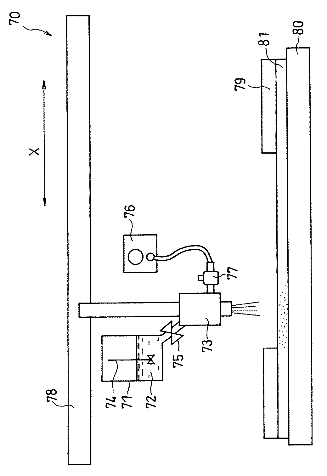
スプレー式塗布装置を用いる場合について、図面を参照しながら説明する。図4は、スプレー式塗布装置の構成を概略的に示す側面図である。 The case of using a spray coating apparatus will be described with reference to the drawings. FIG. 4 is a side view schematically showing the configuration of the spray coating apparatus.
スプレー式塗布装置70は、ディスパージョン72を収容したタンク71およびディスパージョン72を吐出するスプレーガン73を備える。
タンク71内において、ディスパージョン72は、撹拌機74により撹拌されて、常時流動状態にある。ディスパージョン72は、開閉バルブ75を介して、スプレーガン73に供給され、噴出ガスとともに、スプレーガン73から吐出される。噴出ガスは、ガス圧力調整器76およびガス流量調整器77を介して、スプレーガン73に供給される。噴出ガスとしては、例えば、窒素ガスを用いることができる。塗布装置70では、導電性多孔質材料81と接するように配置されたヒータ80により、導電性多孔質材料81の表面温度が制御されている。
The spray-
In the
図4の塗布装置70において、スプレーガン73は、アクチュエータ78により、紙面に垂直な面内において、矢印Xに平行なX軸およびX軸に垂直なY軸の2方向に任意の位置から任意の速度で移動することが可能である。
In the
図4には、導電性多孔質材料81に、第2撥水剤を含ませている様子が示されている。スプレーガン73の下方に導電性多孔質材料81を配置し、スプレーガン73を、ディスパージョン72を吐出させながら移動させることにより、導電性多孔質材料81に第2撥水剤を含ませている。導電性多孔質材料81におけるディスパージョン72の塗布領域は、マスク79を用いて調節することができる。
FIG. 4 shows a state in which the second water repellent agent is included in the conductive
上記のように、塗布装置70においては、スプレーガン73を、任意の位置に移動させながらディスパージョン72を吐出させることができる。つまり、導電性多孔質材料81の任意の位置において、第2撥水剤の量を変化させることができる。よって、塗布装置70を用いることにより、基材層に含まれる第2撥水剤の含有量を、燃料の上流側より下流側で低くすることができる。
As described above, in the
基材層の空隙率は、例えば、ディスパージョンの吐出量、噴出ガスの圧力および流量、基材層の表面温度等を調節することにより、制御することができる。 The porosity of the base material layer can be controlled, for example, by adjusting the discharge amount of the dispersion, the pressure and flow rate of the ejection gas, the surface temperature of the base material layer, and the like.
あるいは、基材層が、導電性多孔質材料および第2導電剤を含む場合、第2導電剤の含有量を、燃料の上流側より下流側で低くする。これにより、電子伝導性の低下を抑制しつつ、基材層の空隙率を燃料の上流側より下流側で高くすることができるため、燃料の拡散性を効果的に制御することができる。 Or when a base material layer contains a conductive porous material and a 2nd electrically conductive agent, content of a 2nd electrically conductive agent is made lower downstream from the upstream of a fuel. Thereby, since the porosity of the base material layer can be increased on the downstream side of the upstream side of the fuel while suppressing the decrease in the electronic conductivity, the diffusibility of the fuel can be effectively controlled.
基材層全体における第2導電剤の含有量は、5〜50重量%であることが好ましい。第2導電剤の含有量が5重量%よりも小さいと、燃料の拡散性を十分に制御できない場合がある。第2導電剤の含有量が50重量%を超えると、基材層全体の空隙率が低くなる場合がある。第2導電剤の含有量は、基材層の燃料の上流側で25重量%〜60重量%であることが好ましく、下流側で0重量%〜20重量%であることが好ましい。 It is preferable that content of the 2nd electrically conductive agent in the whole base material layer is 5 to 50 weight%. If the content of the second conductive agent is less than 5% by weight, the diffusibility of the fuel may not be sufficiently controlled. When the content of the second conductive agent exceeds 50% by weight, the porosity of the entire base material layer may be lowered. The content of the second conductive agent is preferably 25% by weight to 60% by weight on the upstream side of the fuel of the base material layer, and preferably 0% by weight to 20% by weight on the downstream side.
第2導電剤を基材層に含ませる場合、燃料の拡散性をより良好に制御する観点から、さらに第2撥水剤を含ませることが好ましい。このとき、第2撥水剤の含有量は、基材層において均一であってもよく、燃料の上流側より下流側で低くなっていてもよい。 When the second conductive agent is included in the base material layer, it is preferable to further include a second water repellent from the viewpoint of better controlling the diffusibility of the fuel. At this time, the content of the second water repellent may be uniform in the base material layer, or may be lower on the downstream side than on the upstream side of the fuel.
第1導電剤および第2導電剤は、例えば、燃料電池の分野で常用されるものを特に限定なく用いることができる。具体的には、例えば、カーボンブラックや鱗片状黒鉛などの炭素粉末材料、カーボンナノチューブやカーボンナノファイバなどのカーボン繊維などが挙げられる。第2導電剤は、1種のみを単独で用いてもよく、2種以上を組み合わせて用いてもよい。第1導電剤と第2導電剤は、同じ導電剤であってもよく、異なる導電剤であってもよい。 As the first conductive agent and the second conductive agent, for example, those commonly used in the field of fuel cells can be used without particular limitation. Specific examples include carbon powder materials such as carbon black and scaly graphite, and carbon fibers such as carbon nanotubes and carbon nanofibers. The second conductive agent may be used alone or in combination of two or more. The first conductive agent and the second conductive agent may be the same conductive agent or different conductive agents.
基材層に第2導電剤を含ませるには、例えば、第2撥水剤の場合と同様に、第2導電剤の分散液を導電性多孔質材料に含浸させる手段が挙げられる。燃料の上流から下流にかけて第2導電剤の含有量を変化させる手段としては、例えば、第2撥水剤の含有量を変化させる手段として例示したものと同様の手段を、特に限定なく適用することができる。 In order to include the second conductive agent in the base material layer, for example, as in the case of the second water repellent, there is a means for impregnating the conductive porous material with the dispersion liquid of the second conductive agent. As a means for changing the content of the second conductive agent from the upstream to the downstream of the fuel, for example, the same means as exemplified as the means for changing the content of the second water repellent may be applied without any particular limitation. Can do.
あるいは、第2導電剤の前駆体を導電性多孔質材料に含浸させてもよい。その後、不活性雰囲気中で焼成して前駆体を炭化させることで、第2導電剤を含む基材層が得られる。このとき、例えば700℃〜1500℃程度の温度で焼成することが好ましい。不活性雰囲気としては、例えば、N2、Ar、He等が挙げられる。第2導電剤の前駆体としては、例えば、ピッチ類、ポリイミド樹脂、フェノール樹脂などの有機物等が挙げられる。第2導電剤の前駆体は、濃度および粘度を調整するために、有機溶媒を含んでもよい。
第2導電剤の前駆体を含浸させる場合も、燃料の上流から下流にかけて第2導電剤の含有量を変化させる手段は特に限定されない。
Alternatively, the conductive porous material may be impregnated with the precursor of the second conductive agent. Then, the base material layer containing a 2nd electrically conductive agent is obtained by baking in an inert atmosphere and carbonizing a precursor. At this time, it is preferable to bake at a temperature of about 700 ° C. to 1500 ° C., for example. The inert atmosphere, e.g., N 2, Ar, He and the like. Examples of the precursor of the second conductive agent include organic substances such as pitches, polyimide resins, and phenol resins. The precursor of the second conductive agent may include an organic solvent in order to adjust the concentration and viscosity.
Even when impregnating the precursor of the second conductive agent, the means for changing the content of the second conductive agent from the upstream to the downstream of the fuel is not particularly limited.
導電性多孔質材料は、燃料電池の分野で常用される材料を特に限定なく用いることができるが、燃料や酸化剤の拡散性に優れるとともに、高い電子伝導性を有する材料が好ましい。例えば、カーボンペーパー、カーボンクロス、カーボン不織布などの導電性多孔質材料が挙げられる。導電性多孔質材料の厚みは、例えば100μm〜500μmであることが好ましく、200μm〜400μmであることがより好ましい。導電性多孔質材料の厚みは、例えば、導電性撥水層の厚みの5〜20倍である。 As the conductive porous material, a material commonly used in the field of fuel cells can be used without any particular limitation, but a material having excellent electron conductivity and excellent diffusibility of fuel and oxidant is preferable. Examples thereof include conductive porous materials such as carbon paper, carbon cloth, and carbon nonwoven fabric. The thickness of the conductive porous material is preferably, for example, 100 μm to 500 μm, and more preferably 200 μm to 400 μm. The thickness of the conductive porous material is, for example, 5 to 20 times the thickness of the conductive water repellent layer.
導電性撥水層は、第1撥水剤を10重量%〜60重量%含むことが好ましい。導電性撥水層の厚みは、10μm〜80μmであることが好ましく、20〜60μmであることがより好ましい。導電性撥水層の厚みが10μmより小さいと、導電性撥水層と触媒層との接合性が不十分となる場合がある。導電性撥水層の厚みが80μmを超えると、燃料の拡散性が不十分となる場合がある。 The conductive water repellent layer preferably contains 10 wt% to 60 wt% of the first water repellent. The thickness of the conductive water repellent layer is preferably 10 μm to 80 μm, and more preferably 20 to 60 μm. When the thickness of the conductive water repellent layer is less than 10 μm, the bonding property between the conductive water repellent layer and the catalyst layer may be insufficient. When the thickness of the conductive water repellent layer exceeds 80 μm, the fuel diffusibility may be insufficient.
導電性撥水層は、基材層の表面に形成される。導電性撥水層を形成する方法は特に限定されない。例えば、第1導電剤と第1撥水剤を混合、分散させて導電性撥水層ペーストを調製する。導電性撥水層ペーストを、ドクターブレード法やスプレー塗布法によって基材層の片面に塗布し乾燥させることで、導電性撥水層が得られる。 The conductive water repellent layer is formed on the surface of the base material layer. The method for forming the conductive water repellent layer is not particularly limited. For example, a conductive water repellent layer paste is prepared by mixing and dispersing a first conductive agent and a first water repellent. A conductive water-repellent layer is obtained by applying the conductive water-repellent layer paste to one side of the base material layer by a doctor blade method or a spray coating method and drying the paste.
燃料はメタノールであることが好ましく、2mol/L〜8mol/Lのメタノール濃度を有する水溶液として用いることが好ましい。メタノール水溶液のメタノール濃度は、3mol/L〜5mol/Lであることがより好ましい。燃料の濃度が高いほど燃料電池システム全体としての小型軽量化につながるが、MCOが多くなるおそれがある。本発明によれば、MCOを低減することができるため、通常よりもメタノール濃度が高いメタノール水溶液を用いることができる。メタノール濃度が2mol/Lより小さいと、燃料電池システムの小型軽量化が困難となる場合がある。メタノール濃度が8mol/Lを超えると、MCOを十分に低減できない場合がある。上記のメタノール濃度を有する燃料を用いることで、本発明の基材層において、燃料の上流側でMCOを低減しつつ、燃料の下流側でメタノールの供給量をさらに良好に確保することができる。 The fuel is preferably methanol, and is preferably used as an aqueous solution having a methanol concentration of 2 mol / L to 8 mol / L. The methanol concentration of the aqueous methanol solution is more preferably 3 mol / L to 5 mol / L. Higher fuel concentrations lead to smaller and lighter fuel cell systems as a whole, but there is a risk of increased MCO. According to the present invention, since MCO can be reduced, an aqueous methanol solution having a higher methanol concentration than usual can be used. If the methanol concentration is less than 2 mol / L, it may be difficult to reduce the size and weight of the fuel cell system. If the methanol concentration exceeds 8 mol / L, the MCO may not be sufficiently reduced. By using the fuel having the above methanol concentration, in the base material layer of the present invention, it is possible to further ensure the supply amount of methanol on the downstream side of the fuel while reducing the MCO on the upstream side of the fuel.
その他の燃料としては、例えば、エタノール、ジメチルエーテル等が挙げられる。 Examples of other fuels include ethanol and dimethyl ether.
本発明の直接酸化型燃料電池は、上記のアノード拡散層を用いることを特徴とする。それ以外の構成は特に限定されず、例えば従来の燃料電池と同様の構成を用いることができる。カソード拡散層にも、上記と同様の基材層や導電性撥水層を用いることができる。 The direct oxidation fuel cell of the present invention is characterized by using the anode diffusion layer. Other configurations are not particularly limited, and for example, a configuration similar to that of a conventional fuel cell can be used. A substrate layer and a conductive water repellent layer similar to those described above can also be used for the cathode diffusion layer.
電解質膜としては、例えば、従来から用いられているプロトン伝導性高分子膜を特に限定なく使用できる。具体的には、パーフルオロカーボンスルホン酸系高分子膜、炭化水素系高分子膜などを好ましく使用できる。パーフルオロカーボンスルホン酸系高分子膜としては、例えば、Nafion(登録商標)、Flemion(登録商標)等が挙げられる。炭化水素系高分子膜としては、例えばスルホン化ポリエーテルエーテルケトン、スルホン化ポリイミド等が挙げられる。なかでも、炭化水素系高分子膜を用いることで、スルホン酸基のクラスタ構造の形成を抑制し、電解質膜のメタノールの透過性を低減することができる。これにより、MCOをさらに低減することができる。電解質膜の厚みは、20μm〜150μmであることが好ましい。 As the electrolyte membrane, for example, a conventionally used proton conductive polymer membrane can be used without any particular limitation. Specifically, perfluorocarbon sulfonic acid polymer membranes, hydrocarbon polymer membranes and the like can be preferably used. Examples of the perfluorocarbon sulfonic acid polymer membrane include Nafion (registered trademark) and Flemion (registered trademark). Examples of the hydrocarbon polymer membrane include sulfonated polyether ether ketone and sulfonated polyimide. In particular, by using a hydrocarbon polymer membrane, the formation of a cluster structure of sulfonic acid groups can be suppressed, and the methanol permeability of the electrolyte membrane can be reduced. Thereby, MCO can further be reduced. The thickness of the electrolyte membrane is preferably 20 μm to 150 μm.
触媒層は、触媒、担体および高分子電解質を含むことが好ましい。触媒としては、触媒活性の高い貴金属が好ましい。アノード触媒には、一酸化炭素による触媒の被毒を低減する観点から、白金とルテニウムとの合金触媒を用いることが好ましい。カソード触媒には、白金を用いることが好ましい。触媒は担体に担持した形態で用いるのが好ましい。担体としては、電子伝導性や耐酸性の高さから、カーボンブラックなどの炭素材料を用いることが好ましい。高分子電解質としては、プロトン伝導性を有するパーフルオロカーボンスルホン酸系高分子材料を用いることが好ましい。 The catalyst layer preferably contains a catalyst, a carrier, and a polymer electrolyte. As the catalyst, a noble metal having high catalytic activity is preferable. As the anode catalyst, an alloy catalyst of platinum and ruthenium is preferably used from the viewpoint of reducing catalyst poisoning by carbon monoxide. Platinum is preferably used for the cathode catalyst. The catalyst is preferably used in a form supported on a carrier. As the carrier, it is preferable to use a carbon material such as carbon black because of its high electron conductivity and acid resistance. As the polymer electrolyte, it is preferable to use a perfluorocarbon sulfonic acid polymer material having proton conductivity.
触媒層を作製する方法は特に限定されない。例えば、水やアルコールなどを分散媒として触媒層ペーストを調製する。ドクターブレード法やスプレー装置などを用いて、触媒層ペーストをPTFEからなるシート等に塗布することで、触媒層が得られる。 The method for producing the catalyst layer is not particularly limited. For example, a catalyst layer paste is prepared using water or alcohol as a dispersion medium. A catalyst layer is obtained by applying the catalyst layer paste to a sheet of PTFE or the like using a doctor blade method or a spray device.
アノード側セパレータおよびカソード側セパレータも特に限定されない。アノード側セパレータは、アノードに燃料を供給する燃料流路を有する。カソード側セパレータは、カソードに酸化剤を供給する酸化剤流路を有する。燃料流路および酸化剤流路の形状は特に限定されない。例えば、サーペンタイン型、パラレル型等が挙げられる。 The anode side separator and the cathode side separator are not particularly limited. The anode side separator has a fuel flow path for supplying fuel to the anode. The cathode side separator has an oxidant flow path for supplying an oxidant to the cathode. The shapes of the fuel channel and the oxidant channel are not particularly limited. Examples include serpentine type and parallel type.
以下、実施例に基づいて本発明をより具体的に説明するが、本発明は以下の実施例に限定されるものではない。 EXAMPLES Hereinafter, although this invention is demonstrated more concretely based on an Example, this invention is not limited to a following example.
《実施例1》
(a)導電性撥水層ペーストの調製
第1撥水剤と第1導電剤とを、界面活性剤を添加したイオン交換水に分散混合して、導電性撥水層ペーストを調製した。第1撥水剤であるPTFE(ポリテトラフルオロエチレン)を含むPTFEディスパージョン(シグマ アルドリッチ ジャパン(株)製、PTFEの含有量60重量%)を用いた。第1導電剤にはアセチレンブラック(電気化学工業(株)製、デンカブラック)を用いた。アセチレンブラックとPTFEの混合重量比は、50:50となるようにした。
Example 1
(A) Preparation of conductive water-repellent layer paste The first water-repellent agent and the first conductive agent were dispersed and mixed in ion-exchanged water added with a surfactant to prepare a conductive water-repellent layer paste. A PTFE dispersion (Sigma Aldrich Japan Co., Ltd., PTFE content 60% by weight) containing PTFE (polytetrafluoroethylene) as the first water repellent was used. As the first conductive agent, acetylene black (Denka Black, manufactured by Denki Kagaku Kogyo Co., Ltd.) was used. The mixing weight ratio of acetylene black and PTFE was set to 50:50.
(b)基材層の作製
アノード拡散層の基材層を構成する導電性多孔質材料として、カーボンペーパー(東レ(株)製、TGP−H−090、厚み280μm)を用いた。第2撥水剤であるPTFEを含むPTFEディスパージョン(シグマ アルドリッチ ジャパン(株)製)を用いて、基材層の空隙率を3段階で変化させた。
(B) Preparation of base material layer Carbon paper (manufactured by Toray Industries, Inc., TGP-H-090, thickness 280 μm) was used as a conductive porous material constituting the base material layer of the anode diffusion layer. The porosity of the base material layer was changed in three stages using PTFE dispersion (Sigma Aldrich Japan Co., Ltd.) containing PTFE as the second water repellent.
6cm×6cmの基材層を、6cm×2cmの3つの領域に分けた。この領域を、それぞれ燃料の上流部、中流部および下流部とした。上流部および中流部にマスキングを施し、下流部にPTFEの含有量が8重量%であるPTFEディスパージョンを滴下して含浸させ、乾燥させた。 The 6 cm × 6 cm substrate layer was divided into three regions of 6 cm × 2 cm. This region was defined as an upstream portion, a midstream portion, and a downstream portion of the fuel, respectively. Masking was performed on the upstream part and the midstream part, and a PTFE dispersion having a PTFE content of 8% by weight was dropped and impregnated in the downstream part and dried.
次に、上流部および下流部にマスキングを施し、中流部にPTFEの含有量が25重量%であるPTFEディスパージョンを滴下して含浸させ、乾燥させた。次に、中流部および下流部にマスキングを施し、上流部にPTFEの含有量が43重量%であるPTFEディスパージョンを滴下して含浸させ、乾燥させた。いずれも、乾燥温度を350℃として界面活性剤を除去し、第2撥水剤を含む基材層を作製した。第2撥水剤の含有量は、上流部で50重量%であり、中流部で31重量%であり、下流部で11重量%であった。また、基材層の空隙率は、上流部で56%であり、中流部で68%であり、下流部で77%であった。なお、基材層の空隙率は、以下の方法で測定した。まず、上流部、中流部および下流部の3つに切断した基材層、ならびに第2撥水剤を含浸させる前の導電性多孔質材料のそれぞれの重量を測定した。重量と、見かけ体積から、それぞれの嵩密度を求めた。その後、上述の式(1)を用いて、空隙率を求めた。 Next, the upstream portion and the downstream portion were masked, and the PTFE dispersion having a PTFE content of 25% by weight was dropped into the midstream portion to be impregnated and dried. Next, masking was applied to the midstream portion and the downstream portion, and a PTFE dispersion having a PTFE content of 43% by weight was dropped and impregnated into the upstream portion and dried. In all cases, the surfactant was removed at a drying temperature of 350 ° C., and a base material layer containing a second water repellent was prepared. The content of the second water repellent was 50% by weight in the upstream part, 31% by weight in the midstream part, and 11% by weight in the downstream part. Moreover, the porosity of the base material layer was 56% in the upstream portion, 68% in the midstream portion, and 77% in the downstream portion. In addition, the porosity of the base material layer was measured by the following method. First, the weights of the base material layer cut into three parts, the upstream part, the midstream part, and the downstream part, and the conductive porous material before impregnation with the second water repellent were measured. Each bulk density was determined from the weight and the apparent volume. Then, the porosity was calculated | required using the above-mentioned Formula (1).
(c)アノード拡散層およびカソード拡散層の作製
(b)で作製した基材層の片面に、(a)の導電性撥水層ペーストを塗布して、乾燥させ、アノード拡散層を作製した。アノード側の導電性撥水層の厚みは、約40μmであった。
(C) Preparation of anode diffusion layer and cathode diffusion layer The conductive water-repellent layer paste of (a) was applied to one side of the base material layer prepared in (b) and dried to prepare an anode diffusion layer. The thickness of the conductive water repellent layer on the anode side was about 40 μm.
また、基材層の片面に、(b)の導電性撥水層ペーストを塗布して乾燥させ、カソード拡散層を作製した。基材層には、カーボンペーパー(バラードマテリアルプロダクツ社製、AvCarb(登録商標)1071HCB)を用いた。カソード側の導電性撥水層の厚みは、約40μmであった。 Further, the conductive water repellent layer paste (b) was applied on one side of the base material layer and dried to prepare a cathode diffusion layer. For the base material layer, carbon paper (manufactured by Ballard Material Products, AvCarb (registered trademark) 1071HCB) was used. The thickness of the conductive water repellent layer on the cathode side was about 40 μm.
(d)カソード触媒層およびアノード触媒層の作製
ケッチェンブラック(ケッチェンブラックインターナショナル社製、ECP)にPt触媒を担持させたものをカソード用触媒とした。ケッチェンブラックとPtとの重量比は、ケッチェンブラック:Pt=50:50とした。カソード用触媒をイソプロパノール水溶液に分散させた液と、電解質であるナフィオン(登録商標)の分散液(シグマ アルドリッチ ジャパン(株)製、ナフィオン5重量%溶液)とを混合し、カソード触媒層ペーストを作製した。
(D) Preparation of cathode catalyst layer and anode catalyst layer A cathode catalyst was prepared by supporting a Pt catalyst on Ketjen Black (manufactured by Ketjen Black International Co., Ltd., ECP). The weight ratio of ketjen black to Pt was ketjen black: Pt = 50: 50. A cathode catalyst layer paste is prepared by mixing a solution obtained by dispersing a cathode catalyst in an aqueous isopropanol solution and a dispersion of Nafion (registered trademark) electrolyte (manufactured by Sigma Aldrich Japan Co., Ltd., 5% by weight Nafion). did.
また、上記のケッチェンブラックにPtRu合金触媒(原子比Pt:Ru=1:1)を担持させたものをアノード用触媒とした。ケッチェンブラックとPtRu合金との重量比は、ケッチェンブラック:PtRu=50:50とした。アノード用触媒を用いたこと以外、上記と同様にして、アノード触媒層ペーストを調製した。 In addition, a catalyst for PtRu alloy (atomic ratio Pt: Ru = 1: 1) supported on the ketjen black was used as an anode catalyst. The weight ratio of ketjen black to PtRu alloy was ketjen black: PtRu = 50: 50. An anode catalyst layer paste was prepared in the same manner as described above except that the anode catalyst was used.
カソード触媒層ペーストおよびアノード触媒層ペーストを、PTFEシート上に塗布して乾燥させ、カソード触媒層およびアノード触媒層をそれぞれ作製した。カソード触媒層の厚みは約50μmであり、アノード触媒層の厚みは約50μmであった。 The cathode catalyst layer paste and the anode catalyst layer paste were applied on a PTFE sheet and dried to prepare a cathode catalyst layer and an anode catalyst layer, respectively. The thickness of the cathode catalyst layer was about 50 μm, and the thickness of the anode catalyst layer was about 50 μm.
(e)膜電極接合体(MEA)の作製
カソード触媒層とアノード触媒層を電解質膜の両面にホットプレス法によって接合し、PTFEシートを剥離した。さらに、カソード触媒層にカソード拡散層を接合し、アノード触媒層にアノード拡散層を接合した。これにより、膜電極接合体(MEA)を作製した。電解質膜には、ナフィオン(デュポン社製、ナフィオン112)を用いた。
(E) Production of membrane electrode assembly (MEA) The cathode catalyst layer and the anode catalyst layer were bonded to both surfaces of the electrolyte membrane by a hot press method, and the PTFE sheet was peeled off. Further, a cathode diffusion layer was bonded to the cathode catalyst layer, and an anode diffusion layer was bonded to the anode catalyst layer. This produced the membrane electrode assembly (MEA). As the electrolyte membrane, Nafion (Nafion 112, manufactured by DuPont) was used.
(f)燃料電池の作製
MEAの外周部に露出した電解質膜の両面にゴム製ガスケットを配した。その後、アノード側セパレータおよびカソード側セパレータでMEAを挟持した。アノード側セパレータは、アノードに燃料を供給する燃料流路を有する。カソード側セパレータは、カソードに酸化剤を供給する酸化剤流路を有する。アノード側セパレータおよびカソード側セパレータには、いずれもカーボン製のものを用いた。燃料流路および酸化剤流路は、いずれもサーペンタイン型とした。燃料流路の溝幅は1mmであり、深さは1mmであり、長さは150cmであった。酸化剤流路の溝幅は1mmであり、深さは1mmであり、長さは150cmであった。さらに、集電板、ヒータ、絶縁板、端板で順に挟み込むようにして積層し、直接酸化型燃料電池を作製した。
(F) Production of fuel cell Rubber gaskets were disposed on both surfaces of the electrolyte membrane exposed on the outer periphery of the MEA. Thereafter, the MEA was sandwiched between the anode side separator and the cathode side separator. The anode side separator has a fuel flow path for supplying fuel to the anode. The cathode side separator has an oxidant flow path for supplying an oxidant to the cathode. Both the anode side separator and the cathode side separator were made of carbon. Both the fuel channel and the oxidant channel were serpentine types. The groove width of the fuel flow path was 1 mm, the depth was 1 mm, and the length was 150 cm. The groove width of the oxidant channel was 1 mm, the depth was 1 mm, and the length was 150 cm. Further, a direct oxidation fuel cell was fabricated by stacking the current collector plate, the heater, the insulating plate, and the end plate in order.
(g)寿命特性の評価
カソードには空気を供給し、アノードには4mol/Lのメタノール水溶液を供給した。負荷は電子負荷装置により150mA/cm2の定電流とし、60分間の放電を行った。その後30分間休止させた。これを1サイクルとした。燃料電池は60℃に保ち、空気の利用率は50%、燃料の利用率は70%とした。
(G) Evaluation of lifetime characteristics Air was supplied to the cathode, and a 4 mol / L aqueous methanol solution was supplied to the anode. The load was a constant current of 150 mA / cm 2 by an electronic load device, and discharging was performed for 60 minutes. Thereafter, it was rested for 30 minutes. This was one cycle. The fuel cell was kept at 60 ° C., the air utilization rate was 50%, and the fuel utilization rate was 70%.
上記の操作を500サイクル行い、1サイクル目の平均電圧に対する500サイクル目の平均電圧の比率を求めた。結果を表1に示す。 The above operation was performed 500 cycles, and the ratio of the average voltage at the 500th cycle to the average voltage at the first cycle was determined. The results are shown in Table 1.
《実施例2》
基材層の作製において、実施例1で第2撥水剤を含浸させた方法と同様の方法を用いて、第2導電剤を分散させた分散液をカーボンペーパーの3つの領域に含浸させた。分散媒には、界面活性剤を添加したイオン交換水を用い、第2導電剤には、アセチレンブラックを用いた。分散液におけるアセチレンブラックの固形分濃度は、上流部で6重量%とし、中流部で2重量%とした。下流部には、第2導電剤を含浸させなかった。基材層の第2導電剤の含有量は、上流部で38重量%であり、中流部で19重量%であった。
Example 2
In the production of the base material layer, using a method similar to the method of impregnating the second water repellent in Example 1, three regions of carbon paper were impregnated with the dispersion liquid in which the second conductive agent was dispersed. . Ion exchange water added with a surfactant was used as the dispersion medium, and acetylene black was used as the second conductive agent. The solid content concentration of acetylene black in the dispersion was 6 wt% in the upstream portion and 2 wt% in the midstream portion. The downstream portion was not impregnated with the second conductive agent. The content of the second conductive agent in the base material layer was 38% by weight in the upstream part and 19% by weight in the midstream part.
得られた基材層に、第2撥水剤として、8重量%に調製したPTFEディスパージョンを全面に滴下して含浸させ、乾燥させた。基材層全体における第2撥水剤の含有量は、12重量%であった。基材層の空隙率は、上流部で59%であり、中流部で70%であり、下流部で76%であった。 The obtained base layer was impregnated by dripping the entire surface with a PTFE dispersion prepared to 8% by weight as a second water repellent and dried. Content of the 2nd water repellent in the whole base material layer was 12 weight%. The porosity of the base material layer was 59% in the upstream portion, 70% in the midstream portion, and 76% in the downstream portion.
上記で得られた基材層を用いてアノード拡散層を作製したこと以外、実施例1と同様にして、直接酸化型燃料電池を作製した。
作製した燃料電池について、実施例1と同様にして寿命特性の評価を行った。結果を表1に示す。
A direct oxidation fuel cell was produced in the same manner as in Example 1 except that the anode diffusion layer was produced using the substrate layer obtained above.
The life characteristics of the produced fuel cell were evaluated in the same manner as in Example 1. The results are shown in Table 1.
《実施例3》
実施例1と同様にして、アノード拡散層の基材層を作製した。
燃料の上流部、中流部、下流部で、それぞれ組成の異なる導電性撥水層を、以下の方法で基材層に形成した。上流部と中流部にマスキングを施し、下流部にアセチレンブラックとPTFEの混合重量比を70:30とした導電性撥水層ペーストをドクターブレード法により塗布し、乾燥させた。同様にして、中流部にはアセチレンブラックとPTFEの混合重量比を50:50とした導電性撥水層を形成した。上流部にはアセチレンブラックとPTFEの混合重量比を30:70とした導電性撥水層を形成した。それぞれの導電性撥水層の厚みは、いずれも40μmとした。
Example 3
In the same manner as in Example 1, a base material layer for the anode diffusion layer was produced.
Conductive water-repellent layers having different compositions at the upstream, middle and downstream portions of the fuel were formed on the base material layer by the following method. Masking was applied to the upstream part and the middle stream part, and a conductive water-repellent layer paste with a mixing weight ratio of acetylene black and PTFE of 70:30 was applied to the downstream part by the doctor blade method and dried. Similarly, a conductive water repellent layer having a mixing weight ratio of acetylene black and PTFE of 50:50 was formed in the midstream portion. A conductive water repellent layer having a mixing weight ratio of acetylene black and PTFE of 30:70 was formed in the upstream portion. Each conductive water repellent layer had a thickness of 40 μm.
上記で得られたアノード拡散層を用いたこと以外、実施例1と同様にして、直接酸化型燃料電池を作製した。
作製した燃料電池について、実施例1と同様にして寿命特性の評価を行った。結果を表1に示す。
A direct oxidation fuel cell was produced in the same manner as in Example 1 except that the anode diffusion layer obtained above was used.
The life characteristics of the produced fuel cell were evaluated in the same manner as in Example 1. The results are shown in Table 1.
《実施例4》
実施例1と同様にして、直接酸化型燃料電池を作製した。
作製した燃料電池に供給するメタノール水溶液の濃度を1mol/Lとしたこと以外、実施例1と同様にして寿命特性の評価を行った。結果を表1に示す。
Example 4
A direct oxidation fuel cell was produced in the same manner as in Example 1.
Life characteristics were evaluated in the same manner as in Example 1 except that the concentration of the aqueous methanol solution supplied to the produced fuel cell was 1 mol / L. The results are shown in Table 1.
《実施例5》
実施例1と同様にして、直接酸化型燃料電池を作製した。
作製した燃料電池に供給するメタノール水溶液の濃度を8mol/Lとしたこと以外、実施例1と同様にして寿命特性の評価を行った。結果を表1に示す。
Example 5
A direct oxidation fuel cell was produced in the same manner as in Example 1.
Life characteristics were evaluated in the same manner as in Example 1 except that the concentration of the aqueous methanol solution supplied to the produced fuel cell was 8 mol / L. The results are shown in Table 1.
《比較例1》
実施例1のアノード拡散層に用いたものと同様のカーボンペーパー(導電性多孔質材料)の全面に、第2撥水剤であるPTFEを8重量%含むPTFEディスパージョンを滴下して含浸させ、乾燥させた。基材層全体における第2撥水剤の含有量は12重量%であり、基材層の空隙率は77%であった。
<< Comparative Example 1 >>
The entire surface of carbon paper (conductive porous material) similar to that used in the anode diffusion layer of Example 1 was dropped and impregnated with PTFE dispersion containing 8% by weight of PTFE as the second water repellent, Dried. The content of the second water repellent in the entire base material layer was 12% by weight, and the porosity of the base material layer was 77%.
上記で得られた基材層を用いてアノード拡散層を作製したこと以外、実施例1と同様にして、直接酸化型燃料電池を作製した。
作製した燃料電池について、実施例1と同様にして寿命特性の評価を行った。結果を表1に示す。
A direct oxidation fuel cell was produced in the same manner as in Example 1 except that the anode diffusion layer was produced using the substrate layer obtained above.
The life characteristics of the produced fuel cell were evaluated in the same manner as in Example 1. The results are shown in Table 1.
《比較例2》
比較例1と同様の基材層に、実施例3と同様にして導電性撥水層を形成して、アノード拡散層を得た。
<< Comparative Example 2 >>
A conductive water repellent layer was formed on the same base material layer as in Comparative Example 1 in the same manner as in Example 3 to obtain an anode diffusion layer.
上記のアノード拡散層を用いたこと以外、実施例1と同様にして、直接酸化型燃料電池を作製した。
作製した燃料電池について、実施例1と同様にして寿命特性の評価を行った。結果を表1に示す。
A direct oxidation fuel cell was produced in the same manner as in Example 1 except that the anode diffusion layer was used.
The life characteristics of the produced fuel cell were evaluated in the same manner as in Example 1. The results are shown in Table 1.
《比較例3》
比較例2と同様にして、直接酸化型燃料電池を作製した。
作製した燃料電池に供給するメタノール水溶液の濃度を1mol/Lとしたこと以外、実施例1と同様にして寿命特性の評価を行った。結果を表1に示す。
<< Comparative Example 3 >>
A direct oxidation fuel cell was produced in the same manner as in Comparative Example 2.
Life characteristics were evaluated in the same manner as in Example 1 except that the concentration of the aqueous methanol solution supplied to the produced fuel cell was 1 mol / L. The results are shown in Table 1.
アノード拡散層の基材層の空隙率を燃料の上流側より下流側で高くした実施例1〜5の燃料電池は、均一な空隙率の基材層を用いた比較例1の燃料電池より、いずれも寿命特性が大きく向上していた。燃料の上流側においてMCOが低減され、出力の低下が抑制されたことと、燃料の下流側においてメタノールの供給量を十分に確保することができたことから、寿命特性が向上したと考えられる。 The fuel cells of Examples 1 to 5 in which the porosity of the base material layer of the anode diffusion layer was higher on the downstream side than the upstream side of the fuel were compared with the fuel cell of Comparative Example 1 using the base material layer having a uniform porosity, In all cases, the life characteristics were greatly improved. It is considered that the life characteristics were improved because the MCO was reduced on the upstream side of the fuel and the decrease in output was suppressed, and the supply amount of methanol was sufficiently ensured on the downstream side of the fuel.
実施例1および2では、導電性撥水層の組成を、燃料の上流側から下流側に向かって均一にした。一方、実施例3では、導電性撥水層の組成を燃料の上流側から下流側にわたって不均一とした。実施例3の燃料電池よりも、実施例1、2の燃料電池は、寿命特性がさらに向上していた。導電性撥水層の組成を、燃料の上流側から下流側に向かって均一にしたことで、導電性撥水層と触媒層との界面の接合性が良好になり、寿命特性がさらに向上したと考えられる。8mol/Lの高濃度のメタノールを用いた実施例5でも良好な寿命特性が得られており、本発明は、高濃度のメタノールに対しても非常に有効であることが分かる。高濃度のメタノールを用いることで、燃料電池システムをより小型化することができる。 In Examples 1 and 2, the composition of the conductive water repellent layer was made uniform from the upstream side to the downstream side of the fuel. On the other hand, in Example 3, the composition of the conductive water repellent layer was nonuniform from the upstream side to the downstream side of the fuel. The life characteristics of the fuel cells of Examples 1 and 2 were further improved as compared with the fuel cell of Example 3. By making the composition of the conductive water repellent layer uniform from the upstream side to the downstream side of the fuel, the bondability at the interface between the conductive water repellent layer and the catalyst layer is improved, and the life characteristics are further improved. it is conceivable that. Good life characteristics were also obtained in Example 5 using a high concentration of 8 mol / L of methanol, and it can be seen that the present invention is very effective for high concentrations of methanol. By using high-concentration methanol, the fuel cell system can be further downsized.
比較例1では、基材層の空隙率と導電性撥水層の組成とをいずれも均一にした。比較例2、3では、均一な空隙率を有する基材層を用い、導電性撥水層の組成を燃料の上流側と下流側で不均一にした。比較例2および3の燃料電池は、比較例1の燃料電池よりも寿命特性がわずかに改善していた。しかし、比較例2および3の燃料電池は、基材層の空隙率を燃料の上流側より下流側で高くしている実施例1〜5の燃料電池よりも、寿命特性の向上効果が非常に小さかった。導電性撥水層は基材層よりも非常に薄いため、導電性撥水層の組成を燃料の上流側と下流側とで不均一にするだけでは、MCOを低減する効果が十分に得られなかったと考えられる。 In Comparative Example 1, both the porosity of the base material layer and the composition of the conductive water repellent layer were made uniform. In Comparative Examples 2 and 3, a base material layer having a uniform porosity was used, and the composition of the conductive water repellent layer was made non-uniform between the upstream side and the downstream side of the fuel. The life characteristics of the fuel cells of Comparative Examples 2 and 3 were slightly improved as compared with the fuel cell of Comparative Example 1. However, the fuel cells of Comparative Examples 2 and 3 are much more effective in improving the life characteristics than the fuel cells of Examples 1 to 5 in which the porosity of the base material layer is higher on the downstream side than on the upstream side of the fuel. It was small. Since the conductive water-repellent layer is much thinner than the base material layer, the effect of reducing the MCO can be sufficiently obtained simply by making the composition of the conductive water-repellent layer non-uniform between the upstream side and the downstream side of the fuel. Probably not.
燃料のメタノール濃度が高い比較例2の燃料電池は、燃料のメタノール濃度が小さい比較例3よりも寿命特性が低下していた。すなわち、基材層の空隙率を最適化せずに、導電性撥水層を最適化するだけでは、高濃度のメタノールを使用する場合に寿命特性を向上効果が小さいことが確認された。 The fuel cell of Comparative Example 2 having a high fuel methanol concentration had a lower life characteristic than Comparative Example 3 having a low fuel methanol concentration. That is, it was confirmed that the effect of improving the life characteristics is small when using high-concentration methanol only by optimizing the conductive water-repellent layer without optimizing the porosity of the base material layer.
以上より、本発明によれば、長期寿命特性が向上した直接酸化型燃料電池を得られることがわかった。 From the above, it has been found that according to the present invention, a direct oxidation fuel cell with improved long-term life characteristics can be obtained.
本発明の構成を適用した直接酸化型燃料電池は、高濃度のメタノール水溶液を用いた場合でも優れた長期寿命特性を有するため、燃料電池システムの小型化が可能である。よって、本発明の直接酸化型燃料電池は、携帯電話やノートPC等の小型機器用の電源として非常に有用である。 Since the direct oxidation fuel cell to which the configuration of the present invention is applied has excellent long-term life characteristics even when a high-concentration methanol aqueous solution is used, the fuel cell system can be miniaturized. Therefore, the direct oxidation fuel cell of the present invention is very useful as a power source for small devices such as mobile phones and notebook PCs.
1 燃料電池セル
11 アノード
12 カソード
13 膜電極接合体
14 アノード側セパレータ
15 カソード側セパレータ
16 アノード触媒層
17 アノード拡散層
171 導電性撥水層
172 基材層
18 カソード触媒層
19 カソード拡散層
191 導電性撥水層
192 基材層
20 燃料流路
21 酸化剤流路
22、23 ガスケット
24、25 集電板
26、27 ヒータ
28、29 絶縁板
30、31 端板
40 上流部
41 中流部
42 下流部
70 スプレー式塗布装置
71 タンク
72 ディスパージョン
73 スプレーガン
74 撹拌機
75 開閉バルブ
76 ガス圧力調整器
77 ガス流量調整器
78 アクチュエータ
79 マスク
80 ヒータ
81 導電性多孔質材料
DESCRIPTION OF
Claims (8)
前記アノードは、前記電解質膜側に配置されたアノード触媒層および前記アノード側セパレータ側に配置されたアノード拡散層を含み、
前記アノード拡散層は、前記アノード触媒層側に配置され、かつ第1導電剤および第1撥水剤を含む導電性撥水層と、前記アノード側セパレータ側に配置された基材層とを含み、
前記基材層の空隙率が、燃料の上流側より下流側で高くなっている、直接酸化型燃料電池。 A membrane electrode assembly including an anode, a cathode and an electrolyte membrane interposed between the anode and the cathode, an anode separator having a fuel flow path for supplying fuel to the anode, and an oxidation for supplying an oxidant to the cathode A cathode side separator having an agent flow path,
The anode includes an anode catalyst layer disposed on the electrolyte membrane side and an anode diffusion layer disposed on the anode separator side,
The anode diffusion layer includes a conductive water repellent layer disposed on the anode catalyst layer side and including a first conductive agent and a first water repellent agent, and a base material layer disposed on the anode side separator side. ,
The direct oxidation fuel cell, wherein the porosity of the base material layer is higher on the downstream side than on the upstream side of the fuel.
Priority Applications (2)
| Application Number | Priority Date | Filing Date | Title |
|---|---|---|---|
| JP2008183011A JP5354982B2 (en) | 2008-07-14 | 2008-07-14 | Direct oxidation fuel cell |
| US12/498,759 US8377601B2 (en) | 2008-07-14 | 2009-07-07 | Direct oxidation fuel cell |
Applications Claiming Priority (1)
| Application Number | Priority Date | Filing Date | Title |
|---|---|---|---|
| JP2008183011A JP5354982B2 (en) | 2008-07-14 | 2008-07-14 | Direct oxidation fuel cell |
Publications (2)
| Publication Number | Publication Date |
|---|---|
| JP2010021114A true JP2010021114A (en) | 2010-01-28 |
| JP5354982B2 JP5354982B2 (en) | 2013-11-27 |
Family
ID=41505437
Family Applications (1)
| Application Number | Title | Priority Date | Filing Date |
|---|---|---|---|
| JP2008183011A Expired - Fee Related JP5354982B2 (en) | 2008-07-14 | 2008-07-14 | Direct oxidation fuel cell |
Country Status (2)
| Country | Link |
|---|---|
| US (1) | US8377601B2 (en) |
| JP (1) | JP5354982B2 (en) |
Cited By (2)
| Publication number | Priority date | Publication date | Assignee | Title |
|---|---|---|---|---|
| WO2011074327A1 (en) * | 2009-12-18 | 2011-06-23 | 日産自動車株式会社 | Gas diffusion layer for fuel cell, and membrane electrode assembly using said gas diffusion layer for fuel cell |
| WO2018198252A1 (en) * | 2017-04-26 | 2018-11-01 | 日立化成株式会社 | Secondary battery, secondary battery system, and electricity-generating system |
Families Citing this family (2)
| Publication number | Priority date | Publication date | Assignee | Title |
|---|---|---|---|---|
| FR3019383B1 (en) * | 2014-03-31 | 2016-04-01 | Commissariat Energie Atomique | OPTIMIZED FUEL CELL OPTIMIZED |
| US20160329587A1 (en) * | 2015-05-07 | 2016-11-10 | Lg Fuel Cell Systems, Inc. | Fuel cell system |
Citations (5)
| Publication number | Priority date | Publication date | Assignee | Title |
|---|---|---|---|---|
| JP2002367655A (en) * | 2001-06-11 | 2002-12-20 | Toyota Motor Corp | Fuel cell |
| JP2004315909A (en) * | 2003-04-17 | 2004-11-11 | Mitsubishi Materials Corp | Multi-void body, and its production method |
| JP2006196430A (en) * | 2004-12-13 | 2006-07-27 | Toshiba Corp | Fuel cell |
| JP2007066768A (en) * | 2005-08-31 | 2007-03-15 | Nissan Motor Co Ltd | Electrolyte membrane-electrode assembly and fuel cell using the same |
| JP2008084538A (en) * | 2006-09-25 | 2008-04-10 | Toshiba Corp | Direct methanol fuel cell |
Family Cites Families (2)
| Publication number | Priority date | Publication date | Assignee | Title |
|---|---|---|---|---|
| JP2002110191A (en) | 2000-09-27 | 2002-04-12 | Toyota Central Res & Dev Lab Inc | Direct methanol fuel cell |
| JP2007250339A (en) * | 2006-03-15 | 2007-09-27 | Toshiba Corp | Fuel cell |
-
2008
- 2008-07-14 JP JP2008183011A patent/JP5354982B2/en not_active Expired - Fee Related
-
2009
- 2009-07-07 US US12/498,759 patent/US8377601B2/en not_active Expired - Fee Related
Patent Citations (5)
| Publication number | Priority date | Publication date | Assignee | Title |
|---|---|---|---|---|
| JP2002367655A (en) * | 2001-06-11 | 2002-12-20 | Toyota Motor Corp | Fuel cell |
| JP2004315909A (en) * | 2003-04-17 | 2004-11-11 | Mitsubishi Materials Corp | Multi-void body, and its production method |
| JP2006196430A (en) * | 2004-12-13 | 2006-07-27 | Toshiba Corp | Fuel cell |
| JP2007066768A (en) * | 2005-08-31 | 2007-03-15 | Nissan Motor Co Ltd | Electrolyte membrane-electrode assembly and fuel cell using the same |
| JP2008084538A (en) * | 2006-09-25 | 2008-04-10 | Toshiba Corp | Direct methanol fuel cell |
Cited By (2)
| Publication number | Priority date | Publication date | Assignee | Title |
|---|---|---|---|---|
| WO2011074327A1 (en) * | 2009-12-18 | 2011-06-23 | 日産自動車株式会社 | Gas diffusion layer for fuel cell, and membrane electrode assembly using said gas diffusion layer for fuel cell |
| WO2018198252A1 (en) * | 2017-04-26 | 2018-11-01 | 日立化成株式会社 | Secondary battery, secondary battery system, and electricity-generating system |
Also Published As
| Publication number | Publication date |
|---|---|
| US20100009229A1 (en) | 2010-01-14 |
| US8377601B2 (en) | 2013-02-19 |
| JP5354982B2 (en) | 2013-11-27 |
Similar Documents
| Publication | Publication Date | Title |
|---|---|---|
| JP5064679B2 (en) | Direct methanol fuel cell | |
| JP5188872B2 (en) | Direct oxidation fuel cell | |
| US20100015490A1 (en) | Membrane electrode assembly for polymer electrolyte fuel cell and polymer electrolyte fuel cell | |
| KR100773669B1 (en) | Direct-type fuel cell and direct-type fuel cell system | |
| JP3732213B2 (en) | Membrane catalyst layer assembly, membrane electrode assembly, and polymer electrolyte fuel cell | |
| US20190280307A1 (en) | Composite electrode layer for polymer electrolyte fuel cell | |
| JP5198044B2 (en) | Direct oxidation fuel cell | |
| JP2001006708A (en) | Solid high polymer fuel cell | |
| JP2003178780A (en) | Polymer electrolyte type fuel cell system and operating method of polymer electrolyte type fuel cell | |
| WO2011036834A1 (en) | Direct oxidation fuel cell | |
| JP5354982B2 (en) | Direct oxidation fuel cell | |
| JP3813406B2 (en) | Fuel cell | |
| JP2007005126A (en) | Polymer electrolyte fuel cell stack and polymer electrolyte fuel cell using this | |
| JP2016181488A (en) | Electrode for fuel cell, membrane-electrode composite for fuel cell, and fuel cell | |
| JP2007234589A (en) | Direct oxidation fuel cell and method for operating direct oxidation fuel cell system | |
| JP2007134306A (en) | Direct oxidation fuel cell and membrane electrode assembly thereof | |
| JP2006085984A (en) | Mea for fuel cell and fuel cell using this | |
| JP2006049115A (en) | Fuel cell | |
| KR101341956B1 (en) | Membrane electrode assembly for fuel cells having improved efficiency and durability and fuel cell comprising the same | |
| WO2011118138A1 (en) | Direct oxidation fuel cell | |
| JP2005243295A (en) | Gas diffusion layer, and mea for fuel cell using the same | |
| JP2006019128A (en) | Gas diffusion layer and fuel cell using this | |
| KR100599811B1 (en) | Membrane/electrode for fuel cell and fuel cell system comprising same | |
| EP2306576B1 (en) | Direct oxidation fuel cell with reduced fuel crossover | |
| JP2011238443A (en) | Fuel cell |
Legal Events
| Date | Code | Title | Description |
|---|---|---|---|
| A621 | Written request for application examination |
Free format text: JAPANESE INTERMEDIATE CODE: A621 Effective date: 20110525 |
|
| A131 | Notification of reasons for refusal |
Free format text: JAPANESE INTERMEDIATE CODE: A131 Effective date: 20130425 |
|
| A521 | Written amendment |
Free format text: JAPANESE INTERMEDIATE CODE: A523 Effective date: 20130527 |
|
| TRDD | Decision of grant or rejection written | ||
| A01 | Written decision to grant a patent or to grant a registration (utility model) |
Free format text: JAPANESE INTERMEDIATE CODE: A01 Effective date: 20130801 |
|
| A61 | First payment of annual fees (during grant procedure) |
Free format text: JAPANESE INTERMEDIATE CODE: A61 Effective date: 20130827 |
|
| R150 | Certificate of patent or registration of utility model |
Free format text: JAPANESE INTERMEDIATE CODE: R150 |
|
| LAPS | Cancellation because of no payment of annual fees |