JP2010020949A - Expansive electric wire - Google Patents
Expansive electric wire Download PDFInfo
- Publication number
- JP2010020949A JP2010020949A JP2008178695A JP2008178695A JP2010020949A JP 2010020949 A JP2010020949 A JP 2010020949A JP 2008178695 A JP2008178695 A JP 2008178695A JP 2008178695 A JP2008178695 A JP 2008178695A JP 2010020949 A JP2010020949 A JP 2010020949A
- Authority
- JP
- Japan
- Prior art keywords
- wire
- fibers
- electric wire
- fiber
- conductor
- Prior art date
- Legal status (The legal status is an assumption and is not a legal conclusion. Google has not performed a legal analysis and makes no representation as to the accuracy of the status listed.)
- Granted
Links
Landscapes
- Insulated Conductors (AREA)
Abstract
Description
本発明は、伸縮性を有する伸縮電線に関し、特にロボットやウエアラブル電子機器に好適な、細くコンパクトで製造コストの安価な伸縮電線に関する。 The present invention relates to a stretchable electric wire having elasticity, and more particularly to a thin, compact and inexpensive production wire that is suitable for robots and wearable electronic devices.
近年、ロボットの発展が著しく、多彩な動きをするロボットが登場しつつある。また、人体や衣服に装着可能なウエアラブル電子機器も、様々な機器が開発されている。これらのロボットやウエアラブル電子機器には、動力用や信号伝送用の電線が多数使用されている。しかしながら、一般的に電線は、銅線を芯にし、その外周が絶縁体で被覆された構造になっており、伸縮性がほとんど無い。このため、ロボットや人体の動きを妨げないように電線に大きな余裕を持たせて配線する必要があり、このことが装置設計上及び実用上の障害となることが多い。
特に、最先端のヒューマノイド型ロボットや、人体に装着して筋力を補助するパワーアシスト装置においては、多自由度関節を経由して末端のモーターを動かすための電線や、末端に装備された各種センサーからの信号を伝送するための電線を多数配線しており、多自由度関節における配線の自由度を高めるために、電線に伸縮性を持たせたいというニーズがある。
In recent years, the development of robots has been remarkable, and robots with various movements are appearing. In addition, various types of wearable electronic devices that can be worn on the human body and clothes have been developed. Many electric wires for power and signal transmission are used in these robots and wearable electronic devices. However, in general, an electric wire has a structure in which a copper wire is a core and an outer periphery thereof is covered with an insulator, and has almost no elasticity. For this reason, it is necessary to wire the electric wires with a large margin so as not to hinder the movement of the robot or the human body, and this often becomes an obstacle in device design and practical use.
Especially in the state-of-the-art humanoid robots and power assist devices that are attached to the human body to assist muscle strength, electric wires for moving the motor at the end via a multi-degree-of-freedom joint, and various sensors equipped at the end There are a number of electric wires for transmitting signals from the cable, and there is a need to give the wires elasticity in order to increase the degree of freedom of the wiring in the multi-degree-of-freedom joint.
ロボット等において、モーター用の動力電線やセンサー用の電線はますます増える傾向にあり、一方でロボットはますます小型化されてきていることから、内部に配線される電線は少しでも細いことが非常に重要になってきている。それと同時に、エネルギーロスを最小限にとどめたり、ウエアラブル電子機器等で身体の動きが阻害されることを防いだりするために、できるだけ小さな力で伸長可能であり、かつ、伸長された電線がたるんだりすることの無いように、伸長回復性に優れていることも望まれている。
伸縮性のある電線の代表例としては、電線をコイル状の形態にすることによって伸縮可能にしたカールコードがあり、固定電話機などに用いられているが、一般的に太くて重く、カールコード同士が絡みやすいという問題があるため、多数の電線を使用するヒューマノイド型ロボットやパワーアシスト装置には適さない。
一方、電線自体に伸縮性を持たせた伸縮電線に関する技術としては、例えば特許文献1には、弾性糸を2倍程度に伸ばした状態で非弾性糸を巻き付けて形成した芯糸の外周に、銅箔をらせん状に巻き付けた伸縮電線が開示されている。
In robots, etc., power cables for motors and cables for sensors tend to increase. On the other hand, robots are becoming more and more miniaturized. Has become important. At the same time, in order to minimize energy loss and prevent the movement of the body from being obstructed by wearable electronic devices, etc., it can be stretched with as little force as possible, and the stretched wires will sag. It is also desired that the material has excellent stretch recovery properties so that it does not occur.
A typical example of a stretchable electric wire is a curled cord that can be expanded and contracted by making the electric wire into a coil shape, and is used in fixed telephones, etc., but is generally thick and heavy. This is not suitable for humanoid robots and power assist devices that use many wires.
On the other hand, as a technique related to an expandable electric wire having elasticity in the electric wire itself, for example, in Patent Document 1, an outer periphery of a core yarn formed by winding an inelastic yarn in a state where the elastic yarn is stretched about twice, An expandable electric wire in which a copper foil is spirally wound is disclosed.
また、特許文献2には、弾性繊維フィラメント糸を芯にし、1.5〜3.5倍に伸長した弾性繊維フィラメント糸の周りに繊維束を捲回または引き揃えて配置させ、更にその外周に金属線をらせん状に捲回した金属線複合弾性糸が開示され、弾性繊維フィラメント糸の直径は金属線の直径の3倍以上が必要であるとの記載がある。
さらに、特許文献3には、伸縮自在な弾性糸からなる芯材の外周に導電線を配設した複数本の芯線を仮撚加工糸で被覆した伸縮電線が開示されている。
このように、従来の伸縮電線は弾性糸を芯材とし、該芯材を伸長した状態でその外周に非弾性糸を捲回し、更にその外周に金属線を捲回させて製造する方法が一般的であり、芯材は必須の構成部材であった。しかも特許文献2に記載されているように、金属線を捲回するには芯材である弾性糸がある程度以上太いことが必要であることから、伸縮電線の太さは太くならざるを得ず、ロボット等の内部配線には不向きであった。
Further, in Patent Document 2, an elastic fiber filament yarn is used as a core, and a fiber bundle is wound or arranged around an elastic fiber filament yarn stretched 1.5 to 3.5 times. A metal wire composite elastic yarn in which a metal wire is spirally wound is disclosed, and there is a description that the diameter of the elastic fiber filament yarn needs to be three times or more the diameter of the metal wire.
Furthermore, Patent Document 3 discloses an expandable electric wire in which a plurality of core wires each having a conductive wire disposed on the outer periphery of a core material made of elastic elastic yarns are covered with false twisted yarns.
As described above, in general, a conventional expandable electric wire is manufactured by using an elastic thread as a core material, winding an inelastic thread around the outer periphery of the core material, and winding a metal wire around the outer periphery. The core material was an essential component. Moreover, as described in Patent Document 2, since the elastic yarn as the core material needs to be thicker than a certain degree in order to wind the metal wire, the thickness of the expandable electric wire must be increased. It was unsuitable for internal wiring of robots.
従来の伸縮電線を細くするには、芯材を細くするか、あるいは、芯材に捲回させる金属線をよりきつく巻き付ける方法が考えられる。しかしながら、芯材を細くすると伸長回復性が低下し、金属線をきつく巻き付けると芯材の伸縮性が阻害されて伸長性そのものが低
下してしまうという問題があり、従来の伸縮電線では優れた伸長性と伸長回復性を有しながら細くすることは不可能であった。
また、従来の伸縮電線は、弾性糸からなる芯材、芯材に被覆する非弾性糸、金属線、外周被覆といった層が最低限必要であり、このような構造の電線を製造するには多数の工程が必要であることから、製造コストが高いという問題があり、より安価な伸縮電線のニーズも高まってきている。
In order to make a conventional stretchable electric wire thin, a method of thinning a core material or winding a metal wire wound around the core material more conceivably can be considered. However, if the core material is thinned, the stretch recovery property is reduced, and if the metal wire is tightly wound, the stretchability of the core material is hindered and the extensibility itself is lowered. It was impossible to make it thin while having the properties and stretch recovery properties.
In addition, a conventional stretchable electric wire requires a minimum of layers such as a core material made of elastic yarn, an inelastic yarn coated on the core material, a metal wire, and an outer periphery coating. Since this process is necessary, there is a problem that the manufacturing cost is high, and the need for a cheaper extension wire is increasing.
本発明は、細くコンパクトでありながら伸長性と伸長回復性に優れ、かつ製造コストの安価な伸縮電線を提供することを目的とする。 An object of the present invention is to provide a stretchable electric wire that is thin and compact, has excellent stretchability and stretch recovery, and is inexpensive to manufacture.
本発明者等は、前記課題を解決するため伸縮電線の構造に着目し、弾性糸からなる芯部をなくし、導体線と弾性長繊維が共にらせん状に捲回した繊維構造体とすることによって前記課題を解決できることを見出し、本発明をなすに至った。
すなわち、本発明は以下の通りである。
1.導体線がZ撚り又はS撚りのいずれか一方向にらせん状に捲回し、反対方向には他の繊維が導体線の内側及び外側を通りつつ、らせん状に捲回して導体線を拘束してなる繊維構造体を有する伸縮電線において、該繊維構造体はらせん状に捲回した弾性長繊維を少なくとも含有すると共に、該繊維構造体とは独立した芯部を有しないことを特徴とする伸縮電線。
2.導体線と反対方向に捲回する他の繊維が弾性長繊維及び/又は絶縁繊維であることを特徴とする上記1に記載の伸縮電線。
3.繊維構造体が弾性長繊維と導体線を含有する編組構造であることを特徴とする上記1又は2に記載の伸縮電線。
4.伸縮電線が、その外周に被覆部を有することを特徴とする上記1〜3のいずれか一項に記載の伸縮電線。
In order to solve the above-mentioned problems, the present inventors have focused on the structure of the stretchable electric wire, eliminated the core portion made of elastic yarn, and formed a fiber structure in which both the conductor wire and the elastic long fiber are spirally wound. The present inventors have found that the above problems can be solved and have reached the present invention.
That is, the present invention is as follows.
1. The conductor wire is spirally wound in one direction of either Z-twisting or S-twisting, and in the opposite direction, other fibers pass through the inside and outside of the conductor wire and spirally wound to restrain the conductor wire. An expandable electric wire having a fiber structure, wherein the fiber structure contains at least elastic long fibers wound in a spiral shape, and does not have a core independent of the fiber structure. .
2. 2. The expandable electric wire according to 1 above, wherein the other fibers wound in the direction opposite to the conductor wire are elastic long fibers and / or insulating fibers.
3. 3. The expandable electric wire according to 1 or 2 above, wherein the fiber structure has a braided structure containing elastic long fibers and conductor wires.
4). The expansion / contraction electric wire according to any one of the above items 1 to 3, wherein the expansion / contraction electric wire has a covering portion on an outer periphery thereof.
本発明の伸縮電線は、芯部を有しない構造であるために細くコンパクトであると同時に、伸長性と伸長回復性に優れた伸縮電線である。また、製造工程を短くできるために低コストで製造可能である。 The stretchable wire of the present invention is a stretchable wire that is thin and compact because it has no core, and at the same time has excellent stretchability and stretch recovery properties. Further, since the manufacturing process can be shortened, it can be manufactured at low cost.
本発明について、以下具体的に説明する。
本発明の伸縮電線は、導体線がZ撚り又はS撚りのいずれか一方向にらせん状に捲回している。導体線は一般的には銅あるいはアルミニウム等の金属線からなるため、導体線自体は伸縮性を有しないが、導体線がらせん状に捲回していることにより、電線に伸長性を付与することができる。
本発明の伸縮電線は、導体線がZ撚り又はS撚りのいずれか一方向にらせん状に捲回し、反対方向には他の繊維が導体線の内側及び外側を通りつつ、らせん状に捲回して導体線を拘束してなる繊維構造体を有している。導体線と反対方向に捲回する他の繊維が、導体線の内側及び外側を通りつつ、らせん状に捲回して導体線を拘束することによって、芯部を有しなくとも繊維構造体をなすことが可能となり、細くコンパクトな伸縮電線が得られる。さらに、導体線が他の繊維によって拘束されているため、繰り返し伸縮や、伸縮を伴う屈曲動作による導体線間の間隔の変化が抑制され、導体線を信号線として用いる場合に
は、信号の伝送性の低下を抑制することができる。
The present invention will be specifically described below.
In the stretchable electric wire of the present invention, the conductor wire is spirally wound in one direction of Z-strand or S-strand. Since the conductor wire is generally made of a metal wire such as copper or aluminum, the conductor wire itself does not have elasticity, but the conductor wire is spirally wound to give the wire an extensibility. Can do.
In the expandable electric wire of the present invention, the conductor wire is spirally wound in one direction of Z-strand or S-strand, and in the opposite direction, other fibers are spirally wound while passing through the inside and outside of the conductor wire. And has a fiber structure in which conductor wires are constrained. Other fibers wound in the opposite direction to the conductor wire are wound spirally while passing through the inside and outside of the conductor wire to restrain the conductor wire, thereby forming a fiber structure without having a core portion. And a thin and compact telescopic wire can be obtained. Furthermore, since the conductor wire is constrained by other fibers, changes in the spacing between the conductor wires due to repeated expansion and contraction and bending operations involving expansion and contraction are suppressed, and signal transmission is possible when the conductor wire is used as a signal line. Deterioration can be suppressed.
導体線は捲回1周毎に1箇所以上、導体線とは反対の方向に捲回されている他の繊維で拘束されていることが好ましく、拘束箇所は1周につき2箇所以上がより好ましく、4箇所以上がさらに好ましく、8箇所以上が特に好ましい。導体線を拘束する糸条は、弾性長繊維であってもよく、他の繊維であってもよいが、いずれの場合にも絶縁体であることが好ましい。
本発明の伸縮電線は、前記繊維構造体とは独立した芯部を有しない構造であることが必要である。繊維構造体と独立した芯部とは、繊維構造体を構成する導体線、弾性長繊維及び/又は他の繊維と、交差や交絡、あるいは編組織を構成することなく、構造的に独立している芯部のことをいう。
The conductor wire is preferably constrained by one or more places per winding, and is constrained by other fibers wound in the direction opposite to the conductor wire, and the constraining part is more preferably two or more per turn. 4 or more are more preferable, and 8 or more are particularly preferable. The yarn that constrains the conductor wire may be an elastic long fiber or another fiber, but in any case, it is preferably an insulator.
The expandable electric wire of the present invention needs to have a structure that does not have a core part independent of the fiber structure. The core part independent of the fiber structure is structurally independent from the conductor wires, elastic long fibers and / or other fibers constituting the fiber structure, without crossing or entanglement or forming a knitted structure. It means the core part.
本発明の伸縮電線は、前記繊維構造体を構成する繊維として、らせん状に捲回した弾性長繊維を少なくとも含有していることが必要である。繊維構造体中にらせん状に捲回した弾性長繊維は、導体線と交差しながら繊維構造体を形成しているため、従来の伸縮電線のような芯部を有さずとも、伸縮性を有する電線が得られる。
従来の伸縮電線は、主として弾性長繊維からなる芯部の周囲に導体線が捲回された構造を有しているのが一般的であり、芯部と導体線は交差や交絡、あるいは編組織を編成しておらず、独立した芯部を有している。そして、電線の太さを従来よりも細くする方法としては、例えば芯部の弾性糸を細くする方法があるが、そうすると伸長回復性が阻害される。また、他の方法として導体線を芯部の弾性糸に巻き付ける際に、巻き付け張力を高くする等して、きつく巻きつける方法もあるが、そうすると伸長性そのものが阻害されると同時に伸長回復性も阻害されてしまう。
The stretchable electric wire of the present invention needs to contain at least elastic long fibers wound in a spiral as the fibers constituting the fiber structure. Elastic long fibers spirally wound in the fiber structure form the fiber structure while intersecting the conductor wire, so that it does not have a core like a conventional expandable electric wire. The electric wire which has is obtained.
Conventional stretchable electric wires generally have a structure in which a conductor wire is wound around a core mainly composed of elastic long fibers, and the core and the conductor are crossed or entangled or knitted. Is not knitted and has an independent core. And as a method of making the thickness of an electric wire thinner than before, for example, there is a method of making the elastic yarn of the core part thinner, but if so, the stretch recovery property is hindered. In addition, as another method, there is a method of winding the conductor wire around the elastic yarn of the core part by increasing the winding tension, etc. It will be disturbed.
本発明の伸縮電線は、従来の伸縮電線のような独立した芯部を有していないことに特徴があり、このことにより、弾性長繊維を細くしたり導体線をきつく巻き付けたりしなくても、従来の芯部を有する伸縮電線よりも細くコンパクトな伸縮電線が得られるため、伸長性及び伸長回復性を阻害することなく電線を細くできる。
また、従来の伸縮電線は、芯部を構成する芯材をあらかじめ用意する必要があり、かつ、多くの場合は導体線の捲回を容易にするために芯材の周囲に主として絶縁繊維からなる被覆層を設けている。本発明の伸縮電線は、繊維構造体とは独立した芯部がなく、かつ芯材に被覆層を設ける工程を省略できるため、製造コストを下げることが可能である。
The stretchable electric wire of the present invention is characterized in that it does not have an independent core as in a conventional stretchable wire, and this makes it possible to reduce the length of the elastic long fiber or tightly wrap the conductor wire. Since a telescopic electric wire that is thinner and more compact than an extensible electric wire having a conventional core portion can be obtained, the electric wire can be thinned without impairing the stretchability and the stretch recovery property.
In addition, the conventional expandable electric wires need to be prepared in advance with a core material that constitutes the core portion, and in many cases, are mainly composed of insulating fibers around the core material in order to facilitate winding of the conductor wire. A coating layer is provided. The expandable electric wire of the present invention does not have a core part independent of the fiber structure and can omit the step of providing a coating layer on the core material, so that the manufacturing cost can be reduced.
芯部を有さずに、導体線と他の繊維を各々反対方向にらせん状に捲回し、他の繊維が導体線の内側及び外側を通る繊維構造体を製造する方法としては、例えば、S撚り方向とZ撚り方向に糸条をそれぞれ捲回させて編組構造の紐状物を製造する方法において、捲回させる糸条として導体線及び他の繊維を用いる方法がある。
特に導体線と反対方向に捲回する他の繊維として弾性長繊維を用いたもの、すなわち、導体線と弾性長繊維(絶縁性繊維等で被覆された導体線及び弾性長繊維を含む)のみからなる繊維構造体を有する伸縮電線が、最も細くコンパクトな伸縮電線となり、好ましい。また、弾性長繊維を導体線と同方向に捲回させ、反対方向に第3の繊維、例えば絶縁繊維を捲回させる方法や、導体線と同方向及び反対方向の両方向に弾性長繊維を捲回させて繊維構造体となすことも可能である。但し、弾性長繊維を一方向のみに捲回した伸縮電線は残留トルクが大きくなる場合があるため、その場合には反対方向にも弾性長繊維を捲回するか、あるいは外周を被覆する前に伸縮電線を残留トルク方向に回転させてトルクを消すことが好ましい。
As a method of manufacturing a fiber structure in which a conductor wire and other fibers are spirally wound in opposite directions without having a core, and the other fibers pass through the inside and outside of the conductor wire, for example, S In a method for manufacturing a braided string-like material by winding yarns in the twisting direction and Z-twisting direction, there is a method of using a conductor wire and other fibers as the yarn to be wound.
Particularly, those using elastic long fibers as other fibers wound in the opposite direction to the conductor wires, that is, only from the conductor wires and elastic long fibers (including conductor wires covered with insulating fibers and elastic long fibers). The stretchable electric wire having the fiber structure becomes the thinnest and compact stretchable wire, which is preferable. In addition, the elastic long fiber is wound in the same direction as the conductor wire, and a third fiber such as an insulating fiber is wound in the opposite direction, or the elastic long fiber is wound in both the same direction and the opposite direction of the conductor wire. It can also be turned into a fiber structure. However, since an elastic wire wound with elastic long fibers only in one direction may have a large residual torque, in that case before winding the elastic long fibers in the opposite direction or covering the outer circumference It is preferable to turn off the torque by rotating the telescopic wire in the residual torque direction.
導体線と弾性長繊維を共にらせん状に捲回させる際の形態としては、弾性長繊維と導体線を各々単独でらせん状に捲回させる形態や、弾性長繊維と導体線を引き揃えた糸条をらせん状に捲回させる形態、あるいは弾性長繊維に導体線をカバリング装置等で捲回させた
糸条をらせん状に捲回させる形態等がある。但し、弾性長繊維に導体線を折れ曲がることなく捲回させるためには、導体線を構成する細線の太さに対して弾性長繊維の太さがある程度以上太いことが必要であることから、より細い伸縮電線を得るためには、弾性長繊維と導体線を引き揃えてらせん状に捲回させる形態が好ましく、弾性長繊維と導体線を各々単独でらせん状に捲回させる形態が最も好ましい。
As a form when the conductor wire and the elastic long fiber are spirally wound together, the elastic long fiber and the conductor wire are individually wound in a spiral form, or the elastic long fiber and the conductor wire are aligned. There are a form in which the filament is wound in a spiral form, or a form in which a thread obtained by winding a conductor wire on the elastic long fiber with a covering device or the like is spirally wound. However, in order to wind the conductor wire without bending the elastic long fiber, it is necessary that the thickness of the elastic long fiber is larger than the thickness of the thin wire constituting the conductor wire. In order to obtain a thin stretchable electric wire, a form in which the elastic long fibers and the conductor wires are aligned and wound in a spiral shape is preferable, and a form in which the elastic long fibers and the conductor wires are individually wound in a spiral shape is most preferable.
弾性長繊維と導体線を引き揃えた糸条や、弾性長繊維に導体線を捲回させた糸条をらせん状に捲回する場合には、弾性長繊維と導体線は同一方向に捲回される。弾性長繊維と導体線を各々単独でらせん状に捲回させる場合は、弾性長繊維と導体線は同一方向又は反対方向のどちらでも選択することができる。但し、弾性長繊維と導体線を同一方向にらせん状に捲回する場合は、伸縮電線の形態を保持するために、弾性長繊維及び/又は第3の繊維を反対方向に捲回することが必要である。
本発明の伸縮電線は、伸縮電線の伸長性を制限したり、破断強度を高めたり、あるいは複数の導体線間の間隔を確保する等の目的で、導体線と弾性長繊維以外の第3の繊維を同時にらせん状に捲回してもよい。同時に捲回する第3の繊維は、絶縁繊維であることが好ましく、また、伸縮性を阻害しないために仮撚加工糸や潜在捲縮発現性複合繊維等の捲縮糸であることが好ましく、導体線よりも細い繊維が好ましい。
When spirally winding a yarn in which elastic long fibers and conductor wires are aligned, or a yarn in which conductor wires are wound around elastic long fibers, the elastic long fibers and conductor wires are wound in the same direction. Is done. When the elastic long fiber and the conductor wire are each wound spirally, the elastic long fiber and the conductor wire can be selected in either the same direction or the opposite direction. However, when the elastic long fiber and the conductor wire are spirally wound in the same direction, the elastic long fiber and / or the third fiber may be wound in the opposite direction in order to maintain the form of the stretchable electric wire. is necessary.
The stretchable wire of the present invention is a third wire other than the conductor wire and the elastic long fiber for the purpose of limiting the stretchability of the stretchable wire, increasing the breaking strength, or ensuring the spacing between the plurality of conductor wires. The fibers may be spirally wound at the same time. The third fiber wound at the same time is preferably an insulating fiber, and is preferably a crimped yarn such as false twisted yarn or latent crimped composite fiber in order not to inhibit stretchability, A fiber thinner than the conductor wire is preferable.
複数の導体線を有する伸縮電線においては、信号線を2本と電力線を2本とする場合がある。この場合、信号線間の間隔が不均一であると、信号線間の特性インピーダンスが不均一となり、伝送ロスが(特に高周波において)大きくなるという問題がある。複数の導体線を一方向に捲回して編組したものは、伝送ロスが少なく特に好ましい。このとき、信号線間の間隔をより均一にするためには、複数の導体線間に弾性長繊維又は絶縁繊維を同一方向で配置し、反対方向に弾性長繊維又は絶縁繊維を配置して編組したものが好ましい。このとき、信号線間の間隔をより均一にするためには、導体線と反対方向に配置する弾性長繊維又は絶縁繊維は、導体線と同一方向に配置する弾性長繊維又は絶縁繊維に比較して細い方が好ましく、1/2〜1/10の繊度がより好ましい。
絶縁繊維としては、フッ素繊維、ポリエステル繊維、ナイロン繊維、ポリプロピレン繊維、塩化ビニル繊維、サラン繊維、ガラス繊維およびポリウレタン繊維等の公知の絶縁繊維を用いることができる。
In a telescopic electric wire having a plurality of conductor wires, there are cases where two signal wires and two power wires are used. In this case, if the distance between the signal lines is not uniform, there is a problem that the characteristic impedance between the signal lines becomes non-uniform and the transmission loss becomes large (especially at a high frequency). A wire braided by winding a plurality of conductor wires in one direction is particularly preferable because of low transmission loss. At this time, in order to make the interval between the signal lines more uniform, the elastic long fibers or the insulating fibers are arranged in the same direction between the plurality of conductor lines, and the elastic long fibers or the insulating fibers are arranged in the opposite direction to be braided. Is preferred. At this time, in order to make the interval between the signal lines more uniform, the elastic long fibers or insulating fibers arranged in the direction opposite to the conductor lines are compared with the elastic long fibers or insulating fibers arranged in the same direction as the conductor lines. And finer is preferable, and fineness of 1/2 to 1/10 is more preferable.
As the insulating fibers, known insulating fibers such as fluorine fibers, polyester fibers, nylon fibers, polypropylene fibers, vinyl chloride fibers, saran fibers, glass fibers and polyurethane fibers can be used.
本発明の伸縮電線に用いる弾性長繊維は、伸縮性のある長繊維であれば特に限定されないが、ポリウレタン系エラストマー、ポリエステル系エラストマー、ポリアミド系エラストマー等の熱可塑性エラストマーからなる弾性長繊維や、シリコーンゴム、エチレンプロピレンゴム、クロロプレンゴム、ブチルゴム等の合成ゴム系長繊維、あるいは天然ゴム系長繊維等をあげることができる。
本発明の伸縮電線では、弾性長繊維を導体線とともにらせん状に捲回する必要があるため、より細い伸縮電線を得るためには弾性長繊維は柔軟な方が好ましく、ポリウレタン系エラストマーやシリコーンゴムからなる弾性長繊維がより好ましい。また、発泡剤等により多孔質化したものや、弾性長繊維の長手方向に連続した中空部を少なくとも一つ以上有する中空弾性長繊維も、柔軟性の点から好ましい。
The elastic long fiber used in the stretchable electric wire of the present invention is not particularly limited as long as it is a stretchable long fiber, but is made of a thermoplastic elastomer such as polyurethane elastomer, polyester elastomer, polyamide elastomer, or the like, silicone Examples thereof include synthetic rubber-based long fibers such as rubber, ethylene propylene rubber, chloroprene rubber, and butyl rubber, or natural rubber-based long fibers.
In the stretchable electric wire of the present invention, it is necessary to wind the elastic long fiber spirally together with the conductor wire. Therefore, in order to obtain a thinner elastic wire, the elastic long fiber is preferably flexible, such as polyurethane elastomer or silicone rubber. An elastic long fiber made of is more preferable. Moreover, the thing made porous by a foaming agent etc. and the hollow elastic long fiber which has at least 1 or more hollow part continued in the longitudinal direction of the elastic long fiber are also preferable from a softness | flexibility point.
弾性長繊維はモノフィラメントであってもよく、マルチフィラメントであってもよい。溶融紡糸等の連続紡糸が困難な弾性長繊維については、弾性体をシート化した後に任意の幅でカットして分割する、いわゆるスリットヤーンであってもよい。弾性長繊維の好ましい繊度は、10〜5000dtexが好ましく、30〜2000dtexがより好ましい。
弾性長繊維は、50%伸長応力が1〜200cN/mm2であることが好ましく、より好ましくは5〜100cN/mm2、特に好ましくは10〜50cN/mm2である。50%伸長応力がこの範囲であると、小さな力で伸長が可能な伸縮電線が得られ、多数の伸
縮電線を用いる用途、例えばヒューマノイド型ロボット、パワーアシスト装置、ウエアラブル電子機器等に好適な伸縮電線となる。
The elastic long fiber may be a monofilament or a multifilament. The elastic long fiber that is difficult to be continuously spun, such as melt spinning, may be a so-called slit yarn in which an elastic body is formed into a sheet, and then cut and divided at an arbitrary width. The preferred fineness of the elastic long fiber is preferably 10 to 5000 dtex, more preferably 30 to 2000 dtex.
The elastic long fiber preferably has a 50% elongation stress of 1 to 200 cN / mm 2 , more preferably 5 to 100 cN / mm 2 , and particularly preferably 10 to 50 cN / mm 2 . When the 50% elongation stress is in this range, an expandable electric wire that can be extended with a small force can be obtained, and an expandable electric wire suitable for applications using a large number of expandable wires, such as humanoid robots, power assist devices, wearable electronic devices, etc. It becomes.
また、弾性長繊維は、50%伸長回復率が80%以上であることが好ましく、85%以上がより好ましく、90%がさらに好ましい。50%伸長回復率がこの範囲であると、繰返しの伸長回復性優れた伸縮電線が得られる。また、弾性長繊維の破断伸度は100%以上であることが好ましく、150%以上がより好ましく、200%以上がさらに好ましい。破断伸度がこの範囲であると、高い伸長性を有する伸縮電線が得られる。なお、50%伸長回復率は以下の方法で測定できる。
引張試験機(株式会社エー・アンド・デイ製、テンシロン試験機)につかみ間隔100mmで試料をセットし、引張速度100mm/minで伸長し、50%伸長後直ちに同速度で除重し、記録した荷重−伸長曲線から荷重がゼロになった時の残留伸びx(mm)を求め、次式により50%伸長回復率を求めた。
50%伸長回復率(%)=〔(50−x)/50〕×100
The elastic long fiber preferably has a 50% elongation recovery rate of 80% or more, more preferably 85% or more, and still more preferably 90%. When the 50% elongation recovery rate is within this range, an expandable electric wire excellent in repeated elongation recovery can be obtained. The elongation at break of the elastic long fibers is preferably 100% or more, more preferably 150% or more, and further preferably 200% or more. When the breaking elongation is within this range, an expandable electric wire having high extensibility can be obtained. The 50% elongation recovery rate can be measured by the following method.
A sample was set on a tensile tester (manufactured by A & D Co., Ltd., Tensilon tester) at a grip interval of 100 mm, stretched at a pulling rate of 100 mm / min, deweighted immediately after stretching 50%, and recorded. The residual elongation x (mm) when the load became zero was obtained from the load-elongation curve, and the 50% elongation recovery rate was obtained by the following formula.
50% elongation recovery rate (%) = [(50−x) / 50] × 100
本発明の伸縮電線は、10N荷重時の伸長率が40%以上であることが好ましく、50%以上がより好ましく、70%以上がさらに好ましい。10Nの荷重というのは、人が手で伸縮電線を強く引っ張って伸長した時に相当する荷重であり、これ以上の荷重が掛かると導体線が伸びて塑性変形したり、一部断線したりすることがある。
また、10N荷重を10回繰り返して掛けた後の伸長回復率が60%以上であることが好ましく、70%以上がより好ましく、75%以上がさらに好ましい。
伸縮電線を伸長させるのに必要な力としては、常用的に使われる伸びの小さい範囲において必要な力が小さいことが望まれ、具体的には30%伸長時の荷重が3000cN以下であることが好ましく、1000cN以下がより好ましく、500cN以下がさらに好ましく、300cN以下が特に好ましい。
The stretchable wire of the present invention preferably has an elongation rate of 10% or more at 10 N load, more preferably 50% or more, and further preferably 70% or more. The load of 10N is equivalent to the load when a person pulls and stretches the expansion / contraction wire with his / her hand, and when a load higher than this is applied, the conductor wire is stretched and plastically deformed or partly disconnected. There is.
Moreover, it is preferable that the elongation recovery rate after applying 10N load 10 times repeatedly is 60% or more, 70% or more is more preferable, 75% or more is further more preferable.
As the force required to extend the expansion / contraction electric wire, it is desired that the necessary force is small in the range of the regularly used elongation, and specifically, the load at the time of 30% elongation is 3000 cN or less. Preferably, 1000 cN or less is more preferable, 500 cN or less is more preferable, and 300 cN or less is particularly preferable.
本発明の伸縮電線に用いる弾性長繊維の外周を、ポリエステルやナイロン等の合成繊維(仮撚加工糸等の捲縮糸が好ましい)でカバリング加工する等して被覆すると、弾性長繊維表面の摩擦が下がってらせん状に捲回しやすくなるため、好ましい。また、合成繊維の表面にシリコーン樹脂等の平滑剤を付与すると、導体線との摩擦をより低減できるのでさらに好ましい。
被覆する合成繊維の繊度は、弾性長繊維の繊度よりも小さいことが好ましく、弾性長繊維の1/5以下の繊度であることがより好ましい。合成繊維を被覆する場合は、弾性長繊維の伸長性を阻害しないために、弾性長繊維の破断伸度の範囲内で1.5〜6倍程度伸長した状態で、カバリング機等で合成繊維を捲回することが好ましい。
When the outer circumference of the elastic long fiber used in the stretchable wire of the present invention is covered with a synthetic fiber such as polyester or nylon (preferably a crimped yarn such as false twisted yarn) is covered, the friction on the surface of the elastic long fiber Is preferable because it is easy to wind in a spiral shape. Moreover, it is more preferable to apply a smoothing agent such as a silicone resin to the surface of the synthetic fiber because friction with the conductor wire can be further reduced.
The fineness of the synthetic fiber to be coated is preferably smaller than the fineness of the elastic long fiber, more preferably 1/5 or less of the elastic long fiber. When covering the synthetic fiber, in order not to inhibit the stretchability of the elastic long fiber, the synthetic fiber is covered with a covering machine or the like in a state of being stretched about 1.5 to 6 times within the range of the breaking elongation of the elastic long fiber. It is preferable to wind.
本発明の伸縮電線に用いる導体線は、単線であってもよく、細線の集合線であってもよいが、少なくとも2本以上の細線の集合線であることが好ましい。細線の集合線とすることで、導体線の柔軟性が高まり、伸縮性を阻害しにくくなり、より細い伸縮電線が得られ易い。
細線を集合させるには様々な方法が知られており、本発明においても公知のどのような方法で集合させてもよい。しかし、ストレートに引き揃えるだけでは捲回しづらいため、撚り線とすることが好ましい。また、可撓性を発揮するために、集合線を絶縁繊維で捲回したものを用いることもできる。
導体線を構成する細線の直径は1mm以下であることが好ましく、さらに好ましくは0.1mm以下であり、特に好ましくは0.08mm以下であり、最も好ましくは0.05mm以下である。細線の直径がこの範囲であれば導体線の柔軟性が高まり、伸縮性を阻害しにくくなり、伸縮による断線も起きにくくなり、より細い伸縮電線が得られ易い。あまり細すぎると加工時に断線し易いため、0.01mm以上が好ましい。
The conductor wire used for the expandable electric wire of the present invention may be a single wire or an aggregated wire of fine wires, but is preferably an aggregated wire of at least two or more fine wires. By using the aggregated wires of the thin wires, the flexibility of the conductor wires is increased and it becomes difficult to inhibit the stretchability, so that a thinner stretchable electric wire can be easily obtained.
Various methods are known for assembling thin lines, and any method known in the present invention may be used. However, since it is difficult to wind the wire simply by aligning it straight, it is preferable to use a stranded wire. Moreover, in order to exhibit flexibility, what gathered the assembly line with the insulating fiber can also be used.
The diameter of the thin wire constituting the conductor wire is preferably 1 mm or less, more preferably 0.1 mm or less, particularly preferably 0.08 mm or less, and most preferably 0.05 mm or less. If the diameter of the thin wire is within this range, the flexibility of the conductor wire is increased, the stretchability is hardly hindered, the disconnection due to the stretch is less likely to occur, and a thinner stretchable electric wire is easily obtained. Since it will be easy to disconnect at the time of a process when too thin, 0.01 mm or more is preferable.
導体線を細線の集合線として用いる場合は、以下の式で求められる導体線の換算直径が2mm以下とすることが好ましく、より好ましくは1mm以下、さらに好ましくは0.5mm以下である。
導体線の換算直径=2×√((π×(Lt/2)×(Lt/2)×n)/π)
=Lt×√n
Lt:導体線を構成する細線の直径
n:導体線を構成する細線の集合本数
導体線の換算直径がこの範囲であれば、可撓性が良好で安定して捲回することができる。また、捲回する際の作業性の点からは、導体線の換算直径は0.01mm以上が好ましく、0.02mm以上がより好ましい。
When the conductor wire is used as an aggregate wire of thin wires, the converted diameter of the conductor wire obtained by the following formula is preferably 2 mm or less, more preferably 1 mm or less, and further preferably 0.5 mm or less.
Equivalent diameter of conductor wire = 2 × √ ((π × (Lt / 2) × (Lt / 2) × n) / π)
= Lt × √n
Lt: Diameter of the fine wire constituting the conductor wire n: Number of aggregates of the fine wire constituting the conductor wire If the converted diameter of the conductor wire is within this range, the flexibility is good and the wire can be wound stably. Moreover, from the point of workability | operativity at the time of winding, 0.01 mm or more is preferable and, as for the conversion diameter of a conductor wire, 0.02 mm or more is more preferable.
導体線は、比抵抗が10−4Ω・cm以下であることが好ましく、10−5Ω・cm以下であることがより好ましい。導体線は80wt%以上が銅からなる銅線、または80%以上がアルミニウムからなるアルミニウム線であることが好ましい。銅線は、比較的安価で電気抵抗が低いので、最も好ましい。アルミニウム線は軽量であるから、銅線に続いて好ましい。銅線は軟銅線または錫銅合金線が一般的であるが、導電性をあまり低下させずに、強力を高めた強力銅合金(例えば、無酸素銅に鉄、燐およびインジウム等を添加したもの)、錫、金、銀または白金などでメッキして酸化を防止したもの、電気信号の伝送特性を向上させるために金その他の元素で表面処理したものなどを用いることもできる。 The conductor wire preferably has a specific resistance of 10 −4 Ω · cm or less, and more preferably 10 −5 Ω · cm or less. The conductor wire is preferably a copper wire made of copper by 80 wt% or more, or an aluminum wire made of aluminum by 80% or more. Copper wire is most preferred because it is relatively inexpensive and has low electrical resistance. Aluminum wires are preferred after copper wires because they are lightweight. Copper wire is generally annealed copper wire or tin-copper alloy wire, but strong copper alloy with enhanced strength (eg, oxygen-free copper added with iron, phosphorus, indium, etc.) without significantly reducing electrical conductivity ), Tin, gold, silver, platinum or the like plated to prevent oxidation, or those treated with gold or other elements to improve the electrical signal transmission characteristics can also be used.
導体線は1本ずつを絶縁体で被覆されているものを用いることもでき、細線の集合線をまとめて絶縁体で被覆したものを用いることもできる。被覆する絶縁体の厚さは2mm以下であることが好ましく、より好ましくは1mm以下であり、さらに好ましくは0.1mm以下である。被覆する絶縁体の厚さがこの範囲であれば、絶縁被覆された導体線は柔軟であり、かつ外径の小さい導体線となる。
被覆する絶縁体の種類は、公知の絶縁樹脂から上記の趣旨に沿ったものを任意に選ぶことができる。導体線1本ずつに樹脂被覆を行う場合は、例えば一般のマグネットワイヤーで用いられるいわゆるエナメル被覆として、ポリウレタン被覆、ポリウレタン−ナイロン被覆、ポリエステル被覆、ポリエステルーナイロン被覆、ポリエステルーイミド被覆およびポリエステルイミド・ポリアミドイミド被覆等が挙げられる。また、集合線としてから樹脂被覆を行う場合は、塩ビ樹脂、ポリオレフィン樹脂、フッ素樹脂、ウレタン樹脂およびエステル樹脂などを用いることができる。また、識別のため、各導体線をあらかじめ色分けしておくこともできる。
The conductor wires can be used one by one covered with an insulator, or a set of fine wires can be covered together with an insulator. The thickness of the insulator to be coated is preferably 2 mm or less, more preferably 1 mm or less, and still more preferably 0.1 mm or less. If the thickness of the insulator to be covered is within this range, the insulated conductor wire is flexible and has a small outer diameter.
As the type of the insulator to be coated, any one of the well-known insulating resins that meets the above-described purpose can be arbitrarily selected. When resin coating is applied to each conductor wire, for example, as a so-called enamel coating used in general magnet wires, polyurethane coating, polyurethane-nylon coating, polyester coating, polyester-nylon coating, polyester-imide coating and polyesterimide- Polyamideimide coating etc. are mentioned. In the case where the resin coating is performed after forming the assembly line, a vinyl chloride resin, a polyolefin resin, a fluororesin, a urethane resin, an ester resin, or the like can be used. For identification, each conductor wire can be color-coded in advance.
導体線にあらかじめ絶縁繊維を捲回および/または編組することによって被覆したものを用いることもでき、加工時に細線表層の絶縁性樹脂層が破壊されにくく、好ましい。
本発明の伸縮電線は、少なくとも弾性長繊維と導体線をらせん状に捲回して伸縮電線の中間体を形成した後、その外周に被覆部を形成することが好ましい。通常、外周被覆部は、伸縮性を阻害せずに内部の導体線を保護することが求められる。このため、外周被覆部は絶縁繊維の編組及び/又は伸度50%以上の絶縁樹脂の弾性チューブ状物により形成されることが好ましい。
It is also possible to use a conductor wire that has been previously coated by winding and / or braiding insulating fibers, which is preferable because the insulating resin layer on the surface of the thin wire is not easily broken during processing.
In the stretchable electric wire of the present invention, it is preferable that at least an elastic long fiber and a conductor wire are spirally wound to form an intermediate body of the stretchable wire, and then a covering portion is formed on the outer periphery thereof. Usually, the outer periphery covering portion is required to protect the inner conductor wire without hindering the stretchability. For this reason, it is preferable that the outer periphery covering portion is formed of an insulating fiber braid and / or an elastic tubular material of insulating resin having an elongation of 50% or more.
本発明の伸縮電線において、特に弾性長繊維が少なくとも導体線と反対方向に捲回された形態を有する場合は、導体線の一部が弾性長繊維の内側に入り込んだ構造となっているため、外周被覆部の厚さを薄くすることができ、より細くコンパクトな伸縮電線が得られると同時に、高い伸縮性を保持できるという効果も得られる。
外周を被覆する絶縁繊維としては、マルチフィラメントまたは紡績糸を用いることができ、伸縮電線の用途や想定される使用条件に合わせて、公知の絶縁性繊維から任意に選ぶことができる。絶縁繊維は原糸のままでも良いが、意匠性や劣化防止の観点から原着糸や先染め糸を用いることもできる。また、仕上げ加工により、柔軟性や耐摩擦性の向上を図
ることもできる。さらに、難燃加工、撥水加工、撥油加工、防汚加工、抗菌加工、制菌加工および消臭加工など、公知の繊維の加工を施すことにより、実用時の取り扱い性を向上させることもできる。
In the stretchable electric wire of the present invention, in particular, when the elastic long fiber has a form wound at least in the direction opposite to the conductor wire, it has a structure in which a part of the conductor wire enters the inside of the elastic long fiber, The thickness of the outer peripheral covering portion can be reduced, and a thinner and more compact stretchable electric wire can be obtained, and at the same time, an effect that high stretchability can be maintained is also obtained.
As the insulating fiber covering the outer periphery, a multifilament or a spun yarn can be used, and it can be arbitrarily selected from known insulating fibers according to the use of the expandable electric wire and the assumed use conditions. The insulating fiber may be a raw yarn, but an original yarn or a pre-dyed yarn can also be used from the viewpoint of design properties and prevention of deterioration. In addition, the finish processing can improve flexibility and friction resistance. In addition, handling of known fibers such as flame retardant processing, water repellent processing, oil repellent processing, antifouling processing, antibacterial processing, antibacterial processing, and deodorizing processing can also improve handling in practical use. it can.
特に、絶縁繊維の表面にシリコーン樹脂等の平滑剤を付与すると、伸縮電線表面の摩擦係数をより低減できるので好ましい。また、ヒューマノイド型ロボットの外皮配線に用いる場合は、外皮を構成する樹脂が伸縮電線内部に浸透して伸縮性を阻害しないように、外周被覆部に撥水加工を施すことが好ましい。
耐熱性と耐磨耗性を両立させる絶縁繊維としては、アラミド繊維、ポリスルホン繊維およびフッ素繊維が挙げられる。耐火性の観点からは、ガラス繊維、耐炎化アクリル繊維、フッ素繊維およびサラン繊維が、また、耐磨耗性や強度の観点からは、高強力ポリエチレン繊維およびポリケトン繊維が挙げられる。コストと耐熱性の観点からは、ポリエステル繊維、ナイロン繊維およびアクリル繊維がある。これらに、難燃性を付与した難燃ポリエステル繊維、難燃ナイロン繊維および難燃アクリル繊維(モダクリル繊維)なども好適である。
In particular, it is preferable to apply a smoothing agent such as a silicone resin to the surface of the insulating fiber because the friction coefficient on the surface of the stretchable electric wire can be further reduced. In addition, when used for the skin wiring of a humanoid robot, it is preferable to apply a water repellent treatment to the outer peripheral covering portion so that the resin constituting the skin does not penetrate into the inside of the stretchable electric wire and impair the stretchability.
Examples of insulating fibers that achieve both heat resistance and wear resistance include aramid fibers, polysulfone fibers, and fluorine fibers. From the viewpoint of fire resistance, glass fiber, flame-resistant acrylic fiber, fluorine fiber and saran fiber are mentioned, and from the viewpoint of wear resistance and strength, high-strength polyethylene fiber and polyketone fiber are mentioned. From the viewpoint of cost and heat resistance, there are polyester fiber, nylon fiber and acrylic fiber. Also suitable are flame retardant polyester fiber, flame retardant nylon fiber, flame retardant acrylic fiber (modacrylic fiber) and the like imparted with flame retardancy.
摩擦熱による局部的な劣化に対しては、非溶融繊維を用いることが好ましい。その例としては、アラミド繊維、ポリスルホン繊維、コットン、レーヨン、キュプラ、ウール、絹およびアクリル繊維を挙げることができる。強度を重視する場合は、高強力ポリエチレン繊維、アラミド繊維およびポリフェニレンサルファイド繊維が挙げられる。摩擦性を重視する場合は、フッ素繊維、ナイロン繊維およびポリエステル繊維が挙げられる。意匠性を重視する場合は、発色の良いアクリル繊維を用いることもできる。さらに、人との接触による触感を重視する場合は、キュプラ、アセテート、コットンおよびレーヨンなどのセルロース系繊維や、絹または繊度の細い合成繊維を用いることができる。
液体からの被覆性を高めたい場合には、外部被覆として絶縁樹脂の弾性チューブ状物を好適に用いることができる。絶縁樹脂はさまざまな弾性の絶縁樹脂から任意に選ぶことができ、伸縮電線の用途及び伸縮電線の内部構造に使用する他の絶縁繊維との相性を考慮しながら、選定することができる。
For local deterioration due to frictional heat, it is preferable to use non-melted fibers. Examples thereof include aramid fibers, polysulfone fibers, cotton, rayon, cupra, wool, silk and acrylic fibers. When emphasizing strength, examples include high-strength polyethylene fiber, aramid fiber, and polyphenylene sulfide fiber. When importance is attached to frictional properties, examples thereof include fluorine fibers, nylon fibers, and polyester fibers. When emphasizing design properties, acrylic fibers with good color can be used. Furthermore, when importance is attached to the tactile sensation due to human contact, cellulosic fibers such as cupra, acetate, cotton, and rayon, and silk or synthetic fibers with fine fineness can be used.
When it is desired to improve the coating property from the liquid, an elastic resin elastic tube-like material can be suitably used as the outer coating. The insulating resin can be arbitrarily selected from various elastic insulating resins, and can be selected in consideration of compatibility with other insulating fibers used for the extension wire and the internal structure of the extension wire.
考慮すべき性能は伸縮性、耐磨耗性、耐熱性および耐薬品性などが挙げられ、これらの性能に優れるものとしては合成ゴム系弾性体が挙げられ、フッ素系ゴム、シリコーン系ゴム、エチレン・プロピレン系ゴム、クロロプレン系ゴムおよびブチル系ゴムが好ましい。
絶縁体からなる外部被覆層は、絶縁繊維により編組された被覆と弾性チューブ状物とを組み合わせることもできる。伸縮電線は、小さい力で伸縮させることを望むケースが多いが、弾性チューブ状物のみで被覆する場合は、弾性チューブの厚みを厚くする必要があり、伸縮に必要な力が大きくなりやすい。このような場合は、厚みの薄いチューブと絶縁繊維による編組を組み合わせることで、被覆性と伸縮性を両立させることができる。
Performances that should be considered include elasticity, abrasion resistance, heat resistance, and chemical resistance. Synthetic rubber-based elastic materials are examples of those that are excellent in these performances, such as fluorine rubber, silicone rubber, and ethylene. Propylene rubber, chloroprene rubber and butyl rubber are preferred.
The outer coating layer made of an insulating material can be a combination of a coating braided with insulating fibers and an elastic tubular material. In many cases, the expansion / contraction electric wire is desired to be expanded / contracted with a small force. However, when the elastic wire is covered only with an elastic tube-like material, it is necessary to increase the thickness of the elastic tube, and the force necessary for expansion / contraction tends to increase. In such a case, it is possible to achieve both coverage and stretchability by combining a thin tube and a braid made of insulating fibers.
次に、本発明の伸縮電線の代表的な製造方法について説明する。なお、本発明の伸縮電線は以下の製造方法に限定されるものではない。
本発明の伸縮電線の代表的な製造方法としては、S撚り方向とZ撚り方向に糸条をそれぞれ捲回させて編組構造の紐状物、いわゆる組紐を製造する方法において、捲回させる糸条として弾性長繊維及び導体線を用いる方法があげられる。組紐を製造する装置としては製紐機(組物機)があげられるが、同様の編組構造の紐状物を製造できる機械であればいかなる機械でもよい。
Next, the typical manufacturing method of the expansion-contraction electric wire of this invention is demonstrated. In addition, the expansion / contraction electric wire of this invention is not limited to the following manufacturing methods.
As a typical manufacturing method of the expandable electric wire of the present invention, a yarn to be wound in a method of manufacturing a braided string-like material, that is, a so-called braid by winding the yarn in the S twist direction and the Z twist direction, respectively. As a method, a method using an elastic long fiber and a conductor wire can be mentioned. An apparatus for manufacturing a braid includes a braiding machine (a braiding machine), but any machine can be used as long as it can manufacture a braid having a similar braided structure.
組紐はその形状から、丸組、平組、角組などがあるが、本発明の伸縮電線においては、導体線が折れ曲がることなくらせん状に捲回しやすい点で、丸組が好ましい。また、捲回する糸の本数によって、4本打ち組物、8本打ち組物、16本打ち組物などがあるが、捲回する導体線の本数によって適宜採用すればよい。好ましくは捲回する導体線の倍以上の
本数からなる組物が好ましく、例えば4本の導体線を捲回する場合には8本打ち組物、あるいは16本打ち組物が好ましい。また、4本打ち組物、8本打ち組物において、導体線を一方向のみに捲回させた伸縮電線は、その断面形状が略楕円断面(導体線がやや外側に張り出した形状)になり、16本打ち組物では略丸断面あるいは略四角断面になる。
There are round braids, flat braids, square braids, etc., depending on the shape of the braid. In the stretchable electric wire of the present invention, round braids are preferred because the conductor wires are easy to be wound without being bent. Further, depending on the number of yarns to be wound, there are a four-ply braid, an eight-pipe braid, a sixteen-punch braid, and the like, which may be appropriately adopted depending on the number of conductor wires to be wound. Preferably, a braid comprising at least twice the number of conductor wires to be wound is preferable. For example, when four conductor wires are wound, an eight-strand braid or 16-strand braid is preferable. In addition, in 4-strand braids and 8-strand braids, the stretchable electric wires in which the conductor wires are wound only in one direction have a substantially elliptical cross-section (a shape in which the conductor wires protrude slightly outward). The 16-piece assembly has a substantially round cross section or a substantially square cross section.
捲回させる弾性長繊維は、糸オモリとの摩擦による損傷や破断を防ぐために、あらかじめその外周をポリエステルやナイロン等の合成繊維(仮撚加工糸等の捲縮糸が好ましい)で被覆したものが好ましい。弾性長繊維の高い伸長性を確保するためには、該被覆加工を行う際に弾性長繊維をできるだけ高倍率で伸長しながら合成繊維を被覆することが好ましい。具体的には、弾性長繊維の破断伸度の範囲内で1.5〜6倍程度伸長することが好ましく、3〜6倍がより好ましい。 The elastic long fiber to be wound is one whose outer periphery is coated with a synthetic fiber such as polyester or nylon (crimped yarn such as false twisted yarn is preferable) in order to prevent damage or breakage due to friction with the yarn weight. preferable. In order to ensure high extensibility of the elastic long fibers, it is preferable to coat the synthetic fibers while elongating the elastic long fibers at as high a magnification as possible during the coating process. Specifically, it is preferably stretched by about 1.5 to 6 times, more preferably 3 to 6 times within the range of the elongation at break of the elastic long fibers.
製紐機を用いて弾性長繊維と導体線を各々単独でらせん状に捲回させる場合には、まず、弾性長繊維と導体線を別々に製紐機用のボビンに巻き取り、該ボビンを製紐機に仕掛けて編組する。このとき、編組される糸条には、糸オモリによって張力が掛けられるが、弾性長繊維には破断しない範囲でできるだけ重い糸オモリによって張力を掛けることが好ましい。こうすることにより、弾性長繊維が伸長されて導体線と編組されて伸縮電線の中間体をなし、製紐機の出口側ロールを出た該中間体は弛緩されて弾性長繊維が縮むことにより、伸縮性を有する中間体となる。また、導体線に掛ける張力は、導体線が損傷したり破断したりしないように、編組加工時に導体線が緩まない程度に張力を掛けることが好ましい。 When winding the elastic long fibers and the conductor wires individually in a spiral using a string making machine, first, the elastic long fibers and the conductor wires are separately wound around the bobbin for the string making machine, and the bobbin is Set up a braiding machine and braid. At this time, a tension is applied to the yarn to be braided by the thread weight, but it is preferable to apply the tension to the elastic long fiber by the heaviest weight thread as long as it does not break. By doing so, the elastic long fiber is stretched and braided with the conductor wire to form an intermediate body of the stretchable electric wire, and the intermediate body that has exited the exit side roll of the stringing machine is relaxed and the elastic long fiber is contracted. , An intermediate having elasticity. The tension applied to the conductor wire is preferably such that the conductor wire is not loosened during braiding so that the conductor wire is not damaged or broken.
弾性長繊維と導体線を引き揃えた糸条をらせん状に捲回させる場合には、まず、弾性長繊維と導体線を引き揃えて製紐機用のボビンに巻き取り、該ボビンを製紐機に仕掛けて編組する。編組する際には糸オモリによって張力が掛けられるが、弾性長繊維は弾性率が著しく高い(すなわち伸びにくい)導体線と引き揃えられているため、弾性長繊維が伸長される長さは導体線によって制限される。したがって、弾性長繊維と導体線を引き揃えて製紐機用のボビンに巻き取る際に、弾性長繊維の破断伸度の範囲内で1.2〜6倍程度、好ましくは1.5〜5倍程度、より好ましくは2〜4倍程度、弾性長繊維を伸長しながら導体線と引き揃えてボビンに巻き取ることが好ましい。 When spirally winding a yarn in which elastic long fibers and conductor wires are aligned, first, the elastic long fibers and conductor wires are aligned and wound on a bobbin for a string making machine, and the bobbin is then wound on a string. Braided on the machine. When braiding, tension is applied by the thread weight, but the elastic long fibers are aligned with the conductor wires having a remarkably high elastic modulus (that is, difficult to stretch), so the length that the elastic long fibers are stretched is the conductor wire. Limited by. Accordingly, when the elastic long fiber and the conductor wire are aligned and wound on a bobbin for a string making machine, the elastic long fiber is about 1.2 to 6 times, preferably 1.5 to 5 within the range of elongation at break. It is preferable that the elastic long fiber is stretched around the conductor wire while being stretched and wound around the bobbin by about twice, more preferably about 2 to 4 times.
弾性長繊維を伸長する方法としては、テンションワッシャー等により張力を掛けて伸長するか、あるいは給糸ロールを通して給糸速度をボビンワインダーの巻き取り速度より遅くすることによって、伸長倍率を一定に保って給糸する方法があるが、伸縮電線の伸縮性のばらつきを少なくできる点で後者の方法が好ましい。
弾性長繊維に導体線をカバリング装置等で捲回させた糸条をらせん状に捲回させる場合には、前記の両者を引き揃えた場合と同様の理由で、カバリング加工時に、弾性長繊維の破断伸度の範囲内で1.2〜6倍程度、好ましくは1.5〜5倍程度、より好ましくは2〜4倍程度、弾性長繊維を伸長しながら導体線を捲回することが好ましい。
The elastic long fibers can be stretched by applying tension with a tension washer or the like, or by making the yarn feeding speed slower than the bobbin winder winding speed through the yarn feeding roll, keeping the stretching ratio constant. Although there is a method of feeding yarn, the latter method is preferable in that variation in stretchability of the stretchable electric wire can be reduced.
In the case of spirally winding a thread obtained by winding a conductor wire on an elastic long fiber with a covering device or the like, during the covering process, the elastic long fiber Within the range of breaking elongation, it is preferable to wind the conductor wire while stretching the elastic fiber, about 1.2 to 6 times, preferably about 1.5 to 5 times, more preferably about 2 to 4 times. .
本発明の伸縮電線において、導体線の捲回角度は、30度以上80度以下の範囲が好ましい。捲回角度がこの範囲であれば、伸縮性が発現しやすい。捲回角度は35度以上75度以下であればさらに好ましく、40度以上70度以下であれば特に好ましい。導体線の捲回角度は、編組加工時の、ボビンが組紐の周囲を一周する速度に対する組紐の巻き取り速度の比や、弾性長繊維の伸長倍率等を調整して制御すればよい。なお、本発明において捲回角度とは、伸縮電線を側面から見たときの、伸縮電線の長さ方向(軸方向)と導体線のなす角度であり、伸縮電線が弛緩状態での角度をいう。捲回角度は、弛緩状態の伸縮電線を一定長切り取り、捲回されている導体線をほどいてその長さを測定し、逆三角関数を用いて求めることができる。 In the stretchable electric wire of the present invention, the winding angle of the conductor wire is preferably in the range of 30 degrees to 80 degrees. If the winding angle is within this range, the stretchability is easily developed. The winding angle is more preferably 35 ° to 75 °, and particularly preferably 40 ° to 70 °. The winding angle of the conductor wire may be controlled by adjusting the ratio of the winding speed of the braid to the speed at which the bobbin goes around the braid at the time of braiding, the expansion ratio of the elastic long fiber, and the like. In the present invention, the winding angle is an angle formed between the length direction (axial direction) of the telescopic electric wire and the conductor wire when the telescopic electric wire is viewed from the side, and refers to an angle when the telescopic electric wire is in a relaxed state. . The winding angle can be obtained by using an inverse trigonometric function by cutting a loose stretchable electric wire for a certain length, unwinding the wound conductor wire, measuring the length thereof, and then winding the wound wire.
弾性長繊維と導体線をらせん状に捲回して伸縮電線の中間体を形成した後、その外周に絶縁繊維の編組及び/又は絶縁樹脂の弾性チューブ状物により被覆部を形成することが好ましい。
外周被覆部を絶縁繊維の編組によって形成する場合は、弾性長繊維と導体線をらせん状に捲回した中間体を、製紐機等に再度仕掛け、該中間体を伸長した状態でその外周に絶縁繊維を編組する方法が好ましく、編組の最終形体は丸紐状でも細幅テープ状でもよい。また、上記中間体を複数本まとめ、その外周を絶縁繊維で被覆してもよく、あるいは、上記中間体を予め絶縁繊維で被覆したものを複数本まとめ、さらにその外周を絶縁繊維で被覆してもよい。好ましくは、弾性長繊維と導体線のみからなる中間体の外周を絶縁繊維で被覆したものが最もコンパクトにできる。
It is preferable that the elastic long fiber and the conductor wire are spirally wound to form an intermediate body of the stretchable electric wire, and then a covering portion is formed on the outer periphery of the elastic fiber braid and / or an insulating resin elastic tube.
When the outer periphery covering portion is formed by braiding insulating fibers, the intermediate body in which the elastic long fibers and the conductor wires are spirally wound is again placed on a stringing machine or the like, and the intermediate body is stretched on the outer periphery. A method of braiding insulating fibers is preferred, and the final shape of the braid may be a round string or a narrow tape. In addition, a plurality of the intermediates may be collected and the outer periphery thereof may be coated with insulating fibers, or a plurality of the intermediates previously coated with insulating fibers may be combined and the outer periphery may be further coated with insulating fibers. Also good. Preferably, the one in which the outer periphery of the intermediate body consisting only of the elastic long fiber and the conductor wire is covered with the insulating fiber can be most compact.
このようにして得られた伸縮電線は、抵抗が弛緩状態で10Ω/m以下であることが好ましい。これ以上の場合は、微弱電流を流すことができても、駆動電流を流すには適さない。さらに好ましくは1Ω/m以下である。
本発明の伸縮電線を複数本組み込んだ、細幅弾性テープ形状にしたものも作る事ができる。細幅弾性テープ形状とするためには、あらかじめ絶縁被覆された伸縮電線を2〜100本用いることが好ましい。汎用的なものは3〜5本用いるものであるが、電源から末端まで多数のモーターやセンサーを1本のテープで配線したいという場合もあり、多数の伸縮電線をテープ状にすることもできる。取り扱い性の点から、テープの幅は20cm以下が好ましく、10cm以下であることがより好ましい。
The expandable electric wire thus obtained preferably has a resistance of 10 Ω / m or less in a relaxed state. In the case of more than this, even if a weak current can be supplied, it is not suitable for supplying a drive current. More preferably, it is 1 Ω / m or less.
A thin elastic tape shape incorporating a plurality of the stretchable wires of the present invention can also be made. In order to obtain a narrow elastic tape shape, it is preferable to use 2 to 100 stretchable electric wires that are pre-insulated. Although 3 to 5 general-purpose devices are used, there are cases where it is desired to wire a large number of motors and sensors from a power source to the end with a single tape, and a large number of telescopic wires can be formed into a tape. From the viewpoint of handleability, the width of the tape is preferably 20 cm or less, and more preferably 10 cm or less.
以下、本発明を実施例及び比較例に基づいて説明するが、本発明はこれらの実施例のみに限定されるものではない。また、本発明の実施例及び比較例では、電線の太さをより比較しやすくするため、外周被覆を省略して評価を行った。
本発明で用いた評価方法は以下の通りである。
(1)電線の太さ
標準状態(温度20℃、相対湿度65%)に試料を2時間以上静置した後、標準状態下で、試料が変形しないように断面の寸法(略丸断面の場合は直径D(mm)、略楕円断面の場合は長径D1(mm)、短径D2(mm))、略四角断面の場合は各辺B1(mm)、B2(mm)をノギスで測定し、次式により断面積A(mm2)を求めた。
略丸断面の場合:A=π×D2/4
略楕円断面の場合:A=π×D1×D2/4
略四角断面の場合:A=B1×B2
EXAMPLES Hereinafter, although this invention is demonstrated based on an Example and a comparative example, this invention is not limited only to these Examples. Moreover, in the Example and comparative example of this invention, in order to make it easier to compare the thickness of an electric wire, it evaluated by omitting outer periphery coating | cover.
The evaluation method used in the present invention is as follows.
(1) Wire thickness After leaving the sample in the standard state (temperature 20 ° C, relative humidity 65%) for 2 hours or more, the dimensions of the cross section (in the case of a substantially round cross section) so that the sample does not deform under the standard state. Is a diameter D (mm), a major axis D1 (mm), a minor axis D2 (mm) in the case of a substantially elliptical cross section, and a side square B1 (mm), B2 (mm) in the case of a substantially square cross section, The cross-sectional area A (mm 2 ) was determined by the following formula.
For the substantially round cross-section: A = π × D 2/ 4
In the case of a substantially elliptical cross section: A = π × D1 × D2 / 4
In the case of a substantially square cross section: A = B1 × B2
(2)10N荷重時の伸長率
標準状態(温度20℃、相対湿度65%)に試料を2時間以上静置した後、標準状態下で、引張試験機(株式会社エー・アンド・デイ製、テンシロン試験機)につかみ間隔100mmで試料をセットし、引張速度100mm/minで伸長し、10Nの荷重が掛かった後直ちに同速度で除重し、得られた荷重−伸長曲線から10N荷重時のチャック間の距離L1(mm)を求め、次式により10N荷重時の伸長率(%)を求めた。
10N荷重時の伸長率={(L1−100)/100}×100
(3)10N荷重後の伸長回復率
(2)の10N荷重の伸長試験を10回繰り返し、10回目の荷重−伸長曲線から10N荷重時のチャック間の距離L2(mm)、荷重が0に戻ったときのチャック間の距離L3(mm)を求め、次式により10N荷重後の伸長回復率(%)を求めた。
10N荷重後の伸長回復率={(L3−100)/(L2−100)}×100
(2) Elongation rate at 10N load After leaving the sample in the standard state (temperature 20 ° C, relative humidity 65%) for 2 hours or more, under the standard state, a tensile tester (manufactured by A & D Co., Ltd., A sample is set at a gripping interval of 100 mm on a Tensilon tester, stretched at a pulling speed of 100 mm / min, and immediately after a load of 10 N is applied, the sample is deweighted at the same speed. The distance L1 (mm) between the chucks was obtained, and the elongation rate (%) at 10 N load was obtained by the following formula.
Elongation rate at 10N load = {(L1-100) / 100} × 100
(3) Tensile recovery rate after 10N load The 10N load extension test of (2) is repeated 10 times. From the 10th load-elongation curve, the distance L2 (mm) between chucks at 10N load and the load returns to 0. The distance L3 (mm) between the chucks was determined, and the elongation recovery rate (%) after 10 N load was determined by the following formula.
Elongation recovery rate after 10N load = {(L3-100) / (L2-100)} × 100
[実施例1]
ダブルカバリング機((有)カタオカテクノ社製、SP−400型)を用い、940d
tex/72fのポリウレタン弾性長繊維(旭化成せんい(株)製、商品名:ロイカ)を芯にして、伸長倍率6倍で伸長しながら、155dtex/48fのナイロン仮撚糸を500T/mの下撚り(S撚り)および332T/mの上撚り(Z撚り)で捲回し、ダブルカバー糸を得た。
得られたダブルカバー糸を、給糸ローラー付の製紐機用ボビンワインダー((有)吉田製作所製オートワインダー)に仕掛け、伸張倍率1.2倍でボビンに巻き取った。また、導体線として、銅細線集合線((有)竜野電線社製USTC、直径0.03mm×48本)にポリエステル加工糸をカバリングしたものを、単独でボビンに巻き取った。
16本打ちの丸打ち製紐機((有)桜井鉄工製)を用い、ダブルカバー糸を巻き取ったボビン4本をS撚り方向に1本おきに配置し、導体線を巻き取ったボビン4本をZ撚り方向に1本おきに配置して編組加工を行い、伸縮電線を得た。編組加工時の糸オモリは、ダブルカバー糸には40匁(約150g)、導体線には20匁(約75g)の糸オモリを掛けた。
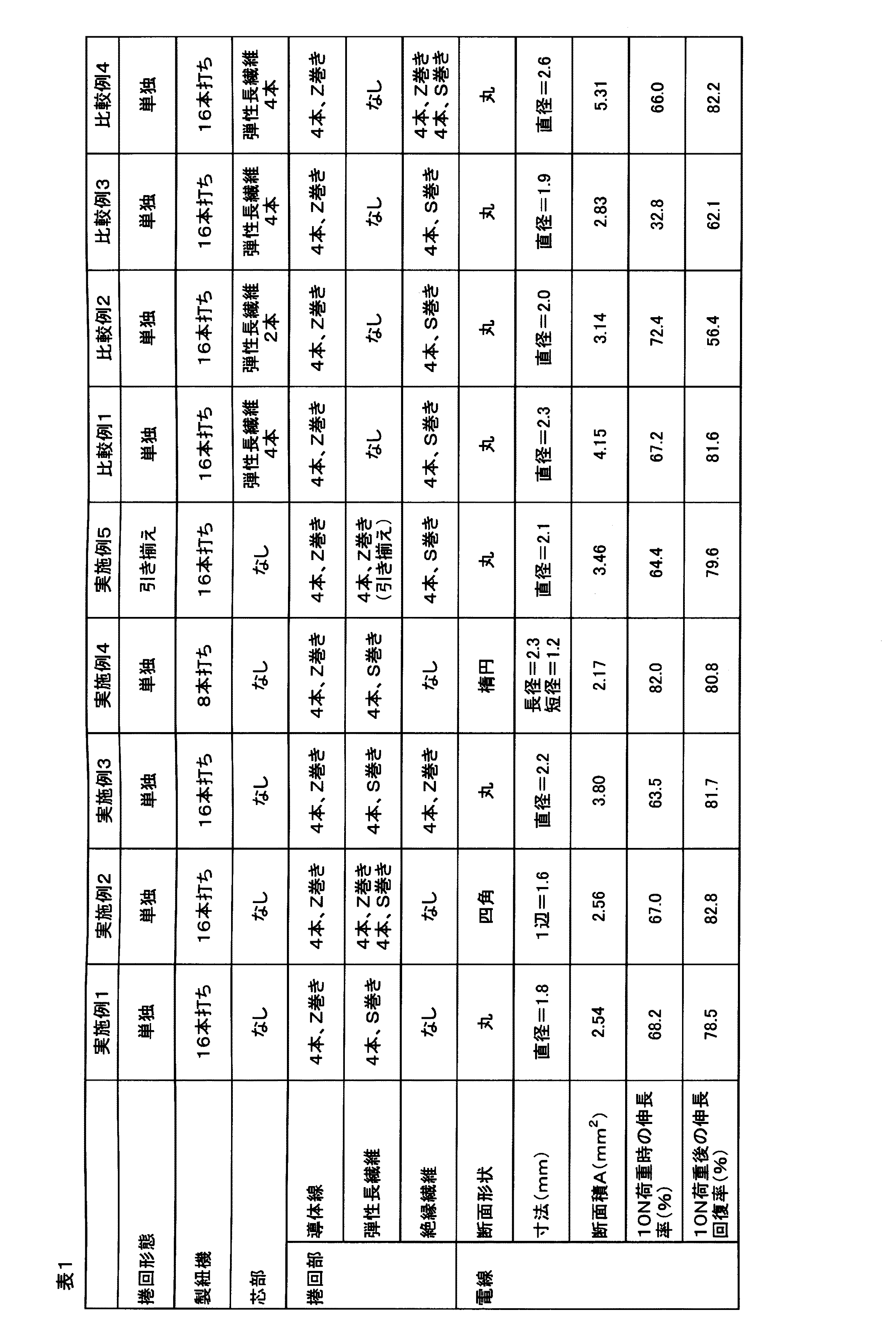
得られた伸縮電線の太さ、10N荷重時の伸び及び10N荷重後の伸長回復率の評価結果を表1に示す。
[Example 1]
940d using a double covering machine (made by Kataoka Techno Co., Ltd., SP-400 type)
While a tex / 72f polyurethane elastic long fiber (Asahi Kasei Fibers Co., Ltd., trade name: Leuka) is used as a core, a 155 dtex / 48f nylon false twisted yarn is twisted under 500 T / m while being stretched at a stretch ratio of 6 times ( S twist) and 332 T / m top twist (Z twist) to obtain a double cover yarn.
The obtained double cover yarn was placed on a bobbin winder for a string making machine with a yarn feeding roller (auto winder manufactured by Yoshida Seisakusho Co., Ltd.) and wound around the bobbin at an expansion ratio of 1.2. Moreover, as a conductor wire, a copper fine wire assembly wire (USTC manufactured by Tatsuno Electric Wire Co., Ltd., diameter 0.03 mm × 48 pieces) covered with polyester processed yarn was wound around a bobbin alone.
Using a 16-punch round stringing machine (manufactured by Sakurai Tekko Co., Ltd.), four bobbins each wound with a double cover yarn are arranged in the S twist direction every other bobbin 4 and each conductor wire is wound around the bobbin 4 The book was arranged every other Z-strand direction and subjected to braiding to obtain an expandable electric wire. As for the yarn weight at the time of the braiding process, 40 cm (about 150 g) was applied to the double cover yarn, and 20 cm (about 75 g) was applied to the conductor wire.
Table 1 shows the evaluation results of the thickness of the obtained elastic wire and the elongation at 10N load and the elongation recovery rate after 10N load.
[比較例1]
芯材として、実施例1と同様のダブルカバー糸を4本引き揃えて別途糸管に巻き取った。
16本打ちの丸打ち製紐機((有)桜井鉄工製)を用い、糸管に巻き取ったダブルカバー糸を2.0倍に伸長しながら芯部に供給し、実施例1と同様の導体線を巻き取ったボビン4本をZ撚り方向に1本おきに配置し、絶縁繊維であるナイロン仮撚糸(230dtex/72f×2本引き揃え)を巻き取ったボビン4本をS撚り方向に1本おきに配置して編組加工を行い、伸縮電線を得た。編組加工時の糸オモリは、導体線には20匁(約75g)、ナイロン仮撚糸には15匁(約56g)の糸オモリを掛けた。
得られた伸縮電線の太さ、10N荷重時の伸び及び10N荷重後の伸長回復率の評価結果を表1に示す。
[Comparative Example 1]
As a core material, four double cover yarns similar to those in Example 1 were drawn and wound around a yarn tube separately.
Using a 16-punch round punching string machine (manufactured by Sakurai Tekko Co., Ltd.), the double cover thread wound around the thread tube is supplied to the core while being stretched 2.0 times. Four bobbins around which conductor wires have been wound are arranged in the Z twist direction, and four bobbins wound with nylon false twisted yarn (230 dtex / 72f × 2), which is an insulating fiber, are wound in the S twist direction. Placing every other piece and performing braiding processing gave a telescopic wire. As for the yarn weight at the time of the braiding process, the conductor wire was hung with 20 mm (about 75 g) and the nylon false twisted yarn with 15 mm (about 56 g).
Table 1 shows the evaluation results of the thickness of the obtained elastic wire and the elongation at 10N load and the elongation recovery rate after 10N load.
[比較例2]
芯材として、実施例1と同様のダブルカバー糸を2本引き揃えて用いた以外は、比較例1と同様にして伸縮電線を得た。得られた伸縮電線の太さ、10N荷重時の伸び及び10N荷重後の伸長回復率の評価結果を表1に示す。
[Comparative Example 2]
A stretchable electric wire was obtained in the same manner as in Comparative Example 1 except that two double cover yarns similar to those in Example 1 were used as the core material. Table 1 shows the evaluation results of the thickness of the obtained elastic wire and the elongation at 10N load and the elongation recovery rate after 10N load.
[比較例3]
比較例1において、編組加工時の糸オモリを、導体線、ナイロン仮撚糸共に40匁(約150g)の糸オモリを掛けて、きつく捲回した以外は、比較例1と同様にして伸縮電線を得た。得られた伸縮電線の太さ、10N荷重時の伸び及び10N荷重後の伸長回復率の評価結果を表1に示す。
実施例1と比較例1は、弾性長繊維と導体線として同じものを用い、同じ製紐機を用いて伸縮電線を製造したものであるが、比較例1は弾性長繊維が芯部にあって導体線を拘束していないため、電線の形態を保持するために導体線とは反対方向に絶縁繊維を捲回したものである。
実施例1で得られた伸縮電線は、比較例1で得られた伸縮電線と比較すると、伸長率及び伸長回復率が同等で、電線の直径で約20%、断面積で約40%小さい、非常に細くコンパクトな伸縮電線であった。また、少なくとも芯材を引き揃えるコストと、絶縁繊維のコスト分は削減することができた。
比較例1で得られた伸縮電線は、伸長率並びに伸長回復率は実施例1の電線と同等のものであったが、太すぎるために本発明の目的には合致しないものであった。
比較例2は、比較例1の芯部の弾性長繊維を細くしたものであり、電線の直径はやや細くなったものの、いまだ実施例1の電線よりは太く、伸長回復率が大きく低下し、伸縮電
線としては不十分なものであった。
比較例3は、導体線及び絶縁繊維を比較例1よりもきつく巻き付けたものであり、電線の太さは実施例1の電線に近い太さまで細くできたものの、伸長率並びに伸長回復率の両方が大きく低下し、伸縮電線としては不十分なものであった。
[Comparative Example 3]
In Comparative Example 1, the stretchable electric wire was formed in the same manner as in Comparative Example 1 except that the yarn weight at the time of braiding was twisted tightly by winding 40 mm (about 150 g) of both conductor wire and nylon false twisted yarn. Obtained. Table 1 shows the evaluation results of the thickness of the obtained elastic wire and the elongation at 10N load and the elongation recovery rate after 10N load.
In Example 1 and Comparative Example 1, the same elastic long fibers and conductor wires were used, and the stretchable wires were manufactured using the same stringing machine. In Comparative Example 1, the elastic long fibers were in the core. Since the conductor wire is not restrained, the insulating fiber is wound in the opposite direction to the conductor wire in order to maintain the shape of the electric wire.
The stretchable wire obtained in Example 1 has an elongation rate and elongation recovery rate equivalent to those of the stretchable wire obtained in Comparative Example 1, with a wire diameter of about 20% and a cross-sectional area of about 40% smaller. It was a very thin and compact telescopic wire. In addition, at least the cost of arranging the core material and the cost of the insulating fiber could be reduced.
The stretchable wire obtained in Comparative Example 1 had the same elongation rate and stretch recovery rate as the wire of Example 1, but was too thick to meet the purpose of the present invention.
Comparative Example 2 is obtained by thinning the elastic long fiber of the core part of Comparative Example 1, and although the diameter of the electric wire is slightly reduced, it is still thicker than the electric wire of Example 1, and the elongation recovery rate is greatly reduced. It was insufficient as a telescopic wire.
In Comparative Example 3, the conductor wire and the insulating fiber were wound more tightly than in Comparative Example 1, and although the thickness of the electric wire was reduced to a thickness close to that of the electric wire of Example 1, both the elongation rate and the elongation recovery rate were Was greatly reduced, and it was insufficient as an expandable electric wire.
[実施例2]
ダブルカバー糸を巻き取ったボビン4本をZ撚り方向にも1本おきに配置した以外は、実施例1と同様にして伸縮電線を得た。得られた伸縮電線の太さ、10N荷重時の伸び及び10N荷重後の伸長回復率の評価結果を表1に示す。
得られた伸縮電線は、断面形状が略四角断面であり、弾性長繊維を実施例1対比で2倍使用しているにも係わらず、断面積は実施例1の伸縮電線と同程度であり、非常に細くコンパクトな伸縮電線であった。
[Example 2]
An expandable electric wire was obtained in the same manner as in Example 1 except that four bobbins around which the double cover yarn was wound were arranged every other bobbin in the Z twist direction. Table 1 shows the evaluation results of the thickness of the obtained elastic wire and the elongation at 10N load and the elongation recovery rate after 10N load.
The obtained expandable electric wire has a substantially square cross section, and the cross-sectional area is almost the same as that of the expandable electric wire of Example 1 although the elastic long fiber is used twice as compared with Example 1. It was a very thin and compact telescopic wire.
[実施例3]
導体線間の間隔をより均一にする目的で、比較例1と同様のナイロン仮撚糸を巻き取ったボビン4本をZ撚り方向に1本おきに配置した以外は、実施例1と同様にして伸縮電線を得た。得られた伸縮電線の太さ、10N荷重時の伸び及び10N荷重後の伸長回復率の評価結果を表1に示す。
[Example 3]
For the purpose of making the distance between the conductor wires more uniform, the same procedure as in Example 1 was conducted except that four bobbins each wound with the same nylon false twisted yarn as in Comparative Example 1 were arranged in the Z twist direction. An elastic wire was obtained. Table 1 shows the evaluation results of the thickness of the obtained elastic wire and the elongation at 10N load and the elongation recovery rate after 10N load.
[比較例4]
導体線間の間隔をより均一にする目的で、比較例1と同様のナイロン仮撚糸を巻き取ったボビン4本をZ撚り方向に1本おきに配置した以外は、比較例1と同様にして伸縮電線を得た。得られた伸縮電線の太さ、10N荷重時の伸び及び10N荷重後の伸長回復率の評価結果を表1に示す。
実施例3と比較例4は、弾性長繊維と導体線として同じものを用い、同じ製紐機を用いて伸縮電線を製造したものであるが、比較例4は電線の形態を保持するために導体線と反対方向に絶縁繊維を捲回したものである。実施例3で得られた伸縮電線は、比較例4で得られた伸縮電線と比較すると、伸長性が同等で、電線の直径で約15%、断面積で約30%小さい、非常に細くコンパクトな伸縮電線であった。また、少なくとも芯材を引き揃えるコストと、絶縁繊維のコスト分は削減することができた。
[Comparative Example 4]
In order to make the spacing between the conductor wires more uniform, the same procedure as in Comparative Example 1 was conducted except that four bobbins each wound with the same nylon false twisted yarn as in Comparative Example 1 were arranged in the Z twist direction. An elastic wire was obtained. Table 1 shows the evaluation results of the thickness of the obtained elastic wire and the elongation at 10N load and the elongation recovery rate after 10N load.
In Example 3 and Comparative Example 4, the same elastic fiber and conductor wire were used, and the telescopic wire was manufactured using the same stringing machine. Comparative Example 4 was for maintaining the shape of the wire. Insulating fiber is wound in the opposite direction to the conductor wire. The expandable electric wire obtained in Example 3 is very thin and compact compared with the expandable electric wire obtained in Comparative Example 4 with the same extensibility, approximately 15% smaller in diameter and 30% smaller in cross-sectional area. It was a flexible telescopic wire. In addition, at least the cost of arranging the core material and the cost of the insulating fiber could be reduced.
[実施例4]
8本打ちの丸打ち製紐機((有)桜井鉄工製)を用い、ダブルカバー糸を巻き取ったボビン4本をS撚り方向に配置し、導体線を巻き取ったボビン4本をZ撚り方向に配置して編組加工を行い、伸縮電線を得た。編組加工時の糸オモリは、ダブルカバー糸には40匁(約150g)、導体線には20匁(約75g)の糸オモリを掛けた。得られた伸縮電線の太さ、10N荷重時の伸び及び10N荷重後の伸長回復率の評価結果を表1に示す。
得られた伸縮電線は、断面形状が略楕円断面であり、断面積が実施例1の伸縮電線よりもさらに小さく、定荷重時の伸びが実施例1よりも大きい、非常に細くコンパクトで伸縮性に優れた伸縮電線であった。
[Example 4]
Using an 8-round stringing machine (manufactured by Sakurai Tekko Co., Ltd.), 4 bobbins wound with double cover yarn are placed in the S twist direction, and 4 bobbins wound with conductor wires are Z twisted. The wire was placed in the direction and braided to obtain an expandable electric wire. As for the yarn weight at the time of the braiding process, 40 cm (about 150 g) was applied to the double cover yarn, and 20 cm (about 75 g) was applied to the conductor wire. Table 1 shows the evaluation results of the thickness of the obtained elastic wire and the elongation at 10N load and the elongation recovery rate after 10N load.
The obtained expandable electric wire has a substantially elliptical cross section, a smaller cross-sectional area than the expandable electric wire of Example 1, and an elongation at constant load greater than that of Example 1. It was an excellent extension wire.
[実施例5]
実施例1と同様の導体線を製紐機用ボビンに巻き取る際に、実施例1と同様のカバリング糸を伸長倍率2.0倍で同じボビンに引き揃えて巻き取った。
16本打ちの丸打ち製紐機((有)桜井鉄工製)を用い、導体線とカバリング糸を引き揃えて巻き取ったボビン4本をZ撚り方向に1本おきに配置し、比較例1と同様のナイロン仮撚糸を巻き取ったボビン4本をS撚り方向に1本おきに配置して編組加工を行い、伸縮電線を得た。編組加工時の糸オモリは、導体線とカバリング糸を引き揃えたものには20匁(約75g)、ナイロン仮撚糸には15匁(約56g)の糸オモリを掛けた。得られた伸縮電線の太さ、10N荷重時の伸び及び10N荷重後の伸長回復率の評価結果を表1
に示す。
[Example 5]
When the same conductor wire as in Example 1 was wound around the bobbin for a stringing machine, the covering yarn similar to that in Example 1 was drawn and aligned on the same bobbin at an expansion ratio of 2.0.
Comparative Example 1 using a 16-punch round stringing machine (manufactured by Sakurai Tekko Co., Ltd.) and arranging four bobbins each having a conductor wire and covering yarn aligned and wound in the Z twist direction. Four bobbins each wound with the same nylon false twisted yarn were arranged every other in the S twist direction and subjected to braiding to obtain an expandable electric wire. The yarn weight at the time of braiding was 20 kg (about 75 g) when the conductor wire and covering yarn were aligned, and 15 kg (about 56 g) of the nylon false twisted yarn. Table 1 shows the evaluation results of the thickness of the obtained elastic wire and the elongation at 10N load and the elongation recovery rate after 10N load.
Shown in
本発明の伸縮電線は、ロボット分野をはじめとして、身体装着機器、衣服装着機器等、曲げ伸ばしなどの屈曲部を有する装置の配線に好適であり、特に、ヒューマノイド型ロボット(内部配線及び外皮配線)、パワーアシスト装置、ウエアラブル電子機器等に好適である。その他、各種ロボット(産業用ロボット、家庭用ロボット、ホビーロボット等)、リハビリ用補助具、バイタルデータ測定機器、モーションキャプチャー、電子機器付防護服、ゲーム用コントローラー(人体装着型を含む)、マイクロフォン、ヘッドフォン等の分野で好適に利用できる。 The expandable electric wire of the present invention is suitable for wiring of devices having bending portions such as bending devices such as body wearing devices and clothes wearing devices in the robot field, and particularly, humanoid robots (internal wiring and skin wiring). It is suitable for power assist devices, wearable electronic devices and the like. Other robots (industrial robots, home robots, hobby robots, etc.), rehabilitation aids, vital data measurement equipment, motion capture, protective clothing with electronic equipment, game controllers (including human-mounted type), microphones, It can be suitably used in the field of headphones and the like.
Claims (4)
Priority Applications (1)
| Application Number | Priority Date | Filing Date | Title |
|---|---|---|---|
| JP2008178695A JP5339798B2 (en) | 2008-07-09 | 2008-07-09 | Telescopic wire |
Applications Claiming Priority (1)
| Application Number | Priority Date | Filing Date | Title |
|---|---|---|---|
| JP2008178695A JP5339798B2 (en) | 2008-07-09 | 2008-07-09 | Telescopic wire |
Publications (2)
| Publication Number | Publication Date |
|---|---|
| JP2010020949A true JP2010020949A (en) | 2010-01-28 |
| JP5339798B2 JP5339798B2 (en) | 2013-11-13 |
Family
ID=41705644
Family Applications (1)
| Application Number | Title | Priority Date | Filing Date |
|---|---|---|---|
| JP2008178695A Expired - Fee Related JP5339798B2 (en) | 2008-07-09 | 2008-07-09 | Telescopic wire |
Country Status (1)
| Country | Link |
|---|---|
| JP (1) | JP5339798B2 (en) |
Citations (6)
| Publication number | Priority date | Publication date | Assignee | Title |
|---|---|---|---|---|
| JPS5392480A (en) * | 1977-01-25 | 1978-08-14 | Nippon Telegr & Teleph Corp <Ntt> | Transmission media |
| JPS6029316U (en) * | 1983-08-02 | 1985-02-27 | 三和電工株式会社 | wiring code |
| JPS6223021U (en) * | 1985-07-26 | 1987-02-12 | ||
| JPS6226814U (en) * | 1985-07-31 | 1987-02-18 | ||
| JPH0227610A (en) * | 1988-07-18 | 1990-01-30 | Toyobo Co Ltd | Elastic conductive wire and its manufacture |
| JPH05151830A (en) * | 1991-11-27 | 1993-06-18 | Yazaki Corp | Electric wire |
-
2008
- 2008-07-09 JP JP2008178695A patent/JP5339798B2/en not_active Expired - Fee Related
Patent Citations (6)
| Publication number | Priority date | Publication date | Assignee | Title |
|---|---|---|---|---|
| JPS5392480A (en) * | 1977-01-25 | 1978-08-14 | Nippon Telegr & Teleph Corp <Ntt> | Transmission media |
| JPS6029316U (en) * | 1983-08-02 | 1985-02-27 | 三和電工株式会社 | wiring code |
| JPS6223021U (en) * | 1985-07-26 | 1987-02-12 | ||
| JPS6226814U (en) * | 1985-07-31 | 1987-02-18 | ||
| JPH0227610A (en) * | 1988-07-18 | 1990-01-30 | Toyobo Co Ltd | Elastic conductive wire and its manufacture |
| JPH05151830A (en) * | 1991-11-27 | 1993-06-18 | Yazaki Corp | Electric wire |
Also Published As
| Publication number | Publication date |
|---|---|
| JP5339798B2 (en) | 2013-11-13 |
Similar Documents
| Publication | Publication Date | Title |
|---|---|---|
| TWI400722B (en) | Expandable electric cord and production method thereof | |
| JP5576961B2 (en) | Elastic optical signal transmission cable | |
| WO2009157070A1 (en) | Elastic signal transmission cable | |
| JP5354966B2 (en) | Telescopic wire | |
| JP2011082050A (en) | Expansive wire | |
| JP5872787B2 (en) | Multi-core telescopic cable for signal transmission | |
| JP5828743B2 (en) | Flexible cable | |
| JP2015026476A (en) | Multi-layer type stretchable transmission line | |
| JP2010040337A (en) | Highly durable expansion wire | |
| JP6345521B2 (en) | Terminal-processed elastic transmitter | |
| JP5339798B2 (en) | Telescopic wire | |
| JP2014096262A (en) | Shield-fitted telescopic electric wire | |
| JP6600494B2 (en) | Telescopic cable with excellent twisting resistance | |
| JP2010040339A (en) | Expansion wire | |
| JP2004134313A (en) | Expansive electric wire | |
| JP2009054312A (en) | Elastic optic fiber composite cable, and manufacturing method thereof | |
| JP6497927B2 (en) | Telescopic transmission line | |
| JP2021111588A (en) | Expansion electric wire and cable | |
| JP2019067709A (en) | Expansive electric wire | |
| JP2017183238A (en) | Stretchable electrical line | |
| JP2012216469A (en) | Electrical cable |
Legal Events
| Date | Code | Title | Description |
|---|---|---|---|
| A621 | Written request for application examination |
Free format text: JAPANESE INTERMEDIATE CODE: A621 Effective date: 20110629 |
|
| A131 | Notification of reasons for refusal |
Free format text: JAPANESE INTERMEDIATE CODE: A131 Effective date: 20130611 |
|
| A521 | Request for written amendment filed |
Free format text: JAPANESE INTERMEDIATE CODE: A523 Effective date: 20130716 |
|
| TRDD | Decision of grant or rejection written | ||
| A01 | Written decision to grant a patent or to grant a registration (utility model) |
Free format text: JAPANESE INTERMEDIATE CODE: A01 Effective date: 20130806 |
|
| A61 | First payment of annual fees (during grant procedure) |
Free format text: JAPANESE INTERMEDIATE CODE: A61 Effective date: 20130806 |
|
| R150 | Certificate of patent or registration of utility model |
Ref document number: 5339798 Country of ref document: JP Free format text: JAPANESE INTERMEDIATE CODE: R150 Free format text: JAPANESE INTERMEDIATE CODE: R150 |
|
| S111 | Request for change of ownership or part of ownership |
Free format text: JAPANESE INTERMEDIATE CODE: R313111 |
|
| R350 | Written notification of registration of transfer |
Free format text: JAPANESE INTERMEDIATE CODE: R350 |
|
| S531 | Written request for registration of change of domicile |
Free format text: JAPANESE INTERMEDIATE CODE: R313531 |
|
| R350 | Written notification of registration of transfer |
Free format text: JAPANESE INTERMEDIATE CODE: R350 |
|
| LAPS | Cancellation because of no payment of annual fees |