JP2010020929A - Structure for fixation of cigar plug - Google Patents
Structure for fixation of cigar plug Download PDFInfo
- Publication number
- JP2010020929A JP2010020929A JP2008178066A JP2008178066A JP2010020929A JP 2010020929 A JP2010020929 A JP 2010020929A JP 2008178066 A JP2008178066 A JP 2008178066A JP 2008178066 A JP2008178066 A JP 2008178066A JP 2010020929 A JP2010020929 A JP 2010020929A
- Authority
- JP
- Japan
- Prior art keywords
- plug
- cigar
- pressing
- spring material
- fixing member
- Prior art date
- Legal status (The legal status is an assumption and is not a legal conclusion. Google has not performed a legal analysis and makes no representation as to the accuracy of the status listed.)
- Granted
Links
- 235000019506 cigar Nutrition 0.000 title claims abstract description 168
- 239000000463 material Substances 0.000 claims abstract description 59
- 238000003780 insertion Methods 0.000 claims abstract description 22
- 230000037431 insertion Effects 0.000 claims abstract description 22
- 238000010276 construction Methods 0.000 claims 1
- 210000000078 claw Anatomy 0.000 description 6
- 239000002184 metal Substances 0.000 description 5
- 229910052751 metal Inorganic materials 0.000 description 5
- 238000005452 bending Methods 0.000 description 4
- 230000007423 decrease Effects 0.000 description 2
- 239000013013 elastic material Substances 0.000 description 2
- RYGMFSIKBFXOCR-UHFFFAOYSA-N Copper Chemical compound [Cu] RYGMFSIKBFXOCR-UHFFFAOYSA-N 0.000 description 1
- 239000002390 adhesive tape Substances 0.000 description 1
- 235000019504 cigarettes Nutrition 0.000 description 1
- 229910052802 copper Inorganic materials 0.000 description 1
- 239000010949 copper Substances 0.000 description 1
- 230000000694 effects Effects 0.000 description 1
- 239000011810 insulating material Substances 0.000 description 1
- 230000001788 irregular Effects 0.000 description 1
- 239000007769 metal material Substances 0.000 description 1
- 238000000034 method Methods 0.000 description 1
- 239000011347 resin Substances 0.000 description 1
- 229920005989 resin Polymers 0.000 description 1
Images


Abstract
Description
本発明は、自動車用シガープラグの固定構造の改良に関する。 The present invention relates to an improvement in a structure for fixing a cigar plug for an automobile.
近年では、車室内をより便利で快適に過ごすために様々な後付けの電気機器(例えば、車内脱臭装置、コンパクトディスクプレーヤー、テレビ、無線機、家庭用ゲーム機、カーナビゲーションシステム、パーソナルコンピュータ或いは小型の冷蔵・保温ボックスなど)が使用されるようになっている。 In recent years, various retrofit electric devices (for example, in-car deodorizers, compact disc players, TVs, radios, home game consoles, car navigation systems, personal computers or small computers) Refrigerated / insulated boxes, etc.) are being used.
これら電気機器の電源には主として自動車のバッテリーが使用され、バッテリーと電気的に接続されているシガーソケットに、電気機器の電源コードの先端に備えられたシガープラグとほぼ同一径の後付けプラグを差し込むことで電力の供給を受けている。 The power source of these electric devices is mainly an automobile battery, and a retrofitted plug of the same diameter as the cigar plug provided at the tip of the power cord of the electric device is inserted into a cigar socket electrically connected to the battery. It is supplied with power.
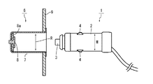
ここで、一般的なシガープラグならびにシガーソケットの構造について簡単に説明しておくと、シガープラグ1は、図11に示すように、棒状のプラグ本体2と、プラグ本体2の先端に突設された第1接触子3と、プラグ本体2の側壁から両側に突設された第2接触子4,4とを有する。第2接触子4,4は、内部に設けられたバネによって常時外方に押圧付勢されている。
Here, the structure of a general cigar plug and cigar socket will be briefly described. As shown in FIG. 11, the cigar plug 1 protrudes from a rod-
一方、シガーソケット6は、円筒状の金属製プラグ受容筒体7と、絶縁材8aを介してプラグ受容筒体7の筒底に設けられた端子板8と、これらを収容するケーシング9とを有する。
On the other hand, the
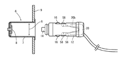
シガーソケット6のプラグ受容筒体7にシガープラグ1を挿入すると、第1接触子3の先端が端子板8と当接し、両第2接触子4,4の外面がプラグ受容筒体7の内壁と当接する。第2接触子4,4は、上述したように内部に設けられたバネによって常時外方に押圧付勢されており、プラグ受容筒体7に対するプラグ本体2の寸法が適切であることと相俟ってこの押圧付勢力によってシガープラグ1がシガーソケット6にしっかりと保持される。
When the cigar plug 1 is inserted into the
ところで、シガープラグやシガーソケットの大きさについては統一された規格がなく、製造メーカーによってサイズが微妙に異なっているのが実情である。そのため、同一車種の備え付け純正品同士では、プラグ受容筒体7に対するプラグ本体2の寸法が適切であることから第2接触子4,4による上記押圧付勢力が適正に働いてプラグ保持力に問題がないとしても、シガープラグ1またはシガーソケット6のどちらか一方(或いは両方)が純正品でない場合には、プラグ受容筒体7に対するプラグ本体2の寸法が不適切となり、第2接触子4,4による押圧付勢力が適正に働かずプラグ保持力に支障が生じる場合がある。
By the way, there is no standard for the size of cigar plugs and cigar sockets, and the actual situation is that the sizes differ slightly depending on the manufacturer. For this reason, since the dimensions of the plug
すなわち、備え付けのシガーソケットを使用して形状的に該シガーソケットに装着できるようなシガープラグが設けられている後付け電気機器(後付けシガーソケットも含む。)を使用することがあるが、この場合、(1)備え付け純正シガーソケットに前述のような後付け電気機器のシガープラグ状の後付けプラグを挿入する場合、(2)後付け電気機器の後付けソケットに純正プラグを挿入する場合、(3)後付け電気機器の後付けソケットに他社後付けプラグを挿入する場合(以下、純正,後付けを含めて単にシガーソケット、シガープラグと言う。)があるが、この場合、プラグ本体2に対するプラグ受容筒体7の寸法が微妙に大きいとグラグラして第2接子4,4による上記押圧付勢力を十分に確保することができずに接触不良が起こり、甚だしい場合には、運転中の振動によってシガープラグ1がシガーソケット6から不所望に脱け落ちてしまうというような問題があった。
That is, there may be used a retrofit electric device (including a retrofit cigar socket) provided with a cigar plug that can be mounted on the cigar socket in shape using the provided cigar socket. (1) When inserting a cigar plug-like retrofit plug of a retrofit electrical device as described above into a genuine genuine cigar socket, (2) When inserting a genuine plug into a retrofit socket of a retrofit electrical device, (3) Retrofit electrical device There are cases where other company's retrofit plugs are inserted into the retrofit sockets (hereinafter referred to simply as cigar sockets and cigar plugs, including genuine and retrofit). In this case, the dimensions of the
そこで、従来は、例えば特許文献1に示すように、筒状のプラグ固定部材をシガープラグに取り付け、プラグの先端側がプラグの摘み部側に向かうにつれて外径が漸増するようにして該プラグ固定部材が装着されたシガープラグをシガーソケットに挿入することによってシガーソケットに対するシガープラグの保持力を高め、上述した問題に対処していた。
従来技術において、シガーソケットに対するシガープラグの保持力を高めるためには、プラグ固定部材が装着されたシガープラグをシガーソケットにしっかりと押し込む必要があるが、この押し込み力が強過ぎると、シガープラグをシガーソケットから引き抜こうとした場合に簡単に引き抜くことができなくなるという問題があった。 In the prior art, in order to increase the holding power of the cigar plug against the cigar socket, it is necessary to push the cigar plug with the plug fixing member firmly into the cigar socket, but if this pushing force is too strong, When trying to pull out from the cigar socket, there was a problem that it could not be pulled out easily.
本発明は、かかる従来の問題点に鑑みてなされたものであり、シガーソケットへのシガープラグの挿脱作業が簡単で、しかも、使用時においてシガーソケットからシガープラグが脱落することのないシガープラグの固定構造を提供することにある。 The present invention has been made in view of such conventional problems, and the cigar plug can be easily inserted into and removed from the cigar socket, and the cigar plug does not fall out of the cigar socket during use. It is to provide a fixed structure.
請求項1に記載した発明は、「自動車のシガーソケットに挿入されたシガープラグを固定するシガープラグの固定構造であって、シガープラグ10のプラグ本体12の側壁に等角度間隔で形成された複数の開口34のそれぞれにその径方向に移動可能に設けられている押圧固定部材58と、押圧固定部材58の広がり幅Xがシガーソケットに設けられているプラグ受容筒体の内径Rよりも大きくなるように押圧固定部材58を拡径方向に弾発付勢するバネ材56と、プラグ本体12の後端部にその軸方向に移動可能に設けられ、プラグ本体12の先端側へ移動させたときに押圧固定部材58の広がり幅Xがプラグ受容筒体の内径Rよりも小さくなるようにバネ材56を撓ませ、外力を除荷したときにバネ材56の弾発力によって反対側へ移動してバネ材56を拡径させる切替部材20とを備える」ことを特徴とするシガープラグの固定構造である。
The invention described in claim 1 is “a cigar plug fixing structure for fixing a cigar plug inserted into a cigar socket of an automobile, and a plurality of
この発明において、シガープラグ10をシガーソケットに挿入する際には、切替部材20を操作してバネ材56を撓ませる。バネ材56を撓ませると、押圧固定部材58の広がり幅Xが狭まり、プラグ受容筒体の内径Rよりも小さくなる。したがって、シガープラグ10をシガーソケットに挿入する際、押圧固定部材58がその挿入作業の妨げとなることはない。
In this invention, when the
一方、シガーソケットにシガープラグ10を挿入した後は、切替部材20に加えていた外力を除荷すればよく、たとえば、切替部材20を指で押していた場合には、切替部材20から指を離せばよい。すると、バネ材56がその弾発力によって拡径するとともに押圧固定部材58を拡径方向に移動させる。
On the other hand, after inserting the
ここで、バネ材56は押圧固定部材58の広がり幅Xがプラグ受容筒体の内径Rよりも大きくなるように押圧固定部材58を拡径方向に弾発付勢する。換言すれば、たとえシガープラグに対する寸法が不適切であっても、シガーソケットはこの押圧固定部材58によって内側から外方へ向けてしっかりと押圧されることとなり、これにより、シガーソケットに対するシガープラグ10の保持力が高められる。
Here, the
請求項2に記載した発明は、「バネ材56は、プラグ後端側からプラグ先端側に向かうにしたがってプラグの中心からその間隔が広がるように外方に延びた複数の羽根56bを有し、切替部材20のプラグ先端側端部には、凹所20dが形成されており、羽根56bの外面が凹所20dの開口縁部と接触するように羽根56bのプラグ後端側端部が凹所20dに挿入されている」ことを特徴とする。
The invention described in
本発明は、請求項1の切替部材20の構造を具体的にしたもので、切替部材20を指で押圧してプラグ本体12の先端側に移動させると、バネ材56を構成している羽根56bの外面が凹所20dの開口縁部に押されて凹所20d内に挿入されつつ撓み、これにより押圧固定部材58の広がり幅Xが狭められる。反対に切替部材20から指を離すと、バネ材56がその弾発力によって切替部材20を押し出しつつ拡径して押圧固定部材58の広がり幅Xを広げるとともに前記押し出し作用にて切替部材20が羽根56bの外面に沿ってプラグ後方に移動して元の位置へと戻る。これにより、シガープラグ10をシガーソケットに装着する場合、或はシガープラグ10をシガーソケットに装着した状態から取り外す場合、切替部材20を指操作するだけで簡単に挿脱することが出来るようになる。
The present invention is specific to the structure of the switching
請求項3に記載した発明は、「自動車のシガーソケットに挿入されたシガープラグを固定するシガープラグの固定構造であって、シガーソケット60のプラグ受容筒体64の側面両側、プラグ挿入開口側或いはこれとは反対側にてプラグ受容筒体64に挿入されているシガープラグを挟むように互いに対向する位置に設けられている一対の押圧固定部材92と、可撓性を有し、一対の押圧固定部材92同士を互いに近接離間可能に支持するバネ材90と、プラグ受容筒体64の近傍にてその軸方向にスライド可能に設けられ、軸方向一方側へスライドさせたときには押圧固定部材92の広がり幅Yがプラグ本体12の外径Mよりも小さくなるようにバネ材90を撓ませ、反対側へスライドさせたときには押圧固定部材92の広がり幅Yがプラグ本体12の外径Mよりも大きくなるようにバネ材90を拡径させる切替部材70とを備えている」ことを特徴とするものである。
The invention described in
この発明では、切替部材70をプラグ受容筒体64の軸方向にスライドさせることによって、押圧固定部材92の広がり幅Yを変化させることができる。
In the present invention, the spread width Y of the pressing and fixing
すなわち、切替部材70を軸方向一方側へスライドさせると、バネ材90が撓んで押圧固定部材92の広がり幅Yが狭まり、シガーソケット60に挿入されているシガープラグの側壁をその両側から挟持することができるので、これにより、シガーソケット60に対するシガープラグの保持力が高められる。
That is, when the switching
一方、切替部材70を反対側へスライドさせると、バネ材90が拡径して押圧固定部材92の広がり幅Yがプラグ本体12の外径Mよりも大きくなるので、シガーソケット60へのシガープラグの挿脱作業を何等の支障なく簡単に行うことができる。
On the other hand, when the switching
請求項4に記載した発明は、「バネ材90は、断面略U字状に屈曲形成された細長で可撓性を有する板材であり、切替部材70は、一端側に狭幅部71aが形成され、反対側に広幅部71bが形成され、狭幅部71aから広幅部71bに向かう内側面71cが次第に広幅となるようにテーパ状に形成された長孔71を有する板状の部材であり、バネ材90の先端部90aが長孔71に嵌め込まれている」ことを特徴とするものである。
The invention described in
本発明は、請求項3の切替部材70を具体的にしたもので、バネ材90の先端部90aが長孔71の狭幅部71aに位置するように切替部材70をスライドさせることにより、バネ材90の間隔が狭められて押圧固定部材92が縮径状態となる。反対に、先端部90aが長孔71の広幅部71bに位置するように切替部材70をスライドさせることにより、バネ材90の間隔が広げられて押圧固定部材92が拡径状態となる。この場合も切替部材70のスライドだけでシガーソケット60へのシガープラグの挿脱作業を何等の支障なく簡単に行うことができる。
The present invention is a specific example of the switching
請求項1〜4に記載の発明によれば、後付けと正規部品との組み合わせ或いは後付け部品同士の組み合わせにおいて、シガープラグとシガーソケットとの間で寸法に若干の誤差があったとしてもシガープラグのシガーソケットへの挿脱作業が簡単で、しかも、使用時においてシガーソケットからシガープラグが脱落することのないシガープラグおよびシガーソケットを提供できた。 According to the invention described in claims 1 to 4, even if there is a slight error in dimensions between the cigar plug and the cigar socket in the combination of the retrofit and the regular parts or the combination of the retrofit parts, It was possible to provide a cigar plug and a cigar socket that can be easily inserted into and removed from the cigar socket and that the cigar plug does not fall out of the cigar socket during use.
[第1実施例]
以下、本発明の第1実施例を図面に従って説明する。第1実施例は、「シガープラグの固定構造」がシガープラグ側に設けられている例である。図1は、本発明の第1実施例のシガープラグ10を示す正面図であり、図2は、シガープラグ10の平面図であり、図3は、シガープラグ10の右側面図であり、図4は、図1におけるA−A断面図である。
[First embodiment]
Hereinafter, a first embodiment of the present invention will be described with reference to the drawings. The first embodiment is an example in which the “cigar plug fixing structure” is provided on the cigar plug side. FIG. 1 is a front view showing a
図1〜図4に示すように、シガープラグ10は、プラグ本体12、第1接触子14、第2接触子16、バネ材56、押圧固定部材58および切替部材20により大略構成されている。
As shown in FIGS. 1 to 4, the
プラグ本体12は、後述する第1接触子14、第2接触子16、バネ材56、押圧固定部材58および切替部材20を収容するものであり、ケーシング12aと前側固定部材12bと後側固定部材12cとで構成されている。
The
ケーシング12aは、円筒状の部材であり、その軸方向一方端部(挿入先端部)には、雄ネジ32が形成されている。ケーシング12aの側壁には、2つの開口34が互いに対向する位置に形成されている(つまり、プラグ本体12を構成しているケーシング12aの側壁に2つの開口34が180度間隔で形成されている)。また、ケーシング12aの後端部外面には、周方向に延びる突条36が形成されている。なお、本実施例において、ケーシング12aは下側ケーシング12a1と上側ケーシング12a2とに上下2分割されている。
The
ケーシング12aの内部には、挿入先端側(図4における左側)から後端側にかけて第1接触子収容部22、第2接触子取付部24、コード孔26、バネ材取付部28、スライド溝30がそれぞれ形成されている(図4参照)。
Inside the
前側固定部材12bは筒状の部材であり、その内側面の挿入先端側開口部には、係止爪46が突設されている。前側固定部材12bの内側面の後端部側には、雌ネジ44が刻設されており、この雌ネジ44をプラグ本体12の雄ネジ32に螺合することによって上下に2分割されたプラグ本体12がその前側において保持されている(図1および図4参照)。
The front
後側固定部材12cはリング状の部材であり、この後側固定部材12cをケーシング12aの後端部に嵌合することによって上下に2分割されたプラグ本体12がその後側において保持されている。なお、後側固定部材12cの厚みは、その外面がケーシング12aの突条36の外面と略面一となるように設定されている。
The rear
第1接触子14は、つるまきばね48とヒューズ50とキャップ端子52とで構成されており、つるまきばね48とヒューズ50の後端部とが第1接触子収容部22に収容されている(図4参照)。
The
つるまきばね48は、その一端側が大径で他端側に向かうにつれて次第に縮径するように形成されており、その大径側端部が第1接触子収容部22の内面に突設された係止片22aと当接している。なお、シガープラグ10の使用時には、図4の点線で示すように、つるまきばね48の大径側端部に導電線Sが接続される。
The
つるまきばね48の小径側の外径は、後述するヒューズ50の外径よりも小さめに設定されており、この小径側端部と接するようにヒューズ50が配置されている。
The outer diameter on the small diameter side of the
ヒューズ50は、シガープラグ10に過大な電流が流れたときにこれに接続されている電気機器を保護するものであり、周知構造のものがそのまま適用される。ヒューズ50の前端部には、キャップ端子52が取り付けられている。
The
キャップ端子52は、その後端部側が開口しており、挿入先端部側が閉塞されているキャップ状の部材であり、その閉塞端部が前側固定部材12bの先端から外方に突出している。キャップ端子52の開口端部には、係止鍔52aがその全周に亘って形成されており、この係止鍔52aが前側固定部材12bの係止爪46に弾発状にて係止されている。
The
なお、プラグ本体12内に第1接触子14を収容した状態では、つるまきばね48が自然長よりも縮んだ状態となっている。したがって、ヒューズ50およびキャップ端子52は、つるまきばね48の弾発力を受けて挿入先端側に常時押圧付勢されることになる。
In addition, in the state which accommodated the
第2接触子16は、銅などの導電性金属材料からなる細長の板材を曲折形成したものであり、その中央部分がU字に屈曲形成されている(本実施例では、このU字状に曲げられた屈曲部16aが第2接触子取付部24に取り付けられている)。
The
第2接触子16の屈曲部16aよりも先端側は、外方に膨出しており、この膨出部16bがケーシング12aの左右両側の開口34からそれぞれ外方に突出している。第2接触子16の先端部16cは、ケーシング12aの内壁に係止されている。
The distal end side of the
バネ材56は、細長の金属板材をその中央部分で二つ折りにして略く字状に屈曲形成したもので、その屈曲部分56aをバネ材取付部28に引っ掛けるようにしてバネ材56がケーシング12aに取り付けられている。
The
バネ材56の屈曲部分56aから繋がる2枚の羽根56bは、それぞれプラグの中心からその間隔が広がるよう外方に向かって延びている。各羽根56bの先端は、互いに平行となるように内側へ若干屈曲されており、その先端屈曲部分の外面には係止爪56cが切り起こし突設されており、この係止爪56cに押圧固定部材58が取り付けられている。
The two
押圧固定部材58は、ゴムなどの弾性材料からなるブロック状のもので、この押圧固定部材58の凹凸状に形成された外面がケーシング12aの開口34から外方に突出している。
The pressing and fixing
なお、一方の押圧固定部材58の外面から他方の押圧固定部材58の外面までの距離が押圧固定部材58の広がり幅Xであり(図2参照)、拡径状態における広がり幅Xがシガーソケットのプラグ受容筒体の内径Rよりも大きくなり、縮径状態における広がり幅Xがシガーソケットのプラグ受容筒体の内径Rよりも小さくなるようにバネ材56ならびに押圧固定部材58の形状が適宜設定されている。
The distance from the outer surface of one pressing and fixing
切替部材20は、押圧固定部材58を拡径状態から縮径状態(或いはその逆)となるようにするためのもので、円盤状のプッシュスイッチ20aと、プッシュスイッチ20aの挿入先端側端面から突設された二股のガイド部材20bとを有する(図4参照)。
The switching
プッシュスイッチ20aの外面には、鍔20cがその全周に亘って形成されており、この鍔20cがケーシング12aの後端内周全周にて前記鍔20cの幅より広い幅で凹設されたスライド溝30に嵌り込んでいる。これにより、切替部材20がスライド溝30内をその前後方向に移動できるようになっている。
On the outer surface of the
二股に分かれたガイド部材20bの間に形成された凹所20dには、上述したバネ材56の屈曲部分56aが嵌り込んでおり、各ガイド部材20bの先端(凹所20dの開口縁部)がバネ材56の羽根56bの外面とそれぞれ接触している。
The
以上のように構成されたシガープラグ10の使用方法について述べる。シガープラグ10を使用する際には、シガープラグ10の後端部を掴んで、その後端部に設けられている切替部材20(プッシュスイッチ20a)を指で押す。すると、プッシュスイッチ20aは、2本のガイド部材20bがバネ材56の外面に沿ってバネ材56を撓めつつ前進し、押圧固定部材58の広がり幅Xを次第に狭める。
A method of using the
そして、切替部材20(プッシュスイッチ20a)を一番奥まで押し込むと押圧固定部材58の広がり幅Xが最小となり、このときの広がり幅Xはシガーソケットのプラグ受容筒体の内径Rよりも小さくなる。したがって、シガープラグ10をシガーソケットに挿入する際に、押圧固定部材58がシガープラグ10の挿入作業の妨げになるようなことはなく、その挿入作業を簡単に行うことができる(図5〜図6参照)。
Then, when the switching member 20 (push
シガープラグ10のシガーソケットへの挿入作業が完了すれば、切替部材20(プッシュスイッチ20a)から指を離す。すると、バネ材56には元の形状に戻ろうとする弾発力が働いてバネ材56が拡径する。バネ材56が拡径すると、押圧固定部材58の広がり幅Xも広がり、ゴム製で表面に凹凸が設けられている押圧固定部材58がソケットのプラグ受容筒体の内側面を内側から外側に向けて押圧する。これにより、シガーソケットに対するシガープラグ10の保持力が大いに高められ、たとえ少なくともいずれか一方が後付け部品であって両者間に僅かな寸法誤差があったとしても、運転中の振動等によるシガープラグ10のシガーソケットからの脱落を確実に防止することができる。この時、第1接触子14の先端はシガーソケットの端子板8と当接し、両第2接触子4,4の外面がプラグ受容筒体7の内壁に当接して給電可能状態となっている。
When the insertion operation of the
このように、本実施例では、バネ材56と押圧固定部材58との協働作業によって両者間の微小な寸法誤差が埋められ、確実な「シガープラグの固定構造」が構成されることになる。
As described above, in this embodiment, a small dimensional error between the two is filled by the cooperative operation of the
一方、シガープラグ10をシガーソケットから取り外すときは、シガープラグ10をシガーソケットに挿入するときと同様、切替部材20のプッシュスイッチ20aを押してバネ材56の広がり幅Xを狭めて縮径状態にすればよく、これにより、シガープラグ10のシガーソケットからの抜き取り作業を簡単に行なうことができる。
On the other hand, when the
なお、上述実施例では、プラグ本体12の側壁に押圧固定部材58を2個設けた例を示したが、押圧固定部材58を3個以上設けるようにしてもよい。この場合、プラグ本体12の側壁に設ける開口34やバネ材56の羽根56bならびに切替部材20のガイド部材20bの数も押圧固定部材58の数に応じて適宜設定されることになる。全ての押圧固定部材58の外面を通る円の直径(最大外径)が、押圧固定部材58の広がり幅Xとなる。
In the above-described embodiment, the example in which the two pressing fixing
押圧固定部材58による均一な保持力を得るためには、押圧固定部材58をプラグ本体12の側壁に等角度間隔(押圧固定部材58を3個配置する場合は120度間隔)で配置するのが望ましい。
In order to obtain a uniform holding force by the pressing and fixing
[実施例2]
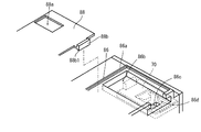
次に本発明の第2実施例を図7〜図10に基づいて説明する。第2実施例は、「シガープラグの固定構造」がシガーソケット側に設けられている例である。なお、図7は、本発明の第2実施例にかかるシガーソケット60を示す斜視図であり、図8は、図7におけるB−B断面図であり、図9は、後述するケーシング62の構成を示す部分拡大斜視図(一部省略)であり、図10は、後述するバネ材90と切替部材70との関係を示す部分拡大斜視図(一部省略)である。
[Example 2]
Next, a second embodiment of the present invention will be described with reference to FIGS. The second embodiment is an example in which a “cigar plug fixing structure” is provided on the cigar socket side. 7 is a perspective view showing a
これらの図から分かるように、シガーソケット60は、ケーシング62、プラグ受容筒体64、端子板66、バネ材90、押圧固定部材92および切替部材70により大略構成されている。
As can be seen from these drawings, the
ケーシング62は、後述するプラグ受容筒体64、端子板66、バネ材90、押圧固定部材92および切替部材70を収容する箱状のものであり、下側ケーシング62aと上側ケーシング62bとで構成されている。
The
下側ケーシング62aは、その上面と前面とが開口した箱状の部材であり、その内部には、端子板係止溝72、ソケット係止溝74、ソケット保持部76、バネ材取付部78および図示しないコード孔が形成されている(図8参照)。
The
上側ケーシング62bは、下側ケーシング62aの上面と前面とを覆う断面略逆M字状の部材で、その天井面には、端子板係止溝(図示省略)、ソケット係止溝94、ソケット保持部(図示省略)およびバネ材挿入孔86cが形成されている。
The
上側ケーシング62bの前面には、円形状に形成された2個のプラグ挿脱用通孔82が左右に並んで形成されており、上側ケーシング62bの上面には、切替部材取付部84が一体的に膨出状にて形成されている。
Two circular plug insertion / removal holes 82 are formed on the front surface of the
切替部材取付部84は、取付部本体86と閉塞板88とで構成されている。前記取付部本体86は、矩形ブロック状の部材であり、その上面外縁に沿って閉塞板88が嵌り込むように段状外畝部86aが凸設されており、更に段状外畝部86aの内側において該上面の左右両側には、前後方向に延び前端が切り欠かれている切替部材70の前後方向スライド用の2つのスライド溝86bが並んで凹設されている(図9参照)。各スライド溝86bの溝底には、上述したバネ材挿入孔86cが開口している。前記段状外畝部86aにおけるスライド溝86b近傍に設けた切り欠き部分が切欠部86dである。
The switching
閉塞板88は、前記段状外畝部86aに嵌り込んで取付部本体86の上面を覆う板状のもので、その後端部には、矩形状のツマミ用矩形孔88aがスライド溝86bと対応する位置に形成され、その前端部には、前記切欠部86dに嵌まり込むストッパー88bが形成されている。ストッパー88bの前端には下方に向けて係止突起88b1が突設されている。
The closing
プラグ受容筒体64は、導電性を有する金属からなる筒状の部材であり、そのプラグ挿入側が僅かに拡径しており、その開口端に外鍔64bが形成されている。プラグ受容筒体64の反対側の上下両端部には、上下に向けて2つの係止爪64aが折曲にて形成されており、この両係止爪64aが下側ケーシング62aのソケット係止溝74および上側ケーシング62bのソケット係止溝94にそれぞれ係止されている。
The
端子板66は、導電性を有する金属からなる板状の部材であり、その下端端縁が端子板係止溝72に係止されている。なお、シガーソケット60の使用時には、端子板66と上記プラグ受容筒体64にバッテリーから導出された電力供給コード(図示省略)が接続される。
The
バネ材90は、細長の金属帯材を略U字状に屈曲形成したものであり、その底面が下側ケーシング62aのバネ材取付部78にネジ止めされている。バネ材90の先端部分は内側に屈曲しており、その先端部90aが後述する切替部材70の長孔71内に嵌り込んでいる。そして前記先端部90aは、長孔71内を円滑にスライドするように外向き円弧状に形成されている。バネ材90の左右両側の羽根90bの内側面には、ゴムなどの弾性材料からなる押圧固定部材92が粘着テープにより貼り付けられている。なお、一方の押圧固定部材92の外面から他方の押圧固定部材92の外面までの距離が押圧固定部材92の広がり幅Yである(図8および図10参照)。
The
切替部材70は、樹脂製の板状部材であり、取付部本体86のスライド溝86bにその前後方向(プラグ受容筒体64の軸方向)にスライド可能に取り付けられている。切替部材70の中央には、その前後方向に延びる長孔71が形成されており、この長孔71に上述したバネ材90の先端部90aが嵌め込まれている。ここで、長孔71は、その前側(プラグ挿入側)が小幅に形成され、この部分が狭幅部71aであり、反対側に向かうにしたがって次第に広幅となるようにその内側面がテーパ状に形成されており、広幅部分に繋がっている。前記広幅部分が広幅部71b、テーパ部分がテーパ部71cである。そして広幅部71bにバネ材90の先端部90aが嵌り込んだ状態では、バネ材90の間隔が広がって押圧固定部材92の広がり幅Yが最大となり、狭幅部71aに嵌り込んだ状態では、バネ材90の間隔が狭まってプラグ本体の外径Mより狭い状態で押圧固定部材92の広がり幅Yが最小となる。
The switching
なお、押圧固定部材92の広がり幅Yが最大のとき、その広がり幅Yはプラグ受容筒体64の内径R(少なくとも、プラグ本体の外径M)よりも大きくなり、押圧固定部材92の広がり幅Yが最小のとき、その広がり幅Yは、プラグ受容筒体64に挿入されたシガープラグをその両側から狭持できるようにプラグ受容筒体64の内径R(より具体的には、プラグ本体の外径M)よりも小さくなるようにバネ材90の形状が適宜設定され、プラグ本体の外面に弾接できるようになっている。
When the spreading width Y of the pressing and fixing
切替部材70の上面であってその挿入側端部端縁には、閉塞板88のストッパー88bの係止突起88b1が嵌り込む嵌合凹部70aが形成されている。また、切替部材70の上面後端部には、ツマミ70bが突設されている。
On the upper surface of the switching
ソケット保持部76は、プラグ受容筒体64を上下から保持できるようにプラグ受容筒体64との接触面は円弧状に形成されている。
The
以上のように構成されているシガーソケット60を使用する際には、切替部材70のツマミ70bを摘んで切替部材取付部84から引き出す。この時、ストッパー88bの係止突起88b1が切替部材70の嵌合凹部70aに軽く係合しているが、ストッパー88b或は係止突起88b1の撓みによって係合部分を乗り越えて係合が解除されることになり、係合解除によりバネ材90の先端部90aを長孔71の広幅部71bに移動させることができる。このような移動によりバネ材90の間隔がその弾発力により広がって押圧固定部材92の広がり幅Yが最大となる。
When using the
上述したように、押圧固定部材92が拡径状態にあるとき、その広がり幅Yはプラグ本体の外径Mよりも大きくなるように設定されているので、シガープラグをシガーソケット60に挿入する際に押圧固定部材92に引っ掛らず、円滑に挿入できる。
As described above, when the pressing and fixing
シガーソケット60へのシガープラグの挿入作業が完了すると、今度は、切替部材70をスライド溝86bの奥まで押し込み、バネ材90の先端部90aを長孔71の狭幅部71aに移動させる。すると、バネ材90の間隔が狭まり、押圧固定部材92の広がり幅Yが最小となる。上述したように、押圧固定部材92が縮径状態にあるとき、押圧固定部材92の広がり幅Yはプラグ受容筒体64に挿入されたシガープラグをその両側から狭持する。これにより、シガーソケット60に対するシガープラグの保持力が大いに高められ、運転中の振動等によるシガープラグのシガーソケット60からの脱落を確実に防止することができる。
When the operation of inserting the cigar plug into the
切替部材70をスライド溝86bの奥まで押し込むと、ストッパー88bの係止突起88b1が嵌合凹部70aに嵌り込んでロック状態となり、押圧固定部材92が縮径状態にて保持される。
When the switching
一方、シガープラグをシガーソケット60から取り外すときは、シガープラグをシガーソケット60に挿入するときと同様、切替部材取付部84から切替部材70を引き出せばよく、これにより押圧固定部材92が拡径状態となり、シガーソケット60からのシガープラグの引き抜き作業を簡単に行なうことができる。
On the other hand, when the cigar plug is removed from the
なお、上述実施例では、バネ材90と押圧固定部材92とがプラグ受容筒体64のプラグ挿入側に設けられていたが、プラグ受容筒体64のプラグ挿入側とは反対側に設けるようにしてもよい。また、プラグ受容筒体64の側面両側に図示しない開口部を形成し、この開口部を通してシガープラグを挟持できるようバネ材90と押圧固定部材92とを配置してもよい。
In the above-described embodiment, the
そして、いずれの場合にも上述実施例と同様の作用効果を得ることができる。 And in any case, the same effect as the above-mentioned embodiment can be obtained.
また、切替部材70に設けた長孔71の向きは、前側が大径で、後側に向かうにつれてその間隔が狭まるテーパ状に形成してもよい。ただし、この場合は、切替部材70を手前に引き出したときに押圧固定部材92が縮径状態となり、切替部材70を押し込んだときに押圧固定部材92が拡径状態となる。
In addition, the direction of the
10…シガープラグ
12…ケーシング
14…第1接触子
16…第2接触子
20…切替部材
56…バネ材
58…押圧固定部材
60…シガーソケット
62…ケーシング
64…プラグ受容筒体
66…端子板
70…切替部材
90…バネ材
92…押圧固定部材
M…プラグ本体の外径
R…プラグ受容筒体の内径
X,Y…広がり幅
DESCRIPTION OF
Claims (4)
シガープラグのプラグ本体の側壁に等角度間隔で形成された複数の開口のそれぞれにその径方向に移動可能に設けられている押圧固定部材と、
前記押圧固定部材の広がり幅がシガーソケットに設けられているプラグ受容筒体の内径よりも大きくなるように前記押圧固定部材を拡径方向に弾発付勢するバネ材と、
前記プラグ本体の後端部にその軸方向に移動可能に設けられ、プラグ本体の先端側へ移動させたときに前記押圧固定部材の広がり幅が前記プラグ受容筒体の内径よりも小さくなるように前記バネ材を撓ませ、外力を除荷したときに前記バネ材の弾発力によって反対側へ移動して前記バネ材を拡径させる切替部材とを備えることを特徴とするシガープラグの固定構造。 A cigar plug fixing structure for fixing a cigar plug inserted in a cigar socket of an automobile,
A pressing and fixing member provided in each of a plurality of openings formed at equiangular intervals on the side wall of the plug body of the cigar plug so as to be movable in the radial direction;
A spring material that elastically urges the pressing and fixing member in the expanding direction so that a spreading width of the pressing and fixing member is larger than an inner diameter of a plug receiving cylinder provided in the cigar socket;
The plug body is provided at the rear end of the plug body so as to be movable in the axial direction thereof, and when the plug body is moved toward the distal end side, the spreading width of the pressing fixing member is smaller than the inner diameter of the plug receiving cylinder. A cigar plug fixing structure comprising: a switching member that bends the spring material and moves to the opposite side by the elastic force of the spring material when an external force is unloaded, and expands the diameter of the spring material. .
前記切替部材のプラグ先端側端部には、凹所が形成されており、
前記羽根の外面が前記凹所の開口縁部と接触するように前記羽根のプラグ後端側端部が前記凹所に挿入されていることを特徴とする請求項1に記載のシガープラグの固定構造。 The spring material has a plurality of blades extending outward from the center of the plug so as to increase the distance from the plug rear end side toward the plug front end side,
A recess is formed in the plug tip end of the switching member,
The cigar plug fixing according to claim 1, wherein a plug rear end side end of the blade is inserted into the recess so that an outer surface of the blade comes into contact with an opening edge of the recess. Construction.
シガーソケットのプラグ受容筒体の側面両側、プラグ挿入開口側或いはこれとは反対側にて前記プラグ受容筒体に挿入されているシガープラグを挟むように互いに対向する位置に設けられている一対の押圧固定部材と、
可撓性を有し、前記一対の押圧固定部材同士を互いに近接離間可能に支持するバネ材と、
前記プラグ受容筒体の近傍にてその軸方向にスライド可能に設けられ、軸方向一方側へスライドさせたときには前記押圧固定部材の広がり幅がシガープラグのプラグ本体の外径よりも小さくなるように前記バネ材を撓ませ、反対側へスライドさせたときには前記押圧固定部材の広がり幅が前記プラグ本体の外径よりも大きくなるように前記バネ材を拡径させる切替部材とを備えていることを特徴とするシガープラグの固定構造。 A cigar plug fixing structure for fixing a cigar plug inserted in a cigar socket of an automobile,
A pair of cigar sockets provided at positions facing each other so as to sandwich a cigar plug inserted into the plug receiving cylinder on either side of the plug receiving cylinder, on the plug insertion opening side or on the opposite side. A pressing and fixing member;
A spring material having flexibility and supporting the pair of pressing and fixing members so as to be close to and away from each other;
It is provided in the vicinity of the plug receiving cylinder so as to be slidable in the axial direction thereof, and when it is slid to one side in the axial direction, the spreading width of the pressing fixing member is made smaller than the outer diameter of the plug body of the cigar plug. A switching member that expands the diameter of the spring material so that the expansion width of the pressing and fixing member is larger than the outer diameter of the plug body when the spring material is bent and slid to the opposite side. Features a cigar plug fixing structure.
前記切替部材は、一端側に狭幅部が形成され、反対側に広幅部が形成され、前記狭幅部から前記広幅部に向かう内側面が次第に広幅となるようにテーパ状に形成された長孔を有する板状の部材であり、
前記バネ材の先端が前記長孔に嵌め込まれていることを特徴とする請求項3に記載のシガープラグの固定構造。
The spring material is an elongated and flexible plate material that is bent in a substantially U-shaped cross section,
The switching member has a narrow portion formed on one end side, a wide portion formed on the opposite side, and a length formed in a tapered shape so that an inner surface from the narrow portion toward the wide portion gradually becomes wider. A plate-like member having a hole,
4. The cigar plug fixing structure according to claim 3, wherein a tip of the spring material is fitted into the elongated hole.
Priority Applications (1)
| Application Number | Priority Date | Filing Date | Title |
|---|---|---|---|
| JP2008178066A JP5268457B2 (en) | 2008-07-08 | 2008-07-08 | Cigar plug fixing structure |
Applications Claiming Priority (1)
| Application Number | Priority Date | Filing Date | Title |
|---|---|---|---|
| JP2008178066A JP5268457B2 (en) | 2008-07-08 | 2008-07-08 | Cigar plug fixing structure |
Publications (2)
| Publication Number | Publication Date |
|---|---|
| JP2010020929A true JP2010020929A (en) | 2010-01-28 |
| JP5268457B2 JP5268457B2 (en) | 2013-08-21 |
Family
ID=41705625
Family Applications (1)
| Application Number | Title | Priority Date | Filing Date |
|---|---|---|---|
| JP2008178066A Active JP5268457B2 (en) | 2008-07-08 | 2008-07-08 | Cigar plug fixing structure |
Country Status (1)
| Country | Link |
|---|---|
| JP (1) | JP5268457B2 (en) |
Cited By (21)
| Publication number | Priority date | Publication date | Assignee | Title |
|---|---|---|---|---|
| JP2011172326A (en) * | 2010-02-16 | 2011-09-01 | Nihon Rocki Kogyo Kk | Distribution device |
| JP2015076194A (en) * | 2013-10-07 | 2015-04-20 | 住友ゴム工業株式会社 | Power source plug and compressor for tire puncture urgent repair kit comprising the power source plug |
| USD825102S1 (en) | 2016-07-28 | 2018-08-07 | Juul Labs, Inc. | Vaporizer device with cartridge |
| US10045567B2 (en) | 2013-12-23 | 2018-08-14 | Juul Labs, Inc. | Vaporization device systems and methods |
| US10045568B2 (en) | 2013-12-23 | 2018-08-14 | Juul Labs, Inc. | Vaporization device systems and methods |
| US10058130B2 (en) | 2013-12-23 | 2018-08-28 | Juul Labs, Inc. | Cartridge for use with a vaporizer device |
| US10076139B2 (en) | 2013-12-23 | 2018-09-18 | Juul Labs, Inc. | Vaporizer apparatus |
| US10104915B2 (en) | 2013-12-23 | 2018-10-23 | Juul Labs, Inc. | Securely attaching cartridges for vaporizer devices |
| US10111470B2 (en) | 2013-12-23 | 2018-10-30 | Juul Labs, Inc. | Vaporizer apparatus |
| USD836541S1 (en) | 2016-06-23 | 2018-12-25 | Pax Labs, Inc. | Charging device |
| USD842536S1 (en) | 2016-07-28 | 2019-03-05 | Juul Labs, Inc. | Vaporizer cartridge |
| US10244793B2 (en) | 2005-07-19 | 2019-04-02 | Juul Labs, Inc. | Devices for vaporization of a substance |
| US10279934B2 (en) | 2013-03-15 | 2019-05-07 | Juul Labs, Inc. | Fillable vaporizer cartridge and method of filling |
| USD848057S1 (en) | 2016-06-23 | 2019-05-07 | Pax Labs, Inc. | Lid for a vaporizer |
| USD849996S1 (en) | 2016-06-16 | 2019-05-28 | Pax Labs, Inc. | Vaporizer cartridge |
| CN109861033A (en) * | 2019-02-20 | 2019-06-07 | 周丰 | A kind of back seat magnetic pole control formula automotive electronics charging unit |
| USD851830S1 (en) | 2016-06-23 | 2019-06-18 | Pax Labs, Inc. | Combined vaporizer tamp and pick tool |
| US10405582B2 (en) | 2016-03-10 | 2019-09-10 | Pax Labs, Inc. | Vaporization device with lip sensing |
| US10512282B2 (en) | 2014-12-05 | 2019-12-24 | Juul Labs, Inc. | Calibrated dose control |
| USD887632S1 (en) | 2017-09-14 | 2020-06-16 | Pax Labs, Inc. | Vaporizer cartridge |
| JP2021531773A (en) * | 2018-08-01 | 2021-11-25 | フィリップ・モーリス・プロダクツ・ソシエテ・アノニム | Extractor for aerosol generator |
Citations (2)
| Publication number | Priority date | Publication date | Assignee | Title |
|---|---|---|---|---|
| JPH0579882U (en) * | 1992-03-26 | 1993-10-29 | ホシデン株式会社 | Power outlet plug for car cigarette lighter |
| JP2000030814A (en) * | 1998-07-13 | 2000-01-28 | Matsushita Electric Ind Co Ltd | Plug and cigar lighter plug |
-
2008
- 2008-07-08 JP JP2008178066A patent/JP5268457B2/en active Active
Patent Citations (2)
| Publication number | Priority date | Publication date | Assignee | Title |
|---|---|---|---|---|
| JPH0579882U (en) * | 1992-03-26 | 1993-10-29 | ホシデン株式会社 | Power outlet plug for car cigarette lighter |
| JP2000030814A (en) * | 1998-07-13 | 2000-01-28 | Matsushita Electric Ind Co Ltd | Plug and cigar lighter plug |
Cited By (36)
| Publication number | Priority date | Publication date | Assignee | Title |
|---|---|---|---|---|
| US10244793B2 (en) | 2005-07-19 | 2019-04-02 | Juul Labs, Inc. | Devices for vaporization of a substance |
| JP2011172326A (en) * | 2010-02-16 | 2011-09-01 | Nihon Rocki Kogyo Kk | Distribution device |
| US10638792B2 (en) | 2013-03-15 | 2020-05-05 | Juul Labs, Inc. | Securely attaching cartridges for vaporizer devices |
| US10279934B2 (en) | 2013-03-15 | 2019-05-07 | Juul Labs, Inc. | Fillable vaporizer cartridge and method of filling |
| JP2015076194A (en) * | 2013-10-07 | 2015-04-20 | 住友ゴム工業株式会社 | Power source plug and compressor for tire puncture urgent repair kit comprising the power source plug |
| US10117465B2 (en) | 2013-12-23 | 2018-11-06 | Juul Labs, Inc. | Vaporization device systems and methods |
| US10058124B2 (en) | 2013-12-23 | 2018-08-28 | Juul Labs, Inc. | Vaporization device systems and methods |
| US10076139B2 (en) | 2013-12-23 | 2018-09-18 | Juul Labs, Inc. | Vaporizer apparatus |
| US10159282B2 (en) | 2013-12-23 | 2018-12-25 | Juul Labs, Inc. | Cartridge for use with a vaporizer device |
| US10264823B2 (en) | 2013-12-23 | 2019-04-23 | Juul Labs, Inc. | Vaporization device systems and methods |
| US10111470B2 (en) | 2013-12-23 | 2018-10-30 | Juul Labs, Inc. | Vaporizer apparatus |
| US10045568B2 (en) | 2013-12-23 | 2018-08-14 | Juul Labs, Inc. | Vaporization device systems and methods |
| US10117466B2 (en) | 2013-12-23 | 2018-11-06 | Juul Labs, Inc. | Vaporization device systems and methods |
| US10045567B2 (en) | 2013-12-23 | 2018-08-14 | Juul Labs, Inc. | Vaporization device systems and methods |
| US10058129B2 (en) | 2013-12-23 | 2018-08-28 | Juul Labs, Inc. | Vaporization device systems and methods |
| US10070669B2 (en) | 2013-12-23 | 2018-09-11 | Juul Labs, Inc. | Cartridge for use with a vaporizer device |
| US10201190B2 (en) | 2013-12-23 | 2019-02-12 | Juul Labs, Inc. | Cartridge for use with a vaporizer device |
| US10912331B2 (en) | 2013-12-23 | 2021-02-09 | Juul Labs, Inc. | Vaporization device systems and methods |
| US11752283B2 (en) | 2013-12-23 | 2023-09-12 | Juul Labs, Inc. | Vaporization device systems and methods |
| US10701975B2 (en) | 2013-12-23 | 2020-07-07 | Juul Labs, Inc. | Vaporization device systems and methods |
| US10104915B2 (en) | 2013-12-23 | 2018-10-23 | Juul Labs, Inc. | Securely attaching cartridges for vaporizer devices |
| US10667560B2 (en) | 2013-12-23 | 2020-06-02 | Juul Labs, Inc. | Vaporizer apparatus |
| US10058130B2 (en) | 2013-12-23 | 2018-08-28 | Juul Labs, Inc. | Cartridge for use with a vaporizer device |
| US10512282B2 (en) | 2014-12-05 | 2019-12-24 | Juul Labs, Inc. | Calibrated dose control |
| US10405582B2 (en) | 2016-03-10 | 2019-09-10 | Pax Labs, Inc. | Vaporization device with lip sensing |
| USD849996S1 (en) | 2016-06-16 | 2019-05-28 | Pax Labs, Inc. | Vaporizer cartridge |
| USD929036S1 (en) | 2016-06-16 | 2021-08-24 | Pax Labs, Inc. | Vaporizer cartridge and device assembly |
| USD913583S1 (en) | 2016-06-16 | 2021-03-16 | Pax Labs, Inc. | Vaporizer device |
| USD851830S1 (en) | 2016-06-23 | 2019-06-18 | Pax Labs, Inc. | Combined vaporizer tamp and pick tool |
| USD848057S1 (en) | 2016-06-23 | 2019-05-07 | Pax Labs, Inc. | Lid for a vaporizer |
| USD836541S1 (en) | 2016-06-23 | 2018-12-25 | Pax Labs, Inc. | Charging device |
| USD842536S1 (en) | 2016-07-28 | 2019-03-05 | Juul Labs, Inc. | Vaporizer cartridge |
| USD825102S1 (en) | 2016-07-28 | 2018-08-07 | Juul Labs, Inc. | Vaporizer device with cartridge |
| USD887632S1 (en) | 2017-09-14 | 2020-06-16 | Pax Labs, Inc. | Vaporizer cartridge |
| JP2021531773A (en) * | 2018-08-01 | 2021-11-25 | フィリップ・モーリス・プロダクツ・ソシエテ・アノニム | Extractor for aerosol generator |
| CN109861033A (en) * | 2019-02-20 | 2019-06-07 | 周丰 | A kind of back seat magnetic pole control formula automotive electronics charging unit |
Also Published As
| Publication number | Publication date |
|---|---|
| JP5268457B2 (en) | 2013-08-21 |
Similar Documents
| Publication | Publication Date | Title |
|---|---|---|
| JP5268457B2 (en) | Cigar plug fixing structure | |
| KR102071000B1 (en) | Electrical connector having poke-in wire contact | |
| US9601862B2 (en) | Charge connector | |
| US8796574B2 (en) | Switch | |
| WO2011068113A1 (en) | Connection terminal device | |
| CN110663139A (en) | Connecting device | |
| JP7178956B2 (en) | Connection method, connection structure and connection terminal assembly | |
| JP4247920B2 (en) | Lever connector | |
| US10390449B2 (en) | Electrical device for rail mounting | |
| JP2006032338A (en) | Plug connector for mobile communication terminal | |
| WO2012025818A1 (en) | Wiring device | |
| JP6013731B2 (en) | Contact probe and manufacturing method thereof | |
| WO2010101050A1 (en) | Unlocking device, connector device, and connector | |
| KR101412485B1 (en) | Press-contact connector | |
| JP2008034217A (en) | Connecting device | |
| JP5188917B2 (en) | Connector and jig | |
| JP2000195638A (en) | Lamp socket fitted with interlock | |
| JP5584572B2 (en) | Outlet | |
| KR20100022841A (en) | A connector | |
| US20140017946A1 (en) | Terminal and connector using same | |
| JP5617062B1 (en) | Terminal block | |
| WO2015129149A1 (en) | Switch module and wall switch | |
| JP4906080B2 (en) | Connector structure | |
| WO2013168335A1 (en) | Terminal device | |
| JP2002352889A (en) | Connector |
Legal Events
| Date | Code | Title | Description |
|---|---|---|---|
| A621 | Written request for application examination |
Free format text: JAPANESE INTERMEDIATE CODE: A621 Effective date: 20110413 |
|
| A977 | Report on retrieval |
Free format text: JAPANESE INTERMEDIATE CODE: A971007 Effective date: 20121228 |
|
| A131 | Notification of reasons for refusal |
Free format text: JAPANESE INTERMEDIATE CODE: A131 Effective date: 20130108 |
|
| A521 | Request for written amendment filed |
Free format text: JAPANESE INTERMEDIATE CODE: A523 Effective date: 20130311 |
|
| TRDD | Decision of grant or rejection written | ||
| A01 | Written decision to grant a patent or to grant a registration (utility model) |
Free format text: JAPANESE INTERMEDIATE CODE: A01 Effective date: 20130409 |
|
| A61 | First payment of annual fees (during grant procedure) |
Free format text: JAPANESE INTERMEDIATE CODE: A61 Effective date: 20130507 |
|
| R150 | Certificate of patent or registration of utility model |
Free format text: JAPANESE INTERMEDIATE CODE: R150 Ref document number: 5268457 Country of ref document: JP Free format text: JAPANESE INTERMEDIATE CODE: R150 |
|
| R250 | Receipt of annual fees |
Free format text: JAPANESE INTERMEDIATE CODE: R250 |
|
| R250 | Receipt of annual fees |
Free format text: JAPANESE INTERMEDIATE CODE: R250 |
|
| R250 | Receipt of annual fees |
Free format text: JAPANESE INTERMEDIATE CODE: R250 |
|
| R250 | Receipt of annual fees |
Free format text: JAPANESE INTERMEDIATE CODE: R250 |
|
| R250 | Receipt of annual fees |
Free format text: JAPANESE INTERMEDIATE CODE: R250 |
|
| R250 | Receipt of annual fees |
Free format text: JAPANESE INTERMEDIATE CODE: R250 |
|
| R250 | Receipt of annual fees |
Free format text: JAPANESE INTERMEDIATE CODE: R250 |
|
| R250 | Receipt of annual fees |
Free format text: JAPANESE INTERMEDIATE CODE: R250 |
|
| R250 | Receipt of annual fees |
Free format text: JAPANESE INTERMEDIATE CODE: R250 |