JP2010020733A - Locker system - Google Patents
Locker system Download PDFInfo
- Publication number
- JP2010020733A JP2010020733A JP2008200547A JP2008200547A JP2010020733A JP 2010020733 A JP2010020733 A JP 2010020733A JP 2008200547 A JP2008200547 A JP 2008200547A JP 2008200547 A JP2008200547 A JP 2008200547A JP 2010020733 A JP2010020733 A JP 2010020733A
- Authority
- JP
- Japan
- Prior art keywords
- locker
- information
- box
- locker device
- empty
- Prior art date
- Legal status (The legal status is an assumption and is not a legal conclusion. Google has not performed a legal analysis and makes no representation as to the accuracy of the status listed.)
- Granted
Links
Images


Landscapes
- Lock And Its Accessories (AREA)
- Control Of Vending Devices And Auxiliary Devices For Vending Devices (AREA)
- Coin-Freed Apparatuses For Hiring Articles (AREA)
Abstract
Description
本発明は、例えば駅構内に設置され、複数の利用者にロッカーボックスを利用可能としたロッカーシステム、ゴルフ場、スポーツジム、ホテルあるいは病院等の各種の施設で利用者が利用するロッカーボックス(貴重品ボックス)からなるロッカーシステムに関する。 The present invention is, for example, a locker system installed in a station premises and used by a user in various facilities such as a locker system, a golf course, a sports gym, a hotel, or a hospital that allows a plurality of users to use a locker box. Product locker system.
従来、駅構内等に配置される貸しロッカーは広く普及しており、例えば特許第3658019号広報(特許文献1)に開示されたものがある。この特許文献1のものは、電源装置(制御装置)に対して複数のケーシング装置(ロッカーボックス)を双方向信号線で接続し、各ケーシング装置は電源装置からの指示により、電源装置に対してステイタスデータを出力し、ロッカーの空き状態、ロッカーの使用状態、投入されるコインのコインカウントのデータ等を、電源装置で把握できるようにしたものである。
Conventionally, rental lockers arranged in station premises and the like have been widely used. For example, there is one disclosed in Japanese Patent No. 3658019 (Publication 1). In this
また、貸しロッカーとしてICカード等により電子マネーで利用できるものが、例えば特開2005−314944号公報(特許文献2)に開示されている。この特許文献2のものは、集中制御装置とICカードとで通信して、ICカードから料金を差し引き、ロッカーボックスを利用できるようにしたものである。
Moreover, what can be utilized with an electronic money by IC card etc. as a rental locker is disclosed by Unexamined-Japanese-Patent No. 2005-314944 (patent document 2), for example. The thing of this
ところで、貸しロッカーは、特許文献1のようなコインロッカーでも特許文献2のような電子マネー対応機でも、空きロッカーが無い状態のときは荷物の預け入れができない。そのとき、他のロッカー装置(他のロケーション)との相互接続もないためどこに行けば空きロッカーがあるのか解らない。したがって、利便性が悪いという問題がある。
By the way, even if the rental locker is a coin locker as in
これに対して、ロッカー装置、データベース、及び端末装置をネットワークで接続し、端末装置を介して貸しロッカーの利用状況の情報の提供を受けて、その端末装置からロッカーを予約できるようにしたものが、例えば特開2002−259519号公報(特許文献3)に開示されている。 On the other hand, a locker device, a database, and a terminal device are connected via a network, provided with information on the usage status of a rental locker via the terminal device, and a locker can be reserved from the terminal device. For example, it is disclosed by Unexamined-Japanese-Patent No. 2002-259519 (patent document 3).
また、ゴルフ場、スポーツジム、ホテルあるいは病院等の各種の施設で利用者が利用する貴重品ボックスとして、特開2006−219921号公報(特許文献4)に開示されたものがある。
従来、貸しロッカーを利用した場合、利用者は荷物を預け入れたロッカーボックスがどこのロッカー装置であったか戸惑うことがあり、利便性の点で改良の余地がある。 Conventionally, when a rental locker is used, the user may be confused as to which locker device was the locker box in which the luggage was deposited, and there is room for improvement in terms of convenience.
また、前記特許文献3のように、貸しロッカーの利用状況を把握できれば利用者は予約を入れることにより、予約したロッカーボックスを利用できる。しかしながら、この特許文献3の技術は、ネットワークを利用した予約システムあるいはその課金システムであって、システム自体が大がかりなものとなる。また、端末装置を操作しなければ予約ができないので、ロッカーを急に利用したい場合に即座に対応することは不可能である。特に、貸しロッカーを利用するのは多くの場合、荷物の持ち歩きが困難となった場合であり、予定外の利用となることが多い。しかしながら、このような場合に、端末装置で予め予約しておくものでは実質的に対応できない。
Further, as in
また、前記特許文献4のような貴重品ボックスにおいても、1つの施設に複数台のロッカー装置が横並びに設置されている場合があり、このような場合、利用者が貴重品を預け入れたロッカー装置を間違えると預かっていない旨の表示やエラー表示になり、利便性が悪いという問題がある。
Also, in the valuable box as in
本発明は、一つの駅構内等に複数のロッカー装置を設けたロッカーシステム、あるいは貴重品ボックス等の複数のロッカー装置を設けたロッカーシステムにおいて、預け入れたロッカー装置を容易に確認できたり、一つのロケーションのロッカー装置で例えば空きロッカーが無くなった場合でも、他のロケーションのロッカー装置を容易に利用できるようにし、利便性の高いロッカーシステムを提供することを課題とする。 In the locker system provided with a plurality of locker devices in one station premises or the like, or in a locker system provided with a plurality of locker devices such as a valuable box, the deposited locker device can be easily confirmed, It is an object of the present invention to provide a highly convenient locker system by making it possible to easily use a locker device at another location even when there is no empty locker at the location locker device.
請求項1のロッカーシステムは、複数のロッカーボックスからなるロッカー装置をネットワークで複数個接続したロッカーシステムであって、前記各ロッカー装置は、複数のロッカーボックスを管理する制御手段と、該制御手段に接続された操作ディスプレイと、前記ネットワークを介して他のロッカー装置との間で情報の通信を行う通信手段とを備え、前記各ロッカー装置が、当該ロッカー装置の前記操作ディスプレイの操作により、他のロッカー装置に関する案内情報を表示することを特徴とする。
The locker system according to
請求項2のロッカーシステムは、請求項1に記載のロッカーシステムであって、前記各ロッカー装置が、前記案内情報として他のロッカー装置の配置図を表示することを特徴とする。 A locker system according to a second aspect is the locker system according to the first aspect, wherein each of the locker devices displays a layout diagram of another locker device as the guide information.
請求項3のロッカーシステムは、請求項2に記載のロッカーシステムであって、前記各ロッカー装置は、前記通信手段により他のロッカー装置における利用情報を取得し、利用中のロッカーボックスに対応するロッカーID情報が入力されると、前記操作ディスプレイに、該ロッカーID情報に対応するロッカーボックスを含むロッカー装置の位置を案内表示することを特徴とする。
The locker system according to
請求項4のロッカーシステムは、請求項1に記載のロッカーシステムであって、前記各ロッカー装置が、前記通信手段により他のロッカー装置における利用情報を取得し、当該ロッカー装置の前記操作ディスプレイに、該利用情報により他のロッカー装置の利用状況を表示することを特徴とする。
The locker system according to
請求項5のロッカーシステムは、請求項4に記載のロッカーシステムであって、前記ロッカー装置は、前記操作ディスプレイに前記利用状況として各ロッカーボックスの詳細利用状況を表示し、該表示された詳細利用状況の中から空きロッカーボックスの利用が予約されると、当該ロッカー装置から該予約されたロッカーボックスに対応するロッカー装置に対して予約情報を通知し、該通知されたロッカー装置が該予約された空きロッカーボックスを一時的に予約状態とすることを特徴とする。
The locker system according to
請求項6のロッカーシステムは、請求項5に記載のロッカーシステムであって、前記ロッカー装置は、利用者ID情報の入力により前記空きロッカーボックスを一時的に予約状態とし、該予約状態とされたロッカーボックスに対応するロッカー装置は、予約状態で該利用者ID情報が入力されると該ロッカーボックスの予約状態を解除することを特徴とする。
The locker system according to
請求項7のロッカーシステムは、複数のロッカーボックスと、該ロッカーボックスに対応して登録されたID情報と入力されたID情報とを照合して該ロッカーボックスを解錠制御する制御手段とを備えたロッカー装置が一つの施設に複数備えられ、該複数のロッカー装置を接続したロッカーシステムであって、前記各ロッカー装置は、情報を出力する出力手段と、前記ネットワークを介して他のロッカー装置との間で情報の通信を行う通信手段とを備え、前記各ロッカー装置は、前記通信手段により他のロッカー装置に登録されたID情報を取得し、当該ロッカー装置に登録されているID情報が入力されると該ID情報に対応するロッカーボックスを解錠し、他のロッカー装置に登録されているID情報が入力されると、該ID情報に対応するロッカーボックスを含むロッカー装置を前記出力手段により案内することを特徴とする。なお、出力手段は表示により案内するものでもよいし、音声等により案内するものでもよい。 The locker system according to claim 7 includes a plurality of locker boxes, and control means for controlling the unlocking of the locker box by comparing the ID information registered corresponding to the locker box and the input ID information. A plurality of locker devices are provided in one facility, and a plurality of locker devices are connected to each other, each locker device including an output means for outputting information, and another locker device via the network. Each locker device acquires ID information registered in another locker device by the communication device, and the ID information registered in the locker device is input. When the ID information registered in the other locker device is input, the locker box corresponding to the ID information is unlocked. Characterized in that a rocker device comprising a rocker box to be guided by said output means. The output means may be a guide by display, or may be a guide by voice or the like.
請求項1のロッカーシステムによれば、ロッカー装置の操作ディスプレイを操作することにより、他のロッカー装置に関する案内情報が表示されるので、この案内情報によりロッカーシステム全体の利便性が高まる。 According to the locker system of the first aspect, by operating the operation display of the locker device, the guide information regarding the other locker device is displayed. Therefore, the convenience of the entire locker system is enhanced by this guide information.
請求項2のロッカーシステムによれば、請求項1の効果に加えて、ロッカー装置の操作表示部に案内情報として他のロッカー装置の配置図が表示されるので、該ロッカーシステムの各ロケーションの位置を知ることができ、さらに利便性が高まる。
According to the locker system of
請求項3のロッカーシステムによれば、請求項2の効果に加えて、ICカードのID情報やロッカーのキーに対応付けられたID情報などのロッカーID情報を入力すると、該ロッカーID情報に対応するロッカーボックスを含むロッカー装置の位置が案内表示されるので、利用者が使用中のロッカーボックスすなわち預け入れたロッカーボックスがどこのロケーションのロッカー装置であるかを確認できるので、さらに利便性が向上する。
According to the locker system of
請求項4のロッカーシステムによれば、請求項1の効果に加えて次の効果が得られる。例えば駅構内にある複数のロッカー装置は、それぞれが互いにロッカー情報を交換して他のロッカー装置の利用状況を把握し、操作ディスプレイに他のロッカー装置の利用状況が表示されるので、空きロッカーが無いときでも、その表示された利用状況により他のロッカー装置の空きロッカーの状況がわかるので、利用者の利便性が向上する。
According to the locker system of
請求項5のロッカーシステムによれば、請求項4の効果に加えて、利用者は、空きロッカーボックスを予約する操作を行ったロッカー装置から、その空きロッカーボックスのあるロッカー装置まで移動する間に、他の利用者に利用されることなく確実に利用することができる。
According to the locker system of
請求項6のロッカーシステムによれば、請求項5の効果に加えて、一つのロッカー装置において、ICカード等の利用者ID情報で他のロッカー装置のロッカーボックスを予約することができ、他のロッカー装置でもそのICカード等により予約したロッカーボックスを利用することができ、さらに利便性が高まる。また、この場合、ロッカー装置の制御により、一人の利用者が(一つのICカードで)複数(多数)のロッカーボックスを予約することを防止することもできる。
According to the locker system of
請求項7のロッカーシステムによれば、請求項3と同様に、生体認証情報や暗証番号などのID情報を入力すると、他のロッカー装置に登録したものであれば、そのID情報に対応するロッカーボックスを含むロッカー装置が案内されるので、利用者が使用中のロッカーボックスすなわち預け入れたロッカーボックスがどのロッカー装置であるかを確認できるので、利便性が向上する。
According to the locker system of claim 7, as in
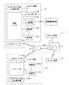
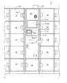
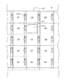
次に、本発明のロッカーシステムの実施形態を図面を参照して説明する。図1は本発明の実施形態のロッカーシステムの構成例を示すブロック図、図2は実施形態のロッカーシステムにおける第1タイプのロッカー装置1の外観正面図、図3は実施形態のロッカーシステムにおける第2タイプのロッカー装置2の外観正面図である。このロッカーシステムは、第1タイプのロッカー装置1,1,…、第2タイプのロッカー装置2,2,…、無線LANシステム3とで構成されている。
Next, an embodiment of the locker system of the present invention will be described with reference to the drawings. FIG. 1 is a block diagram showing a configuration example of a locker system according to an embodiment of the present invention, FIG. 2 is an external front view of a first
図2に示す第1タイプのロッカー装置1はICカードCdによりロッカーを利用できる電子マネー対応機であり、制御ユニット11を有しその両側及び下側にそれぞれ複数のロッカーボックス12が配置されている。また、本発明の特徴としてロッカー装置1の上部にはLANコンバータ13が配設されている。制御ユニット11内には、利用者に情報を表示するLCD表示器11a、ICカードCdからの電波を受信してICカードCdに対してデータの読み書きを行うカードリーダ/ライター11bを備えており、この集中制御装置11の前面には、LCD表示器11aの表示画面11a1、ICカードCdをタッチするカード操作部11b1が配設されている。また、硬貨を投入するための硬貨投入口111、硬貨により利用したときに暗証番号を記したレシートを排出するためのレシート出口112等が配設されている。各ロッカーボックス12は、ロッカー扉121の内部に制御ユニット11からの制御信号に基づいてロッカー扉121を施解錠する錠装置12a等を備えている。
The first
図3に示す第2タイプのロッカー装置2は硬貨のみでロッカーを利用するいわゆるコインロッカーを一部改造したものであり、複数のロッカーボックス22を配置したものである。各ロッカーボックス22は錠装置22aを備えており、この錠装置22aは、コインの投入によりキーを回動してロッカー扉221を解錠するものである。なお、このロッカー装置2の各キーには、対応するロッカーボックス22のロッカー番号と共に当該ロッカー装置2が設置されている場所(ロケーション)に対応するロケーション番号が記されている。ロッカー装置2はコンピュータ21を備えており、各錠装置22aはこのコンピュータ21に接続されている。また、ロッカー装置2の略中央位置にはコンピュータ21に接続されたLCD表示器21aが配設されている。さらに、本発明の特徴としてロッカー装置2の上部にはLANコンバータ23が配設されている。なお、コンピュータ21は各ロッカーボックス22における空き状態、使用状態、コインカウントのデータを管理する。
The second
図1に示すように、第1タイプのロッカー装置1において、制御ユニット11には、LCD表示器11a、データ通信部11c、LANコンバータ13、各ロッカーボックス12の各錠装置12aがそれぞれ接続されている。前記カードリーダ/ライター11bはデータ通信部11cを介して制御ユニット11に接続されている。なお、データ通信部11cは無線電話回線を介し管理センター等との間でデータの授受を行うこともできる。
As shown in FIG. 1, in the first
制御ユニット11は、LCD表示器11aへの表示データの出力と、このLCD表示器11aのタッチパネルの操作状態の検出を行う。また、制御ユニット11は、カードリーダ/ライター11bからのデータの入力及び出力を行う。また、制御ユニット11は、錠装置12aの施解錠の制御を行う。さらに、制御ユニット11は、LANコンバータ13を介して無線LANシステム3のアクセスポイント31との間で無線通信を行い各種のデータの授受を行う。そして、制御ユニット11は後述の制御プログラムに基づいてロッカー装置1の制御を行う。
The
第2タイプのロッカー装置2において、コンピュータ21には、LCD表示器21a、LANコンバータ23、各ロッカーボックス22の各錠装置22aがそれぞれ接続されている。コンピュータ21は、LCD表示器21aへの表示データの出力と、このLCD表示器21aのタッチパネルの操作状態の検出を行う。また、コンピュータ21は、錠装置22aにおける施解錠の状態を検出し、各ロッカーボックス22の利用状況を管理する。さらに、コンピュータ21は、LANコンバータ23を介して無線LANシステム3のアクセスポイント31との間で無線通信を行い各種のデータの授受を行う。
In the second
無線LANシステム3は複数のアクセスポイント31を有し、各アクセスポイント31間で無線でデータの授受を行う。また、各ロッカー装置1,2の各LANコンバータ13,23には、それぞれ固有のIPアドレスが設定されている。これにより各ロッカー装置1,2の間で送信元を認識しながらデータの授受を行うことができる。また、図1に省略して図示した第2タイプのロッカー装置2のようにそのコンピュータ(図示せず)を無線LANシステム3のハブ32に有線で接続してデータの授受を行うこともできる。
The
第1タイプのロッカー装置1の制御ユニット11、第2タイプのロッカー装置2のコンピュータ21は、自機のロケーション番号を有している。そして、各ロッカーボックス12,22の利用状況(利用中、空き)を管理し、この利用状況のデータを記憶するとともに、他のロッカー装置1,2の利用状況を示す利用情報もそのロケーション番号と共に記憶している。また、自機の利用状況が変化すると、その変化した利用状況を示す利用情報を送信する。さらに、他のロッカー装置1,2に対する予約が発生すると予約情報を送信する。予約情報をを受信したロッカー装置1,2は、予約情報により予約されたロッカーボックスを予約状態とするとともに、この予約状態を含む利用状況の利用情報を他のロッカー装置1,2に送信する。このように、各制御ユニット11、コンピュータ21は、自機の状態が変化すると逐一その利用情報を他のロッカー装置1,2に送信する。
The
ここで、第1タイプのロッカー装置1において、ロッカーボックス12が空き状態のときは、該ロッカーボックス12の錠装置12aは解錠状態となっており、このロッカーボックス12に荷物を預け入れてロッカー扉121を閉めると、錠装置12aは仮施錠状態となる。そして、ICカードCdをカード操作部11b1にタッチしてそのID情報(利用者ID情報)の認証と料金の引き落としが行われると、錠装置12aは本施錠される。また、第2タイプのロッカー装置2は、ロッカーボックス22が空き状態のときは、錠装置22aはキー操作できる状態となっており、所定の料金(コイン)を投入してキー操作すると錠装置22aが施錠できるようになっている。
Here, in the first
そこで、前記のようにロッカーボックスを予約状態とするとき、例えば次のようにする。第1タイプのロッカー装置1においては、予約情報を受信したときから予約されたロッカーボックス12に対応する錠装置12aを一定時間だけ仮施錠状態とする。そして、カード操作部11b1でICカードがタッチされ、そのID情報(利用者ID情報)が予約したときのID情報と一致した場合に、その錠装置12aの仮施錠を解除し、そのロッカーボックス12を利用可能とする。
Therefore, when the locker box is reserved as described above, for example, the following is performed. In the first
また、第2タイプのロッカー装置2においては、予約情報を受信したときから予約されたロッカーボックス22に対応する錠装置22aで一定時間だけキー操作ができない状態とする。そして、LCD表示器21aのタッチパネルの操作により、ICカードCdのID情報(カードに記されているID情報)が入力され、そのID情報が予約したときのID情報と一致した場合に、その錠装置22aをキー操作ができる状態とし、、そのロッカーボックス22を利用可能とする。
Further, in the second
また、このような予約したロッカーボックスの利用時の手順等は、予約したロッカー装置1においてそのガイダンスを表示するようにしてもよい。なお、予約状態は所定時間(例えば5分等)が経過すると解除される。
In addition, the procedure for using the reserved locker box may be displayed on the reserved
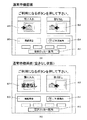
図4〜図6は第1タイプのロッカー装置1におけるLCD表示器11aの画面の表示例を示す図であり、第2タイプのロッカー装置2におけるLCD表示器21aの表示も略同様である。図4は待機状態の画面であり、図4(A) は通常の待機画面の例を示し、図4(B) はロッカーボックス12の空き無し状態の画面の例を示している。この待機画面では、「預け入れ」、「取り出し」、「残高照会」、「ご利用案内」、「空きロッカー案内」とそれぞれ記された画面ボタンB1、B2、B3、B4、B5が表示される。図4(B) のように空き無しの場合には、「預け入れ」のボタンB1には「空きなし」と表示され、このボタンB1の操作は無効となる。
4-6 is a figure which shows the example of a display of the
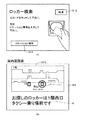
図4の待機画面で、「空きロッカー案内」のボタンB5を操作すると、図5(A) の案内図画面に切り替わる。この案内図画面には、当該ロッカーシステムが設置されている駅構内等の施設の案内地図MP1が表示される。なお、この例では、当該表示を行っているロッカー装置1が施設の2階に配置されているので、この2階の案内地図MP1が表示される。さらに、この案内図画面では、現在地マークP1、ロッカー装置1,2の位置を示すロッカーマークR1,R2,R3が表示される。そして、このロッカーマークR1,R2,R3の脇にそのロッカー装置の利用状況を示す「○」、「×」、「△」の利用状況マークRS1,RS2,RS3が表示される。この利用状況マークRS1の「○」は「充分空き有り」、利用状況マークRS2の「×」は「空き無し」、利用状況マークRS3の「△」は「少し空き有り」の各利用状況を示している。なお、駐車場のように「満」、「空」で表示してもよい。
When the “empty locker guidance” button B5 is operated on the standby screen of FIG. 4, the screen is switched to the guidance map screen of FIG. On this guide map screen, a guide map MP1 of a facility such as a station premises where the locker system is installed is displayed. In this example, since the
すなわち、現在操作しているロッカー装置1は空き無しの状態であり、現在地マークP1と共に利用状況マークRS1により空き無しの状態で表示されている。そこで、ロッカーマークR2またはR3の位置を指で触ると(タッチすると)、図5(B) の詳細利用状況画面に切り替わる。この詳細利用状況画面では、対応するロッカー装置1または2(この例ではロッカー装置1)のロッカーボックスの口数分のレイアウトを示す略図とともに、利用状態を示すロッカーガイド図GRが表示される。また、このロッカーガイド図GRの下には個々のロッカーボックスの利用状態、「使用中」、「使用中別途保管対称」、「空き」及び「利用不可」を色等で区別する索引欄Tが表示され、さらに、その下に、「戻る」、「予約」とそれぞれ記された画面ボタンB10、B11が表示される。「戻る」の画面ボタンB10が押下されると図5(A) の画面に戻り、「予約」の画面ボタンB11が押下されると、指定したロッカーボックスの予約を行うことができる。
That is, the
また、図5(A) の案内地図MP1の下には、「終了」、「1階」、「3階」、「検索」とそれぞれ記された画面ボタンB6、B7、B8、B9が表示される。「終了」の画面ボタンB6が押下されると図4の画面(待機状態)に戻り、「1階」の画面ボタンB7または「3階」の画面ボタンB8が押下されると、それぞれ1階または3階の案内図画面に切り替わる。また、「検索」の画面ボタンB9は利用者が預け入れたロッカーを検索する時に操作するものであり、この画面ボタンB9を押下すると、図6(A) の画面に切り替わる。 Further, screen buttons B6, B7, B8, and B9 labeled “END”, “1st floor”, “3rd floor”, and “Search” are displayed below the guidance map MP1 in FIG. The When the “end” screen button B6 is pressed, the screen returns to the screen of FIG. 4 (standby state), and when the “first floor” screen button B7 or the “third floor” screen button B8 is pressed, respectively, Switch to the 3rd floor guide map screen. The “search” screen button B9 is operated when searching for lockers deposited by the user. When the user presses this screen button B9, the screen is switched to the screen shown in FIG.
この図6(A) では、「ICカードをタッチして下さい。」、「又はロケーション番号を入力して下さい。」の案内が表示されるとともに、「取消」、「ロケーション番号」とそれぞれ記された画面ボタンB12、B13が表示される。そしてICカードCdを前記カード操作部11b1にタッチすると、そのID情報が読み取られ、当該ロッカーシステムにおいて正規に預け入れられたものと判断されると、例えば図6(B) の案内図画面が表示される。この例では、預け入れたロッカーが第1タイプのロッカー装置1であって、そのロッカー装置1の場所を、案内地図MP1とロッカーマークを「○」印で囲った案内マークGMにより案内し、さらにメッセージMにより案内している。また、第2タイプのロッカー装置2に荷物を預け入れた利用者は、「ロケーション番号」の画面ボタン13を押下し、所定の入力画面によりキーに記されているロケーション番号を入力する。この場合、正規のロケーション番号であれば図6(B) と同様な別のロッカー装置2を案内する案内図画面が表示される。
In this Fig. 6 (A), the guidance “Please touch IC card” or “Enter location number” is displayed, and “Cancel” and “Location number” are written respectively. The screen buttons B12 and B13 are displayed. When the IC card Cd is touched on the card operation unit 11b1, the ID information is read, and if it is determined that the locker system has been properly deposited, for example, a guide map screen shown in FIG. 6B is displayed. The In this example, the locker deposited is the first
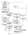
次に図7のフローチャートに基づいて、第1タイプのロッカー装置1における制御ユニット11の制御動作を説明する。先ず、ステップS1で待機状態とする。この待機状態では図4の画面を表示する。次に、ステップS2で、「空きロッカー案内」のボタンB5が押下されたか判定し、押下されなければステップS3で、預け入れや取り出し、利用情報の送信等のその他の処理を行ってステップS1に戻る。「空きロッカー案内」のボタンB5が押下されると、ステップS4で、例えば図5(A) のような現在のフロアの案内図画面を表示し、ステップS5に進む。
Next, based on the flowchart of FIG. 7, the control operation of the
以下、ステップS5、S6、S7、S8は図5(A) における画面操作に応じた処理であり、ステップS5で、案内図画面上で希望ロッカー位置(R1,R2,R3等)がタッチされると、ステップS5a以降の処理を行い、ステップS6で他のフロアの選択(例えば「1階」のボタンB7、「3階」のボタンB8の押下)があればステップS6a以降の処理を行う。また、ステップS7で「検索」のボタンB9の押下があれば、ステップS71以降の処理を行う。さらに、ステップS8、ステップS8aの処理で所定時間内に「終了」のボタンB6が押下されまでは、図5(A) の画面表示を続け、所定時間内に何の操作もなければステップS1に戻る。 Hereinafter, steps S5, S6, S7, and S8 are processes corresponding to the screen operation in FIG. 5A, and the desired locker position (R1, R2, R3, etc.) is touched on the guide map screen in step S5. Then, the processing after step S5a is performed, and if there is another floor selection (for example, pressing of the “first floor” button B7 or the “third floor” button B8) in step S6), the processing after step S6a is performed. If the “search” button B9 is pressed in step S7, the processing from step S71 onward is performed. Further, if the “End” button B6 is pressed within the predetermined time in the processing of Step S8 and Step S8a, the screen display of FIG. 5A is continued, and if there is no operation within the predetermined time, the process goes to Step S1. Return.
ステップS5で案内図画面上で希望ロッカー位置がタッチされれると、ステップS5aで、例えば図5(B) のような詳細利用状況画面を表示し、ステップS5bに進む。ステップS5bでは、例えば図5(B) の画面でロッカーボックスが選択されて「予約」のボタンB11が押下されたか判定し、押下されれば、ステップS5cでICカードCdのタッチを促す表示を行う。そして、ステップS5d及びステップS5eの処理で所定時間内にICカードCdのタッチがあれば、ステップS5fで予約対象の該当するロッカー装置に対して予約情報を送信し、ステップS5gに進む。この予約情報を受信したロッカー装置は、一定時間内は、予約により登録されたICカード以外ではその予約されたロッカーボックスへの預けいれを不可とする。また、所定時間内にICカードCdのタッチが無ければ、ステップS1に戻る。なお、ステップS5b、ステップS5g及びステップS5hの処理で所定時間内に、「予約」のボタンB11の押下、または図示しない「終了」のボタンの押下が無ければステップS1に戻る。 When the desired locker position is touched on the guide map screen in step S5, a detailed usage status screen such as that shown in FIG. 5B is displayed in step S5a, and the process proceeds to step S5b. In step S5b, for example, it is determined whether a locker box has been selected on the screen of FIG. 5B and the “reservation” button B11 has been pressed. If so, a display prompting the user to touch the IC card Cd is performed in step S5c. . If the IC card Cd is touched within the predetermined time in the processes of step S5d and step S5e, the reservation information is transmitted to the corresponding locker device to be reserved in step S5f, and the process proceeds to step S5g. The locker device that has received the reservation information cannot deposit the reserved locker box other than the IC card registered by the reservation for a certain period of time. If the IC card Cd is not touched within a predetermined time, the process returns to step S1. Note that if the “Reservation” button B11 is not pressed or the “End” button (not shown) is not pressed within a predetermined time in the processing of Step S5b, Step S5g and Step S5h, the process returns to Step S1.
ステップS6で他のフロアが選択されると、ステップS61で図5(A) と同様な他のフロアの案内図画面を表示し、ステップS5に戻る。 When another floor is selected in step S6, a guide map screen of another floor similar to FIG. 5A is displayed in step S61, and the process returns to step S5.
ステップS7で「検索」のボタンB9が押下されると、ステップS7aで、図6(A) の表示を行って、ICカードCdのタッチを促す表示及びロケーション番号の入力を促す表示を行う。そして、ステップS7b及びS7cで所定時間内にICカードCdのタッチ、またはロケーション番号の入力があれば、ステップS7dに進む。所定時間内にICカードCdのタッチかロケーション番号の入力が無ければステップS1に戻る。 When the “search” button B9 is pressed in step S7, the display shown in FIG. 6A is performed in step S7a, and the display prompting the IC card Cd to be touched and the display prompting the input of the location number are performed. If the IC card Cd is touched or the location number is input within a predetermined time in steps S7b and S7c, the process proceeds to step S7d. If the IC card Cd is not touched or the location number is not input within the predetermined time, the process returns to step S1.
ステップS7dでは、ICカードCdから読み取ったID情報(ロッカーID情報)または入力されたロケーション番号(ロッカーID情報)に対応するロッカー装置を検索し、ステップS7eで該当するロッカー装置が有ったかを判定する。該当するロッカー装置が有れば、ステップS7fでそのロッカー装置に対応して例えば図6(B) のように案内図とロッカー装置の位置を表示し、一定時間後にステップS1に戻る。該当するロッカー装置が無ければ、ステップS7gで「荷物は預かっていません」等のエラーメッセージを表示し、ステップS1に戻る。 In step S7d, a locker device corresponding to the ID information (locker ID information) read from the IC card Cd or the input location number (locker ID information) is searched, and it is determined whether there is a corresponding locker device in step S7e. To do. If there is a corresponding locker device, the guide map and the position of the locker device are displayed corresponding to the locker device in step S7f, for example, as shown in FIG. 6B, and the process returns to step S1 after a predetermined time. If there is no corresponding locker device, an error message such as “no luggage is left” is displayed in step S7g, and the process returns to step S1.
図8は第2タイプのロッカー装置2におけるコンピュータ21の制御動作を示すフローチャートである。このフローチャートは、ステップS5aからステップS5に戻る点、ステップS7a、S7b、S7dにおいてICカードに対する処理を行わない点で、図7の処理と異なり、その他の点は図7の処理(第1タイプのロッカー装置1の処理)と同様である。すなわち、図示は省略するが、第2タイプのLCD表示器21aにおける表示例は図4〜図6と略同様である。図4に対応する待機画面ではボタンB1〜B4は表示されない。また、図5に対応する画面では、「予約」のボタンB11は表示されない。さらに、図6に対応する画面ではICカードに対応する表示は行われない。その他は第1タイプのロッカー装置1と同様である。
FIG. 8 is a flowchart showing the control operation of the
以上の実施形態では、制御ユニット11、コンピュータ21が「制御手段」に相当し、LCD表示器11a,21aが「操作ディスプレイ」に相当する。また、無線LANシステム3が「ネットワーク」に相当し、LANコンバータ13,23が「通信手段」に相当する。
In the above embodiment, the
また、図5(A) に示す案内図画面の案内地図MP1及びロッカーマークR1,R2,R3が「他のロッカー装置の配置図」に相当し、「○」、「×」、「△」の利用状況マークRS1,RS2,RS3が「他のロッカー装置の利用状況」に相当する。なお、この実施形態では「他のロッカー装置の配置図」と「他のロッカー装置の利用状況」とを、共に関連付けて表示しているので、きわめて解りやすい表示となっているが、、他のロッカー装置の利用状況は表示しないで他のロッカー装置の配置図(例えば案内地図MP1とロッカーマークR1,R2,R3)だけを表示するようにしてもよい。また、他のロッカー装置の配置図は表示しないて、文章等により他のロッカー装置の利用状況だけを表示するようにしてもよい。また、音声での案内を付加させてもよい。 Further, the guide map MP1 and the locker marks R1, R2, R3 on the guide map screen shown in FIG. 5 (A) correspond to “arrangements of other locker devices”, and “○”, “×”, “△” Usage status marks RS1, RS2, and RS3 correspond to “usage status of other locker devices”. In this embodiment, the “arrangement diagram of other locker devices” and the “usage status of other locker devices” are displayed in association with each other, so the display is extremely easy to understand. You may make it display only the arrangement plan (for example, guidance map MP1 and locker mark R1, R2, R3) of other locker devices, without displaying the use situation of a locker device. In addition, the layout of other locker devices may not be displayed, and only the usage status of the other locker devices may be displayed by text or the like. Further, voice guidance may be added.
また、図5(B) に示すロッカーガイド図GRが「ロッカーボックスの詳細利用状況」(請求項5)に相当する。また、ICカードCdのID情報、キーに記されたロケーション番号が、「利用中のロッカーボックスに対応するロッカーID情報」(請求項3)に相当する。そして、このID情報またはロケーション番号により、預け入れたロッカーボックスの場所(ロケーション)を容易に確認できるので、利便性がきわめて高くなる。特に、他のロッカー装置で予約した場合、預け入れたロッカーボックスのロケーションは覚えにくいので、そのロッカー装置の配置図を確認できることできわめて利便性が高いシステムとなる。 Further, the rocker guide diagram GR shown in FIG. 5B corresponds to “detailed usage status of the locker box” (claim 5). The ID information of the IC card Cd and the location number written on the key correspond to “locker ID information corresponding to the locker box being used” (claim 3). Since the location (location) of the deposited locker box can be easily confirmed by this ID information or location number, the convenience is extremely high. In particular, when making a reservation with another locker device, it is difficult to remember the location of the locker box that has been deposited, so it is possible to confirm the layout of the locker device, which makes the system extremely convenient.
また、複数のロケーションに配置されている任意のロッカー装置において、他のロッカー装置の空きロッカーボックスの有無とそのロッカー装置の場所を容易に確認することができるので、利便性がきわめて高いシステムとなる。 In addition, in an arbitrary locker device arranged at a plurality of locations, the presence or absence of an empty locker box of another locker device and the location of the locker device can be easily confirmed, resulting in an extremely convenient system. .
また、実施形態では、例えば図5(B) 詳細利用状況画面においてロッカーボックスの配置(レイアウト)とロッカーボックスのサイズをそのまま表示しているので、空きロッカーボックスが上段、中段、下段のどこにあるのか、どのサイズのロッカーボックスが空いているのかが一目で確認できる。ただし、表示画面のサイズによっては、空きロッカーボックスの個数を数字等で表示するだけでも、ある程度の詳細は把握することができる。 In the embodiment, for example, the arrangement (layout) of the locker box and the size of the locker box are displayed as they are on the detailed usage status screen in FIG. 5B, so where the empty locker boxes are located in the upper, middle, and lower stages. , You can see at a glance what size locker box is available. However, depending on the size of the display screen, it is possible to grasp a certain level of detail simply by displaying the number of empty locker boxes as numbers.
また、実施形態では、預け入れたロッカー装置の場所も確認することができるので、迷わず荷物を取り出すことができる。 In the embodiment, since the location of the deposited locker device can also be confirmed, the package can be taken out without hesitation.
さらに、実施形態では、ICカードにより空きロッカーボックスを所定時間予約できるので、見つけた空きロッカーボックスの位置に行くまでに他者に利用されてしまうことを防止できる。 Furthermore, in the embodiment, an empty locker box can be reserved for a predetermined time by using an IC card, so that it is possible to prevent the empty locker box from being used by another person before going to the position of the found empty locker box.
以上の実施形態では、第1タイプのロッカー装置1と第2タイプのロッカー装置2とを混在させたシステムについて説明したが、空きロッカーボックスを表示して容易に確認できるような機能については、何れか一方のタイプのみでもよい。
In the above embodiment, the system in which the first
また、実施形態では、ロッカー装置で利用状況が変化した時に利用情報を通信するようにしているが、各ロッカー装置が定期的に通信を行って利用情報を取得するものでもよい。 In the embodiment, the usage information is communicated when the usage status changes in the locker device, but each locker device may periodically communicate to acquire the usage information.
また、ネットワークが無線LANの場合について説明したが、有線のLANであってもよい。 Moreover, although the case where the network is a wireless LAN has been described, a wired LAN may be used.
また、実施形態では、ID情報入力手段としてリーダ/ライターを使用しているので、使用ロッカーボックスのID情報をICカードに書き込ませる方式でもよい。この場合は、ネットワーク接続されていない異なるロケーションにても該当ロッカーボックスを案内することができる。 In the embodiment, since the reader / writer is used as the ID information input means, a method of writing the ID information of the used locker box on the IC card may be used. In this case, the corresponding locker box can be guided to different locations not connected to the network.
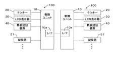
図9は本発明の第2の実施形態のロッカーシステムのロッカー装置の外観正面図である。このロッカー装置100は貴重品ボックスの例であり、例えばゴルフ場などの施設に複数設置されるものである。また、この実施形態ではID情報として手の中指の静脈パターンを用いるものである。このロッカー装置100は、中央の操作部4とその周囲に複数のロッカーボックス5を配置したものである。
FIG. 9 is an external front view of the rocker device of the rocker system according to the second embodiment of the present invention. The
操作部4には、制御手段としての制御ユニット10、ボックス番号を入力するためのテンキー20、利用者等に入力指示や案内等を表示する出力手段としてのLCD表示器30、利用者が手を当てることで中指の静脈パターンを入力して静脈パターンを認証するための静脈認証装置40が配設されている。また、各ロッカーボックス5は、ロッカー扉5aの内部に制御ユニット10からの制御信号に基づいてロッカーボックス5を施解錠する錠装置51を備えている。
The
図10は第2の実施形態のロッカーシステムの要部ブロック図であり、このロッカーシステムは2台のロッカー装置100,100を接続したものである。制御ユニット10には、前記のテンキー20、LCD表示器30、静脈認証装置40、錠装置51がそれぞれ接続されている。また、2台のロッカー装置の各制御ユニット10は通信手段としてのインターフェース10aを備えており、このインターフェース10aを介して互いにRS232C等の有線で接続されている。そして、各制御ユニット10に登録された静脈パターン(ID情報)を違いに送受信して両者で共有するようになっている。なお、各ロッカー装置100は自機のロッカー装置番号を有している。
FIG. 10 is a principal block diagram of the locker system according to the second embodiment, and this locker system is obtained by connecting two
以上の構成により次のように利用する。使用中のロッカーボックスはLED等が点灯しているので、点灯していないロッカーボックスを選び、ロッカー扉5aに明示されているボックス番号をテンキー20から入力し、静脈認証装置40に手(中指)を当てて静脈パターンを登録する。このとき、静脈認証装置40は静脈パターンを読み取り制御ユニット10はその静脈パターンを入力されたボックス番号に対応させて記憶(登録)する。
The above configuration is used as follows. Since the LED etc. is lit for the locker box in use, select the locker box that is not lit, enter the box number specified on the
静脈パターン及びボックス番号が登録されると、そのロッカーボックスのロッカー扉が解錠されるので、利用者は貴重品等を預け入れ、ロッカー扉を閉めるとその錠装置51が施錠される。また、制御ユニット10は、この登録が済むと、その静脈パターンとボックス番号及び当該ロッカー装置の番号の情報を一組にして、他のロッカー装置の制御ユニット10に通信する。他のロッカー装置で登録が行われた場合には、静脈パターンとボックス番号及び当該ロッカー装置の番号の情報の組が送信されてくるので、この情報を他のロッカー装置における情報として記憶する。
When the vein pattern and the box number are registered, the locker door of the locker box is unlocked. Therefore, when the user deposits valuables and closes the locker door, the
取り出すときは、静脈認証装置40から静脈パターンを入力すると、制御ユニット10は静脈認証装置40で読み取った静脈パターンに当該ロッカー装置に登録されているものかを判断し、登録されているものであれば対応するボックス番号の錠装置51を解錠する。読み取った静脈パターンが当該ロッカー装置に登録されたものでなければ、他のロッカー装置に登録されたものであるかを判断する。他のロッカー装置に登録されたものでれば、LCD表示器30に、例えば「別のロッカー装置に預けてあります。」等の表示を行って該当のロッカー装置番号を案内する。また、他のロッカー装置に登録されたものでもなければ、エラー表示等を行う。なお、この取り出し時にはボックス番号は入力しなくてもよい。
When the vein pattern is input from the
図11は第2の実施形態における制御ユニット10の制御に係るフローチャートである。制御ユニット10は、先ず、ステップS11で、LCD表示器30に「取り出し及び預け入れ時の操作をガイドする表示を行い、ステップS12,S13で、預け入れ時のボックス番号の入力と取り出し時の静脈パターンの入力の有無を監視する。そして、ボックス番号の入力があればステップS14以降で預け入れ及び登録の処理を行い、静脈パターンの入力があればステップS21以降で取り出しの処理を行う。
FIG. 11 is a flowchart relating to the control of the
ステップS12でボックス番号が入力されると、ステップS14で、入力されたボックス番号のロッカーボックスが空きであるか否かを判定し、空きでなければステップS15で「使用中です」等のエラー表示を行ってステップS11に戻る。空きでなければ、ステップS16で静脈パターンの入力を受け付け、静脈パターンが入力されると、ステップS17でその静脈パターンとボックス番号を対応付けて当該ロッカー装置に登録し、ステップS18でボックス番号に対応するロッカーボックスの錠装置51を解錠し、ステップS19でロッカーボックスの扉の開閉動作を監視する。扉が開閉されれば、ステップS20で錠装置51を施錠してステップS26に進む。そして、ステップS26で、新たに登録された静脈パターンの情報を当該ロッカー装置のロッカー装置番号と共に登録情報として他のロッカー装置100に送信する。
When the box number is input in step S12, it is determined in step S14 whether or not the locker box of the input box number is empty. If it is not empty, an error display such as “in use” is displayed in step S15. To return to step S11. If it is not empty, the input of the vein pattern is accepted in step S16. When the vein pattern is input, the vein pattern and the box number are associated with each other and registered in the locker device in step S17, and the box number is associated in step S18. The locker
ステップS13で静脈パターンが入力されると(認識されると)、ステップS21で、入力された静脈パターンが当該ロッカー装置のものとして登録されているかを判定し、登録されていなければステップS27に進み、登録されていれば、ステップS22でその静脈パターンに対応するロッカーボックスの錠装置51を解錠し、ステップS23でロッカーボックスの扉の開閉動作を監視する。扉が開閉されれば、ステップS24で錠装置51を施錠するとともに、ステップS25でそのロッカーボックスの登録情報(ボックス番号及び静脈パターンの情報)を削除し、ステップS26に進む。ステップS26では、登録を削除した情報を新たな登録情報として他のロッカー装置100に送信する。
When a vein pattern is input (recognized) in step S13, it is determined in step S21 whether the input vein pattern is registered as that of the locker device. If not, the process proceeds to step S27. If registered, the
ステップS21で、入力された静脈パターンが当該ロッカー装置のものとして登録されていなければ、ステップS27で、その静脈パターンが他のロッカー装置のものとして登録されているを判定し、他のロッカー装置のものとして登録されていれば、ステップS28で、「他のロッカー装置に預かっています」等の他のロッカー装置への案内を表示し、ステップS11に戻る。他のロッカー装置にも登録されていなければ、ステップS29で「預かっておりません」等のエラー表示を行ってステップS11に戻る。 If the input vein pattern is not registered as that of the locker device in step S21, it is determined in step S27 that the vein pattern is registered as that of another locker device, and the other locker device's If registered as a thing, in step S28, a guide to another locker device such as “I keep it in another locker device” is displayed, and the process returns to step S11. If it is not registered in any other locker device, an error message such as “Not kept” is displayed in step S29 and the process returns to step S11.
以上の実施形態では、静脈パターンをID情報として利用しているが、暗証番号をID情報として用いるようにしてもよい。この場合には、利用開始時にボックス番号の後に暗証番号を入力することで、ボックス番号と暗証番号が対応つけて登録される。また、この場合も、暗証番号とボックス番号及び当該ロッカー装置の番号の情報を一組にして、複数のロッカー装置で授受を行い、この登録情報を共有することにより、他のロッカー装置に預けたものであれば、案内をすることができる。 In the above embodiment, the vein pattern is used as ID information. However, a personal identification number may be used as ID information. In this case, by inputting the password after the box number at the start of use, the box number and the password are registered in association with each other. In this case as well, the information on the PIN number, box number, and number of the locker device is paired, exchanged with a plurality of locker devices, and this registration information is shared to deposit with other locker devices. If it is something, you can give guidance.
また、この実施形態のロッカー装置(貴重品ボックス)でも、前記実施形態のようにICカードを利用してロッカーボックスを利用できるようにしてもよい。この場合は、ICカードのID情報をID情報として利用することができる。また、預け入れたロッカーボックスが他のロッカー装置の場合、音声等により案内するようにしてもよい。 In addition, the locker device (the valuable box) of this embodiment may be configured such that the locker box can be used using an IC card as in the above embodiment. In this case, the ID information of the IC card can be used as the ID information. Moreover, when the deposited locker box is another locker device, guidance may be provided by voice or the like.
1 第1タイプのロッカー装置
2 第2タイプのロッカー装置
3 無線LANシステム
Cd ICカード
11 制御ユニット(制御手段)
11a LCD表示器(操作ディスプレイ)
11b カードリーダ/ライター
12 ロッカーボックス
12a 錠装置
13 LANコンバータ(通信手段)
21 コンピュータ(制御手段)
21a LCD表示器(操作ディスプレイ)
22 ロッカーボックス
22a 錠装置
23 LANコンバータ(通信手段)
DESCRIPTION OF
11a LCD display (operation display)
11b Card reader /
21 Computer (control means)
21a LCD display (operation display)
22
Claims (7)
前記各ロッカー装置は、複数のロッカーボックスを管理する制御手段と、該制御手段に接続された操作ディスプレイと、前記ネットワークを介して他のロッカー装置との間で情報の通信を行う通信手段とを備え、
前記各ロッカー装置が、当該ロッカー装置の前記操作ディスプレイの操作により、他のロッカー装置に関する案内情報を表示することを特徴とするロッカーシステム。 A locker system in which a plurality of locker devices composed of a plurality of locker boxes are connected via a network,
Each locker device includes a control means for managing a plurality of locker boxes, an operation display connected to the control means, and a communication means for communicating information with other locker devices via the network. Prepared,
Each locker device displays guidance information about another locker device by operating the operation display of the locker device.
前記各ロッカー装置が、前記案内情報として他のロッカー装置の配置図を表示することを特徴とするロッカーシステム。 The locker system according to claim 1,
Each locker device displays a layout of another locker device as the guide information.
前記各ロッカー装置は、前記通信手段により他のロッカー装置における利用情報を取得し、利用中のロッカーボックスに対応するロッカーID情報が入力されると、前記操作ディスプレイに、該ロッカーID情報に対応するロッカーボックスを含むロッカー装置の位置を案内表示することを特徴とするロッカーシステム。 The locker system according to claim 2,
Each locker device acquires usage information in another locker device by the communication means, and when locker ID information corresponding to a locker box being used is input, the locker ID information corresponds to the locker ID information on the operation display. A locker system, characterized by displaying a position of a locker device including a locker box.
前記各ロッカー装置が、前記通信手段により他のロッカー装置における利用情報を取得し、当該ロッカー装置の前記操作ディスプレイに、該利用情報により他のロッカー装置の利用状況を表示することを特徴とするロッカーシステム。 The locker system according to claim 1,
Each locker device acquires usage information in another locker device by the communication means, and displays the usage status of the other locker device on the operation display of the locker device based on the usage information. system.
前記ロッカー装置は、前記操作ディスプレイに前記利用状況として各ロッカーボックスの詳細利用状況を表示し、該表示された詳細利用状況の中から空きロッカーボックスの予約が選択されると、当該ロッカー装置から該予約されたロッカーボックスに対応するロッカー装置に対して予約情報を通知し、該通知されたロッカー装置が該予約された空きロッカーボックスを一時的に予約状態とすることを特徴とするロッカーシステム。 The locker system according to claim 4,
The locker device displays a detailed usage status of each locker box as the usage status on the operation display, and when reservation of an empty locker box is selected from the displayed detailed usage status, A locker system, wherein reservation information is notified to a locker device corresponding to a reserved locker box, and the notified locker device temporarily places the reserved empty locker box in a reserved state.
前記ロッカー装置は、利用者ID情報の入力により前記空きロッカーボックスを一時的に予約状態とし、該予約状態とされたロッカーボックスに対応するロッカー装置は、予約状態で該利用者ID情報が入力されると該ロッカーボックスの予約状態を解除することを特徴とするロッカーシステム。 The locker system according to claim 5,
The locker device temporarily places the empty locker box in a reserved state by inputting user ID information, and the locker device corresponding to the reserved locker box receives the user ID information in the reserved state. Then, the locker system which cancels the reservation state of this locker box.
前記各ロッカー装置は、情報を出力する出力手段と、前記ネットワークを介して他のロッカー装置との間で情報の通信を行う通信手段とを備え、
前記各ロッカー装置は、前記通信手段により他のロッカー装置に登録されたID情報を取得し、当該ロッカー装置に登録されているID情報が入力されると該ID情報に対応するロッカーボックスを解錠し、他のロッカー装置に登録されているID情報が入力されると、該ID情報に対応するロッカーボックスを含むロッカー装置を前記出力手段により案内することを特徴とするロッカーシステム。 A locker device comprising a plurality of locker boxes and a control means for controlling the unlocking of the locker box by comparing ID information registered corresponding to the locker box and the input ID information in one facility A locker system comprising a plurality of lockers connected to the lockers,
Each locker device includes output means for outputting information, and communication means for communicating information with other locker devices via the network,
Each locker device acquires ID information registered in another locker device by the communication means, and when the ID information registered in the locker device is input, the locker box corresponding to the ID information is unlocked When the ID information registered in another locker device is input, the locker system including the locker box corresponding to the ID information is guided by the output means.
Priority Applications (1)
| Application Number | Priority Date | Filing Date | Title |
|---|---|---|---|
| JP2008200547A JP5244493B2 (en) | 2008-06-13 | 2008-08-04 | Locker system |
Applications Claiming Priority (3)
| Application Number | Priority Date | Filing Date | Title |
|---|---|---|---|
| JP2008155152 | 2008-06-13 | ||
| JP2008155152 | 2008-06-13 | ||
| JP2008200547A JP5244493B2 (en) | 2008-06-13 | 2008-08-04 | Locker system |
Publications (2)
| Publication Number | Publication Date |
|---|---|
| JP2010020733A true JP2010020733A (en) | 2010-01-28 |
| JP5244493B2 JP5244493B2 (en) | 2013-07-24 |
Family
ID=41705522
Family Applications (1)
| Application Number | Title | Priority Date | Filing Date |
|---|---|---|---|
| JP2008200547A Active JP5244493B2 (en) | 2008-06-13 | 2008-08-04 | Locker system |
Country Status (1)
| Country | Link |
|---|---|
| JP (1) | JP5244493B2 (en) |
Cited By (9)
| Publication number | Priority date | Publication date | Assignee | Title |
|---|---|---|---|---|
| JP2011233065A (en) * | 2010-04-30 | 2011-11-17 | Alpha Corp | Locker system |
| JP2014238644A (en) * | 2013-06-06 | 2014-12-18 | グローリー株式会社 | Locker device and control method thereof |
| CN105096024A (en) * | 2014-05-12 | 2015-11-25 | 河村电器产业株式会社 | Rack management system |
| JP2017010814A (en) * | 2015-06-23 | 2017-01-12 | 富士通コンポーネント株式会社 | Receiving device and position specification system |
| JP6319781B1 (en) * | 2017-10-20 | 2018-05-09 | 株式会社バカン | Coin locker system |
| JP2018150715A (en) * | 2017-03-13 | 2018-09-27 | 株式会社熊平製作所 | Storage case system and control unit |
| WO2019230875A1 (en) * | 2018-06-01 | 2019-12-05 | Miyamoto Hirofumi | Baggage checking/reception device and backage checking/reception program |
| JP2021140565A (en) * | 2020-03-06 | 2021-09-16 | オムロン株式会社 | Facility use management system, facility use management method, and program |
| JP7442713B1 (en) | 2023-03-29 | 2024-03-04 | Kddi株式会社 | Information processing device, information processing method and program |
Families Citing this family (1)
| Publication number | Priority date | Publication date | Assignee | Title |
|---|---|---|---|---|
| JP5697767B1 (en) * | 2014-01-14 | 2015-04-08 | 基 小野田 | Valuables storage device |
Citations (3)
| Publication number | Priority date | Publication date | Assignee | Title |
|---|---|---|---|---|
| JPH0235281U (en) * | 1988-08-31 | 1990-03-07 | ||
| JP2006251921A (en) * | 2005-03-08 | 2006-09-21 | Nec Corp | Locker system, method, apparatus, and program, locker reservation terminal, ticket gate for transport facility, and locker |
| JP2006285658A (en) * | 2005-03-31 | 2006-10-19 | Fujimikku:Kk | Locker network system |
-
2008
- 2008-08-04 JP JP2008200547A patent/JP5244493B2/en active Active
Patent Citations (3)
| Publication number | Priority date | Publication date | Assignee | Title |
|---|---|---|---|---|
| JPH0235281U (en) * | 1988-08-31 | 1990-03-07 | ||
| JP2006251921A (en) * | 2005-03-08 | 2006-09-21 | Nec Corp | Locker system, method, apparatus, and program, locker reservation terminal, ticket gate for transport facility, and locker |
| JP2006285658A (en) * | 2005-03-31 | 2006-10-19 | Fujimikku:Kk | Locker network system |
Cited By (15)
| Publication number | Priority date | Publication date | Assignee | Title |
|---|---|---|---|---|
| JP2011233065A (en) * | 2010-04-30 | 2011-11-17 | Alpha Corp | Locker system |
| JP2014238644A (en) * | 2013-06-06 | 2014-12-18 | グローリー株式会社 | Locker device and control method thereof |
| CN105096024A (en) * | 2014-05-12 | 2015-11-25 | 河村电器产业株式会社 | Rack management system |
| JP2015214854A (en) * | 2014-05-12 | 2015-12-03 | 河村電器産業株式会社 | Rack management system |
| CN105096024B (en) * | 2014-05-12 | 2018-11-09 | 河村电器产业株式会社 | Rack management system |
| JP2017010814A (en) * | 2015-06-23 | 2017-01-12 | 富士通コンポーネント株式会社 | Receiving device and position specification system |
| JP2018150715A (en) * | 2017-03-13 | 2018-09-27 | 株式会社熊平製作所 | Storage case system and control unit |
| JP6319781B1 (en) * | 2017-10-20 | 2018-05-09 | 株式会社バカン | Coin locker system |
| WO2019077776A1 (en) * | 2017-10-20 | 2019-04-25 | 株式会社バカン | Coin-operated locker system |
| JP2019079092A (en) * | 2017-10-20 | 2019-05-23 | 株式会社バカン | Coin locker system |
| WO2019230875A1 (en) * | 2018-06-01 | 2019-12-05 | Miyamoto Hirofumi | Baggage checking/reception device and backage checking/reception program |
| JPWO2019230875A1 (en) * | 2018-06-01 | 2021-08-12 | 宮本 博文 | Baggage storage reception device and baggage storage reception program |
| JP7356418B2 (en) | 2018-06-01 | 2023-10-04 | 博文 宮本 | Baggage storage reception device and baggage storage reception program |
| JP2021140565A (en) * | 2020-03-06 | 2021-09-16 | オムロン株式会社 | Facility use management system, facility use management method, and program |
| JP7442713B1 (en) | 2023-03-29 | 2024-03-04 | Kddi株式会社 | Information processing device, information processing method and program |
Also Published As
| Publication number | Publication date |
|---|---|
| JP5244493B2 (en) | 2013-07-24 |
Similar Documents
| Publication | Publication Date | Title |
|---|---|---|
| JP5244493B2 (en) | Locker system | |
| JP4062680B2 (en) | Facility reservation method, server used for facility reservation method, and server used for event reservation method | |
| KR100960517B1 (en) | user authentication method of having used graphic OTP and user authentication system using the same | |
| CN105469508A (en) | Storage cabinet, mobile terminal and storage cabinet control method and system | |
| JP5639334B2 (en) | Goods storage device | |
| JP5380053B2 (en) | Locker device and control method thereof | |
| JP2005202580A (en) | Device status grasping system | |
| JP2010126913A (en) | Electronic lock device and locker equipment | |
| JP5639621B2 (en) | Important material management device | |
| JP5813938B2 (en) | Key management apparatus and key management method | |
| JP2022084381A (en) | Locker management system, locker device, and locker device management method | |
| JP6211810B2 (en) | Locker device and control method thereof | |
| JP4804846B2 (en) | Game medium rental system and game medium rental method | |
| JP2007102273A (en) | System of rental locker | |
| JP6802004B2 (en) | Key management device, key management system and key management method | |
| JP2011233065A (en) | Locker system | |
| JP6825742B1 (en) | Facility use management system, facility use management method, and program | |
| JP7083136B2 (en) | Important property management device | |
| JP5004458B2 (en) | Unlocking control system and unlocking control method for lending processor installed side by side in gaming machine | |
| JP2014238644A (en) | Locker device and control method thereof | |
| JP6111951B2 (en) | Rental locker device | |
| JP2004206516A (en) | Room management system and its device | |
| JP5469441B2 (en) | Locker equipment | |
| JP4184589B2 (en) | Locker equipment | |
| JP2020122310A (en) | Key management machine, key management system, and key management method |
Legal Events
| Date | Code | Title | Description |
|---|---|---|---|
| A621 | Written request for application examination |
Free format text: JAPANESE INTERMEDIATE CODE: A621 Effective date: 20110801 |
|
| A977 | Report on retrieval |
Free format text: JAPANESE INTERMEDIATE CODE: A971007 Effective date: 20130325 |
|
| TRDD | Decision of grant or rejection written | ||
| A01 | Written decision to grant a patent or to grant a registration (utility model) |
Free format text: JAPANESE INTERMEDIATE CODE: A01 Effective date: 20130402 |
|
| A61 | First payment of annual fees (during grant procedure) |
Free format text: JAPANESE INTERMEDIATE CODE: A61 Effective date: 20130408 |
|
| FPAY | Renewal fee payment (event date is renewal date of database) |
Free format text: PAYMENT UNTIL: 20160412 Year of fee payment: 3 |
|
| R150 | Certificate of patent or registration of utility model |
Free format text: JAPANESE INTERMEDIATE CODE: R150 Ref document number: 5244493 Country of ref document: JP Free format text: JAPANESE INTERMEDIATE CODE: R150 |
|
| R250 | Receipt of annual fees |
Free format text: JAPANESE INTERMEDIATE CODE: R250 |
|
| R250 | Receipt of annual fees |
Free format text: JAPANESE INTERMEDIATE CODE: R250 |
|
| R250 | Receipt of annual fees |
Free format text: JAPANESE INTERMEDIATE CODE: R250 |
|
| R250 | Receipt of annual fees |
Free format text: JAPANESE INTERMEDIATE CODE: R250 |
|
| R250 | Receipt of annual fees |
Free format text: JAPANESE INTERMEDIATE CODE: R250 |