JP2010020453A - Communication apparatus - Google Patents
Communication apparatus Download PDFInfo
- Publication number
- JP2010020453A JP2010020453A JP2008178881A JP2008178881A JP2010020453A JP 2010020453 A JP2010020453 A JP 2010020453A JP 2008178881 A JP2008178881 A JP 2008178881A JP 2008178881 A JP2008178881 A JP 2008178881A JP 2010020453 A JP2010020453 A JP 2010020453A
- Authority
- JP
- Japan
- Prior art keywords
- communication
- contactless card
- unit
- antenna
- card
- Prior art date
- Legal status (The legal status is an assumption and is not a legal conclusion. Google has not performed a legal analysis and makes no representation as to the accuracy of the status listed.)
- Granted
Links
- 238000004891 communication Methods 0.000 title claims abstract description 89
- 230000004913 activation Effects 0.000 claims description 15
- 238000001514 detection method Methods 0.000 claims description 3
- 230000003213 activating effect Effects 0.000 claims 1
- 238000005259 measurement Methods 0.000 abstract description 7
- 238000000034 method Methods 0.000 description 56
- 230000008569 process Effects 0.000 description 51
- 238000010248 power generation Methods 0.000 description 16
- 238000012545 processing Methods 0.000 description 12
- 230000010365 information processing Effects 0.000 description 7
- 238000010586 diagram Methods 0.000 description 4
- 230000004044 response Effects 0.000 description 4
- 230000006870 function Effects 0.000 description 3
- 239000003999 initiator Substances 0.000 description 3
- 238000005286 illumination Methods 0.000 description 2
- 230000002457 bidirectional effect Effects 0.000 description 1
- 230000005540 biological transmission Effects 0.000 description 1
- 230000001413 cellular effect Effects 0.000 description 1
- 238000006243 chemical reaction Methods 0.000 description 1
- 230000005674 electromagnetic induction Effects 0.000 description 1
- 239000000284 extract Substances 0.000 description 1
- 238000012986 modification Methods 0.000 description 1
- 230000004048 modification Effects 0.000 description 1
- 230000008520 organization Effects 0.000 description 1
- 238000007493 shaping process Methods 0.000 description 1
- 230000001960 triggered effect Effects 0.000 description 1
Images


Classifications
-
- G—PHYSICS
- G06—COMPUTING; CALCULATING OR COUNTING
- G06K—GRAPHICAL DATA READING; PRESENTATION OF DATA; RECORD CARRIERS; HANDLING RECORD CARRIERS
- G06K7/00—Methods or arrangements for sensing record carriers, e.g. for reading patterns
- G06K7/0008—General problems related to the reading of electronic memory record carriers, independent of its reading method, e.g. power transfer
-
- G—PHYSICS
- G06—COMPUTING; CALCULATING OR COUNTING
- G06K—GRAPHICAL DATA READING; PRESENTATION OF DATA; RECORD CARRIERS; HANDLING RECORD CARRIERS
- G06K7/00—Methods or arrangements for sensing record carriers, e.g. for reading patterns
- G06K7/10—Methods or arrangements for sensing record carriers, e.g. for reading patterns by electromagnetic radiation, e.g. optical sensing; by corpuscular radiation
- G06K7/10009—Methods or arrangements for sensing record carriers, e.g. for reading patterns by electromagnetic radiation, e.g. optical sensing; by corpuscular radiation sensing by radiation using wavelengths larger than 0.1 mm, e.g. radio-waves or microwaves
- G06K7/10118—Methods or arrangements for sensing record carriers, e.g. for reading patterns by electromagnetic radiation, e.g. optical sensing; by corpuscular radiation sensing by radiation using wavelengths larger than 0.1 mm, e.g. radio-waves or microwaves the sensing being preceded by at least one preliminary step
- G06K7/10128—Methods or arrangements for sensing record carriers, e.g. for reading patterns by electromagnetic radiation, e.g. optical sensing; by corpuscular radiation sensing by radiation using wavelengths larger than 0.1 mm, e.g. radio-waves or microwaves the sensing being preceded by at least one preliminary step the step consisting of detection of the presence of one or more record carriers in the vicinity of the interrogation device
-
- G—PHYSICS
- G06—COMPUTING; CALCULATING OR COUNTING
- G06K—GRAPHICAL DATA READING; PRESENTATION OF DATA; RECORD CARRIERS; HANDLING RECORD CARRIERS
- G06K7/00—Methods or arrangements for sensing record carriers, e.g. for reading patterns
- G06K7/10—Methods or arrangements for sensing record carriers, e.g. for reading patterns by electromagnetic radiation, e.g. optical sensing; by corpuscular radiation
- G06K7/10009—Methods or arrangements for sensing record carriers, e.g. for reading patterns by electromagnetic radiation, e.g. optical sensing; by corpuscular radiation sensing by radiation using wavelengths larger than 0.1 mm, e.g. radio-waves or microwaves
- G06K7/10198—Methods or arrangements for sensing record carriers, e.g. for reading patterns by electromagnetic radiation, e.g. optical sensing; by corpuscular radiation sensing by radiation using wavelengths larger than 0.1 mm, e.g. radio-waves or microwaves setting parameters for the interrogator, e.g. programming parameters and operating modes
- G06K7/10207—Methods or arrangements for sensing record carriers, e.g. for reading patterns by electromagnetic radiation, e.g. optical sensing; by corpuscular radiation sensing by radiation using wavelengths larger than 0.1 mm, e.g. radio-waves or microwaves setting parameters for the interrogator, e.g. programming parameters and operating modes parameter settings related to power consumption of the interrogator
Abstract
Description
本発明は、通信装置に関し、特に、非接触カードと近接通信を行う通信装置に関する。 The present invention relates to a communication device, and more particularly to a communication device that performs proximity communication with a contactless card.
近年、テレビジョン受像機(以下、TVと称する)をインターネットに接続し、従来パーソナルコンピュータなどで利用されていたオンラインショッピングを、TVで楽しむようにする利用方法が提案されている。 In recent years, there has been proposed a usage method in which a television receiver (hereinafter referred to as TV) is connected to the Internet so that online shopping, which has been conventionally used on personal computers, can be enjoyed on the TV.
この場合、TVのリモートコントローラに非接触カードの情報を読み取るカードリーダライタ(以下、カードR/Wと称する)を搭載することが考えられる。そして、ユーザは、例えば、非接触カードからなるクレジットカードをリモートコントローラに翳すだけで、暗証番号やカード番号などの入力操作を行うことなく、オンラインショッピングの決済の手続を簡単に行うことができるようになると考えられる。 In this case, it is conceivable that a card reader / writer (hereinafter referred to as a card R / W) that reads information on a contactless card is mounted on the TV remote controller. Then, for example, the user can easily carry out the online shopping settlement procedure without performing an input operation such as a personal identification number or a card number simply by holding a credit card made up of a contactless card over the remote controller. It is thought that it will become.
ところで、任意のタイミングでリモートコントローラに翳される非接触カードを確実に捕捉するためには、カードR/Wが、非接触カードを探索するために電磁波を周囲に発するポーリング処理を周期的に行う必要がある。しかし、ポーリング処理を常時行うようにした場合、リモートコントローラの電池の寿命が短くなり、電池交換を頻繁に行わなければならなくなる。例えば、リモートコントローラがアルカリ電池2本(容量4000mAh)により駆動され、カードR/Wの駆動電圧および駆動電流が、それぞれ1.9Vおよび100mAであると仮定した場合、4000÷1.9÷100=21時間しか電池の寿命が持続しないことになる。 By the way, in order to reliably capture a contactless card that is trapped by the remote controller at an arbitrary timing, the card R / W periodically performs a polling process that emits an electromagnetic wave to the surroundings in order to search for the contactless card. There is a need. However, when the polling process is always performed, the battery life of the remote controller is shortened and the battery must be frequently replaced. For example, assuming that the remote controller is driven by two alkaline batteries (capacity 4000mAh) and the drive voltage and drive current of the card R / W are 1.9V and 100mA respectively, 4000 ÷ 1.9 ÷ 100 = 21 hours only Battery life will not last.
そこで、近距離無線通信機器の状態を、アイドル動作状態、ターゲット動作状態、イニシエータ動作状態の3つの状態の間を周期的に遷移させるようにして、イニシエータ動作状態のときにのみポーリング処理を行うようにすることが提案されている(例えば、特許文献1参照)。この特許文献1に記載の発明を、上述したTVのリモートコントローラに適用することにより、ポーリング処理を行う時間を短縮し、消費電力を削減し、電池の寿命を延ばすことが可能になる。
Therefore, the state of the short-range wireless communication device is periodically changed between the three states of the idle operation state, the target operation state, and the initiator operation state, and the polling process is performed only in the initiator operation state. (For example, refer patent document 1). By applying the invention described in
しかしながら、特許文献1に記載の発明において、仮に、イニシエータ動作状態を全期間のうちの10%に設定し、他の動作状態における消費電力をゼロにしたとしても、上記の条件下において、リモートコントローラの電池の寿命は約10倍の210時間にしかならない。これは、現在一般的に使用されているTVのリモートコントローラの電池の寿命が約1〜2年であることを考えると、十分な長さであるとは言えない。
However, in the invention described in
本発明は、このような状況を鑑みてなされたものであり、非接触カードとの近接通信において消費する電力を低減できるようにするものである。 The present invention has been made in view of such a situation, and makes it possible to reduce power consumed in proximity communication with a contactless card.
本発明の一側面の通信装置は、アンテナと、前記アンテナを介して非接触カードと近接通信を行う第1の通信手段と、前記アンテナの近傍に設けられ、入射光量を検出する光検出手段と、前記入射光量が所定の閾値未満になった場合、前記第1の通信手段を起動する近接通信制御手段とを含み、電池により駆動される。 A communication apparatus according to an aspect of the present invention includes an antenna, a first communication unit that performs proximity communication with a contactless card via the antenna, and a light detection unit that is provided near the antenna and detects an incident light amount. And a proximity communication control unit that activates the first communication unit when the amount of incident light falls below a predetermined threshold value, and is driven by a battery.
前記近接通信制御手段には、前記第1の通信手段を起動した後、前記非接触カードとの近接通信が行われないまま所定の時間が経過した場合、前記第1の通信手段の動作を停止させ、前記入射光量が前記閾値を超えるまで、前記第1の通信手段を起動させないようにすることができる。 The proximity communication control means stops the operation of the first communication means when a predetermined time has passed without starting the proximity communication with the contactless card after starting the first communication means. The first communication unit can be prevented from being activated until the incident light amount exceeds the threshold value.
前記非接触カードから取得した情報を他の装置に送信する第2の通信手段をさらに設けることができる。 A second communication means for transmitting information acquired from the contactless card to another device can be further provided.
前記近接通信制御手段には、前記第2の通信手段を介して前記他の装置から所定の起動信号を受信した場合、前記第1の通信手段を起動させることができる。 When the proximity communication control unit receives a predetermined activation signal from the other device via the second communication unit, the first communication unit can be activated.
前記光検出手段は、入射する光を電力に変換し、前記電池を充電する光発電パネルにより構成することができる。 The light detection means can be constituted by a photovoltaic panel that converts incident light into electric power and charges the battery.
本発明の一側面においては、アンテナの近傍の入射光量が所定の閾値未満になった場合、前記アンテナを介して非接触カードと近接通信を行う第1の通信手段が起動される。 In one aspect of the present invention, when the amount of incident light in the vicinity of the antenna becomes less than a predetermined threshold, first communication means for performing proximity communication with the contactless card via the antenna is activated.
本発明の一側面によれば、非接触カードとの近接通信の制御を行うことができる。特に、本発明の一側面によれば、非接触カードとの近接通信において消費する電力を低減することができ、その結果、電池の寿命を延ばすことができる。 According to one aspect of the present invention, it is possible to control proximity communication with a contactless card. In particular, according to one aspect of the present invention, power consumed in proximity communication with a contactless card can be reduced, and as a result, battery life can be extended.
以下、図面を参照して本発明を適用した実施の形態について説明する。 Embodiments to which the present invention is applied will be described below with reference to the drawings.
図1は、本発明を適用した情報処理システムの一実施の形態を示すブロック図である。図1の情報処理システム1は、TV11、リモートコントローラ12、非接触カード13、および、決済サーバ14を含むように構成される。情報処理システム1は、オンラインショッピングなどのインターネット21を利用したサービスを、TV11により利用できるようにするシステムである。
FIG. 1 is a block diagram showing an embodiment of an information processing system to which the present invention is applied. The
TV11は、インターネット21に接続され、インターネット21を介して、決済サーバ14などの他の装置と通信することが可能である。
The TV 11 is connected to the Internet 21 and can communicate with other devices such as the
リモートコントローラ12は、アンテナ42およびTV11のアンテナ31を介して、TV11と双方向の無線通信を行い、TV11の遠隔操作を行う。
The
また、リモートコントローラ12は、非接触カード13の情報の読み書きを行う非接触カードリーダライタ(R/W)部52(図2)を内蔵し、各種の操作キーが設けられている操作面12Aに受信面が来るように、アンテナ41が設けられている。従って、非接触カード13をアンテナ41に翳すことにより、リモートコントローラ12と非接触カード13(非接触カードR/W部52)は、電磁誘導による近接通信(NFC(Near Field Communication))を行う。なお、近接通信とは、通信する装置どうしの距離が、数10cm以内となって可能となる通信を意味し、通信する装置同士(の筐体)が接触して行う通信も含まれる。
Further, the
さらに、リモートコントローラ12の操作面12Aのアンテナ41の近傍には、太陽光発電パネル43が設けられている。太陽光発電パネル43は、太陽光や照明光などの入射光により発電し、リモートコントローラ12を駆動するための蓄電池の充電を行う。
Further, a solar
非接触カード13は、例えば、近接通信を行う非接触型のICカードにより構成される。
The
決済サーバ14は、インターネット21を介してTV11と通信を行い、オンラインショッピングの決済の処理を行う。
The
ここで、情報処理システム1を利用したオンラインショッピングの処理の概要について説明する。
Here, an outline of online shopping processing using the
ユーザは、例えば、リモートコントローラ12を操作して、TV11が受信したデジタル放送波の中からオンラインショッピングの番組を選択したり、インターネット21を介して、オンラインショッピングのサービスを提供するWebサイトにアクセスしたりして、TV11にオンラインショッピングの画面を表示させる。そして、ユーザは、画面内の情報に従って、リモートコントローラ12を操作して、購入する商品を確定する。
For example, the user operates the
TV11が受信した放送波のデータ部分、または、Webサイトから取得した商品情報には、決済サーバ14のURL(Uniform Resource Locator)を示す情報が含まれている。TV11は、ユーザにより購入する商品が確定されたとき、そのURL情報に基づいて、インターネット21を介して決済サーバ14に接続する。
Information indicating the URL (Uniform Resource Locator) of the
また、ユーザが、リモートコントローラ12のアンテナ41に非接触カード13を翳すと、リモートコントローラ12は、図4を参照して後述するように、アンテナ41から周囲に電磁波を周期的に発し、通信可能な非接触カードの探索を行うポーリング処理を開始する。そして、リモートコントローラ12と非接触カード13との間の通信が確立し、その結果、非接触カード13と決済サーバ14は、リモートコントローラ12、TV11、および、インターネット21を介して通信可能な状態となる。
When the user puts the
そこで、決済サーバ14は、非接触カード13に対して認証処理を行い、非接触カード13が信頼できる相手であることを確認した後、伝送路を暗号化し、決済に必要なユーザID、支払い金額等の情報交換を非接触カード13と行う。さらに、決済サーバ14は、非接触カード13のメモリ、および、自サーバのデータベースの残高履歴情報の更新などの決済処理を行う。
Accordingly, the
このようにして、ユーザは、TV11を用いて、インターネットショッピングを楽しむことができる。 In this way, the user can enjoy Internet shopping using the TV 11.
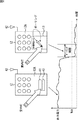
図2は、リモートコントローラ12の機能的構成を示すブロック図である。リモートコントローラ12は、アンテナ41、アンテナ42、太陽光発電パネル43、CPU(Central Processing Unit)51、非接触カードR/W部52、キー入力部53、メモリ54、無線通信制御部55、出力電力測定部56、および、蓄電池57を含むように構成される。
FIG. 2 is a block diagram showing a functional configuration of the
CPU51は、所定の制御プログラムを実行することにより、リモートコントローラ12の各部の制御を行う。
The
非接触カードR/W部52は、CPU51の制御の基に、アンテナ41を介して非接触カード13と通信を行い、非接触カード13の情報の読み書きを行う。また、非接触カードR/W部52は、非接触カード13から取得した情報をCPU51に供給する。
The non-contact card R /
なお、非接触カード13と非接触カードR/W部52との間の近接通信には、例えば、ISO(International Organization for Standardization)1443により規定された通信規格が適用され、13.56MHz帯の周波数の搬送波を用いて、最大424kビット/秒の通信が行われる。
Note that, for example, a communication standard defined by ISO (International Organization for Standardization) 1443 is applied to the proximity communication between the
キー入力部53は、TV11を遠隔操作するための各種のキー等により構成される。キー入力部53は、ユーザによってキーが押下されると、押下されたキーに応じたLowとHighの2つの状態の組み合わせによる信号を、CPU51との間の信号線に出力し、CPU51に割込み処理の実行を指令する。
The
割込み処理の指令を受けたCPU51は、メモリ54内に保持されたコマンドテーブルから、キー入力部53からの信号の状態に該当するコマンドコードを検索し取得する。CPU51は、取得したコマンドコードを、通信データのペイロードとして後段の無線通信制御部55に供給する。
The
無線通信制御部55は、無線通信制御部55が準拠する通信規格に規定されているフォーマットのパケットに、取得したペイロードを成形することにより、ベースバンド信号を生成する。無線通信制御部55は、生成したベースバンド信号を、所定の方式により変調し、所定の周波数(例えば、2.4GHz)にアップコンバートしてから、アンテナ42を介して送出する。TV11は、リモートコントローラ12から送出されたベースバンド信号を受信し、ベースバンド信号に示されるコマンドコードに対応したコマンド処理を行う。
The wireless
また、無線通信制御部55は、TV11から送信されてくるRF(Radio Frequency)信号をアンテナ42を介して受信し、RF信号のダウンコンバートおよび復調処理を行い、RF信号に含まれているパケットを取得する。無線通信制御部55は、取得したパケットからペイロードを抽出し、CPU51に供給する。CPU51は、取得したペイロードの解析を行い、その結果得られた情報に従って、リモートコントローラ12の各部の制御を行う。
Further, the radio
なお、TV11と無線通信制御部55との間の通信には、例えば、Bluetooth(登録商標)、ZigBee(商標)、IEEE(Institute of Electrical and Electronic Engineers)802.11(802.11a,802.11b,802.11gなど)により規定される無線LAN(Local Area Network)等の、低消費電力で双方向の無線通信が可能な方式が適用される。
For communication between the TV 11 and the wireless
太陽光発電パネル43は、太陽光や照明光などの入射光による光エネルギーを電力に変換し、変換した電力により蓄電池57の充電を行う。リモートコントローラ12は、この蓄電池57からの電力により駆動される。
The photovoltaic
出力電力測定部56は、太陽光発電パネル43により生成され、出力される電力の測定を行い、測定結果を示す情報をCPU51に供給する。
The output
次に、図3のフローチャートを参照して、リモートコントローラ12により実行される近接通信制御処理について説明する。
Next, the near field communication control process executed by the
ステップS1において、出力電力測定部56は、パネル電力、すなわち、太陽光発電パネル43の出力電力が、所定の閾値Wshを下回っているか否かを判定する。ステップS1の判定処理は、パネル電力が閾値Wshを下回っていると判定されるまで定期的に繰り返され、パネル電力が閾値Wshを下回っていると判定された場合、処理はステップS2に進む。
In step S1, the output
通常、リモートコントローラ12は、操作面12Aを上に向けて室内で操作するのが一般的である。そのような状態において、図4の左上に模式的に示されるように、室内灯からの光や太陽光などが太陽光発電パネル43に入射し、太陽光発電パネル43の発電、および、蓄電池57の充電が行われる。
Usually, the
一方、図4の右上に模式的に示されるように、ユーザが、アンテナ41に非接触カード13を翳した場合、アンテナ41の近傍に設置されている太陽光発電パネル43も、非接触カード13により覆われる。これにより、太陽光発電パネル43への入射光が、非接触カード13により遮断され、太陽光発電パネル43への入射光量が低下し、パネル電力が低下する。
On the other hand, as schematically shown in the upper right of FIG. 4, when the user puts the
そして、図4の左上の状態においてパネル電力が閾値Wshを超え、図4の右上の状態においてパネル電力が閾値Wshを下回るように、閾値Wshを適切に設定することにより、非接触カード13をアンテナ41に翳したとき、パネル電力が閾値Wshを下回り、処理がステップS2に進むようになる。 Then, by appropriately setting the threshold Wsh so that the panel power exceeds the threshold Wsh in the upper left state of FIG. 4 and the panel power is lower than the threshold Wsh in the upper right state of FIG. When the user goes to 41, the panel power falls below the threshold value Wsh, and the process proceeds to step S2.
ステップS2において、非接触カードR/W部52は、ポーリング処理を開始する。具体的には、出力電力測定部56は、パネル電力が閾値Wshを下回ったことをCPU51に通知する。CPU51は、例えば、図示せぬスイッチなどを制御して、蓄電池57から非接触カードR/W部52への電力の供給を開始させる。これにより、非接触カードR/W部52が起動する。さらに、CPU51は、非接触カードR/W部52にポーリング処理を実行するよう指令し、非接触カードR/W部52は、ポーリング処理を開始する。これにより、ポーリング信号が周期的にアンテナ41から発信され、非接触カードR/W部52の通信圏内における非接触カード13の探索が開始される。
In step S2, the non-contact card R /
非接触カード13は、リモートコントローラ12からポーリング信号を受信した場合、ポーリング信号に対する応答信号を送信する。
When the
ステップS3において、非接触カードR/W部52は、非接触カード13を捕捉したか否かを判定する。非接触カードR/W部52は、非接触カード13からの応答信号を受信していない場合、非接触カードを捕捉していないと判定し、処理はステップS4に進む。
In step S <b> 3, the non-contact card R /
ステップS4において、CPU51は、タイムアウトが発生したか否かを判定する。CPU51は、非接触カードR/W部52を起動してからまだ所定の時間が経過していない場合、タイムアウトは発生していないと判定し、処理はステップS3に戻る。
In step S4, the
その後、ステップS3において、非接触カード13を捕捉したと判定されるか、ステップS4において、タイムアウトが発生したと判定されるまで、ステップS3およびS4の判定処理が繰り返し実行される。
Thereafter, the determination process of steps S3 and S4 is repeatedly executed until it is determined in step S3 that the
一方、ステップS3において、非接触カードR/W部52は、非接触カード13からの応答信号をアンテナ41を介して受信した場合、非接触カードを捕捉したと判定し、処理はステップS5に進む。
On the other hand, when the response signal from the
ステップS5において、非接触カードR/W部52は、非接触カード13と通信を行う。例えば、非接触カードR/W部52は、CPU51の制御の基に、アンテナ41を介して非接触カード13と通信を行い、上述したオンラインショッピングの決済に必要な情報の読み書きを行う。その後、非接触カードR/W部52と非接触カード13との通信が終了すると、処理はステップS6に進む。
In step S <b> 5, the contactless card R /
一方、ステップS4において、CPU51は、非接触カードR/W部52を起動してから、非接触カード13からの応答信号を受信しないまま所定の時間が経過した場合、換言すれば、非接触カード13との通信が行われないまま所定の時間が経過した場合、タイムアウトが発生したと判定し、処理はステップS6に進む。
On the other hand, in step S4, the
ステップS6において、CPU51は、非接触カードR/W部52の動作を停止させる。具体的には、CPU51は、例えば、図示せぬスイッチを制御して、蓄電池57から非接触カードR/W部52への電力の供給を停止させ、非接触カードR/W部52の動作を停止させる。このように、非接触カード13との通信終了後に加えて、タイムアウトが発生したときに非接触カードR/W部52の動作を停止させることにより、非接触カード13をアンテナ41に翳す以外の要因、例えば、部屋を暗くしたり、リモートコントローラ12の操作面12Aを下に向けるなどの要因により、パネル電力が閾値Wshを下回り、そのままポーリング処理が継続されてしまい、無駄な電力が消費されることが防止される。
In step S <b> 6, the
ステップS7において、出力電力測定部56は、パネル電力が閾値Wshを上回っているか否かを判定する。ステップS7の判定処理は、パネル電力が閾値Wshを上回っていると判定されるまで定期的に繰り返される。これにより、例えば、部屋を暗くしたり、リモートコントローラ12の操作面12Aを下に向けるなどの要因により、太陽光発電パネル43への入射光量が小さい状態が継続した場合に、ポーリング処理が再開されてしまい、無駄な電力が消費されることが防止される。
In step S7, the output
一方、ステップS7において、パネル電力が閾値Wshを上回っていると判定された場合、処理はステップS1に戻り、上述したステップS1以降の処理が実行される。 On the other hand, when it is determined in step S7 that the panel power exceeds the threshold value Wsh, the process returns to step S1, and the processes after step S1 described above are executed.
このようして、非接触カードR/W部52がポーリング処理を行う期間を限定し、リモートコントローラ12の消費電力を低減することができる。また、ポーリング処理を行う期間を限定しても、非接触カードR/W部52と非接触カード13との間の通信を確実に行うことができる。
Thus, the period during which the non-contact card R /
また、太陽光発電パネル43により蓄電池57を充電することにより、蓄電池57を交換する間隔を長くすることができる。
Further, by charging the
なお、図3の近接通信制御処理では、例えば、ユーザが暗い部屋でTV11を見ていて、パネル電力が閾値Wshを上回らない場合、一度ポーリング処理を行った後、ポーリング処理が再開されなくなり、リモートコントローラ12と非接触カード13との近接通信が行えなくなることが想定される。
In the proximity communication control process of FIG. 3, for example, when the user is watching the TV 11 in a dark room and the panel power does not exceed the threshold value Wsh, the polling process is not resumed after the polling process is performed once. It is assumed that proximity communication between the
そこで、図5のフローチャートを参照して、暗い部屋でもリモートコントローラ12と非接触カード13との近接通信を確実に行えるようにする方法の一例について説明する。
Therefore, an example of a method for ensuring the proximity communication between the
ステップS31において、図3のステップS1の処理と同様に、パネル電力が閾値Wshを下回っているか否かが判定される。パネル電力が閾値Wshを下回っていないと判定された場合、処理はステップS32に進む。 In step S31, it is determined whether or not the panel power is below the threshold value Wsh, as in the process of step S1 of FIG. If it is determined that the panel power is not lower than the threshold value Wsh, the process proceeds to step S32.
ステップS32において、無線通信制御部55は、リーダライタ起動信号を受信したか否かを判定する。リーダライタ起動信号を受信していないと判定された場合、処理はステップS31に戻り、ステップS31において、パネル電力が閾値Wshを下回っていると判定されるか、ステップS32において、リーダライタ起動信号を受信したと判定されるまで、ステップS31およびS32の処理が繰り返し実行される。
In step S32, the wireless
例えば、ユーザが、TV11を見ながらオンラインショッピングを利用している場合に、リモートコントローラ12を操作して、商品の購入を確定し、決済処理に遷移する指令を入力した場合について考える。例えば、TV11は、オンラインショッピングの画面の表示中に、ユーザが商品の購入を確定し、決済処理に遷移する指令を入力したことを検知した場合、アンテナ31を介して、リーダライタ起動信号を送信する。
For example, let us consider a case where the user uses online shopping while watching the TV 11, operates the
無線通信制御部55は、アンテナ42を介して、そのリーダライタ起動信号を受信した場合、ステップS32において、リーダライタ起動信号を受信したと判定し、処理はステップS33に進む。
When receiving the reader / writer activation signal via the
一方、ステップS31において、パネル電力が閾値Wshを下回っていると判定された場合も、処理はステップS33に進む。 On the other hand, when it is determined in step S31 that the panel power is lower than the threshold value Wsh, the process proceeds to step S33.
ステップS33乃至S37の処理は、図3のステップS2乃至S6の処理と同様である。すなわち、非接触カードR/W部52のポーリング処理が開始され、非接触カードR/W部52が非接触カード13を捕捉した場合、非接触カードR/W部52と非接触カード13との通信が行われ、通信終了後、非接触カードR/W部52の動作が停止される。一方、非接触カードR/W部52が非接触カード13を捕捉できずにタイムアウトが発生した場合、非接触カードR/W部52の動作が停止され、ポーリング処理が終了する。
The processing in steps S33 to S37 is the same as the processing in steps S2 to S6 in FIG. That is, when the polling process of the non-contact card R /
ステップS38において、図3のステップS7の処理と同様に、パネル電力が閾値Wshを上回っているか否かが判定され、パネル電力が閾値Wshを上回っていないと判定された場合、処理はステップS39に進む。 In step S38, as in the process of step S7 of FIG. 3, it is determined whether or not the panel power exceeds the threshold value Wsh. If it is determined that the panel power does not exceed the threshold value Wsh, the process proceeds to step S39. move on.
ステップS39において、ステップS32の処理と同様に、リーダライタ起動信号を受信したか否かが判定され、リーダライタ起動信号を受信していないと判定された場合、処理はステップS38に戻る。その後、ステップS38において、パネル電力が閾値Wshを上回っていると判定されるか、ステップS39において、リーダライタ起動信号を受信したと判定されるまで、ステップS38およびS39の判定処理が繰り返し実行される。 In step S39, similarly to the process of step S32, it is determined whether or not a reader / writer activation signal has been received. If it is determined that a reader / writer activation signal has not been received, the process returns to step S38. Thereafter, the determination process of steps S38 and S39 is repeatedly executed until it is determined in step S38 that the panel power exceeds the threshold value Wsh or until it is determined in step S39 that the reader / writer activation signal has been received. .
一方、ステップS39において、リーダライタ起動信号を受信したと判定された場合、処理はステップS33に戻り、上述したステップS33以降の処理が実行される。これにより、例えば、部屋が暗くてパネル電力が閾値Wshを上回らない状態においても、リモートコントローラ12と非接触カード13との近接通信を行うことが可能になる。
On the other hand, if it is determined in step S39 that the reader / writer activation signal has been received, the process returns to step S33, and the processes after step S33 described above are executed. Thereby, for example, even when the room is dark and the panel power does not exceed the threshold value Wsh, it is possible to perform near field communication between the
一方、ステップS38において、パネル電力が閾値Wshを上回っていると判定された場合、処理はステップS31に戻り、ステップS31以降の処理が実行される。 On the other hand, when it is determined in step S38 that the panel power exceeds the threshold value Wsh, the process returns to step S31, and the processes after step S31 are executed.
このようにして、例えば、暗い部屋でTV11を見ながらオンラインショッピングを利用している場合にも、リモートコントローラ12と非接触カード13との間の近接通信を確実に行い、オンラインショッピングの決済を行うことができる。
In this way, for example, even when using online shopping while watching the TV 11 in a dark room, the proximity communication between the
なお、TV11からリーダライタ起動信号を送信するタイミングは、上述した例に限定されるものではなく、必要に応じて任意のタイミングに設定することが可能である。 Note that the timing at which the reader / writer activation signal is transmitted from the TV 11 is not limited to the above-described example, and can be set to any timing as necessary.
さらに、例えば、リーダライタ起動信号を送信してからタイムアウトが発生するまでの間、リモートコントローラ12と非接触カード13との間の通信が可能であることを、TV11の画面に表示するようにしてもよい。
Further, for example, a message indicating that communication between the
なお、本発明は、上述した例以外の他のアプリケーションに適用することが可能である。例えば、非接触カードR/W部52が非接触カード13を捕捉したことをトリガーにして、リモートコントローラ12が、非接触カード13のフリーアクセス領域に格納されている情報を読み出し、TV11に送信するようなアプリケーションが考えられる。この場合、非接触カード13のフリーアクセス領域から読み出す情報としては、例えば、交通機関の利用履歴や買い物の履歴などが考えられる。
It should be noted that the present invention can be applied to other applications other than the examples described above. For example, the
また、例えば、リモートコントローラ12が、非接触カード13のフリーアクセス領域に格納されているURLの情報を読み出し、読み出したURLの情報をTV11に送信し、そのURLに存在するWebサイトへの接続をTV11に指示するようなアプリケーションが考えられる。
Further, for example, the
また、以上の説明では、リモートコントローラ12への入射光量の検出に太陽光発電パネルを用いる例を示したが、例えば、発電機能を有しない受光センサなどを用いて、入射光量を検出するようにしてもよい。
In the above description, an example in which a photovoltaic power generation panel is used to detect the amount of incident light to the
さらに、以上の説明では、情報処理システム1において、TV、リモートコントローラ、非接触カード、および、決済サーバを1つずつ設ける例を示したが、それぞれ2つ以上設けるようにすることも可能である。
Furthermore, in the above description, in the
なお、以上の説明では、本発明をTVのリモートコントローラに適用する例を示したが、本発明は、非接触カードと近接通信を行う他の通信装置、例えば、カードリーダライタ、携帯電話機、パーソナルコンピュータ、PDA(Personal Digital Assistant)等にも適用することができる。 In the above description, the example in which the present invention is applied to a TV remote controller has been shown. However, the present invention can be applied to other communication devices that perform proximity communication with a contactless card, such as a card reader / writer, a cellular phone, a personal phone, and the like. It can also be applied to computers, PDAs (Personal Digital Assistants) and the like.
また、以上の説明では、本発明を適用した通信装置と近接通信を行う相手を非接触カードとする例を示したが、非接触カード機能を有する装置(例えば、携帯電話機など)とすることも可能である。 Further, in the above description, an example in which a communication device to which the present invention is applied and a partner that performs proximity communication is a contactless card is shown, but a device having a contactless card function (for example, a mobile phone) may be used. Is possible.
上述した一連の処理は、ハードウエアにより実行することもできるし、ソフトウエアにより実行することもできる。一連の処理をソフトウエアにより実行する場合には、そのソフトウエアを構成するプログラムが、専用のハードウエアに組み込まれているコンピュータ、または、各種のプログラムをインストールすることで、各種の機能を実行することが可能な、例えば汎用のパーソナルコンピュータなどに、プログラム記録媒体からインストールされる。 The series of processes described above can be executed by hardware or can be executed by software. When a series of processing is executed by software, a program constituting the software executes various functions by installing a computer incorporated in dedicated hardware or various programs. For example, it is installed from a program recording medium in a general-purpose personal computer or the like.
なお、コンピュータが実行するプログラムは、本明細書で説明する順序に沿って時系列に処理が行われるプログラムであっても良いし、並列に、あるいは呼び出しが行われたとき等の必要なタイミングで処理が行われるプログラムであっても良い。 The program executed by the computer may be a program that is processed in time series in the order described in this specification, or in parallel or at a necessary timing such as when a call is made. It may be a program for processing.
また、本明細書において、システムの用語は、複数の装置、手段などより構成される全体的な装置を意味するものとする。 Further, in the present specification, the term “system” means an overall apparatus composed of a plurality of apparatuses and means.
さらに、本発明の実施の形態は、上述した実施の形態に限定されるものではなく、本発明の要旨を逸脱しない範囲において種々の変更が可能である。 Furthermore, the embodiments of the present invention are not limited to the above-described embodiments, and various modifications can be made without departing from the gist of the present invention.
1 情報処理システム, 11 TV, 12 リモートコントローラ, 13 非接触カード, 14 決済サーバ, 21 インターネット, 41 アンテナ, 42 アンテナ, 43 太陽光発電パネル, 51 CPU, 52 非接触カードリーダライタ部, 53 キー入力部, 55 無線通信制御部, 56 出力電力測定部, 57 蓄電池 1 Information processing system, 11 TV, 12 Remote controller, 13 Contactless card, 14 Payment server, 21 Internet, 41 Antenna, 42 Antenna, 43 Photovoltaic panel, 51 CPU, 52 Contactless card reader / writer, 53 Key input Unit, 55 wireless communication control unit, 56 output power measurement unit, 57 storage battery
Claims (5)
前記アンテナを介して非接触カードと近接通信を行う第1の通信手段と、
前記アンテナの近傍に設けられ、入射光量を検出する光検出手段と、
前記入射光量が所定の閾値未満になった場合、前記第1の通信手段を起動する近接通信制御手段と
を含み、
電池により駆動される通信装置。 An antenna,
First communication means for performing proximity communication with a contactless card via the antenna;
A light detecting means provided in the vicinity of the antenna for detecting the amount of incident light;
A proximity communication control means for activating the first communication means when the incident light quantity is less than a predetermined threshold;
A communication device driven by a battery.
請求項1に記載の通信装置。 The proximity communication control means stops the operation of the first communication means when a predetermined time has passed without starting the proximity communication with the contactless card after starting the first communication means. The communication apparatus according to claim 1, wherein the first communication unit is not activated until the amount of incident light exceeds the threshold value.
さらに含む請求項1または2に記載の通信装置。 The communication apparatus according to claim 1, further comprising second communication means for transmitting information acquired from the contactless card to another apparatus.
請求項3に記載の通信装置。 The communication device according to claim 3, wherein the proximity communication control unit activates the first communication unit when receiving a predetermined activation signal from the other device via the second communication unit.
請求項1に記載の通信装置。 The communication device according to claim 1, wherein the light detection unit includes a photovoltaic panel that converts incident light into electric power and charges the battery.
Priority Applications (5)
| Application Number | Priority Date | Filing Date | Title |
|---|---|---|---|
| JP2008178881A JP4552158B2 (en) | 2008-07-09 | 2008-07-09 | Communication device |
| US12/496,279 US8232882B2 (en) | 2008-07-09 | 2009-07-01 | Photodetector used to control near field communication |
| EP09164885A EP2144186B1 (en) | 2008-07-09 | 2009-07-08 | Communication apparatus |
| CN200910158933A CN101626257A (en) | 2008-07-09 | 2009-07-08 | Communication apparatus |
| AT09164885T ATE545916T1 (en) | 2008-07-09 | 2009-07-08 | COMMUNICATION DEVICE |
Applications Claiming Priority (1)
| Application Number | Priority Date | Filing Date | Title |
|---|---|---|---|
| JP2008178881A JP4552158B2 (en) | 2008-07-09 | 2008-07-09 | Communication device |
Related Child Applications (1)
| Application Number | Title | Priority Date | Filing Date |
|---|---|---|---|
| JP2010162895A Division JP5267518B2 (en) | 2010-07-20 | 2010-07-20 | Communication device |
Publications (2)
| Publication Number | Publication Date |
|---|---|
| JP2010020453A true JP2010020453A (en) | 2010-01-28 |
| JP4552158B2 JP4552158B2 (en) | 2010-09-29 |
Family
ID=41211988
Family Applications (1)
| Application Number | Title | Priority Date | Filing Date |
|---|---|---|---|
| JP2008178881A Expired - Fee Related JP4552158B2 (en) | 2008-07-09 | 2008-07-09 | Communication device |
Country Status (5)
| Country | Link |
|---|---|
| US (1) | US8232882B2 (en) |
| EP (1) | EP2144186B1 (en) |
| JP (1) | JP4552158B2 (en) |
| CN (1) | CN101626257A (en) |
| AT (1) | ATE545916T1 (en) |
Cited By (4)
| Publication number | Priority date | Publication date | Assignee | Title |
|---|---|---|---|---|
| JP2010206317A (en) * | 2009-02-27 | 2010-09-16 | Sony Corp | Wireless communication device, information processing device, wireless communication method, and information processing system |
| US8068011B1 (en) | 2010-08-27 | 2011-11-29 | Q Street, LLC | System and method for interactive user-directed interfacing between handheld devices and RFID media |
| JP2013246498A (en) * | 2012-05-23 | 2013-12-09 | Nec Access Technica Ltd | Electronic apparatus and control method of electronic apparatus |
| WO2014097755A1 (en) * | 2012-12-20 | 2014-06-26 | ソニー株式会社 | Communication device, communication method, communication system, and computer program |
Families Citing this family (7)
| Publication number | Priority date | Publication date | Assignee | Title |
|---|---|---|---|---|
| US9466877B2 (en) | 2011-11-29 | 2016-10-11 | Hill-Rom Services, Inc. | Hospital bed having near field communication capability |
| WO2013133764A1 (en) * | 2012-03-09 | 2013-09-12 | Mediatek Singapore Pte. Ltd. | Mobile device and remote control connection for electronic device via near field communication |
| JP6457210B2 (en) * | 2014-07-10 | 2019-01-23 | Juki株式会社 | Sewing machine operation panel and sewing machine |
| CN104463270A (en) * | 2014-11-12 | 2015-03-25 | 惠州Tcl移动通信有限公司 | Intelligent terminal, financial card and financial management system based on RFID |
| CN105592032B (en) * | 2014-12-23 | 2018-11-27 | 中国银联股份有限公司 | Safety information interaction method Internet-based |
| JP6292288B1 (en) * | 2016-12-09 | 2018-03-14 | ダイキン工業株式会社 | Remote controller |
| US11402814B2 (en) * | 2020-04-22 | 2022-08-02 | Capital One Services, Llc | Interactive home system including wireless devices |
Citations (2)
| Publication number | Priority date | Publication date | Assignee | Title |
|---|---|---|---|---|
| JPH0514978A (en) * | 1991-07-05 | 1993-01-22 | Pioneer Electron Corp | Remote controller |
| JP2002334305A (en) * | 2001-05-09 | 2002-11-22 | Tamura Electric Works Ltd | Non-contact ic card reader writer |
Family Cites Families (6)
| Publication number | Priority date | Publication date | Assignee | Title |
|---|---|---|---|---|
| FR1531508A (en) | 1967-05-19 | 1968-07-05 | Automatic sorting system for items such as mail bags | |
| JP4342592B2 (en) | 1998-04-15 | 2009-10-14 | 三菱レイヨン株式会社 | Method for producing hollow fiber membrane element and hollow fiber membrane module |
| US6150948A (en) | 1999-04-24 | 2000-11-21 | Soundcraft, Inc. | Low-power radio frequency identification reader |
| EP3154206A1 (en) | 2004-10-29 | 2017-04-12 | Sony Deutschland Gmbh | Method for operating a near field communication system |
| US20080117055A1 (en) * | 2006-11-20 | 2008-05-22 | Metrologic Instruments, Inc. | Light activated radio frequency identification conveyance system |
| JP4872625B2 (en) | 2006-11-24 | 2012-02-08 | コニカミノルタビジネステクノロジーズ株式会社 | Image forming apparatus |
-
2008
- 2008-07-09 JP JP2008178881A patent/JP4552158B2/en not_active Expired - Fee Related
-
2009
- 2009-07-01 US US12/496,279 patent/US8232882B2/en not_active Expired - Fee Related
- 2009-07-08 EP EP09164885A patent/EP2144186B1/en not_active Not-in-force
- 2009-07-08 AT AT09164885T patent/ATE545916T1/en active
- 2009-07-08 CN CN200910158933A patent/CN101626257A/en active Pending
Patent Citations (2)
| Publication number | Priority date | Publication date | Assignee | Title |
|---|---|---|---|---|
| JPH0514978A (en) * | 1991-07-05 | 1993-01-22 | Pioneer Electron Corp | Remote controller |
| JP2002334305A (en) * | 2001-05-09 | 2002-11-22 | Tamura Electric Works Ltd | Non-contact ic card reader writer |
Cited By (7)
| Publication number | Priority date | Publication date | Assignee | Title |
|---|---|---|---|---|
| JP2010206317A (en) * | 2009-02-27 | 2010-09-16 | Sony Corp | Wireless communication device, information processing device, wireless communication method, and information processing system |
| US8068011B1 (en) | 2010-08-27 | 2011-11-29 | Q Street, LLC | System and method for interactive user-directed interfacing between handheld devices and RFID media |
| US8395486B2 (en) | 2010-08-27 | 2013-03-12 | Q Street, LLC | System and method for interactive user-directed interfacing between handheld devices and RFID media |
| US9858455B2 (en) | 2010-08-27 | 2018-01-02 | Q Street, LLC | System and method for interactive user-directed interfacing between handheld devices and RFID media |
| JP2013246498A (en) * | 2012-05-23 | 2013-12-09 | Nec Access Technica Ltd | Electronic apparatus and control method of electronic apparatus |
| WO2014097755A1 (en) * | 2012-12-20 | 2014-06-26 | ソニー株式会社 | Communication device, communication method, communication system, and computer program |
| JPWO2014097755A1 (en) * | 2012-12-20 | 2017-01-12 | サターン ライセンシング エルエルシーSaturn Licensing LLC | COMMUNICATION DEVICE AND COMMUNICATION METHOD, COMMUNICATION SYSTEM, AND COMPUTER PROGRAM |
Also Published As
| Publication number | Publication date |
|---|---|
| ATE545916T1 (en) | 2012-03-15 |
| EP2144186A3 (en) | 2010-11-10 |
| US8232882B2 (en) | 2012-07-31 |
| EP2144186A2 (en) | 2010-01-13 |
| EP2144186B1 (en) | 2012-02-15 |
| CN101626257A (en) | 2010-01-13 |
| US20100007504A1 (en) | 2010-01-14 |
| JP4552158B2 (en) | 2010-09-29 |
Similar Documents
| Publication | Publication Date | Title |
|---|---|---|
| JP4552158B2 (en) | Communication device | |
| CN101827434B (en) | Radio communication apparatus, radio communication method and program | |
| KR102005460B1 (en) | Method and apparatus for energy harvest from a proximity coupling device | |
| JP5637641B2 (en) | Wireless power charging method and apparatus | |
| EP2084821B1 (en) | Near field communication (nfc) activation | |
| EP2541995B1 (en) | Method and apparatus for reducing power consumption of a NFC powered device | |
| US8446257B2 (en) | Radio frequency charging system | |
| JP2013187783A (en) | Communication system and portable machine | |
| CN102044028A (en) | Mobile payment realizing method and mobile payment system | |
| JP5267518B2 (en) | Communication device | |
| JP2007067818A (en) | Communication terminal device, communication system and communication method | |
| US20180349655A1 (en) | Wireless communication apparatus, host terminal, and wireless communication system | |
| JP2013185343A (en) | Electronic key with charging function | |
| JP2010067035A (en) | Device for wireless communication | |
| JP5143464B2 (en) | DATA READING DEVICE, DATA READING SYSTEM, AND DATA READING METHOD | |
| KR101296197B1 (en) | Key input device by near field communication and operating method thereof | |
| US9350849B2 (en) | Communication apparatus, processing method and computer-readable recording medium | |
| KR101455695B1 (en) | Method of System Wake-Up for Wireless Power Transfer Apparatus | |
| JP5718127B2 (en) | COMMUNICATION DEVICE, COMMUNICATION METHOD, AND PROGRAM | |
| KR20230090078A (en) | Wireless tag apparatus | |
| JP2014179752A (en) | RFID system | |
| KR101592362B1 (en) | Uhf rfid tag, devices including same, and method thereof | |
| JP5062154B2 (en) | Portable terminal device and reader / writer device | |
| JP2005094586A (en) | Radio communication apparatus, radio communications method, and radio communication medium | |
| KR20060001134A (en) | Rf id reader with wireless communication function between rf id readers |
Legal Events
| Date | Code | Title | Description |
|---|---|---|---|
| A977 | Report on retrieval |
Free format text: JAPANESE INTERMEDIATE CODE: A971007 Effective date: 20100407 |
|
| A131 | Notification of reasons for refusal |
Free format text: JAPANESE INTERMEDIATE CODE: A131 Effective date: 20100413 |
|
| A521 | Request for written amendment filed |
Free format text: JAPANESE INTERMEDIATE CODE: A523 Effective date: 20100531 |
|
| TRDD | Decision of grant or rejection written | ||
| A01 | Written decision to grant a patent or to grant a registration (utility model) |
Free format text: JAPANESE INTERMEDIATE CODE: A01 Effective date: 20100617 |
|
| A01 | Written decision to grant a patent or to grant a registration (utility model) |
Free format text: JAPANESE INTERMEDIATE CODE: A01 |
|
| A61 | First payment of annual fees (during grant procedure) |
Free format text: JAPANESE INTERMEDIATE CODE: A61 Effective date: 20100630 |
|
| FPAY | Renewal fee payment (event date is renewal date of database) |
Free format text: PAYMENT UNTIL: 20130723 Year of fee payment: 3 |
|
| FPAY | Renewal fee payment (event date is renewal date of database) |
Free format text: PAYMENT UNTIL: 20130723 Year of fee payment: 3 |
|
| R250 | Receipt of annual fees |
Free format text: JAPANESE INTERMEDIATE CODE: R250 |
|
| R250 | Receipt of annual fees |
Free format text: JAPANESE INTERMEDIATE CODE: R250 |
|
| LAPS | Cancellation because of no payment of annual fees |