EP2144186A2 - Communication apparatus - Google Patents
Communication apparatus Download PDFInfo
- Publication number
- EP2144186A2 EP2144186A2 EP09164885A EP09164885A EP2144186A2 EP 2144186 A2 EP2144186 A2 EP 2144186A2 EP 09164885 A EP09164885 A EP 09164885A EP 09164885 A EP09164885 A EP 09164885A EP 2144186 A2 EP2144186 A2 EP 2144186A2
- Authority
- EP
- European Patent Office
- Prior art keywords
- communication
- contact card
- antenna
- near field
- incoming light
- Prior art date
- Legal status (The legal status is an assumption and is not a legal conclusion. Google has not performed a legal analysis and makes no representation as to the accuracy of the status listed.)
- Granted
Links
Images


Classifications
-
- G—PHYSICS
- G06—COMPUTING; CALCULATING OR COUNTING
- G06K—GRAPHICAL DATA READING; PRESENTATION OF DATA; RECORD CARRIERS; HANDLING RECORD CARRIERS
- G06K7/00—Methods or arrangements for sensing record carriers, e.g. for reading patterns
- G06K7/0008—General problems related to the reading of electronic memory record carriers, independent of its reading method, e.g. power transfer
-
- G—PHYSICS
- G06—COMPUTING; CALCULATING OR COUNTING
- G06K—GRAPHICAL DATA READING; PRESENTATION OF DATA; RECORD CARRIERS; HANDLING RECORD CARRIERS
- G06K7/00—Methods or arrangements for sensing record carriers, e.g. for reading patterns
- G06K7/10—Methods or arrangements for sensing record carriers, e.g. for reading patterns by electromagnetic radiation, e.g. optical sensing; by corpuscular radiation
- G06K7/10009—Methods or arrangements for sensing record carriers, e.g. for reading patterns by electromagnetic radiation, e.g. optical sensing; by corpuscular radiation sensing by radiation using wavelengths larger than 0.1 mm, e.g. radio-waves or microwaves
- G06K7/10118—Methods or arrangements for sensing record carriers, e.g. for reading patterns by electromagnetic radiation, e.g. optical sensing; by corpuscular radiation sensing by radiation using wavelengths larger than 0.1 mm, e.g. radio-waves or microwaves the sensing being preceded by at least one preliminary step
- G06K7/10128—Methods or arrangements for sensing record carriers, e.g. for reading patterns by electromagnetic radiation, e.g. optical sensing; by corpuscular radiation sensing by radiation using wavelengths larger than 0.1 mm, e.g. radio-waves or microwaves the sensing being preceded by at least one preliminary step the step consisting of detection of the presence of one or more record carriers in the vicinity of the interrogation device
-
- G—PHYSICS
- G06—COMPUTING; CALCULATING OR COUNTING
- G06K—GRAPHICAL DATA READING; PRESENTATION OF DATA; RECORD CARRIERS; HANDLING RECORD CARRIERS
- G06K7/00—Methods or arrangements for sensing record carriers, e.g. for reading patterns
- G06K7/10—Methods or arrangements for sensing record carriers, e.g. for reading patterns by electromagnetic radiation, e.g. optical sensing; by corpuscular radiation
- G06K7/10009—Methods or arrangements for sensing record carriers, e.g. for reading patterns by electromagnetic radiation, e.g. optical sensing; by corpuscular radiation sensing by radiation using wavelengths larger than 0.1 mm, e.g. radio-waves or microwaves
- G06K7/10198—Methods or arrangements for sensing record carriers, e.g. for reading patterns by electromagnetic radiation, e.g. optical sensing; by corpuscular radiation sensing by radiation using wavelengths larger than 0.1 mm, e.g. radio-waves or microwaves setting parameters for the interrogator, e.g. programming parameters and operating modes
- G06K7/10207—Methods or arrangements for sensing record carriers, e.g. for reading patterns by electromagnetic radiation, e.g. optical sensing; by corpuscular radiation sensing by radiation using wavelengths larger than 0.1 mm, e.g. radio-waves or microwaves setting parameters for the interrogator, e.g. programming parameters and operating modes parameter settings related to power consumption of the interrogator
Definitions
- the present invention relates to a communication apparatus, and, more particularly, to a communication apparatus which performs near field communication with a non-contact card.
- TV television receiver
- a card reader/writer (hereinafter called card R/W) which reads information from a non-contact card may be mounted in a remote controller for the TV. Then, the user needs to merely place a credit card made by a non-contact card over the remote controller to easily carry out a procedure for settlement for on-line shopping without performing an operation of entering a password, a card number and so forth.
- One solution to the problem proposed is to periodically shift the mode of the near field radio communication apparatus among three modes, an idling mode, a target operation mode and an initiator operation mode, and to permit the polling process to be performed only in the initiator operation mode (see Patent Document 1 ( JP-A-2006-129498 ).
- Adapting the invention described in the Patent Document 1 to the above-described TV remote controller makes it possible to shorten the time for the polling process, reduce power consumption and prolong the battery life.
- the life of the battery of the remote controller merely becomes about ten times longer to be 210 hours under the foregoing conditions. This is not sufficient for the life of the battery of the TV remote controller which is generally used at present is about one to two years.
- a communication apparatus including an antenna, a first communication means that performs near field communication with a non-contact card via the antenna, a photodetecting means that is provided near the antenna and detects an amount of incoming light, and a near field communication control means that activates the first communication means when the amount of incoming light becomes less than a predetermined threshold value, the communication apparatus being driven by a battery.
- the near field communication control means may be configured to stop operating the first communication means and not to activate the first communication means until the amount of incoming light exceeds the threshold value, when a predetermined time elapses without near field communication with the non-contact card after activating the first communication means.
- the communication apparatus may further include a second communication means that transmits information acquired from the non-contact card to another apparatus.
- the near field communication control means may be configured to activate the first communication means when receiving a predetermined activation signal from the another apparatus via the second communication means.
- the photodetecting means may include a photovoltaic power generating panel to convert incoming light to power to charge the battery therewith.
- the first communication means that performs near field communication with a non-contact card via the antenna is activated when the amount of incoming light becomes less than a predetermined threshold value.
- near field communication with a non-contact card can be controlled.
- power to be consumed in near field communication with a non-contact card can be reduced, resulting in prolongation of the battery life.
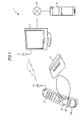
- FIG. 1 is a block diagram showing one embodiment of an information processing system 1 to which the present invention is adapted.
- the information processing system 1 in FIG. 1 is configured to include a TV 11, a remote controller 12, a non-contact card 13, and a settlement server 14.
- the information processing system 1 can use the TV 11 to utilize services using an Internet 21, such as on-line shopping.
- the TV 11 is connected to the Internet 21 to be able to communicate with another apparatus, such as the settlement server 14, over the Internet 21.
- the remote controller 12 carries out bidirectional radio communication with the TV 11 via an antenna 42 and an antenna 31 of the TV 11 to remotely operate the TV 11.
- the remote controller 12 incorporates a non-contact card reader/writer (R/W) section 52 (see FIG. 2 ) which reads or write information from or to the non-contact card 13.
- the remote controller 12 is provided with an antenna 41 in such a way that the receiving surface comes to an operation surface 12A having various operation keys provided thereon.
- the remote controller 12 and the non-contact card 13 perform electromagnetic-induction-based near field communication (NFC).
- NFC means communication which is enabled when the distance between communicating apparatuses comes within several tens of cm, and includes communication in which (casings of) communicating apparatuses are in contact with each other.
- a photovoltaic power generating panel 43 is provided near the antenna 41 on the operation surface 12A of the remote controller 12.
- the photovoltaic power generating panel 43 generates power based on the incoming light, such as sunlight or illumination light, to charge a battery for driving the remote controller 12.
- the non-contact card 13 is made by, for example, a non-contact type IC card which performs NFC.
- the settlement server 14 communicates with the TV 11 over the Internet 21 to perform a process of settlement for on-line shopping.
- a user operates, for example, the remote controller 12 to select a program of on-line shopping from digital broadcast waves received by the TV 11, or access a Web site provided by an on-line shopping service over the Internet 21 to display an on-line shopping screen on the TV 11. Then, the user operates the remote controller 12 according to information in the screen to determine a commodity to be purchased.
- the data portion in broadcast waves received by the TV 11 or commodity information acquired from a Web site includes information indicating the URL (Uniform Resource Locator) of the settlement server 14.
- the TV 11 connects to the settlement server 14 over the Internet 21 based on the URL information.
- the remote controller 12 When the user places the non-contact card 13 over the antenna 41 of the remote controller 12, the remote controller 12 initiates a polling process of periodically generating electromagnetic waves around to search for a communicatable non-contact card, as will be described in reference to FIG. 4 . Then, communication between the remote controller 12 and the non-contact card 13 is established, so that the non-contact card 13 and the settlement server 14 become communicatable with each other via the remote controller 12, the TV 11 and the Internet 21.
- the settlement server 14 performs an authentication process on the non-contact card 13 to verify that the non-contact card 13 is a reliable counterpart, then encrypts the transmission path to exchange information on a user ID, a payment amount, etc., which are needed for settlement, with the non-contact card 13. Further, the settlement server 14 performs a settlement process, such as updating balance history information in the memory of the non-contact card 13 and a database in the local server.
- the user can enjoy Internet shopping using the TV 11 in this manner.
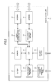
- FIG. 2 is a block diagram showing the functional configuration of the remote controller 12.
- the remote controller 12 is configured to have the antenna 41, the antenna 42, the photovoltaic power generating panel 43, a CPU (Central Processing Unit) 51, the non-contact card R/W section 52, a key input section 53, a memory 54, a radio communication control section 55, an output power measuring section 56, and a battery 57.
- CPU Central Processing Unit
- the CPU 51 executes a predetermined control program to control the individual sections of the remote controller 12.
- the non-contact card R/W section 52 communicates with the non-contact card 13 via the antenna 41 to read or write information from or to the non-contact card 13 under the control of the CPU 51.
- the non-contact card R/W section 52 supplies the CPU 51 with the information acquired from the non-contact card 13.
- NFC between the non-contact card 13 and the non-contact card R/W section 52 is carried out using the communication standard defined by, for example, ISO (International Organization for Standardization) 1443, and at a transmission rate of 424 Kbits/sec at a maximum using a carrier wave of the 13.56 MHz band.
- ISO International Organization for Standardization
- the key input section 53 includes various keys for remotely operate the TV 11. When the user presses a key, the key input section 53 sends a signal representing a combination of two states, Low and High, according to the pressed key to a signal line connected to the CPU 51 to instruct the CPU 51 to execute an interruption process.
- the CPU 51 Upon reception of the interruption instruction, the CPU 51 searches a command table held in the memory 54 to acquire a command code corresponding to the status of the signal from the key input section 53. The CPU 51 supplies the acquired command code to the radio communication control section 55 at the subsequent stage as a payload of communication data.
- the radio communication control section 55 forms the acquired payload into a packet of the format that is defined by the communication standard to which the radio communication control section 55 conforms, thus generating a base band signal.
- the radio communication control section 55 modulates the generated base band signal according to a predetermined system, up-converts the base band signal to have a predetermined frequency (e.g., 2.4 GHz), and then sends the resultant signal via the antenna 42.
- the TV 11 receives the base band signal transmitted from the remote controller 12, and performs a command process corresponding to the command code indicated by the base band signal.
- the radio communication control section 55 receives an RF (Radio Frequency) signal transmitted from the TV 11 via the antenna 42, and performs down-conversion and demodulation on the RF signal to acquire a packet included in the RF signal.
- the radio communication control section 55 extracts a payload from the acquired packet, and supplies it to the CPU 51.
- the CPU 51 analyzes the acquired payload, and controls the individual sections of the remote controller 12 according to the information acquired as a consequence.
- a system which ensures bidirectional radio communication with low power consumption such as Bluetooth (Registered trademark), ZigBee (Trademark), or wireless LAN (Local Area Network) which is defined by IEEE (Institute of electrical and Electronic Engineers) 802.11 (802.11a, 802.11b, 802.11g, etc.), is adopted for communication between the TV 11 and the radio communication control section 55.
- Bluetooth Registered trademark
- ZigBee Trademark
- wireless LAN Local Area Network
- IEEE Institute of electrical and Electronic Engineers 802.11 802.11a, 802.11b, 802.11g, etc.
- the photovoltaic power generating panel 43 converts light energy carried by incoming light, such as sunlight or illumination light, to power, and charges the battery 57 with the converted power.
- the remote controller 12 is driven on the power from the battery 57.
- the output power measuring section 56 measures the power generated by, and output from, the photovoltaic power generating panel 43, and supplies information representing the measuring result to the CPU 51.
- step S1 the output power measuring section 56 determines whether panel power or the output power of the photovoltaic power generating panel 43 is lower than a predetermined threshold value Wsh.
- the determination process in step S1 is repeated regularly until it is determined that the panel power is lower than the predetermined threshold value Wsh, and the routine proceeds to step S2 when it is determined that the panel power is lower than the predetermined threshold value Wsh.
- the remote controller 12 is generally operated indoor with the operation surface 12A facing upward. In that state, light from an indoor lamp, sunlight or the like is input to the photovoltaic power generating panel 43 as exemplified at the upper left portion in FIG. 4 to effect power generation of the photovoltaic power generating panel 43 and charging of the battery 57.
- the photovoltaic power generating panel 43 provided near the antenna 41 is also covered with the non-contact card 13. This blocks the incoming light to the photovoltaic power generating panel 43, reducing the amount of incoming light to the photovoltaic power generating panel 43 and dropping the panel power.
- the threshold value Wsh being adequate set in such a way that the panel power exceeds the threshold value Wsh in the state in the upper left portion in FIG. 4 and falls below the threshold value Wsh in the state in the upper right portion in FIG. 4 , as the user places the non-contact card 13 over the antenna 41, the panel power falls below the threshold value Wsh and the routine proceeds to step S2.
- step S2 the non-contact card R/W section 52 starts the polling process.
- the output power measuring section 56 notifies the CPU 51 of the panel power falling below the threshold value Wsh.
- the CPU 51 controls, for example, an unillustrated switch or the like to start supplying power to the non-contact card R/W section 52 from the battery 57. This activates the non-contact card R/W section 52.
- the CPU 51 instructs the non-contact card R/W section 52 to execute the polling process, and the non-contact card R/W section 52 starts the polling process. This causes a polling signal to be periodically transmitted from the antenna 41, so that the non-contact card R/W section 52 starts searching for the non-contact card 13 in the communication range.
- the non-contact card 13 Upon reception of the polling signal from the remote controller 12, the non-contact card 13 transmits an acknowledge signal to the polling signal.
- step S3 the non-contact card R/W section 52 determines whether the non-contact card 13 is sensed. When the non-contact card R/W section 52 does not receive the acknowledge signal from the non-contact card 13, the non-contact card R/W section 52 determines that the non-contact card 13 is not sensed, and proceeds to step S4.
- step S4 the CPU 51 determines whether time-out has occurred. When a predetermined time has not elapsed since activation of the non-contact card R/W section 52, the CPU 51 determines that time-out has not occurred, and returns to step S3.
- steps S3 and S4 are repeatedly executed until it is determined that the non-contact card 13 is sensed in step S3 or time-out has occurred in step S4.
- the non-contact card R/W section 52 When the non-contact card R/W section 52 receives the acknowledge signal from the non-contact card 13 via the antenna 41 in step S3, the non-contact card R/W section 52 determines that the non-contact card 13 is sensed, and proceeds to step S5.
- step S5 the non-contact card R/W section 52 performs communication with the non-contact card 13.
- the non-contact card R/W section 52 performs communication with the non-contact card 13 via the antenna 41 to read or write information necessary for settlement for the aforementioned on-line shopping under the control of the CPU 51. Then, the communication between the non-contact card R/W section 52 and the non-contact card 13 is terminated, the routine proceeds to step S6.
- step S4 When the predetermined time elapses without reception of the acknowledge signal from the non-contact card 13 since activation of the non-contact card R/W section 52 in step S4, i.e., when the predetermined time elapses without communication with the non-contact card 13, the CPU 51 determines that time-out has occurred, and proceeds to step S6.
- step S6 the CPU 51 stops operating the non-contact card R/W section 52.
- the CPU 51 controls, for example, an unillustrated switch to stop supplying power to the non-contact card R/W section 52 from the battery 57, and stops operating the non-contact card R/W section 52.
- the operation of the non-contact card R/W section 52 is stopped when time-out occurs as well as after communication with the non-contact card 13 is terminated, power is prevented from being wastefully consumed as a consequence of the panel power falling below threshold value Wsh and the polling process continuing due to a factor other than placement of the non-contact card 13 over the antenna 41, e.g., making the room darker or facing the operation surface 12A of the remote controller 12 downward.
- step S7 the output power measuring section 56 determines whether the panel power is greater than the threshold value Wsh.
- the determination process of step S7 is regularly repeated until it is determined that the panel power is greater than the threshold value Wsh. This prevents the polling process from resuming to wastefully consume power when the state of the amount of incoming light to the photovoltaic power generating panel 43 being small continues due to a factor of making the room darker, facing the operation surface 12A of the remote controller 12 downward or the like.
- step S7 When it is determined in step S7 that the panel power is greater than the threshold value Wsh, on the other hand, the routine returns to step S1 and the sequence of processes starting at the step S1 is executed.
- charging the battery 57 with the power from the photovoltaic power generating panel 43 can prolong the interval for replacement of the battery 57.
- the following describes one example of a method of surely carrying out NFC between the remote controller 12 and the non-contact card 13 even in a dark room.
- step S31 it is determined whether the panel power is lower than the threshold value Wsh as in the process of step S1 in FIG. 3 .
- the routine proceeds to step S32.
- step S32 the radio communication control section 55 determines whether a reader/writer activation signal is received. When it is determined that the reader/writer activation signal is not received, the routine returns to step S31.
- the processes of steps S31 and S32 are repeatedly executed until it is determined in step S31 that the panel power is lower than the threshold value Wsh or it is determined in step S32 that the reader/writer activation signal is received.
- the user operates the remote controller 12 to determine purchase of a commodity and input a command to go to the settlement process.
- the TV 11 detects, while displaying the on-line shopping screen, that the user has determined purchase of a commodity and has input a command to go to the settlement process, the TV 11 transmits the reader/writer activation signal via the antenna 31.
- the radio communication control section 55 determines in step S32 that the reader/writer activation signal is received, and the routine proceeds to step S33.
- step S31 When it is determined in step S31 that the panel power is lower than the threshold value Wsh, on the other hand, the routine proceeds to step S33.
- steps S33 to S37 are similar to the processes of steps S2 to S6 in FIG. 3 . That is, when the polling process of the non-contact card R/W section 52 starts and the non-contact card R/W section 52 senses the non-contact card 13, communication between the non-contact card R/W section 52 and the non-contact card 13 is carried out, and the operation of the non-contact card R/W section 52 is stopped after the communication is terminated. When the non-contact card R/W section 52 cannot sense the non-contact card 13 and time-out occurs, the operation of the non-contact card R/W section 52 is stopped and the polling process is terminated.
- step S38 it is determined whether the panel power is greater than the threshold value Wsh as in the process of step S7 in FIG. 3 .
- the routine proceeds to step S39.
- step S39 as in the process of step S32, the radio communication control section 55 determines whether the reader/writer activation signal is received. When it is determined that the reader/writer activation signal is not received, the routine returns to step S38. Then, the processes of steps S38 and S39 are repeatedly executed until it is determined in step S38 that the panel power is greater than the threshold value Wsh or it is determined in step S39 that the reader/writer activation signal is received.
- step S39 When it is determined in step S39 that the reader/writer activation signal is received, however, the routine returns to step S33 and the sequence of processes starting at the step S33 is executed. This can ensure NFC between the remote controller 12 and the non-contact card 13 even if the room is dark so that the panel power does not exceed the threshold value Wsh.
- step S38 When it is determined in step S38 that the panel power is greater than the threshold value Wsh, however, the routine returns to step S31 and the sequence of processes starting at the step S31 is executed.
- the timing for transmitting the reader/writer activation signal from the TV 11 is not limited to the one in the foregoing example, and may be set to an arbitrary timing as needed.
- NFC being enabled between the remote controller 12 and the non-contact card 13 may be displayed on the screen of the TV 11 during the period from the transmission of the reader/writer activation signal to the occurrence of time-out.
- the present invention can be adapted to other applications than the above-described example.
- the remote controller 12 is triggered by the non-contact card R/W section 52 sensing the non-contact card 13 to read information stored in a free access area in the non-contact card 13 and transmit the information to the TV 11.
- information to be read from the free access area in the non-contact card 13 may be the history of usage of transport, the history of shopping or the like.
- the remote controller 12 reads URL information stored in the free access area in the non-contact card 13, transmits the read URL information to the TV 11, and instructs the TV 11 to connect to a Web site located at the URL.
- a light receiving sensor which does not have a power generating capability, for example, may be used to detect the amount of incoming light.
- the quantity of each of the components may be two or greater.
- the present invention is adapted to the remote controller for a TV
- the invention may be adapted to other communication apparatuses which perform NFC with a non-contact card, such as a card reader/writer, a cell phone, a personal computer and a PDA (Personal Digital Assistant).
- a non-contact card such as a card reader/writer, a cell phone, a personal computer and a PDA (Personal Digital Assistant).
- non-contact card is a counterpart that performs NFC with an communication apparatus to which the invention is adapted
- the counterpart may be an apparatus having a non-contact card capability (e.g., cell phone).
- sequence of processes can be carried out by both hardware and software.
- sequence of processes is carried out by software, a program which achieves the software is installed from a program recording medium into a computer assembled into dedicated hardware, or a general-purpose computer which can execute various functions as various corresponding programs are installed therein.
- the program that a computer executes may be a program which performs processes time-sequentially in the order explained herein, or a program which performs processes in parallel or at a timing needed, such as when the program is invoked.
- system means a general apparatus which includes a plurality of devices, units, or the like.
Abstract
Description
- The present invention relates to a communication apparatus, and, more particularly, to a communication apparatus which performs near field communication with a non-contact card.
- There has been proposed an application method that connects a television receiver (hereinafter called TV) to the Internet to allow a user to enjoy on-line shopping, which is utilized using a personal computer or the like, on the TV.
- In this case, a card reader/writer (hereinafter called card R/W) which reads information from a non-contact card may be mounted in a remote controller for the TV. Then, the user needs to merely place a credit card made by a non-contact card over the remote controller to easily carry out a procedure for settlement for on-line shopping without performing an operation of entering a password, a card number and so forth.
- To surely sense a non-contact card placed over the remote controller at an arbitrary timing, the card R/W needs to periodically execute a polling process of generating electromagnetic waves around to search for the non-contact card. If the polling process is performed always, the service life of the battery of the remote controller becomes shorter, making it necessary to frequently change the battery. Given that the non-contact card is driven by two alkaline batteries (capacity of 4000 mAh) and the drive voltage and drive current of the card R/W are 1.9V and 100 mA, respectively, the battery life prolongs only 4000 ö 1.9 ö = 21 hours.
- One solution to the problem proposed is to periodically shift the mode of the near field radio communication apparatus among three modes, an idling mode, a target operation mode and an initiator operation mode, and to permit the polling process to be performed only in the initiator operation mode (see Patent Document 1 (
JP-A-2006-129498 Patent Document 1 to the above-described TV remote controller makes it possible to shorten the time for the polling process, reduce power consumption and prolong the battery life. - According to the invention described in the
Patent Document 1, however, even if the initiator operation mode is set to 10/10 of the entire period to set the power consumption in the other operation modes to zero, the life of the battery of the remote controller merely becomes about ten times longer to be 210 hours under the foregoing conditions. This is not sufficient for the life of the battery of the TV remote controller which is generally used at present is about one to two years. - Thus, it is desirable to reduce power to be consumed in near field communication with a non-contact card.
- According to one embodiment of the present invention, there is provided a communication apparatus including an antenna, a first communication means that performs near field communication with a non-contact card via the antenna, a photodetecting means that is provided near the antenna and detects an amount of incoming light, and a near field communication control means that activates the first communication means when the amount of incoming light becomes less than a predetermined threshold value, the communication apparatus being driven by a battery.
- The near field communication control means may be configured to stop operating the first communication means and not to activate the first communication means until the amount of incoming light exceeds the threshold value, when a predetermined time elapses without near field communication with the non-contact card after activating the first communication means.
- The communication apparatus may further include a second communication means that transmits information acquired from the non-contact card to another apparatus.
- The near field communication control means may be configured to activate the first communication means when receiving a predetermined activation signal from the another apparatus via the second communication means.
- The photodetecting means may include a photovoltaic power generating panel to convert incoming light to power to charge the battery therewith.
- According to the embodiment of the invention, the first communication means that performs near field communication with a non-contact card via the antenna is activated when the amount of incoming light becomes less than a predetermined threshold value.
- According to the embodiment of the invention, near field communication with a non-contact card can be controlled. Particularly, according to the embodiment of the invention, power to be consumed in near field communication with a non-contact card can be reduced, resulting in prolongation of the battery life.
-
-
FIG. 1 is a block diagram showing one embodiment of an information processing system to which the present invention is adapted; -
FIG. 2 is a block diagram showing the functional configuration of a remote controller; -
FIG. 3 is a flowchart for explaining a first embodiment of a near field communication control routine which is carried out by the remote controller; -
FIG. 4 is a diagram for explaining conditions for activating a non-contact card R/W section; and -
FIG. 5 is a flowchart for explaining a second embodiment of the near field communication control routine which is carried out by the remote controller. - Embodiments of the present invention are described below referring to the accompanying drawings.
-
FIG. 1 is a block diagram showing one embodiment of aninformation processing system 1 to which the present invention is adapted. Theinformation processing system 1 inFIG. 1 is configured to include aTV 11, aremote controller 12, anon-contact card 13, and asettlement server 14. Theinformation processing system 1 can use the TV 11 to utilize services using an Internet 21, such as on-line shopping. - The TV 11 is connected to the Internet 21 to be able to communicate with another apparatus, such as the
settlement server 14, over the Internet 21. - The
remote controller 12 carries out bidirectional radio communication with the TV 11 via anantenna 42 and anantenna 31 of the TV 11 to remotely operate the TV 11. - The
remote controller 12 incorporates a non-contact card reader/writer (R/W) section 52 (seeFIG. 2 ) which reads or write information from or to thenon-contact card 13. Theremote controller 12 is provided with anantenna 41 in such a way that the receiving surface comes to anoperation surface 12A having various operation keys provided thereon. As thenon-contact card 13 is placed over theantenna 41, therefore, theremote controller 12 and the non-contact card 13 (non-contact card R/W section 52) perform electromagnetic-induction-based near field communication (NFC). It is to be noted that NFC means communication which is enabled when the distance between communicating apparatuses comes within several tens of cm, and includes communication in which (casings of) communicating apparatuses are in contact with each other. - Further, a photovoltaic
power generating panel 43 is provided near theantenna 41 on theoperation surface 12A of theremote controller 12. The photovoltaicpower generating panel 43 generates power based on the incoming light, such as sunlight or illumination light, to charge a battery for driving theremote controller 12. - The
non-contact card 13 is made by, for example, a non-contact type IC card which performs NFC. - The
settlement server 14 communicates with theTV 11 over the Internet 21 to perform a process of settlement for on-line shopping. - The outline of the process of on-line shopping using the
information processing system 1 is described below. - A user operates, for example, the
remote controller 12 to select a program of on-line shopping from digital broadcast waves received by the TV 11, or access a Web site provided by an on-line shopping service over the Internet 21 to display an on-line shopping screen on the TV 11. Then, the user operates theremote controller 12 according to information in the screen to determine a commodity to be purchased. - The data portion in broadcast waves received by the TV 11 or commodity information acquired from a Web site includes information indicating the URL (Uniform Resource Locator) of the
settlement server 14. When the user determines a commodity to be purchased, the TV 11 connects to thesettlement server 14 over the Internet 21 based on the URL information. - When the user places the
non-contact card 13 over theantenna 41 of theremote controller 12, theremote controller 12 initiates a polling process of periodically generating electromagnetic waves around to search for a communicatable non-contact card, as will be described in reference toFIG. 4 . Then, communication between theremote controller 12 and thenon-contact card 13 is established, so that thenon-contact card 13 and thesettlement server 14 become communicatable with each other via theremote controller 12, theTV 11 and the Internet 21. - The
settlement server 14 performs an authentication process on thenon-contact card 13 to verify that thenon-contact card 13 is a reliable counterpart, then encrypts the transmission path to exchange information on a user ID, a payment amount, etc., which are needed for settlement, with thenon-contact card 13. Further, thesettlement server 14 performs a settlement process, such as updating balance history information in the memory of thenon-contact card 13 and a database in the local server. - The user can enjoy Internet shopping using the
TV 11 in this manner. -
FIG. 2 is a block diagram showing the functional configuration of theremote controller 12. Theremote controller 12 is configured to have theantenna 41, theantenna 42, the photovoltaicpower generating panel 43, a CPU (Central Processing Unit) 51, the non-contact card R/W section 52, akey input section 53, amemory 54, a radiocommunication control section 55, an outputpower measuring section 56, and abattery 57. - The
CPU 51 executes a predetermined control program to control the individual sections of theremote controller 12. - The non-contact card R/
W section 52 communicates with thenon-contact card 13 via theantenna 41 to read or write information from or to thenon-contact card 13 under the control of theCPU 51. The non-contact card R/W section 52 supplies theCPU 51 with the information acquired from thenon-contact card 13. - NFC between the
non-contact card 13 and the non-contact card R/W section 52 is carried out using the communication standard defined by, for example, ISO (International Organization for Standardization) 1443, and at a transmission rate of 424 Kbits/sec at a maximum using a carrier wave of the 13.56 MHz band. - The
key input section 53 includes various keys for remotely operate the TV 11. When the user presses a key, thekey input section 53 sends a signal representing a combination of two states, Low and High, according to the pressed key to a signal line connected to theCPU 51 to instruct theCPU 51 to execute an interruption process. - Upon reception of the interruption instruction, the
CPU 51 searches a command table held in thememory 54 to acquire a command code corresponding to the status of the signal from thekey input section 53. TheCPU 51 supplies the acquired command code to the radiocommunication control section 55 at the subsequent stage as a payload of communication data. - The radio
communication control section 55 forms the acquired payload into a packet of the format that is defined by the communication standard to which the radiocommunication control section 55 conforms, thus generating a base band signal. The radiocommunication control section 55 modulates the generated base band signal according to a predetermined system, up-converts the base band signal to have a predetermined frequency (e.g., 2.4 GHz), and then sends the resultant signal via theantenna 42. TheTV 11 receives the base band signal transmitted from theremote controller 12, and performs a command process corresponding to the command code indicated by the base band signal. - The radio
communication control section 55 receives an RF (Radio Frequency) signal transmitted from theTV 11 via theantenna 42, and performs down-conversion and demodulation on the RF signal to acquire a packet included in the RF signal. The radiocommunication control section 55 extracts a payload from the acquired packet, and supplies it to theCPU 51. TheCPU 51 analyzes the acquired payload, and controls the individual sections of theremote controller 12 according to the information acquired as a consequence. - A system which ensures bidirectional radio communication with low power consumption, such as Bluetooth (Registered trademark), ZigBee (Trademark), or wireless LAN (Local Area Network) which is defined by IEEE (Institute of electrical and Electronic Engineers) 802.11 (802.11a, 802.11b, 802.11g, etc.), is adopted for communication between the
TV 11 and the radiocommunication control section 55. - The photovoltaic
power generating panel 43 converts light energy carried by incoming light, such as sunlight or illumination light, to power, and charges thebattery 57 with the converted power. Theremote controller 12 is driven on the power from thebattery 57. - The output
power measuring section 56 measures the power generated by, and output from, the photovoltaicpower generating panel 43, and supplies information representing the measuring result to theCPU 51. - Next, an NFC control routine which is executed by the
remote controller 12 is described below referring to a flowchart shown inFIG. 3 . - In step S1, the output
power measuring section 56 determines whether panel power or the output power of the photovoltaicpower generating panel 43 is lower than a predetermined threshold value Wsh. The determination process in step S1 is repeated regularly until it is determined that the panel power is lower than the predetermined threshold value Wsh, and the routine proceeds to step S2 when it is determined that the panel power is lower than the predetermined threshold value Wsh. - The
remote controller 12 is generally operated indoor with theoperation surface 12A facing upward. In that state, light from an indoor lamp, sunlight or the like is input to the photovoltaicpower generating panel 43 as exemplified at the upper left portion inFIG. 4 to effect power generation of the photovoltaicpower generating panel 43 and charging of thebattery 57. - When the user places the
non-contact card 13 over theantenna 41 as exemplified at the upper right portion inFIG. 4 , on the other hand, the photovoltaicpower generating panel 43 provided near theantenna 41 is also covered with thenon-contact card 13. This blocks the incoming light to the photovoltaicpower generating panel 43, reducing the amount of incoming light to the photovoltaicpower generating panel 43 and dropping the panel power. - With the threshold value Wsh being adequate set in such a way that the panel power exceeds the threshold value Wsh in the state in the upper left portion in
FIG. 4 and falls below the threshold value Wsh in the state in the upper right portion inFIG. 4 , as the user places thenon-contact card 13 over theantenna 41, the panel power falls below the threshold value Wsh and the routine proceeds to step S2. - In step S2, the non-contact card R/
W section 52 starts the polling process. Specifically, the outputpower measuring section 56 notifies theCPU 51 of the panel power falling below the threshold value Wsh. TheCPU 51 controls, for example, an unillustrated switch or the like to start supplying power to the non-contact card R/W section 52 from thebattery 57. This activates the non-contact card R/W section 52. Further, theCPU 51 instructs the non-contact card R/W section 52 to execute the polling process, and the non-contact card R/W section 52 starts the polling process. This causes a polling signal to be periodically transmitted from theantenna 41, so that the non-contact card R/W section 52 starts searching for thenon-contact card 13 in the communication range. - Upon reception of the polling signal from the
remote controller 12, thenon-contact card 13 transmits an acknowledge signal to the polling signal. - In step S3, the non-contact card R/
W section 52 determines whether thenon-contact card 13 is sensed. When the non-contact card R/W section 52 does not receive the acknowledge signal from thenon-contact card 13, the non-contact card R/W section 52 determines that thenon-contact card 13 is not sensed, and proceeds to step S4. - In step S4, the
CPU 51 determines whether time-out has occurred. When a predetermined time has not elapsed since activation of the non-contact card R/W section 52, theCPU 51 determines that time-out has not occurred, and returns to step S3. - Thereafter, the determination processes in steps S3 and S4 are repeatedly executed until it is determined that the
non-contact card 13 is sensed in step S3 or time-out has occurred in step S4. - When the non-contact card R/
W section 52 receives the acknowledge signal from thenon-contact card 13 via theantenna 41 in step S3, the non-contact card R/W section 52 determines that thenon-contact card 13 is sensed, and proceeds to step S5. - In step S5, the non-contact card R/
W section 52 performs communication with thenon-contact card 13. For example, the non-contact card R/W section 52 performs communication with thenon-contact card 13 via theantenna 41 to read or write information necessary for settlement for the aforementioned on-line shopping under the control of theCPU 51. Then, the communication between the non-contact card R/W section 52 and thenon-contact card 13 is terminated, the routine proceeds to step S6. - When the predetermined time elapses without reception of the acknowledge signal from the
non-contact card 13 since activation of the non-contact card R/W section 52 in step S4, i.e., when the predetermined time elapses without communication with thenon-contact card 13, theCPU 51 determines that time-out has occurred, and proceeds to step S6. - In step S6, the
CPU 51 stops operating the non-contact card R/W section 52. Specifically, theCPU 51 controls, for example, an unillustrated switch to stop supplying power to the non-contact card R/W section 52 from thebattery 57, and stops operating the non-contact card R/W section 52. As the operation of the non-contact card R/W section 52 is stopped when time-out occurs as well as after communication with thenon-contact card 13 is terminated, power is prevented from being wastefully consumed as a consequence of the panel power falling below threshold value Wsh and the polling process continuing due to a factor other than placement of thenon-contact card 13 over theantenna 41, e.g., making the room darker or facing theoperation surface 12A of theremote controller 12 downward. - In step S7, the output
power measuring section 56 determines whether the panel power is greater than the threshold value Wsh. The determination process of step S7 is regularly repeated until it is determined that the panel power is greater than the threshold value Wsh. This prevents the polling process from resuming to wastefully consume power when the state of the amount of incoming light to the photovoltaicpower generating panel 43 being small continues due to a factor of making the room darker, facing theoperation surface 12A of theremote controller 12 downward or the like. - When it is determined in step S7 that the panel power is greater than the threshold value Wsh, on the other hand, the routine returns to step S1 and the sequence of processes starting at the step S1 is executed.
- In the foregoing manner, it is possible to limit the period where the non-contact card R/
W section 52 performs the polling process so that the power consumption of theremote controller 12 can be reduced. Further, even with the period of the polling process being limited, communication between the non-contact card R/W section 52 and thenon-contact card 13 can be carried out reliably. - In addition, charging the
battery 57 with the power from the photovoltaicpower generating panel 43 can prolong the interval for replacement of thebattery 57. - If the user watches the
TV 11 in a dark room so that the panel power does not exceed the threshold value Wsh, it is assumed in the routine shown inFIG. 3 that the polling process may not be resumed after the polling process is carried out once, disabling NFC between theremote controller 12 and thenon-contact card 13. - Referring to a flowchart shown in
FIG. 5 , the following describes one example of a method of surely carrying out NFC between theremote controller 12 and thenon-contact card 13 even in a dark room. - In step S31, it is determined whether the panel power is lower than the threshold value Wsh as in the process of step S1 in
FIG. 3 . When it is determined that the panel power is not lower than the threshold value Wsh, the routine proceeds to step S32. - In step S32, the radio
communication control section 55 determines whether a reader/writer activation signal is received. When it is determined that the reader/writer activation signal is not received, the routine returns to step S31. The processes of steps S31 and S32 are repeatedly executed until it is determined in step S31 that the panel power is lower than the threshold value Wsh or it is determined in step S32 that the reader/writer activation signal is received. - Let us consider a case where the user utilizing on-line shopping while watching the
TV 11, for example, the user operates theremote controller 12 to determine purchase of a commodity and input a command to go to the settlement process. When theTV 11 detects, while displaying the on-line shopping screen, that the user has determined purchase of a commodity and has input a command to go to the settlement process, theTV 11 transmits the reader/writer activation signal via theantenna 31. - When receiving the reader/writer activation signal via the
antenna 42, the radiocommunication control section 55 determines in step S32 that the reader/writer activation signal is received, and the routine proceeds to step S33. - When it is determined in step S31 that the panel power is lower than the threshold value Wsh, on the other hand, the routine proceeds to step S33.
- The processes of steps S33 to S37 are similar to the processes of steps S2 to S6 in
FIG. 3 . That is, when the polling process of the non-contact card R/W section 52 starts and the non-contact card R/W section 52 senses thenon-contact card 13, communication between the non-contact card R/W section 52 and thenon-contact card 13 is carried out, and the operation of the non-contact card R/W section 52 is stopped after the communication is terminated. When the non-contact card R/W section 52 cannot sense thenon-contact card 13 and time-out occurs, the operation of the non-contact card R/W section 52 is stopped and the polling process is terminated. - In step S38, it is determined whether the panel power is greater than the threshold value Wsh as in the process of step S7 in
FIG. 3 . When it is determined that the panel power is not greater than the threshold value Wsh, the routine proceeds to step S39. - In step S39, as in the process of step S32, the radio
communication control section 55 determines whether the reader/writer activation signal is received. When it is determined that the reader/writer activation signal is not received, the routine returns to step S38. Then, the processes of steps S38 and S39 are repeatedly executed until it is determined in step S38 that the panel power is greater than the threshold value Wsh or it is determined in step S39 that the reader/writer activation signal is received. - When it is determined in step S39 that the reader/writer activation signal is received, however, the routine returns to step S33 and the sequence of processes starting at the step S33 is executed. This can ensure NFC between the
remote controller 12 and thenon-contact card 13 even if the room is dark so that the panel power does not exceed the threshold value Wsh. - When it is determined in step S38 that the panel power is greater than the threshold value Wsh, however, the routine returns to step S31 and the sequence of processes starting at the step S31 is executed.
- Accordingly, even when the user is utilizing on-line shopping while watching the
TV 11 in a dark room, for example, it is possible to surely enable NFC between theremote controller 12 and thenon-contact card 13 to execute settlement for on-line shopping. - The timing for transmitting the reader/writer activation signal from the
TV 11 is not limited to the one in the foregoing example, and may be set to an arbitrary timing as needed. - Further, NFC being enabled between the
remote controller 12 and thenon-contact card 13 may be displayed on the screen of theTV 11 during the period from the transmission of the reader/writer activation signal to the occurrence of time-out. - The present invention can be adapted to other applications than the above-described example. For example, there may be an application in which the
remote controller 12 is triggered by the non-contact card R/W section 52 sensing thenon-contact card 13 to read information stored in a free access area in thenon-contact card 13 and transmit the information to theTV 11. In this case, information to be read from the free access area in thenon-contact card 13 may be the history of usage of transport, the history of shopping or the like. - There may also be an application in which the
remote controller 12 reads URL information stored in the free access area in thenon-contact card 13, transmits the read URL information to theTV 11, and instructs theTV 11 to connect to a Web site located at the URL. - Although the foregoing description has been given of the example where the photovoltaic power generating panel is used to detect the amount of incoming light to the
remote controller 12, a light receiving sensor which does not have a power generating capability, for example, may be used to detect the amount of incoming light. - Further, although the foregoing description has been given of the example where a single TV, remote controller, non-contact card and settlement server are provided in the
information processing system 1, the quantity of each of the components may be two or greater. - While the foregoing description has been given of the example where the present invention is adapted to the remote controller for a TV, the invention may be adapted to other communication apparatuses which perform NFC with a non-contact card, such as a card reader/writer, a cell phone, a personal computer and a PDA (Personal Digital Assistant).
- Although the foregoing description has been given of the example where a non-contact card is a counterpart that performs NFC with an communication apparatus to which the invention is adapted, the counterpart may be an apparatus having a non-contact card capability (e.g., cell phone).
- The above-described sequence of processes can be carried out by both hardware and software. When the sequence of processes is carried out by software, a program which achieves the software is installed from a program recording medium into a computer assembled into dedicated hardware, or a general-purpose computer which can execute various functions as various corresponding programs are installed therein.
- The program that a computer executes may be a program which performs processes time-sequentially in the order explained herein, or a program which performs processes in parallel or at a timing needed, such as when the program is invoked.
- The term "system" used herein means a general apparatus which includes a plurality of devices, units, or the like.
- Further, the invention is not limited to the above-described embodiments, and may be embodied in various other forms without departing from the spirit or scope of the invention.
- The present application contains subject matter related to that disclosed in Japanese Priority Patent Application
JP 2008-178881 - It should be understood by those skilled in the art that various modifications, combinations, sub-combinations and alterations may occur depending on design requirements and other factors insofar as they are within the scope of the appended claims or the equivalents thereof.
Claims (6)
- A communication apparatus comprising:an antenna;a first communication means that performs near field communication with a non-contact card via the antenna;a photodetecting means that is provided near the antenna and detects an amount of incoming light; anda near field communication control means that activates the first communication means when the amount of incoming light becomes less than a predetermined threshold value,the communication apparatus being driven by a battery.
- The communication apparatus according to claim 1, wherein when a predetermined time elapses without near field communication with the non-contact card after activating the first communication means, the near field communication control means stops operating the first communication means and does not activate the first communication means until the amount of incoming light exceeds the threshold value.
- The communication apparatus according to claim 1 or 2, further comprising a second communication means transmits information acquired from the non-contact card to another apparatus.
- The communication apparatus according to any of claims 1 to 3, wherein when receiving a predetermined activation signal from the another apparatus via the second communication means, the near field communication control means activates the first communication means.
- The communication apparatus according to any of claims 1 to 4, wherein the photodetecting means includes a photovoltaic power generating panel to convert incoming light to power to charge the battery therewith.
- A communication apparatus comprising:an antenna;a first communication unit configured to perform near field communication with a non-contact card via the antenna;a photodetecting unit provided near the antenna and configured to detect an amount of incoming light; anda near field communication control unit configured to activate the first communication unit when the amount of incoming light becomes less than a predetermined threshold value,the communication apparatus being driven by a battery.
Applications Claiming Priority (1)
| Application Number | Priority Date | Filing Date | Title |
|---|---|---|---|
| JP2008178881A JP4552158B2 (en) | 2008-07-09 | 2008-07-09 | Communication device |
Publications (3)
| Publication Number | Publication Date |
|---|---|
| EP2144186A2 true EP2144186A2 (en) | 2010-01-13 |
| EP2144186A3 EP2144186A3 (en) | 2010-11-10 |
| EP2144186B1 EP2144186B1 (en) | 2012-02-15 |
Family
ID=41211988
Family Applications (1)
| Application Number | Title | Priority Date | Filing Date |
|---|---|---|---|
| EP09164885A Not-in-force EP2144186B1 (en) | 2008-07-09 | 2009-07-08 | Communication apparatus |
Country Status (5)
| Country | Link |
|---|---|
| US (1) | US8232882B2 (en) |
| EP (1) | EP2144186B1 (en) |
| JP (1) | JP4552158B2 (en) |
| CN (1) | CN101626257A (en) |
| AT (1) | ATE545916T1 (en) |
Cited By (1)
| Publication number | Priority date | Publication date | Assignee | Title |
|---|---|---|---|---|
| CN104463270A (en) * | 2014-11-12 | 2015-03-25 | 惠州Tcl移动通信有限公司 | Intelligent terminal, financial card and financial management system based on RFID |
Families Citing this family (10)
| Publication number | Priority date | Publication date | Assignee | Title |
|---|---|---|---|---|
| JP5293271B2 (en) * | 2009-02-27 | 2013-09-18 | ソニー株式会社 | Wireless communication apparatus, information processing apparatus, wireless communication method, and information processing system |
| US8068011B1 (en) | 2010-08-27 | 2011-11-29 | Q Street, LLC | System and method for interactive user-directed interfacing between handheld devices and RFID media |
| US9466877B2 (en) | 2011-11-29 | 2016-10-11 | Hill-Rom Services, Inc. | Hospital bed having near field communication capability |
| WO2013133764A1 (en) * | 2012-03-09 | 2013-09-12 | Mediatek Singapore Pte. Ltd. | Mobile device and remote control connection for electronic device via near field communication |
| JP2013246498A (en) * | 2012-05-23 | 2013-12-09 | Nec Access Technica Ltd | Electronic apparatus and control method of electronic apparatus |
| EP2938092A4 (en) * | 2012-12-20 | 2016-06-29 | Sony Corp | Communication device, communication method, communication system, and computer program |
| JP6457210B2 (en) * | 2014-07-10 | 2019-01-23 | Juki株式会社 | Sewing machine operation panel and sewing machine |
| CN105592032B (en) * | 2014-12-23 | 2018-11-27 | 中国银联股份有限公司 | Safety information interaction method Internet-based |
| JP6292288B1 (en) * | 2016-12-09 | 2018-03-14 | ダイキン工業株式会社 | Remote controller |
| US11402814B2 (en) * | 2020-04-22 | 2022-08-02 | Capital One Services, Llc | Interactive home system including wireless devices |
Citations (2)
| Publication number | Priority date | Publication date | Assignee | Title |
|---|---|---|---|---|
| JP2006129498A (en) | 2004-10-29 | 2006-05-18 | Sony Deutsche Gmbh | Method for operating near-field radio communication system |
| JP2008178881A (en) | 1998-04-15 | 2008-08-07 | Mitsubishi Rayon Co Ltd | Hollow fiber membrane element and method for manufacturing hollow fiber membrane module |
Family Cites Families (6)
| Publication number | Priority date | Publication date | Assignee | Title |
|---|---|---|---|---|
| FR1531508A (en) | 1967-05-19 | 1968-07-05 | Automatic sorting system for items such as mail bags | |
| JPH0514978A (en) * | 1991-07-05 | 1993-01-22 | Pioneer Electron Corp | Remote controller |
| US6150948A (en) | 1999-04-24 | 2000-11-21 | Soundcraft, Inc. | Low-power radio frequency identification reader |
| JP2002334305A (en) * | 2001-05-09 | 2002-11-22 | Tamura Electric Works Ltd | Non-contact ic card reader writer |
| US20080117055A1 (en) * | 2006-11-20 | 2008-05-22 | Metrologic Instruments, Inc. | Light activated radio frequency identification conveyance system |
| JP4872625B2 (en) | 2006-11-24 | 2012-02-08 | コニカミノルタビジネステクノロジーズ株式会社 | Image forming apparatus |
-
2008
- 2008-07-09 JP JP2008178881A patent/JP4552158B2/en not_active Expired - Fee Related
-
2009
- 2009-07-01 US US12/496,279 patent/US8232882B2/en not_active Expired - Fee Related
- 2009-07-08 AT AT09164885T patent/ATE545916T1/en active
- 2009-07-08 CN CN200910158933A patent/CN101626257A/en active Pending
- 2009-07-08 EP EP09164885A patent/EP2144186B1/en not_active Not-in-force
Patent Citations (2)
| Publication number | Priority date | Publication date | Assignee | Title |
|---|---|---|---|---|
| JP2008178881A (en) | 1998-04-15 | 2008-08-07 | Mitsubishi Rayon Co Ltd | Hollow fiber membrane element and method for manufacturing hollow fiber membrane module |
| JP2006129498A (en) | 2004-10-29 | 2006-05-18 | Sony Deutsche Gmbh | Method for operating near-field radio communication system |
Cited By (2)
| Publication number | Priority date | Publication date | Assignee | Title |
|---|---|---|---|---|
| CN104463270A (en) * | 2014-11-12 | 2015-03-25 | 惠州Tcl移动通信有限公司 | Intelligent terminal, financial card and financial management system based on RFID |
| EP3220312A4 (en) * | 2014-11-12 | 2018-05-09 | Huizhou TCL Mobile Communication Co., Ltd. | Rfid based intelligent terminal, atm card and finance management system |
Also Published As
| Publication number | Publication date |
|---|---|
| US8232882B2 (en) | 2012-07-31 |
| ATE545916T1 (en) | 2012-03-15 |
| US20100007504A1 (en) | 2010-01-14 |
| CN101626257A (en) | 2010-01-13 |
| EP2144186B1 (en) | 2012-02-15 |
| EP2144186A3 (en) | 2010-11-10 |
| JP4552158B2 (en) | 2010-09-29 |
| JP2010020453A (en) | 2010-01-28 |
Similar Documents
| Publication | Publication Date | Title |
|---|---|---|
| EP2144186B1 (en) | Communication apparatus | |
| EP2597779B1 (en) | Nfc communication apparatus and method for controlling same | |
| EP2713472B1 (en) | Power receiving device having device detection and power transfer capabilities | |
| EP2713473B1 (en) | Power transmitting device having device detection and power transfer capabilities | |
| EP1834394B1 (en) | Method and apparatus for near field communications | |
| EP2541995B1 (en) | Method and apparatus for reducing power consumption of a NFC powered device | |
| CN101827434A (en) | Radio communications set, radio communication method and program | |
| CN101257320B (en) | Wireless terminal device and network system | |
| US8320831B2 (en) | Electronic device and communication control method | |
| CN102882241A (en) | Wireless charging of mobile device | |
| KR20110117805A (en) | Apparatus and method for charging in portable terminal using a solar cell | |
| CN101488278B (en) | Remote control apparatus and communication system | |
| CN102044028A (en) | Mobile payment realizing method and mobile payment system | |
| KR20110055094A (en) | Apparatus and method for reducing power consumption in portable terminal | |
| CN101515814A (en) | Enhanced near field communication device and realization method thereof | |
| EP1667056B1 (en) | Non-contact ic system and mobile terminal | |
| US20150098348A1 (en) | Wireless communicaton device, wireless communication system, wireless communication method, and wireless apparatus | |
| US20110254723A1 (en) | Communication system and communication device | |
| CN103312362A (en) | Mobile device and control method thereof | |
| US11942800B2 (en) | Method for wireless power transfer and electronic device thereof | |
| CN103200299B (en) | Wireless data synchronized wireless charging base, display device and wireless charging method | |
| US9370030B2 (en) | Communication system, communication apparatus, and communication method | |
| US20180349655A1 (en) | Wireless communication apparatus, host terminal, and wireless communication system | |
| JP5267518B2 (en) | Communication device | |
| KR100358308B1 (en) | wireless telemetering system |
Legal Events
| Date | Code | Title | Description |
|---|---|---|---|
| PUAI | Public reference made under article 153(3) epc to a published international application that has entered the european phase |
Free format text: ORIGINAL CODE: 0009012 |
|
| 17P | Request for examination filed |
Effective date: 20090708 |
|
| AK | Designated contracting states |
Kind code of ref document: A2 Designated state(s): AT BE BG CH CY CZ DE DK EE ES FI FR GB GR HR HU IE IS IT LI LT LU LV MC MK MT NL NO PL PT RO SE SI SK SM TR |
|
| PUAL | Search report despatched |
Free format text: ORIGINAL CODE: 0009013 |
|
| AK | Designated contracting states |
Kind code of ref document: A3 Designated state(s): AT BE BG CH CY CZ DE DK EE ES FI FR GB GR HR HU IE IS IT LI LT LU LV MC MK MT NL NO PL PT RO SE SI SK SM TR |
|
| AX | Request for extension of the european patent |
Extension state: AL BA RS |
|
| 17Q | First examination report despatched |
Effective date: 20101025 |
|
| GRAP | Despatch of communication of intention to grant a patent |
Free format text: ORIGINAL CODE: EPIDOSNIGR1 |
|
| GRAS | Grant fee paid |
Free format text: ORIGINAL CODE: EPIDOSNIGR3 |
|
| GRAA | (expected) grant |
Free format text: ORIGINAL CODE: 0009210 |
|
| AK | Designated contracting states |
Kind code of ref document: B1 Designated state(s): AT BE BG CH CY CZ DE DK EE ES FI FR GB GR HR HU IE IS IT LI LT LU LV MC MK MT NL NO PL PT RO SE SI SK SM TR |
|
| REG | Reference to a national code |
Ref country code: GB Ref legal event code: FG4D Ref country code: CH Ref legal event code: EP |
|
| REG | Reference to a national code |
Ref country code: IE Ref legal event code: FG4D |
|
| REG | Reference to a national code |
Ref country code: AT Ref legal event code: REF Ref document number: 545916 Country of ref document: AT Kind code of ref document: T Effective date: 20120315 |
|
| REG | Reference to a national code |
Ref country code: DE Ref legal event code: R096 Ref document number: 602009005327 Country of ref document: DE Effective date: 20120419 |
|
| REG | Reference to a national code |
Ref country code: NL Ref legal event code: VDEP Effective date: 20120215 |
|
| LTIE | Lt: invalidation of european patent or patent extension |
Effective date: 20120215 |
|
| PG25 | Lapsed in a contracting state [announced via postgrant information from national office to epo] |
Ref country code: NO Free format text: LAPSE BECAUSE OF FAILURE TO SUBMIT A TRANSLATION OF THE DESCRIPTION OR TO PAY THE FEE WITHIN THE PRESCRIBED TIME-LIMIT Effective date: 20120515 Ref country code: LT Free format text: LAPSE BECAUSE OF FAILURE TO SUBMIT A TRANSLATION OF THE DESCRIPTION OR TO PAY THE FEE WITHIN THE PRESCRIBED TIME-LIMIT Effective date: 20120215 Ref country code: HR Free format text: LAPSE BECAUSE OF FAILURE TO SUBMIT A TRANSLATION OF THE DESCRIPTION OR TO PAY THE FEE WITHIN THE PRESCRIBED TIME-LIMIT Effective date: 20120215 Ref country code: NL Free format text: LAPSE BECAUSE OF FAILURE TO SUBMIT A TRANSLATION OF THE DESCRIPTION OR TO PAY THE FEE WITHIN THE PRESCRIBED TIME-LIMIT Effective date: 20120215 Ref country code: IS Free format text: LAPSE BECAUSE OF FAILURE TO SUBMIT A TRANSLATION OF THE DESCRIPTION OR TO PAY THE FEE WITHIN THE PRESCRIBED TIME-LIMIT Effective date: 20120615 |
|
| PG25 | Lapsed in a contracting state [announced via postgrant information from national office to epo] |
Ref country code: PL Free format text: LAPSE BECAUSE OF FAILURE TO SUBMIT A TRANSLATION OF THE DESCRIPTION OR TO PAY THE FEE WITHIN THE PRESCRIBED TIME-LIMIT Effective date: 20120215 Ref country code: LV Free format text: LAPSE BECAUSE OF FAILURE TO SUBMIT A TRANSLATION OF THE DESCRIPTION OR TO PAY THE FEE WITHIN THE PRESCRIBED TIME-LIMIT Effective date: 20120215 Ref country code: BE Free format text: LAPSE BECAUSE OF FAILURE TO SUBMIT A TRANSLATION OF THE DESCRIPTION OR TO PAY THE FEE WITHIN THE PRESCRIBED TIME-LIMIT Effective date: 20120215 Ref country code: FI Free format text: LAPSE BECAUSE OF FAILURE TO SUBMIT A TRANSLATION OF THE DESCRIPTION OR TO PAY THE FEE WITHIN THE PRESCRIBED TIME-LIMIT Effective date: 20120215 Ref country code: PT Free format text: LAPSE BECAUSE OF FAILURE TO SUBMIT A TRANSLATION OF THE DESCRIPTION OR TO PAY THE FEE WITHIN THE PRESCRIBED TIME-LIMIT Effective date: 20120615 Ref country code: GR Free format text: LAPSE BECAUSE OF FAILURE TO SUBMIT A TRANSLATION OF THE DESCRIPTION OR TO PAY THE FEE WITHIN THE PRESCRIBED TIME-LIMIT Effective date: 20120516 |
|
| REG | Reference to a national code |
Ref country code: AT Ref legal event code: MK05 Ref document number: 545916 Country of ref document: AT Kind code of ref document: T Effective date: 20120215 |
|
| PG25 | Lapsed in a contracting state [announced via postgrant information from national office to epo] |
Ref country code: CY Free format text: LAPSE BECAUSE OF FAILURE TO SUBMIT A TRANSLATION OF THE DESCRIPTION OR TO PAY THE FEE WITHIN THE PRESCRIBED TIME-LIMIT Effective date: 20120215 |
|
| PG25 | Lapsed in a contracting state [announced via postgrant information from national office to epo] |
Ref country code: SE Free format text: LAPSE BECAUSE OF FAILURE TO SUBMIT A TRANSLATION OF THE DESCRIPTION OR TO PAY THE FEE WITHIN THE PRESCRIBED TIME-LIMIT Effective date: 20120215 Ref country code: EE Free format text: LAPSE BECAUSE OF FAILURE TO SUBMIT A TRANSLATION OF THE DESCRIPTION OR TO PAY THE FEE WITHIN THE PRESCRIBED TIME-LIMIT Effective date: 20120215 Ref country code: RO Free format text: LAPSE BECAUSE OF FAILURE TO SUBMIT A TRANSLATION OF THE DESCRIPTION OR TO PAY THE FEE WITHIN THE PRESCRIBED TIME-LIMIT Effective date: 20120215 Ref country code: DK Free format text: LAPSE BECAUSE OF FAILURE TO SUBMIT A TRANSLATION OF THE DESCRIPTION OR TO PAY THE FEE WITHIN THE PRESCRIBED TIME-LIMIT Effective date: 20120215 Ref country code: CZ Free format text: LAPSE BECAUSE OF FAILURE TO SUBMIT A TRANSLATION OF THE DESCRIPTION OR TO PAY THE FEE WITHIN THE PRESCRIBED TIME-LIMIT Effective date: 20120215 Ref country code: SI Free format text: LAPSE BECAUSE OF FAILURE TO SUBMIT A TRANSLATION OF THE DESCRIPTION OR TO PAY THE FEE WITHIN THE PRESCRIBED TIME-LIMIT Effective date: 20120215 |
|
| PG25 | Lapsed in a contracting state [announced via postgrant information from national office to epo] |
Ref country code: SK Free format text: LAPSE BECAUSE OF FAILURE TO SUBMIT A TRANSLATION OF THE DESCRIPTION OR TO PAY THE FEE WITHIN THE PRESCRIBED TIME-LIMIT Effective date: 20120215 Ref country code: IT Free format text: LAPSE BECAUSE OF FAILURE TO SUBMIT A TRANSLATION OF THE DESCRIPTION OR TO PAY THE FEE WITHIN THE PRESCRIBED TIME-LIMIT Effective date: 20120215 |
|
| PLBE | No opposition filed within time limit |
Free format text: ORIGINAL CODE: 0009261 |
|
| STAA | Information on the status of an ep patent application or granted ep patent |
Free format text: STATUS: NO OPPOSITION FILED WITHIN TIME LIMIT |
|
| PGFP | Annual fee paid to national office [announced via postgrant information from national office to epo] |
Ref country code: DE Payment date: 20120720 Year of fee payment: 4 Ref country code: FR Payment date: 20120806 Year of fee payment: 4 |
|
| 26N | No opposition filed |
Effective date: 20121116 |
|
| PG25 | Lapsed in a contracting state [announced via postgrant information from national office to epo] |
Ref country code: AT Free format text: LAPSE BECAUSE OF FAILURE TO SUBMIT A TRANSLATION OF THE DESCRIPTION OR TO PAY THE FEE WITHIN THE PRESCRIBED TIME-LIMIT Effective date: 20120215 |
|
| PG25 | Lapsed in a contracting state [announced via postgrant information from national office to epo] |
Ref country code: MC Free format text: LAPSE BECAUSE OF NON-PAYMENT OF DUE FEES Effective date: 20120731 Ref country code: MK Free format text: LAPSE BECAUSE OF FAILURE TO SUBMIT A TRANSLATION OF THE DESCRIPTION OR TO PAY THE FEE WITHIN THE PRESCRIBED TIME-LIMIT Effective date: 20120215 |
|
| REG | Reference to a national code |
Ref country code: DE Ref legal event code: R097 Ref document number: 602009005327 Country of ref document: DE Effective date: 20121116 |
|
| PG25 | Lapsed in a contracting state [announced via postgrant information from national office to epo] |
Ref country code: ES Free format text: LAPSE BECAUSE OF FAILURE TO SUBMIT A TRANSLATION OF THE DESCRIPTION OR TO PAY THE FEE WITHIN THE PRESCRIBED TIME-LIMIT Effective date: 20120526 |
|
| REG | Reference to a national code |
Ref country code: IE Ref legal event code: MM4A |
|
| PG25 | Lapsed in a contracting state [announced via postgrant information from national office to epo] |
Ref country code: BG Free format text: LAPSE BECAUSE OF FAILURE TO SUBMIT A TRANSLATION OF THE DESCRIPTION OR TO PAY THE FEE WITHIN THE PRESCRIBED TIME-LIMIT Effective date: 20120515 Ref country code: MT Free format text: LAPSE BECAUSE OF FAILURE TO SUBMIT A TRANSLATION OF THE DESCRIPTION OR TO PAY THE FEE WITHIN THE PRESCRIBED TIME-LIMIT Effective date: 20120215 Ref country code: IE Free format text: LAPSE BECAUSE OF NON-PAYMENT OF DUE FEES Effective date: 20120708 |
|
| REG | Reference to a national code |
Ref country code: CH Ref legal event code: PL |
|
| GBPC | Gb: european patent ceased through non-payment of renewal fee |
Effective date: 20130708 |
|
| REG | Reference to a national code |
Ref country code: DE Ref legal event code: R119 Ref document number: 602009005327 Country of ref document: DE Effective date: 20140201 |
|
| REG | Reference to a national code |
Ref country code: FR Ref legal event code: ST Effective date: 20140331 |
|
| PG25 | Lapsed in a contracting state [announced via postgrant information from national office to epo] |
Ref country code: CH Free format text: LAPSE BECAUSE OF NON-PAYMENT OF DUE FEES Effective date: 20130731 Ref country code: GB Free format text: LAPSE BECAUSE OF NON-PAYMENT OF DUE FEES Effective date: 20130708 Ref country code: TR Free format text: LAPSE BECAUSE OF FAILURE TO SUBMIT A TRANSLATION OF THE DESCRIPTION OR TO PAY THE FEE WITHIN THE PRESCRIBED TIME-LIMIT Effective date: 20120215 Ref country code: DE Free format text: LAPSE BECAUSE OF NON-PAYMENT OF DUE FEES Effective date: 20140201 Ref country code: LI Free format text: LAPSE BECAUSE OF NON-PAYMENT OF DUE FEES Effective date: 20130731 |
|
| PG25 | Lapsed in a contracting state [announced via postgrant information from national office to epo] |
Ref country code: FR Free format text: LAPSE BECAUSE OF NON-PAYMENT OF DUE FEES Effective date: 20130731 Ref country code: SM Free format text: LAPSE BECAUSE OF FAILURE TO SUBMIT A TRANSLATION OF THE DESCRIPTION OR TO PAY THE FEE WITHIN THE PRESCRIBED TIME-LIMIT Effective date: 20120215 Ref country code: LU Free format text: LAPSE BECAUSE OF NON-PAYMENT OF DUE FEES Effective date: 20120708 |
|
| PG25 | Lapsed in a contracting state [announced via postgrant information from national office to epo] |
Ref country code: HU Free format text: LAPSE BECAUSE OF FAILURE TO SUBMIT A TRANSLATION OF THE DESCRIPTION OR TO PAY THE FEE WITHIN THE PRESCRIBED TIME-LIMIT Effective date: 20090708 |